EP2008686B1 - Perkutane Elektrodenanordnung und System - Google Patents
Perkutane Elektrodenanordnung und System Download PDFInfo
- Publication number
- EP2008686B1 EP2008686B1 EP08104581A EP08104581A EP2008686B1 EP 2008686 B1 EP2008686 B1 EP 2008686B1 EP 08104581 A EP08104581 A EP 08104581A EP 08104581 A EP08104581 A EP 08104581A EP 2008686 B1 EP2008686 B1 EP 2008686B1
- Authority
- EP
- European Patent Office
- Prior art keywords
- lead
- electrodes
- electrode
- introducer
- region
- Prior art date
- Legal status (The legal status is an assumption and is not a legal conclusion. Google has not performed a legal analysis and makes no representation as to the accuracy of the status listed.)
- Active
Links
- IQWORNMACULZTC-ZETCQYMHSA-N CC(C)[C@H](C=C)NC Chemical compound CC(C)[C@H](C=C)NC IQWORNMACULZTC-ZETCQYMHSA-N 0.000 description 1
Images

Classifications
-
- A—HUMAN NECESSITIES
- A61—MEDICAL OR VETERINARY SCIENCE; HYGIENE
- A61N—ELECTROTHERAPY; MAGNETOTHERAPY; RADIATION THERAPY; ULTRASOUND THERAPY
- A61N1/00—Electrotherapy; Circuits therefor
- A61N1/02—Details
- A61N1/04—Electrodes
- A61N1/05—Electrodes for implantation or insertion into the body, e.g. heart electrode
- A61N1/0551—Spinal or peripheral nerve electrodes
- A61N1/0553—Paddle shaped electrodes, e.g. for laminotomy
-
- A—HUMAN NECESSITIES
- A61—MEDICAL OR VETERINARY SCIENCE; HYGIENE
- A61B—DIAGNOSIS; SURGERY; IDENTIFICATION
- A61B17/00—Surgical instruments, devices or methods
- A61B17/34—Trocars; Puncturing needles
- A61B17/3468—Trocars; Puncturing needles for implanting or removing devices, e.g. prostheses, implants, seeds, wires
Definitions
- the present invention is related generally to implantable medical electrical leads. More specifically, the present invention is related to implantable neurological leads.
- Spinal cord and other neurological stimulations by electrical leads are used for many purposes, including pain masking.
- One lead design that has been particularly useful is the so called "transverse tripole” electrode arrangement.
- This contact arrangement includes a set of three electrodes positioned transversely to the axis of the spinal cord.
- the center electrode is generally the cathode, with either or both of the lateral electrodes acting as return anodes. It is desirable to have multiple sets of contacts to allow for reprogramming of the system to accommodate patient movement, change in disease state, and the like. The multiple sets of contacts may also be used to "steer" electrical stimulation into a desirable pattern.
- a transverse tripole contact arrangement For a transverse tripole contact arrangement, the current state of the art requires the percutaneous implantation of three separate electrode carrying leads. Each lead must be individually moved through an appropriately sized needle and properly positioned. Since positioning three leads requires multiple punctures with a needle, the procedure is understandably both challenging and time consuming.
- a surgical paddle type lead can be used. This requires an open surgical technique such as a laminotomy or laminectomy to place the paddle along the spinal cord. Needless to say, such invasive procedures are not desirable.
- a lead is needed that provides for percutaneous implantation of a multiple transverse tripole electrode array via a single standard needle stick.
- the presently described invention provides a lead witch just such an electrode array.
- US-A-2004/098074 describes an apparatus for providing controlled and directional stimulation patterns for tissue stimulation, and a method for making such apparatus.
- a lead for stimulating nervous tissue is disclosed, having electrodes placed about a perimeter and longitudinally along the lead axis.
- the distal lead end may have various-cross-sectional shapes including circular, triangular, square and clover-like.
- DE-A-19758114 describes an electrode arrangement for spinal cord stimulation, said arrangement having a strip-shaped carrier element of electrically insulating material, for implantation at the rear side of the spinal cord.
- the present invention provides an implantable medical electrical lead, the lead comprising:
- FIG. 1 is a generalized view of a neurological stimulation lead 10 according to the present invention.
- the lead 10 comprises a multi-conductor body 12 having a distal region 14 extending to a distal tip 16, a proximal region 18 extending to a proximal end 20 and an intermediate region 22 disposed between the distal and proximal regions.
- the intermediate region 22 resides between the innermost distal and proximal electrical contacts described below.
- the lead body 12 can have an exterior surface or a tubular sidewall 24 formed of a polymeric material, for example, polyurethane or silicone.
- the lead distal region 14 includes a number of electrodes (generally designated as 26 in FIG. 1 ) which may, for example, be cathodes disposed along the bottom of the lead body 12 in a spaced-apart configuration.
- the electrodes 26 may also be described as electrical contacts and are insertable into the human body for neurological stimulation.
- One exemplary use of electrodes 26 is the stimulation of the nerves within the spinal cord.
- the proximal region 18 of the lead includes a number of connector bands or connector rings 28 disposed in a spaced-apart configuration and serving as electrical contacts or terminals.
- the distal electrodes 26 and the proximal connectors 28 are preferably formed of platinum, iridium, palladium, and combinations and alloys thereof.
- the connectors 28 can be used for connecting the lead 10 to a lead extension (not shown) for extending the effective length of the lead. In some uses, the connectors 28 directly couple the lead 10 to an implantable pulse generator (not shown).
- the electrodes 26 and connectors 28 are preferably electrically coupled to each other in a one-to-one arrangement.
- the distal-most electrode is electrically coupled to the distal-most connector
- the second-to-distal-most electrode is electrically coupled to the second-to-distal-most connector, and so forth.
- the electrodes 26 and connectors 28 can be electrically coupled through conductors (not shown) extending between them.
- the electrical conductors are embedded in the lead sidewall 24 while in others the electrical conductors lie within a lumen formed by the sidewall 24 extending the length of the lead.
- the electrical conductors are disposed within a lumen that is provided with sufficient structural strength to withstand typical vascular forces without collapsing.
- This may include backfilling the lumen with a polymeric material, molding the lead sidewall 24 form a polymeric material with sufficient structural integrity or securing a strengthening member into the lumen, such as by gluing it in place .
- Some leads have stylet lumens for receiving a stiffening stylet member (not shown).
- the lead 10 can be varied in outer diameter and length to suit a particular application for which it is intended. In some embodiments, the lead 10 has a total length of from about 5 cm to about 100 cm. In other embodiments, the lead 10 has an outer diameter of less than about 1 mm and a total length of from about 10 cm to about 150 cm.
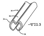
- FIGs. 2 and 3 illustrate an introducer sheath 30 having a proximal region 32, a distal region 34 including a distal port 36 leading to a lumen extending the entire length of the introducer, and a longitudinal region of preferential folding 38.
- the lumen within introducer 30 is clearly visible in FIG. 3 .
- the introducer 30 is constrained in a first configuration having a relatively small transverse profile. This is accomplished by providing the introducer 30 with two longitudinal regions of preferential folding 38, preferably diametrically opposed to each other. Only the top such region is visible in the drawing.
- Other embodiments have more than two lines of preferential folding 38 to allow for increased inward folding of the introducer sidewall.
- the lines of preferential folding 38 can also be lines of preferential tearing or separation. Such lines of preferential tearing can be a weakened region that is scored part way through the thickness of the introducer sidewall.
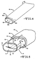
- the introducer 30 typically has a relatively thin sidewall that is not sufficiently strong to withstand being pushed into a vasculatory system, and the like, without collapsing. For that reason, a dilator 40 ( FIG. 2 ) is disposed within the introducer lumen to provide internal stiffening.
- the dilator 40 has a length extending from a tapered distal tip 42 to a proximal region 44.
- the introducer 30 and dilator 40 are preferably cooperatively sized and configured with the introducer distal end or region 34 being releasably secured to the dilator 40 so that the introducer 30 is pulled through tissue or rides along with the dilator to the target site. That way, the tapered distal tip 42 facilitates moving the dilator 40 through the introducer 30 and for moving the introducer/dilator assembly through tissue or a vasculature.
- the introducer 30 and dilator 40 have an outer diameter sized sufficiently small to fit through a 12-gauge needle lumen. This is partially the result of the preferential folding regions 38 providing outwardly facing peaks 48 and inwardly facing valleys 50.
- the peaks 48 and valleys 50 extend along the majority of the length of the introducer 30 and dilator 40 and provide the assembly with a relatively low profile in cross-section.
- Other embodiments are sized to fit through a 14-gauge needle.
- a needle from 10- to 20-gauge may be used in various embodiments of the present dilator and introducer assembly.
- the dilator 40 may be useful to provide the dilator 40 with one or more distal mapping electrodes. That would be so that a user could determine that they are near or adjacent to an optimal stimulation location prior to deployment of the lead 10.
- One such electrode is shown at 46.
- a second dilator is advanced through the introducer 30 before a satisfactorily sized lumen is obtained.
- the introducer is self expanding and does not require a second dilator to achieve a satisfactory configuration.
- the introducer material is sufficiently resilient and biased to open up when unconstrained.
- the introducer walls may also be formed of or include shape memory materials to urge the introducer to open when unconstrained.
- the introducer lumen is only partially opened when it is initially positioned in the body. However, the introducer material is pliable enough to permit an oversized lead to be advanced therethrough with the cross-sectional area of the lumen expanding as the lead passes.
- FIG. 4 illustrates the introducer 30 shown in FIGs. 2 and 3 , but in an expanded configuration.
- the expanded form of the introducer will be identified with numerical designation 60 while the collapsed or un-expanded form of the introducer will be identified with numerical designation 30.
- the expanded introducer 60 has a proximal region 62 and a distal region 64 including a distal port 66 leading to a lumen extending the entire length of the introducer.
- the expanded introducer 60 has a relatively larger and wider oval-shaped profile in cross-section than when in its collapsed form shown in FIGs. 2 and 3 .
- Distal electrodes 68A, 68B and 68C provide conductive outer regions useful for mapping.
- the introducer electrodes 68A, 68B and 68C are connected via electrical conductors (not shown) extending along the sidewall to connectors in the introducer proximal region 62.
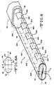
- FIG. 5 illustrates the distal region 64 of the expanded introducer 60 with a neurological lead 70 according to the present invention being advanced from the distal port 66 thereof.
- the lead 70 comprises a sidewall 72 extending from a distal region 74 to a proximal end (not shown).
- the sidewall 72 provides the lead 70 with spaced apart upper and lower sides 76 and 78 extending to and meeting with right and left sides 80 and 82.
- the cross-sectional view shown in FIG. 6A illustrates that the upper and lower sides 76, 78 are generally planer while the right and left sides 80, 82 are radiused. Delineation between the upper side 76 and the right side 80 is indicated by the dashed line 84 as is delineation between the right side 80 and the lower side 78. Delineation between the lower side 78 and the left side 82 is indicated by the dashed line 86 as is delineation between the left side 82 and the upper side 76.
- the lead 70 has a tripole electrode configuration comprising at least one bottom electrode or contact 88A (shown in phantom) supported on or by the lower side 78 and serving as a cathode centered between at least one electrode or contact 90A supported on or by the right side 80 and at least one electrode or contact 92A (shown in phantom) supported on or by the left side 82.
- the right and left contacts 90A, 92A serve as anodes.
- the terms left side and right side are used interchangeably, as it is expected that in most embodiments the two sides will be identical to each other and symmetric, although in some embodiments that may not be the case.
- FIG. 6 also shows that the electrodes 88A to 88E, 90A to 90E and 92A to 92E have a generally rectangular shape. However, that is not necessary.
- the electrode can be radiused in the form of circular contacts, or have both linear and radius portions in the shape of ovals. If fact, the electrode can have a myriad of different shapes only limited by the particular application for which the lead is designed.
- While at least one center electrode 88A flanked by right and left electrodes 90A, 92A is the minimum number contemplated for a tri-pole electrical lead according to the present invention, most lead embodiments will have multiples of this electrode configuration.
- An example is shown in FIG. 6 where the lead 70 has five center electrodes 88A, 88B, 88C, 88D and 88E flanked on the right by electrodes 90A, 90B, 90C, 90D and 90E and on the left by electrodes 92A, 92B, 92C, 92D and 92E.
- a different number of combinations of center, right and left electrodes or contacts are possible.
- Some leads have two, three, four, five, six, seven, eight, or even more tri-pole electrode combinations. In any event, it is preferred that the respective electrodes do not extend past the lines 84, 86 delineating the bottom side 78 from the right and left sides 80, 92.
- FIG. 6A also shows that the lead 70 is symmetric in cross-section along an x-axis indicated by the dashed line 94 and along a y-axis indicated by the dashed line 96.
- the x- and y-axes 94, 96 bisect the lead body 70.
- the bottom electrodes 88A to 88E are generally centered on the y-axis 94 while the right electrodes 90A to 90E and the left electrodes 92A to 92E are generally centered on the y-axis 96.
- the center, right and left electrodes are not centered, but the majority of their exposed surface areas reside on the bottom, right or left sides, as the case may be.
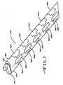
- the right and left side electrodes 90A to 90E and 92A to 92E extend slightly under the lead body onto the lower side 78.
- An example of this is shown in FIG. 7 at the distal region 74A of lead 70A where electrodes 90A', 90B', 90C', 90D' and 90E' reside on the right side 80A of the lead and electrodes 92A', 92B', 92C', 92D' and 92E' reside on the left side 78A of the lead, but have a portion of their surface areas extending onto the lower side 78A opposite the upper side 76A.
- the side electrodes 90A' to 90E', 92A' to 92E' may extend around to the upper side 76A of the lead body 70.
- a lead according to the present invention could have 16 channels.
- providing the electrodes in groups that are divisibility by three is not necessary.
- the spacing of the outer right and left electrode arrays could be staggered with respect to the center columnar electrode array.
- Other exemplary embodiments could include splitting a total of 24 electrodes into three columns of eight or have a configuration of ten center electrodes flanked by seven on either side.
- the lead 70 has a body formed of a polymeric material well known to those skilled in the art.
- the electrodes 88A to 88E, 90A to 90E and 92A to 92E are formed of suitably conductive materials, for example platinum, iridium, palladium, and combinations and alloys thereof. Some leads have each electrode individually addressable, while others have the respective side electrodes 90A to 90E, 92A to 92E electrically connected to each other.
- a 14-gauge needle or a range of sizes from 10 to 20-gauge, is used to access the epidural space using access methods similar to those currently in use.
- the collapsed introducer 30 and corresponding dilator 40 are passed through the needle into the epidural space and positioned near the stimulation target.
- the "collapsed" dilator is then removed, allowing the introducer to assume its expanded form. It may be necessary to manually expand the introducer with an expanding dilator. Alternatively, just passing the lead 70 may expand the introducer.
- the lead 70 is then moved through and out of the expanded introducer 60 so that the at least one central cathode electrode 88A faces towards the spinal cord flanked on either side by the at least one right and left electrodes 90A and 92A.
- the electrode may be stylet driven and positioned much like current percutaneous electrodes.
- Some features of the electrode design include a directional set of one or more cathodes.
- the cathodes can be facing the spinal cord, limiting the amount of current flowing into "non-target" tissue. This improves electrical efficiency and limits potential adverse effects of stimulating tissue such as muscle, etc.
- the edge or side contacts 90A, 92A are not directional and typically act as the anode, or electrical return path. As such, stimulation is not anticipated at the anodes. In other embodiments, the side contacts 90A, 92A act as cathode and the center electrode 88A is the return anode. In any event, close contact spacing between the cathodes and anodes is desirable for many embodiments. That way, the electrical field can be "steered” to the stimulation target by careful design of the spacing and electrical properties of the at least one cathode and the at least one anode.
- the lead 70 has an aspect ratio that is wider along the y-axis than it is high along the x-axis in many embodiments.
- the width is a factor of from about 1.5 times to about 10x the height, preferably from about 3x to about 5x the height of the lead 70. This helps stabilize the lead 70 and electrodes into the appropriate orientation by making it difficult to "flip" the lead once it is positioned.
- the lead body along much of its length is essentially the same dimensionally as the lead distal region 74 carrying the electrodes. This limits the opportunity for tissue in-growth around the lead 70, thereby allowing for easier lead repositioning or removal.
- the proximal region of the lead 70 is split into multiple sets of connector contacts for compatibility with a pulse generator.
- Some embodiments of the lead 70 have a steerable distal tip, for example, controllably deflectable from the introducer's 30/60 proximal region.
- Some introducers 30/60 have one or more electrode contacts at the introducer distal tip.
- Some introducers may be slittable or splittable, to allow for removing the introducer from over the lead 70 without having to slide the introducer over the lead's proximal end.
- Such introducers may have a region of preferential weakness, such as a scored or perforated region.
- a proximal slitter may be used in some embodiments to slit the introducer as it is being removed from the lead.
- the dilator has one or more distal region electrodes which may be used for mapping or other purposes, both prior to and after the lead 70 has been positioned.
- the method may include aligning the at least one first, second and third electrodes with each other along a transverse axis, perpendicular to a longitudinal axis of the lead body.
- the method may include grouping the plurality of first, second and third electrodes in groups of three.
- the method may include providing the plurality of first, second and third electrodes being individually, electrically addressable through conductors extending to the lead body proximal region.
- the method may include providing the second, right side electrodes and the third, left side electrodes extending to the upper side of the lead.
- the method may include providing the second, right side electrodes and the third, left side electrodes extending to the lower side of the lead.
- the method may include providing the lead body distal region having an aspect ratio of width to height of from about 1.5 to 10.
- the method may include centering the at least one first, second and third electrodes along the respective lower, right and left sides of the lead body.
- the method may include providing the at least one first electrode as a cathode and the at least one second and third electrodes as return anodes.
- the method may include providing the at least one first electrode as an anode and the at least one second and third electrodes as cathodes.
- the method may include providing more center electrodes than right and left electrodes.
- the method may include providing fewer center electrodes than right and left electrodes.
- the method may include any combination of the aforementioned features.
Landscapes
- Health & Medical Sciences (AREA)
- Neurology (AREA)
- Neurosurgery (AREA)
- Orthopedic Medicine & Surgery (AREA)
- Cardiology (AREA)
- Heart & Thoracic Surgery (AREA)
- Engineering & Computer Science (AREA)
- Biomedical Technology (AREA)
- Nuclear Medicine, Radiotherapy & Molecular Imaging (AREA)
- Radiology & Medical Imaging (AREA)
- Life Sciences & Earth Sciences (AREA)
- Animal Behavior & Ethology (AREA)
- General Health & Medical Sciences (AREA)
- Public Health (AREA)
- Veterinary Medicine (AREA)
- Electrotherapy Devices (AREA)
Claims (11)
- Implantierbarer medizinischer elektrischer Anschluss (10, 70), wobei der Anschluss (10, 70) Folgendes aufweist:a) einen länglichen Körper (12) mit einer Länge, die sich von einer nahen Region (18) zu einer entfernten Region (14, 74) erstreckt, wobei die entfernte Region (14, 74) des Anschlusskörpers (12) im Querschnitt quer zu ihrer Länge eine ebene Oberseite (76), eine ebene Unterseite (78), eine teilkreisförmige rechte Seite (80) und eine teilkreisförmige linke Seite (82) aufweist, wobei die teilkreisförmigen rechten und linken Seiten (80, 82) auf die ebenen oberen und unteren Seiten (76, 78) treffen, um der entfernten Region (14, 74) des Anschlusses im Querschnitt eine ovale Form zu verschaffen, und wobei die entfernte Region (14, 74) des Anschlusskörpers ein Aspektverhältnis der Breite zur Höhe zwischen ungefähr 1,5 und ungefähr 10 aufweist;b) mindestens eine erste, mittlere Elektrode (88A), die an der entfernten Region (14, 74) des Anschlusskörpers (12) durch die Unterseite (78) getragen wird;c) mindestens eine zweite, rechte Elektrode (90A), die an der entfernten Region (14, 74) des Anschlusskörpers (12) durch die rechte Seite (80) getragen wird; undd) mindestens eine dritte, linke Elektrode (92A), die an der entfernten Region (14, 74) des Anschlusskörpers (12) durch die linke Seite (82) getragen wird.
- Anschluss nach Anspruch 1, wobei die jeweils mindestens einmal vorhandenen ersten, zweiten und dritten Elektroden (88A, 90A, 92A) zueinander entlang einer Querachse senkrecht zu einer Längsachse des Anschlusskörpers (12) ausgerichtet sind.
- Anschluss nach Anspruch 1 oder 2, wobei die Vielzahl von ersten, zweiten und dritten Elektroden (88A-88E, 90A-90E, 92A-92E) in Gruppen von je dreien vorliegt.
- Anschluss nach Anspruch 1, 2 oder 3, wobei es mehr Mittelelektroden als rechte und linke Elektroden gibt.
- Anschluss nach Anspruch 1, 2, 3 oder 4, wobei es weniger Mittelelektroden als rechte und linke Elektroden gibt.
- Anschluss nach einem der vorhergehenden Ansprüche, wobei die Vielzahl von ersten, zweiten und dritten Elektroden (88A-88E, 90A-90E, 92A-92E) individuell elektrisch durch Leiter adressierbar ist, die sich hin zu der nahen Region (18) des Anschlusskörpers erstrecken.
- Anschluss nach einem der vorhergehenden Ansprüche, wobei sich die zweiten, rechten Seitenelektroden (90A'-90E') und die dritten, linken Seitenelektroden (92A'-92E') zu der Oberseite (76A) des Anschlusses erstrecken.
- Anschluss nach einem der vorhergehenden Ansprüche, wobei sich die zweiten, rechten Seitenelektroden (90A'-90E') und die dritten, linken Seitenelektroden (92A'-92E') zu der Unterseite (78A) des Anschlusses erstrecken.
- Anschluss nach einem der vorhergehenden Ansprüche, wobei die mindestens eine erste, zweite oder dritte Elektrode (88A, 90A) entlang der jeweiligen unteren, rechten oder linke Seite (78, 80, 82) des Anschlusskörpers (12) zentriert ist.
- Anschluss nach einem der vorhergehenden Ansprüche, wobei die mindestens eine erste Elektrode (88A) eine Kathode ist und die jeweils mindestens einmal vorhandene zweite und dritte Elektrode (90A, 92A) Echoanoden sind.
- Anschluss nach einem der vorhergehenden Ansprüche, wobei die mindestens eine erste Elektrode (88A) eine Anode ist und die jeweils mindestens einmal vorhandenen zweiten und dritten Elektroden (90A, 92A) Kathoden sind.
Applications Claiming Priority (1)
| Application Number | Priority Date | Filing Date | Title |
|---|---|---|---|
| US94670107P | 2007-06-27 | 2007-06-27 |
Publications (2)
| Publication Number | Publication Date |
|---|---|
| EP2008686A1 EP2008686A1 (de) | 2008-12-31 |
| EP2008686B1 true EP2008686B1 (de) | 2011-08-17 |
Family
ID=39869673
Family Applications (1)
| Application Number | Title | Priority Date | Filing Date |
|---|---|---|---|
| EP08104581A Active EP2008686B1 (de) | 2007-06-27 | 2008-06-27 | Perkutane Elektrodenanordnung und System |
Country Status (2)
| Country | Link |
|---|---|
| US (1) | US8090450B2 (de) |
| EP (1) | EP2008686B1 (de) |
Families Citing this family (23)
| Publication number | Priority date | Publication date | Assignee | Title |
|---|---|---|---|---|
| WO2010014686A1 (en) | 2008-07-30 | 2010-02-04 | Aleva Neurotherapeutics, S.A. | Apparatus and method for optimized stimulation of a neurological target |
| US8788064B2 (en) | 2008-11-12 | 2014-07-22 | Ecole Polytechnique Federale De Lausanne | Microfabricated neurostimulation device |
| US8670837B2 (en) * | 2010-03-24 | 2014-03-11 | Khosrow Daneshvar | Method and means to adjust the positioning of stimulating neural and muscular electrode |
| WO2011103530A2 (en) | 2010-02-22 | 2011-08-25 | North Richard B | Percutaneous electrode |
| WO2011121089A1 (en) | 2010-04-01 | 2011-10-06 | Ecole Polytechnique Federale De Lausanne (Epfl) | Device for interacting with neurological tissue and methods of making and using the same |
| US8543223B2 (en) | 2011-03-11 | 2013-09-24 | Greatbach Ltd. | Implantable lead with braided conductors |
| EP2879756A1 (de) * | 2012-08-03 | 2015-06-10 | Boston Scientific Neuromodulation Corporation | Systeme und verfahren zur herstellung und verwendung einer multielektrodeneinführvorrichtung für elektrische stimulationssysteme |
| WO2014158723A1 (en) | 2013-03-13 | 2014-10-02 | Boston Scientific Neuromodulation Corporation | System and method for making and using a lead introducer for an implantable electrical stimulation system |
| AU2014228794B2 (en) | 2013-03-15 | 2019-04-18 | The Regents Of The University Of California | Multi-site transcutaneous electrical stimulation of the spinal cord for facilitation of locomotion |
| AU2014315386A1 (en) | 2013-09-06 | 2016-03-03 | Boston Scientific Neuromodulation Corporation | Lead introducer for an implantable electrical stimulation system |
| JP6165990B2 (ja) | 2013-09-06 | 2017-07-19 | ボストン サイエンティフィック ニューロモデュレイション コーポレイション | 埋込み可能な電気刺激システムのためのリード導入器 |
| US9604050B2 (en) | 2014-02-20 | 2017-03-28 | Boston Scientific Neuromodulation Corporation | Systems and methods for percutaneously implanting into a patient a paddle lead of an electrical stimulation system |
| EP3476430B1 (de) | 2014-05-16 | 2020-07-01 | Aleva Neurotherapeutics SA | Vorrichtung zur interaktion mit neurologischem gewebe |
| US11311718B2 (en) | 2014-05-16 | 2022-04-26 | Aleva Neurotherapeutics Sa | Device for interacting with neurological tissue and methods of making and using the same |
| CA2959378A1 (en) | 2014-08-27 | 2016-03-03 | The Regents Of The University Of California | Multi-electrode array for spinal cord epidural stimulation |
| US9474894B2 (en) | 2014-08-27 | 2016-10-25 | Aleva Neurotherapeutics | Deep brain stimulation lead |
| WO2016130575A1 (en) | 2015-02-13 | 2016-08-18 | Boston Scientific Neuromodulation Corporation | Retractor and tools for implantation of electrical stimulation leads |
| US10226616B2 (en) | 2015-04-28 | 2019-03-12 | Boston Scientific Neuromodulation Corporation | Systems and methods for making and using a lead introducer with a seal for an electrical stimulation system |
| WO2017134587A1 (en) | 2016-02-02 | 2017-08-10 | Aleva Neurotherapeutics, Sa | Treatment of autoimmune diseases with deep brain stimulation |
| US12357828B2 (en) | 2017-12-05 | 2025-07-15 | Ecole Polytechnique Federale De Lausanne (Epfl) | System for planning and/or providing neuromodulation |
| US10702692B2 (en) | 2018-03-02 | 2020-07-07 | Aleva Neurotherapeutics | Neurostimulation device |
| CN113453749B (zh) * | 2019-02-19 | 2024-09-20 | 波士顿科学神经调制公司 | 引线引入器以及包括该引线引入器的系统和方法 |
| EP3827875B1 (de) | 2019-11-27 | 2023-07-05 | ONWARD Medical N.V. | Neuromodulationssystem |
Family Cites Families (37)
| Publication number | Priority date | Publication date | Assignee | Title |
|---|---|---|---|---|
| US4630611A (en) * | 1981-02-02 | 1986-12-23 | Medtronic, Inc. | Orthogonally-sensing lead |
| JPH0758623A (ja) * | 1993-08-20 | 1995-03-03 | Mitsubishi Electric Corp | Cmos入力回路 |
| US5417719A (en) * | 1993-08-25 | 1995-05-23 | Medtronic, Inc. | Method of using a spinal cord stimulation lead |
| US5501703A (en) | 1994-01-24 | 1996-03-26 | Medtronic, Inc. | Multichannel apparatus for epidural spinal cord stimulator |
| US5462545A (en) * | 1994-01-31 | 1995-10-31 | New England Medical Center Hospitals, Inc. | Catheter electrodes |
| US5713867A (en) * | 1996-04-29 | 1998-02-03 | Medtronic, Inc. | Introducer system having kink resistant splittable sheath |
| DE19758114C2 (de) | 1997-12-17 | 2001-08-23 | Biotronik Mess & Therapieg | Elektrodenanordnung zur Rückenmarkstimulation |
| WO1999056818A1 (en) * | 1998-04-30 | 1999-11-11 | Medtronic, Inc. | Multiple electrode lead body for spinal cord stimulation |
| US6161047A (en) * | 1998-04-30 | 2000-12-12 | Medtronic Inc. | Apparatus and method for expanding a stimulation lead body in situ |
| US6064905A (en) * | 1998-06-18 | 2000-05-16 | Cordis Webster, Inc. | Multi-element tip electrode mapping catheter |
| US6309401B1 (en) * | 1999-04-30 | 2001-10-30 | Vladimir Redko | Apparatus and method for percutaneous implant of a paddle style lead |
| US7200446B2 (en) * | 1999-07-21 | 2007-04-03 | Borkan William N | Catheter leads for the intrathecal space and method of use |
| US6587733B1 (en) * | 2000-02-08 | 2003-07-01 | Medtronic, Inc. | Percutaneous surgical lead body with directed stimulation |
| US6895283B2 (en) * | 2000-08-10 | 2005-05-17 | Advanced Neuromodulation Systems, Inc. | Stimulation/sensing lead adapted for percutaneous insertion |
| US6510347B2 (en) * | 2000-08-17 | 2003-01-21 | William N. Borkan | Spinal cord stimulation leads |
| US6745079B2 (en) * | 2001-11-07 | 2004-06-01 | Medtronic, Inc. | Electrical tissue stimulation apparatus and method |
| US7047084B2 (en) * | 2002-11-20 | 2006-05-16 | Advanced Neuromodulation Systems, Inc. | Apparatus for directionally stimulating nerve tissue |
| WO2005053789A2 (en) * | 2003-11-25 | 2005-06-16 | Advanced Neuromodulation Systems, Inc. | Directional stimulation lead and orientation system, and improved percutaneous-insertion needle and method of implanting a lead |
| US20050203600A1 (en) * | 2004-03-12 | 2005-09-15 | Scimed Life Systems, Inc. | Collapsible/expandable tubular electrode leads |
| US20050256541A1 (en) * | 2004-04-30 | 2005-11-17 | Medtronic, Inc. | Catheter with temporary stimulation electrode |
| US20050283216A1 (en) * | 2004-06-21 | 2005-12-22 | Pyles Stephen T | Apparatus and method for displacing tissue obstructions |
| US20060206182A1 (en) * | 2004-06-21 | 2006-09-14 | Pyles Stephen T | Apparatus and method for displacing tissue obstructions |
| US9050455B2 (en) * | 2004-10-21 | 2015-06-09 | Medtronic, Inc. | Transverse tripole neurostimulation methods, kits and systems |
| US9079018B2 (en) * | 2004-10-21 | 2015-07-14 | Medtronic, Inc. | Implantable medical electrical leads, kits, systems and methods of use thereof |
| US9026228B2 (en) * | 2004-10-21 | 2015-05-05 | Medtronic, Inc. | Transverse tripole neurostimulation lead, system and method |
| US7945331B2 (en) * | 2005-01-11 | 2011-05-17 | Bradley D. Vilims | Combination electrical stimulating and infusion medical device and method |
| US7146224B2 (en) * | 2005-01-19 | 2006-12-05 | Medtronic, Inc. | Apparatus for multiple site stimulation |
| US7702385B2 (en) * | 2005-11-16 | 2010-04-20 | Boston Scientific Neuromodulation Corporation | Electrode contact configurations for an implantable stimulator |
| US20060271137A1 (en) * | 2005-05-25 | 2006-11-30 | The Cleveland Clinic Foundation | Apparatus and system to stimulate a nerve |
| US7769472B2 (en) * | 2005-07-29 | 2010-08-03 | Medtronic, Inc. | Electrical stimulation lead with conformable array of electrodes |
| US7822482B2 (en) * | 2005-07-29 | 2010-10-26 | Medtronic, Inc. | Electrical stimulation lead with rounded array of electrodes |
| US20070118198A1 (en) * | 2005-11-07 | 2007-05-24 | Prager Joshua P | Neurostimulation lead with concentric electrodes |
| US7672734B2 (en) | 2005-12-27 | 2010-03-02 | Boston Scientific Neuromodulation Corporation | Non-linear electrode array |
| US7729781B2 (en) * | 2006-03-16 | 2010-06-01 | Greatbatch Ltd. | High efficiency neurostimulation lead |
| US7617006B2 (en) * | 2006-04-28 | 2009-11-10 | Medtronic, Inc. | Medical electrical lead for spinal cord stimulation |
| US7515968B2 (en) * | 2006-04-28 | 2009-04-07 | Medtronic, Inc. | Assembly method for spinal cord stimulation lead |
| US8666506B2 (en) * | 2006-06-30 | 2014-03-04 | Medtronic, Inc. | Selecting electrode combinations for stimulation therapy |
-
2008
- 2008-06-26 US US12/146,961 patent/US8090450B2/en active Active
- 2008-06-27 EP EP08104581A patent/EP2008686B1/de active Active
Also Published As
| Publication number | Publication date |
|---|---|
| US8090450B2 (en) | 2012-01-03 |
| US20090005844A1 (en) | 2009-01-01 |
| EP2008686A1 (de) | 2008-12-31 |
Similar Documents
| Publication | Publication Date | Title |
|---|---|---|
| EP2008686B1 (de) | Perkutane Elektrodenanordnung und System | |
| EP1818074B1 (de) | Selbstfaltende paddelförmige Leitung und Verfahren zur Herstellung einer paddelförmigen Leitung | |
| US9522269B2 (en) | Needle and lead and methods of use | |
| EP2252365B1 (de) | Temporäre identifizierungsvorrichtung für neurostimulationsleiter | |
| US8805543B2 (en) | Insertion tool for paddle-style electrode | |
| JP4680253B2 (ja) | 折りたたみ可能/拡張可能な筒状電極リード | |
| US11045221B2 (en) | Steerable percutaneous paddle stimulation lead | |
| US9283375B2 (en) | Leads with segmented electrodes for electrical stimulation of planar regions and methods of making and using | |
| US9026228B2 (en) | Transverse tripole neurostimulation lead, system and method | |
| EP2854669B1 (de) | Perkutaner implantationskit für eine leitung zur elektrischen stimulierung zur stimulierung der hinterwurzelganglion | |
| ES2506441T3 (es) | Sistemas y métodos para fabricar y usar electrodos segmentados alineados radialmente para cables de sistemas de estimulación eléctrica | |
| EP2675520B1 (de) | Systeme und verfahren zur implantation von paddelelektrodenanordnungen elektrischer stimulationssysteme | |
| US9050455B2 (en) | Transverse tripole neurostimulation methods, kits and systems | |
| US8805544B2 (en) | Insertion tool for paddle-style electrode | |
| US8801728B2 (en) | Introduction of medical lead into patient | |
| US20160213916A1 (en) | Self-expanding neurostimulation leads having broad multi-electrode arrays | |
| US20030109913A1 (en) | Bio-implant and method of making the same | |
| US20180021569A1 (en) | Systems and methods for making and using an electrical stimulation system for stimulation of dorsal root ganglia | |
| CA2636733C (en) | Percutaneous electrode array and system | |
| US20150142010A1 (en) | Neurostimulation leads having two-dimensional arrays | |
| US10576269B2 (en) | Force-decoupled and strain relieving lead and methods of making and using |
Legal Events
| Date | Code | Title | Description |
|---|---|---|---|
| PUAI | Public reference made under article 153(3) epc to a published international application that has entered the european phase |
Free format text: ORIGINAL CODE: 0009012 |
|
| AK | Designated contracting states |
Kind code of ref document: A1 Designated state(s): AT BE BG CH CY CZ DE DK EE ES FI FR GB GR HR HU IE IS IT LI LT LU LV MC MT NL NO PL PT RO SE SI SK TR |
|
| AX | Request for extension of the european patent |
Extension state: AL BA MK RS |
|
| RAP1 | Party data changed (applicant data changed or rights of an application transferred) |
Owner name: GREATBATCH LTD. |
|
| 17P | Request for examination filed |
Effective date: 20090618 |
|
| 17Q | First examination report despatched |
Effective date: 20090715 |
|
| AKX | Designation fees paid |
Designated state(s): DE FR IT |
|
| GRAP | Despatch of communication of intention to grant a patent |
Free format text: ORIGINAL CODE: EPIDOSNIGR1 |
|
| GRAS | Grant fee paid |
Free format text: ORIGINAL CODE: EPIDOSNIGR3 |
|
| GRAA | (expected) grant |
Free format text: ORIGINAL CODE: 0009210 |
|
| AK | Designated contracting states |
Kind code of ref document: B1 Designated state(s): DE FR IT |
|
| REG | Reference to a national code |
Ref country code: DE Ref legal event code: R096 Ref document number: 602008008872 Country of ref document: DE Effective date: 20111020 |
|
| PG25 | Lapsed in a contracting state [announced via postgrant information from national office to epo] |
Ref country code: IT Free format text: LAPSE BECAUSE OF FAILURE TO SUBMIT A TRANSLATION OF THE DESCRIPTION OR TO PAY THE FEE WITHIN THE PRESCRIBED TIME-LIMIT Effective date: 20110817 |
|
| PLBE | No opposition filed within time limit |
Free format text: ORIGINAL CODE: 0009261 |
|
| STAA | Information on the status of an ep patent application or granted ep patent |
Free format text: STATUS: NO OPPOSITION FILED WITHIN TIME LIMIT |
|
| 26N | No opposition filed |
Effective date: 20120521 |
|
| REG | Reference to a national code |
Ref country code: DE Ref legal event code: R097 Ref document number: 602008008872 Country of ref document: DE Effective date: 20120521 |
|
| REG | Reference to a national code |
Ref country code: FR Ref legal event code: PLFP Year of fee payment: 8 |
|
| REG | Reference to a national code |
Ref country code: DE Ref legal event code: R082 Ref document number: 602008008872 Country of ref document: DE Representative=s name: WINTER, BRANDL - PARTNERSCHAFT MBB, PATENTANWA, DE Ref country code: DE Ref legal event code: R082 Ref document number: 602008008872 Country of ref document: DE Representative=s name: WINTER, BRANDL, FUERNISS, HUEBNER, ROESS, KAIS, DE Ref country code: DE Ref legal event code: R081 Ref document number: 602008008872 Country of ref document: DE Owner name: QIG GROUP, LLC, CLARENCE, US Free format text: FORMER OWNER: GREATBATCH, LTD., CLARENCE, N.Y., US |
|
| REG | Reference to a national code |
Ref country code: FR Ref legal event code: TP Owner name: QIG GROUP, LLC, US Effective date: 20160502 |
|
| REG | Reference to a national code |
Ref country code: FR Ref legal event code: PLFP Year of fee payment: 9 |
|
| REG | Reference to a national code |
Ref country code: FR Ref legal event code: PLFP Year of fee payment: 10 |
|
| REG | Reference to a national code |
Ref country code: FR Ref legal event code: PLFP Year of fee payment: 11 |
|
| PGFP | Annual fee paid to national office [announced via postgrant information from national office to epo] |
Ref country code: DE Payment date: 20250627 Year of fee payment: 18 |
|
| PGFP | Annual fee paid to national office [announced via postgrant information from national office to epo] |
Ref country code: FR Payment date: 20250625 Year of fee payment: 18 |