EP2007683B1 - Wasserfilter-kartuschensystem mit kombinierter verschneideventiltechnik und einstellvorrichtung in der kerze und im kopf - Google Patents
Wasserfilter-kartuschensystem mit kombinierter verschneideventiltechnik und einstellvorrichtung in der kerze und im kopf Download PDFInfo
- Publication number
- EP2007683B1 EP2007683B1 EP07724044.8A EP07724044A EP2007683B1 EP 2007683 B1 EP2007683 B1 EP 2007683B1 EP 07724044 A EP07724044 A EP 07724044A EP 2007683 B1 EP2007683 B1 EP 2007683B1
- Authority
- EP
- European Patent Office
- Prior art keywords
- filter
- raw water
- water distribution
- filter according
- head
- Prior art date
- Legal status (The legal status is an assumption and is not a legal conclusion. Google has not performed a legal analysis and makes no representation as to the accuracy of the status listed.)
- Active
Links
Images

Classifications
-
- B—PERFORMING OPERATIONS; TRANSPORTING
- B01—PHYSICAL OR CHEMICAL PROCESSES OR APPARATUS IN GENERAL
- B01D—SEPARATION
- B01D35/00—Filtering devices having features not specifically covered by groups B01D24/00 - B01D33/00, or for applications not specifically covered by groups B01D24/00 - B01D33/00; Auxiliary devices for filtration; Filter housing constructions
- B01D35/14—Safety devices specially adapted for filtration; Devices for indicating clogging
- B01D35/153—Anti-leakage or anti-return valves
-
- C—CHEMISTRY; METALLURGY
- C02—TREATMENT OF WATER, WASTE WATER, SEWAGE, OR SLUDGE
- C02F—TREATMENT OF WATER, WASTE WATER, SEWAGE, OR SLUDGE
- C02F1/00—Treatment of water, waste water, or sewage
- C02F1/001—Processes for the treatment of water whereby the filtration technique is of importance
- C02F1/004—Processes for the treatment of water whereby the filtration technique is of importance using large scale industrial sized filters
-
- B—PERFORMING OPERATIONS; TRANSPORTING
- B01—PHYSICAL OR CHEMICAL PROCESSES OR APPARATUS IN GENERAL
- B01D—SEPARATION
- B01D2201/00—Details relating to filtering apparatus
- B01D2201/30—Filter housing constructions
- B01D2201/301—Details of removable closures, lids, caps, filter heads
- B01D2201/302—Details of removable closures, lids, caps, filter heads having inlet or outlet ports
-
- B—PERFORMING OPERATIONS; TRANSPORTING
- B01—PHYSICAL OR CHEMICAL PROCESSES OR APPARATUS IN GENERAL
- B01D—SEPARATION
- B01D2201/00—Details relating to filtering apparatus
- B01D2201/40—Special measures for connecting different parts of the filter
- B01D2201/4023—Means for connecting filter housings to supports
-
- B—PERFORMING OPERATIONS; TRANSPORTING
- B01—PHYSICAL OR CHEMICAL PROCESSES OR APPARATUS IN GENERAL
- B01D—SEPARATION
- B01D2201/00—Details relating to filtering apparatus
- B01D2201/40—Special measures for connecting different parts of the filter
- B01D2201/4046—Means for avoiding false mounting of different parts
-
- C—CHEMISTRY; METALLURGY
- C02—TREATMENT OF WATER, WASTE WATER, SEWAGE, OR SLUDGE
- C02F—TREATMENT OF WATER, WASTE WATER, SEWAGE, OR SLUDGE
- C02F2201/00—Apparatus for treatment of water, waste water or sewage
- C02F2201/002—Construction details of the apparatus
- C02F2201/006—Cartridges
-
- C—CHEMISTRY; METALLURGY
- C02—TREATMENT OF WATER, WASTE WATER, SEWAGE, OR SLUDGE
- C02F—TREATMENT OF WATER, WASTE WATER, SEWAGE, OR SLUDGE
- C02F2301/00—General aspects of water treatment
- C02F2301/04—Flow arrangements
- C02F2301/043—Treatment of partial or bypass streams
Definitions
- the present invention relates to a water filter according to the preamble of claim 1.
- Softening / decarbonating / demineralizing systems based on replacement filter cartridges include a trimming device for adjusting a pre-determined water quality for the purpose of a co-ordinated mixture of filtered water with unfiltered or other water treatment medium Water.
- These systems are used in drinking water treatment in private households and in the catering trade, as a central or decentralized installation for the supply of tapping points and in particular for the supply of modern kitchen appliances, eg coffee machines, water taps and ice makers (eg in modern refrigerators) and, moreover, in the commercial sector, for supplying vending machines for the preparation of cold drinks and hot drinks, of dishwashers and steamers for the purpose of flavor optimization of the processed or prepared beverages and food and to protect the machines from water-related technical problems.
- Verschneideventils in the cartridge dar.
- constructions which allow filtration of the blended water and those which do not allow filtration of the blended water.
- a concept without filtration of the blended water is eg in the US 6923910 B2 described.
- the head structures are simple, since they do not contain a blending valve and only 2 volume flows must be performed.
- the present invention has for its object to improve a water filter according to the introductory nature.
- the present invention relates a water filter, consisting of a filter head, a replaceable
- Filter cartridge for adjusting a partial flow ratio between at least two flow paths, wherein at least one flow path comprises a filter section.
- the second or yet another flow path may be e.g. a further filter section, a Verschneidesize for mixing the guided over the filter section water with a preferably adjustable proportion of possibly passed through a carbon filter raw water or another water treatment line.
- the water filter is characterized in that the adjusting device comprises a raw water distribution element arranged in or on the filter head and a partial flow channel guide element which is complementary thereto and arranged in or on the filter cartridge.
- this embodiment of a water filter additionally has the advantage that the blend setting between the filter section and bypass section by two complementary, only when installing a filter cartridge in a filter head 1966hegbare and / or against each other positionable Verten-adjustment takes place and thus a desired or unwanted manipulation and a concomitant, possibly improper use of the filter cartridge further impeded or made impossible.
- the raw water distribution element is formed as part of the filter head.
- a sleeve and / or ring with at least one passage or blocking element such as an opening or a cover or a closure to an opening, which can cooperate with a complementary element on the filter cartridge. Due to the arrangement in the filter head, it can be pre-positioned accordingly.
- This may optionally otherwise required alignment of the Verismeinstellelementes in its relative position to the filter head account for a first, basic setting operation of the blend ratio. An adjustment of the relative position of the two mutually complementary elements when using a new filter cartridge is therefore no longer necessary. It results automatically from the old blend setting and the installation-related operating position of the filter cartridge. Nevertheless, an optionally required readjustment of the blend ratio by the operation of a corresponding, acting on the raw water distribution element adjustment is possible.
- a corresponding water filter can in turn be designed as part of a water filter system in which the same head for different applications combined with different raw water distribution elements and consequently with different filter cartridges can. And conversely, with the same adjustment element with different filter cartridges different Kanalstrom arrangementsgeometrien could be realized, that is with the same head, candles with different flow characteristics and vice versa.
- various embodiments in the connection between the raw water distribution element and the filter head are conceivable. For applications in which it is important that tampering can be reliably prevented, it is advisable to use a non-detachable connection between the raw water distribution element and the filter head.
- a detachable connection between the raw water distribution element and the filter head can be considered advantageous.
- a special tool for re-releasing an already installed raw water distribution element can be provided here. Such a tool is particularly advantageous if the raw water distribution element is designed as a removable element.
- a control element which may be e.g. includes an actuator.
- this may for example be a thumbwheel with a corresponding connection to the raw water distribution element.
- an adjustment by means of a motor or with another suitable adjusting means is conceivable, for example if the required water quality no longer corresponds to the desired water quality due to the operating time or other causes and accordingly a readjustment should be required.
- Such a control element can thus basically comprise a control loop, which under certain circumstances also checks the quality or quality of the filtered water and, if necessary, readjusts the setting of the waste section, for example with a corresponding positioning unit, and locks it in a particularly advantageous manner.
- the raw-water distribution element may comprise at least one passage and / or cover element, which may be e.g. dazzling cooperates with their respective associated opening for the filter section or for the bypass section. Accordingly, upon rotation of the raw water distribution element, a change in the active flow cross section of one or the other route, or in a particularly preferred embodiment, a complementary change of the two passage cross sections, so that the total remaining effective Automatelassquerites to maintain a substantially constant internal system pressure equal remains. As a result, it is possible to effect a uniform waste and filter effect that is essentially independent of the flow volume for all filter cartridges installed in a filter head, even for different blend settings.
- the raw water distribution element may take various forms, e.g. a ring or disc shape.
- a disc-shaped or annular embodiment can realize, for example, the above-described aperture effect by covering or releasing the two or optionally also several inlets, filter section or bypass section with two elements aligned flat to each other.
- the raw water distribution element may also have a sleeve shape.
- This can be achieved, for example, by arranging two or more tubes or sleeves oriented coaxially with respect to one another, wherein at least one of the two sleeves has at least one passage opening, but preferably a plurality, passing through the other sleeve during a relative displacement movement of the two sleeves relative to one another is hidden or released or will be.
- This relative displacement movement between the two sleeves can, for example, over a correspondingly provided and, for example actuated by one of the above-described actuating means thread can be carried out.
- other adjustment mechanisms are also conceivable, such as drawing and / or pressure means, preferably in combination with locking means.
- the partial flow channel guide element that is complementary to the raw water distribution element preferably has at least one filter line inlet and at least one waste line inlet or filter or water treatment line inlet.
- the filter-line inlet and / or the waste-line inlet or the filter or water-treatment line inlet can also have a plurality of inlet openings. In this way, for example, an influence on the flow ratio in the filter cartridge is possible, but it may also give reasons for coarse prefiltration cause such a structure, so that in the line washed up larger particles can not penetrate into the filter and possibly clogged.
- the inlet openings may be slit-shaped and / or also predominantly circular to oval.
- the effectively released from the raw water distribution element, formed from the sum of the two partial flows total cross section of the partial flow channel guide element is substantially equal in all blend settings, so that a predominantly constant internal pressure ratio in the system and a from Flow volume largely independent waste ratio is ensured.
- an encryption is formed between an element associated with the filter head and an element associated with the filter cartridge.
- Such encryption preferably has axially extending complementary elements.
- One possible embodiment of such encryption could be e.g. be realized by a gearing.
- This toothing may comprise one or more teeth, which engage in correspondingly complementary recesses and, in a particularly preferred manner, effect an actuation of elements arranged in the head and activatable or deactivatable by a rotational movement.
- Such an actuatable element can be, for example, an inlet valve, an outlet valve and / or an expansion valve, a pipe water distribution element and / or a combination of one or more of these elements.
- Such an encryption element can thus simultaneously also be used as a control element for a placement-dependent positioning of the inlet and / or outlet valve of an expansion valve or the like.
- a corresponding control element could certainly also be designed as a separately designed control element, for example in the form of a Adjusting ring and / or an adjusting sleeve.
- These can in turn comprise a further actuating element, such as an actuating and / or adjusting cam, a guiding and / or adjusting edge or the like.
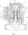
- the system of the water filter 1 consists of a filter head 2, which is permanently installed and connected to the drinking water supply, and a filter cartridge 3, which is interchangeable.
- the replacement of the filter cartridge which is also referred to elsewhere in the description with the same meaning as “filter cartridge”, takes place after exhaustion of the treatment media or after the period of use ( FIG. 1 ).
- the filter head 2 consists essentially of a filter head housing 4, which consists of two concentric holes 5, 6 with different diameters for receiving the filter cartridge 3. Similar head-candle adaptations are already known in the market. This construction has a Veritesinstellhülse 17 with one or more drivers 8, which is arranged rotatably in the filter head 2 from the outside. The proportion of waste can be adjusted continuously or in graduated values by means of rotation of the blend adjustment sleeve 17 on the head 2 (eg 0%, 10%, 20% 30%, 40% etc.) are set latching.
- a thumbwheel 23 is provided, for example, in the form of a cap, which is connected via a corresponding driver with the blend adjustment sleeve 17 a rotational movement transmitting.
- the adjustment resistance of this cap for rotating the associated Verteninstellhülse 17 can be influenced for example via the frictional resistance of the seal 25 relative to the housing 4 and / or other contact surfaces between the Verteninstellhülse 17 and the housing 4.
- an additional detent 24 may be provided, such as here by biasing the outer cap edges relative to the outer side of the housing 4 facing it.
- the detents may be formed for this purpose, for example by a mutually engaging toothing or the like.
- a fixing means of the cap 23 on the blend adjustment sleeve 17 for example, a screw 26 are used. However, snap closures or other suitable connections are also conceivable.
- the blend adjustment sleeve 17 has a correspondingly arranged and formed opening 27 for the passage of the filtrate stream.
- a second opening 28 is provided here opposite in the blend adjustment sleeve 17 for access to a relaxation and / or purge valve 19.
- the filter cartridge 3 has two sealing elements 9, 10, which seal the cartridge to the outside: a seal 10 for separating the Autofiltrats and one for sealing 9 of the raw water inlet.
- a Veritesinstellring 7 is integrated as a so-called raw water distribution element, which divides the raw water in the inlet of the candle 3 and the separate treatment lines for z.B. Softening 12 and waste 13 supplies.
- the inlet 12 for the water to be treated is located approximately 180 ° offset from the inlet 13 for the waste water.
- the exact position of the inlets for the treatment channel and the blended water channel in the candle 3 can be adjusted individually with the Verismeinstellring 7 in order to obtain the desired blend setting and the corresponding flow resistance as a function of the angle of rotation of the Verismeinstellrings 7.
- the rotation of the ring 7 is in a first embodiment, in which the Verismeinstellring 7 is disposed on the filter cartridge 3, during the installation of the filter cartridge 3 in the filter head 2 automatically (forcibly) performed.
- the connection between the filter head and the filter cartridge is produced by, for example, a bayonet 16 with at least two tabs. It can then be carried out a rotational movement of about 90 °. If the bayonet tabs are smaller than the openings, then twist angles greater than 90 ° are possible in principle. However, a twist angle of about 90 ° is preferred in a version with 2 bayonet tabs.
- the rotatable ring 7 must have at least one catch hook, preferably two catch hooks, just like the blend setting sleeve 17. Now, if the cartridge 3 is installed (the bayonet is closed), then meet the driving hooks of blend setting sleeve 17 and rotatable ring 7 from a certain angular position during installation. Now, if the installation or rotational movement continues to the closed position of the bayonet, the rotatable ring is held by the driving hook of the head and the cartridge rotates below the (relative to the head) stationary ring 7 and thus adjusts the blend setting of the filter cartridge. 3
- the ring 7 is in a starting position prior to installation.
- the two extreme positions for setting the ring can be considered for the starting position. These are the positions of the ring which allow a complete closure of the cut or a maximum opening of the cut.
- the blend of the filter candle can be opened more or less relative to the starting position
- the waste depending on the position of the Mitauerhaken the Verismeinstellhülse more or less than the initial position when the filter cartridge is screwed into the head.
- the central idea of this design is the use of the rotational movement in the installation of the filter cartridge 3 in the filter head 2 via the bayonet connection 16 for setting the blend ratio.
- the rotation is used to adjust the crop during installation. You can still use this rotational movement to actuate an inlet valve 18 and / or expansion / purge valve 19. So is such a use of the rotational movement in the installation of the filter candle in the head, for example, from the patent US 6949.189. B2 known.
- a closure valve in the filter head by two nested sleeves is formed with suitably arranged holes and sealing elements, wherein the actuation of the rotary valve is carried by driver on the cartridge.
- This construction can not be combined with the above-mentioned blend setting. It is therefore proposed a novel valve actuation mechanism via cam 20 and valve tappet 21. Constructions of this type are otherwise known only in the field of faucet filter ("faucet mount -Wasserfilter”), in which case the actuation of the valve elements via a separate actuating shaft with control lever.
- the actuating shaft is the symmetry axis of the filter cartridge cover. Accordingly, at least one cam 20 is attached to the cartridge cover according to the drawing (preferably two for reasons of symmetry), which pushes back the valve stem 21 when the bayonet connection is closed, whereby the raw water inlet is released. If the filter cartridge is removed from the filter head, the inlet valve 18 is closed.
- the actuating cam 20 can preferably be arranged above the outer sealing element 9. For opening the raw water valve 18th (Inlet to the cartridge) a rotation angle of 5 to 50 °, preferably 10 ° is sufficient.
- a driver 22 is provided above the second sealing element 10 of the filter cartridge cover, which operates a second valve 19 (eg poppet valve) in the filter head, see drawing.
- This valve 19 is closed when the filter cartridge is removed.
- the second valve 19 is also closed when the filter cartridge is installed in the filter head or the bayonet is completely closed.
- the actuation ie opening of the valve 19 is effected by the driver 22 (for reasons of symmetry preferably two drivers), which is designed as a hook and thereby raises the second valve 19.
- the mounting of the valve takes place in an angular range of the bayonet, where the raw water valve 18 is closed and the filter cartridge is anchored in the approximately half-closed bayonet.
- the second valve 19 with an additional externally operated pulling mechanism. This can be done via a screw design or the like. Thus, this valve 19 can then be manually operated in installation position, whereby this valve can then be additionally used as a purge valve for commissioning the filter cartridge.
- the manual operation mechanism In order to maintain the automatic function as a relief valve, the manual operation mechanism must be provided with sufficient clearance. (When the valve is manually operated, the cartridge's actuating hook must not collide with the valve.) Conversely, the manual operating mechanism in the closed position must not hinder automatic opening via the hook.)
- FIG. 1a shows a plan view of the cartridge 3 of the water filter 1 from the FIG. 1 , Central in the middle is the Filter outlet 29 shown, through which the filtered water flow leaves the cartridge 3. Above and below the two arranged on the front side of the outer wall 35 of the filter outlet 29 driver 22 for actuating the expansion and / or Spülventils 19 can be seen.
- the Verastainstellring 7 surrounds the outer wall 35 and has two segments with multiple openings 32 for access to the filter section and a plurality of openings 33 for access to the blending line or bypass section.
- an adjustment for the blend ratio between 0% and 60% is shown by way of example, depending on the related angle adjustment of the Veritesinstellringes 7 in relative position to the thus positioned filter cartridge 3 and to their inlets 14 for the main stream or Filter flow or 15 for the bypass or waste section.
- a fixation between the drivers 8 and the Verismeinstellring 7 provided, preferably in a locking arrangement, for example by a resilient engagement of the pins in correspondingly provided recesses.
- the two cams 20 are shown for the actuation of the intake valve 18 approximately in the angular position.
- the number of such cams 20 corresponds in a particularly advantageous manner to the number of fastening elements 16 of the filter cartridge 3 arranged radially outwardly in plan view, here in the form of bayonet catches, so that the cartridge is inserted into the filter head independently of its respective angular orientation and ready for operation without errors can be connected to these. An incorrect operation is thereby excluded.
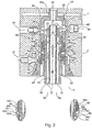
- FIG. 2 now shows one opposite the FIG. 1 or 1a to modified embodiment of a water filter that the blend setting is not done via a radially adjustable relative to the two inlet openings 14 for the main filter section and 15 for the bypass section adjusting ring 7, but via two axially mutually displaceable, coaxially arranged sleeve-shaped elements 39 and 61st ,
- the relative position of the two sleeves 61 and 39, which are provided with passages 62, 63 or openings 44a-h, can be influenced by means of an actuator, here by way of example in the form of a sleeve 38.
- an actuator here by way of example in the form of a sleeve 38.
- the sleeve 38 is suitably connected in the same manner as in the radial blending setting with the setting wheel or the cap 23 for transmitting a rotational movement. Notwithstanding the above-described radial blending adjustment, however, it is adjustable for its longitudinal positioning in accordance with the arrow 43, e.g. by means of a threaded connection 41 between the cap 23 and a shoulder 38a of the sleeve 38th
- the blend setting is realized in this exemplary embodiment stepped.
- the raw water supply via the release of complementary passages 44a-h for the filter section 12 and for the Verismetier 13 is set, preferably in certain mixing ratios.
- the two passages 62 and 63 of the raw water distribution sleeve 61 are each formed equal in size.
- the passageway-engaging complementary openings 44a and 44e, 44b and 44f, 44c and 44g and 44d and 44h are inversely stepped from large to small for 44a-44d and small to large for 44e to 44h, respectively.
- the complementary, coaxial sleeve 39 is formed as a neck of the cartridge 3 and with the above-described, in cross-section preferably each in opposite directions stepped openings 44a-h for the entry of the inflow valve 18 water flowing into the filter section via the channel 12 and provided in the Verismetier via the channel 13.
- the inlet of the water is represented by the individual arrows, which are shown in the chamber 11, the sleeve 61 around flowing around and thus both from the left and right in this sectional view through the respective openings 62 and 63, respectively.
- the outlet of the filtered water is again in accordance with the filter output 29 and here in addition via the passage of an exhaust valve 45. This is controlled by a cam follower 46 through the respective cam 47.
- a preferably central "mandrel" changes its height depending on the position of the so-called bypass adjusting cap 23, and thereby a different number of passages, for example in the form of holes in a correspondingly assigned inlet channel of the filter candle for adjusting the Closes blend ratio.
- such an inlet channel is provided with at least one axially oriented row of holes in the region of the filter plug neck.
- a cam 22 for the control of the flushing or expansion valve 19 and a cam 47 for the control of the outlet valve 45 are shown schematically.
- the outlet valve 45 is to be opened by a cam 47 whenever the cartridge or cartridge is firmly screwed in, the flushing or relief valve should be opened only briefly during the screwing or briefly during the unscrewing when screwing a new filter cartridge this to be able to rinse briefly or, when unscrewing, to allow a pressure relief of the filter 1 via a drain line provided for this purpose.
- To control the intake valve 18 is a lug or cam 79th intended. For example, in the lower neck region of the filter cartridge to actuate the inlet valve 18 during insertion or removal of the cartridge.
- the control of the blend ratio is carried out in this embodiment, as already partially carried out above, by the adjustment of the adjusting wheel 23.
- an axial displacement of the sleeve 38 and as a result, a displacement of the raw water distribution sleeve 61.
- the two filter sections 12, 13 are delimited by the sleeve 40 with respect to the filtration filtrate leaving the filter via the filter outlet 29.
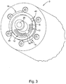
- FIG. 3 shows a perspective top view of a filter cartridge 3 with the front side visible filter outlet 29 and the two inlets 12 to the filter section and 13 to the waste or bypass section.
- the inlet to the filter section 12 and the inlet to the waste section 13 are each through a cover with elongated slots having openings 14 and 15th shown. These can serve, for example, as a coarse filter for supplied in raw water, larger particles.
- two radially aligned key elements 48 are shown, which can ensure, for example, that only for each filter head provided for the filter cartridges can be used.
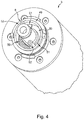
- FIG. 4 shows according to the representation of FIG. 3 in turn, a filter cartridge 3, here supplemented by a Verismeinstellelement 49, which may be associated in this embodiment, for example, the cartridge.
- a Verismeinstellelement 49 which may be associated in this embodiment, for example, the cartridge.
- the Verismeinstellelement but also be associated with the filter head, so that there is a two-part Verismeinstellvorraum, which causes additional security against intentional and / or unintentional manipulation.
- the Verastainstellelement 49 which is also referred to as raw water distribution element is divided into approximately two segments in two passages 50 and two covers 51. Their functioning is achieved by juxtaposing the two Figures 3 and 4 clear.
- a change in the respective effective flow cross-section is effected, in a particularly advantageous manner to the effect that for all Verismeroominwolfen a substantially constant overall effective flow cross-section maintained, and thus a substantially constant internal filter pressure.
- an increase in the effective flow cross section for the filter section 12 and a reduction in the effective flow cross section for the waste section 13 is effected.
- a correspondingly opposite effect is achieved.
- the two drivers 8 each have a fixing element 52, here e.g. shown in the form of a resilient clip element.
- This spring-elastic clip element can be pushed onto a corresponding counterpart when the filter head 2 is fitted with a corresponding filter cartridge 3 and fastened to it via the clamping action.
- This attachment can be designed depending on the embodiment as insoluble or as a detachable attachment. The detachable embodiment can be removed again, for example, by overcoming a corresponding holding resistance.
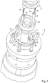
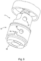
- the FIG. 5 shows a further schematic representation in explosive arrangement of individual elements of the water filter 1.
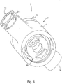
- the FIG. 6 shows a bottom view of a housing 4 of the filter head 2 with schematically illustrated therein Verteninstellelement or raw water distribution element as a complementary part of the partial flow channel guide element, both together the Verteninstellvorraum according to the FIG. 4 form.
- the three ports of the filter head 2 are the inlet 31 for the supply of raw water, the outlet 30 for the flow of the filtrate and the relaxation and Spülauslass 54 for a guided disposal of the discharged via the relaxation or flushing valve water.
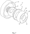
- FIGS. 7 to 9 show further views of individual elements of the water filter 1.
- Die FIG. 7 shows the adjusting cap 23, the adjoining and the rotational movement transmitting Verhowinstellhülse 17 with the opening 27 formed therein for the exit of the filtrate flow in the direction of the outlet 30.
- Versatzinstellhülse 17 coupled via the driver 8 coupled to the Verismeinstellelement 49.
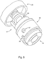
- Another corresponding representation is in the FIG. 8 to see that opposite the FIG. 7 is supplemented by the additional valve body 56 shown.
- This valve body 56 has a valve opening 57 as an inlet valve that can be actuated, for example, by the encryption element 55, which is complementary to the encryption element 48, with respect to an open position or a closed position by rotation when the filter cartridge is screwed in or out.
- the encryption element 55 which is complementary to the encryption element 48
- This valve body 56 can be used or used in various embodiments of filter heads with partly different filter functions. It is thus a multifunctional valve body 56.
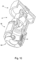
- the FIG. 10 finally shows a sectional view through the elements of the water filter 1 as in the example FIG. 9 are shown.
- the section runs through the driver 8 and the spring element 53 arranged therein, which ensures that the Veritesinstellelement 49 is pressed resiliently in installed in the filter head 2 state of the filter cartridge against the front side of the filter cartridge, so as a proper distribution of raw water flow to the filter section 12 or to enable the blending line 13.
Landscapes
- Chemical & Material Sciences (AREA)
- Life Sciences & Earth Sciences (AREA)
- Hydrology & Water Resources (AREA)
- Engineering & Computer Science (AREA)
- Environmental & Geological Engineering (AREA)
- Water Supply & Treatment (AREA)
- Organic Chemistry (AREA)
- Chemical Kinetics & Catalysis (AREA)
- Water Treatment By Sorption (AREA)
Applications Claiming Priority (4)
| Application Number | Priority Date | Filing Date | Title |
|---|---|---|---|
| DE102006016357 | 2006-04-05 | ||
| DE102006044746.8A DE102006044746B4 (de) | 2006-04-05 | 2006-09-20 | Wasserfilter mit Verschneidevorrichtung |
| DE102007010129.7A DE102007010129B4 (de) | 2006-04-05 | 2007-02-28 | Wasserfilter-Kartuschensystem mit kombinierter Verschneideventiltechnik in der Kerze und Einstellvorrichtung im Kopf |
| PCT/EP2007/003103 WO2007115793A1 (de) | 2006-04-05 | 2007-04-05 | Wasserfilter-kartuschensystem mit kombinierter verschneideventiltechnik in der kerze und einstellvorrichtung im kopf |
Related Child Applications (2)
| Application Number | Title | Priority Date | Filing Date |
|---|---|---|---|
| EP12005603.1 Division-Into | 2012-08-01 | ||
| EP18166547.2 Division-Into | 2018-04-10 |
Publications (2)
| Publication Number | Publication Date |
|---|---|
| EP2007683A1 EP2007683A1 (de) | 2008-12-31 |
| EP2007683B1 true EP2007683B1 (de) | 2018-05-23 |
Family
ID=38222655
Family Applications (1)
| Application Number | Title | Priority Date | Filing Date |
|---|---|---|---|
| EP07724044.8A Active EP2007683B1 (de) | 2006-04-05 | 2007-04-05 | Wasserfilter-kartuschensystem mit kombinierter verschneideventiltechnik und einstellvorrichtung in der kerze und im kopf |
Country Status (4)
| Country | Link |
|---|---|
| US (2) | US8252173B2 (enExample) |
| EP (1) | EP2007683B1 (enExample) |
| JP (1) | JP5689234B2 (enExample) |
| WO (1) | WO2007115793A1 (enExample) |
Families Citing this family (33)
| Publication number | Priority date | Publication date | Assignee | Title |
|---|---|---|---|---|
| EP2007683B1 (de) * | 2006-04-05 | 2018-05-23 | Aquis Wasser-Luft-Systeme GmbH, Lindau | Wasserfilter-kartuschensystem mit kombinierter verschneideventiltechnik und einstellvorrichtung in der kerze und im kopf |
| US9695579B2 (en) | 2011-03-15 | 2017-07-04 | Sloan Valve Company | Automatic faucets |
| CN103459730B (zh) | 2011-03-15 | 2016-04-06 | 仕龙阀门公司 | 自动水龙头 |
| EP2866913B1 (en) * | 2012-06-29 | 2019-05-01 | 3M Innovative Properties Company | Media cartridge with adjustable bypass |
| US9320993B2 (en) | 2012-11-12 | 2016-04-26 | Whirlpool Corporation | Filter housing for small media |
| US9327216B2 (en) | 2012-11-12 | 2016-05-03 | Whirlpool Corporation | Customizable multi-stage water treatment system |
| US9889478B2 (en) | 2012-11-12 | 2018-02-13 | Whirlpool Corporation | Consumable descaling cartridges for a refrigerator appliance |
| US9314716B2 (en) | 2012-11-12 | 2016-04-19 | Whirlpool Corporation | Customizable multi-stage water treatment assembly |
| KR101936742B1 (ko) * | 2012-12-04 | 2019-04-09 | 코웨이 주식회사 | 수처리장치 |
| GB2517504B (en) * | 2013-08-23 | 2016-02-17 | Mann & Hummel Gmbh | Filtration Apparatus |
| JP6538700B2 (ja) | 2013-09-16 | 2019-07-03 | スリーエム イノベイティブ プロパティズ カンパニー | 直線状の調節式バイパスを備えた媒体カートリッジ |
| EP3242734B1 (en) | 2015-01-07 | 2023-08-30 | Brita Se | Liquid treatment cartridge, set of such cartridges and method of manufacturing it |
| EP3078637A1 (en) * | 2015-04-09 | 2016-10-12 | Brita GmbH | Device for forming a head part of a liquid treatment apparatus and liquid treatment apparatus |
| KR101788965B1 (ko) | 2016-03-22 | 2017-10-20 | 엘지전자 주식회사 | 정수장치 및 정수장치가 구비된 냉장고 |
| IT201700061699A1 (it) * | 2017-06-06 | 2018-12-06 | Laica Spa | Dispositivo filtrante a percolazione |
| CN109268508B (zh) | 2018-10-26 | 2020-05-08 | 3M创新有限公司 | 旁通阀及水净化器 |
| US11485647B2 (en) | 2019-05-23 | 2022-11-01 | Bsh Home Appliances Corporation | Changeable water filter in combination with a mixing valve for pretreatment of water in a home appliance and method of pretreating water |
| CN113339433B (zh) * | 2020-03-26 | 2025-03-25 | 阳江核电有限公司 | 核电厂碎石过滤器锁车工具以及方法 |
| USD987772S1 (en) | 2020-07-02 | 2023-05-30 | Qingdao Ecopure Filter Co., Ltd. | Water filter |
| DE102020133106A1 (de) * | 2020-12-11 | 2022-06-15 | Beko Technologies Gmbh | Filtereinheit und Bodeneinheit einer Öl/Wasser-Trennvorrichtung zum Entfernen ölhaltiger Bestandteile aus einem Öl/Wasser-Gemisch |
| USD1001236S1 (en) | 2021-05-28 | 2023-10-10 | Electrolux Home Products, Inc. | Filter cartridge |
| US11779867B2 (en) | 2021-05-28 | 2023-10-10 | Electrolux Home Products, Inc. | Mechanical interlock system for a filter |
| US11872510B2 (en) | 2021-07-01 | 2024-01-16 | Qingdao Ecopure Filter Co., Ltd | Water filter |
| USD1019884S1 (en) | 2021-08-03 | 2024-03-26 | Qingdao Ecopure Filter Co., Ltd. | Water filter |
| USD1016970S1 (en) | 2021-09-03 | 2024-03-05 | Qingdao Ecopure Filter Co., Ltd | Water filter |
| USD1058790S1 (en) | 2023-01-16 | 2025-01-21 | Qingdao Ecopure Filter Co., Ltd. | Water filter |
| USD1072171S1 (en) | 2023-03-17 | 2025-04-22 | Haier Us Appliance Solutions, Inc. | Water filter |
| USD1072176S1 (en) | 2023-03-17 | 2025-04-22 | Haier Us Appliance Solutions, Inc. | Water filter |
| USD1072172S1 (en) | 2023-03-17 | 2025-04-22 | Haier Us Appliance Solutions, Inc. | Water filter |
| USD1072178S1 (en) | 2023-03-17 | 2025-04-22 | Haier Us Appliance Solutions, Inc. | Water filter |
| USD1072175S1 (en) | 2023-03-17 | 2025-04-22 | Haier Us Appliance Solutions, Inc. | Water filter |
| USD1072174S1 (en) | 2023-03-17 | 2025-04-22 | Haier Us Appliance Solutions, Inc. | Water filter |
| USD1072177S1 (en) | 2023-03-17 | 2025-04-22 | Haier Us Appliance Solutions, Inc. | Water filter |
Family Cites Families (30)
| Publication number | Priority date | Publication date | Assignee | Title |
|---|---|---|---|---|
| US3334754A (en) * | 1964-11-23 | 1967-08-08 | Marvel Eng Co | Filter head structure |
| US3456800A (en) * | 1966-12-06 | 1969-07-22 | Wix Corp | Filter structure with alternative inlet and outlet housing openings |
| US4832836A (en) * | 1983-06-14 | 1989-05-23 | Leslie Selsdon | Series filters |
| ATE105203T1 (de) | 1986-01-27 | 1994-05-15 | Cuno Inc | Schnellwechselfilterpatrone und kopf dafuer. |
| US4725354A (en) | 1986-03-07 | 1988-02-16 | Everpure, Inc. | Filtering system |
| US5082557A (en) * | 1990-04-02 | 1992-01-21 | Rainsoft Water Conditioning Co. | Control head for water purifier |
| US5174337A (en) * | 1990-10-31 | 1992-12-29 | Erie Manufacturing Company | Water conditioner rotary valve |
| DE9207977U1 (de) | 1992-06-13 | 1992-11-26 | Leifheit AG, 5408 Nassau | Haushaltswasserfilter |
| US5336406A (en) * | 1993-01-26 | 1994-08-09 | Elkay Manufacturing Company | Replaceable filter cartridge and head assembly with safety shut-off valve |
| DE4422709A1 (de) * | 1994-06-29 | 1996-01-04 | Sheco Ag | Vorrichtung zur Behandlung von kleinen Wassermengen |
| US5591332A (en) | 1995-05-25 | 1997-01-07 | Omnipure Filter Co. | Filter assembly with automatic shut-off and quick-connect filter cartridge |
| JP3585586B2 (ja) * | 1995-07-28 | 2004-11-04 | 松下電器産業株式会社 | 浄水器付混合水栓 |
| JP2715371B2 (ja) * | 1995-12-28 | 1998-02-18 | クリタック株式会社 | 浄水装置 |
| US5826854A (en) * | 1996-06-07 | 1998-10-27 | Amana Refrigeration, Inc. | Fluid routing system |
| US5855777A (en) | 1996-10-31 | 1999-01-05 | Fountainhead Technologies, Inc. | Multi-chamber water purification device and method of using the same |
| DE19648405A1 (de) | 1996-11-22 | 1998-10-15 | Brita Wasserfilter | Anschlußeinheit für Großgeräte-Wasserfilter |
| DE19827623A1 (de) | 1997-07-04 | 1999-01-07 | Aweco Kunststofftech Geraete | Wasserbehälter mit Filterpatrone |
| US6042729A (en) | 1998-02-18 | 2000-03-28 | Chau; Yiu Chau | Regeneration of water treatment media |
| DE19958648A1 (de) * | 1999-12-06 | 2001-06-07 | Brita Gmbh | Wasserfiltervorrichtung |
| US6949189B2 (en) * | 2000-04-20 | 2005-09-27 | Cuno Incorporated | Keyed filter assembly |
| US6458269B1 (en) | 2000-04-20 | 2002-10-01 | Cuno Incorporated | Keyed filter assembly |
| US6436282B1 (en) * | 2000-08-08 | 2002-08-20 | Plymouth Products, Inc. | Flow control module for RO water treatment system |
| US6800200B2 (en) * | 2002-04-18 | 2004-10-05 | Cuno Incorporated | Dual-flow filter cartridge |
| DE10231096B9 (de) * | 2002-07-10 | 2006-11-09 | Brita Gmbh | Filtervorrichtung und Innenbehälter für eine Filtervorrichtung |
| US6923910B2 (en) * | 2003-01-07 | 2005-08-02 | Cuno Incorporated | Filter cartridge having bypass feature |
| DE102004049877B4 (de) | 2004-10-13 | 2008-03-27 | Brita Gmbh | Filterkartusche und Sitzelement für eine Filterkartusche |
| DE102004049876C5 (de) | 2004-10-13 | 2010-04-29 | Brita Gmbh | Filterkartusche |
| CN2741960Y (zh) * | 2004-10-28 | 2005-11-23 | 厦门建霖卫浴工业有限公司 | 净水器 |
| KR100712266B1 (ko) * | 2005-03-24 | 2007-05-17 | 주식회사 피코그램 | 커넥터를 이용하여 용이하게 교체되는 정수용 필터, 및 이를 이용한 정수장치 |
| EP2007683B1 (de) * | 2006-04-05 | 2018-05-23 | Aquis Wasser-Luft-Systeme GmbH, Lindau | Wasserfilter-kartuschensystem mit kombinierter verschneideventiltechnik und einstellvorrichtung in der kerze und im kopf |
-
2007
- 2007-04-05 EP EP07724044.8A patent/EP2007683B1/de active Active
- 2007-04-05 JP JP2009503493A patent/JP5689234B2/ja not_active Expired - Fee Related
- 2007-04-05 US US12/226,005 patent/US8252173B2/en active Active
- 2007-04-05 WO PCT/EP2007/003103 patent/WO2007115793A1/de not_active Ceased
-
2012
- 2012-08-27 US US13/573,147 patent/US8505741B2/en active Active
Non-Patent Citations (1)
| Title |
|---|
| None * |
Also Published As
| Publication number | Publication date |
|---|---|
| JP2009532199A (ja) | 2009-09-10 |
| JP5689234B2 (ja) | 2015-03-25 |
| US20090173675A1 (en) | 2009-07-09 |
| US8252173B2 (en) | 2012-08-28 |
| EP2007683A1 (de) | 2008-12-31 |
| US20120325732A1 (en) | 2012-12-27 |
| US8505741B2 (en) | 2013-08-13 |
| WO2007115793A1 (de) | 2007-10-18 |
Similar Documents
| Publication | Publication Date | Title |
|---|---|---|
| EP2007683B1 (de) | Wasserfilter-kartuschensystem mit kombinierter verschneideventiltechnik und einstellvorrichtung in der kerze und im kopf | |
| EP2749336B1 (de) | Wasserfiltervorrichtung mit Verschlüsselungsstruktur | |
| EP2102484B1 (de) | Kraftstofffilter eines fahrzeug-verbrennungsmotors | |
| EP1751061B9 (de) | Filterkartusche und vorrichtung zur filtration von flüssigkeiten | |
| DE3991109C2 (de) | Mischventil mit Druckausgleichsvorrichtung | |
| DE69920818T2 (de) | Sequentieller mischplattenschieber | |
| DE60319751T2 (de) | Thermostatisches mischventil | |
| EP1654049B1 (de) | Vorrichtung zum abtrennen von verunreinigungen aus dem schmieröl einer brennkraftmaschine | |
| WO2008077622A2 (de) | Wasserfiltervorrichtung mit stellorgan zur einstellung eines verschnittverhältnisses | |
| DE102010025153A1 (de) | Schaltvorrichtung für einen Fluidstrom | |
| EP2054132A1 (de) | Ölfilteranordnung und filterelement hierfür | |
| EP2864016A2 (de) | Flüssigkeitsfilter mit einem filterumgehungsventil und einem zentralen ablasskanal und filtereinsatz für einen flüssigkeitsfilter | |
| DE102007010129B4 (de) | Wasserfilter-Kartuschensystem mit kombinierter Verschneideventiltechnik in der Kerze und Einstellvorrichtung im Kopf | |
| EP2043752A1 (de) | Ölfilteranordnung | |
| DE19812049B4 (de) | Flüssigkeitsventil | |
| DE202013100346U1 (de) | Rückspülbarer Flüssigkeitsfilter | |
| EP0501953B1 (de) | Sanitäre mischbatterie | |
| WO2013107616A1 (de) | Sanitärarmatur | |
| DE102006044746B4 (de) | Wasserfilter mit Verschneidevorrichtung | |
| EP1130223A1 (de) | Flüssigkeitsfilter, insbesondere Ölfilter für eine Brennkraftmaschine | |
| DE69805603T2 (de) | Thermostatisches mischventil | |
| EP3535039A1 (de) | Filtereinrichtung | |
| DE102011081064B4 (de) | Scheibensteuerung | |
| DE102016104411A1 (de) | Ventileinsatz für ein Heizkörperventil und Heizkörper mit Heizkörperventil |
Legal Events
| Date | Code | Title | Description |
|---|---|---|---|
| PUAI | Public reference made under article 153(3) epc to a published international application that has entered the european phase |
Free format text: ORIGINAL CODE: 0009012 |
|
| 17P | Request for examination filed |
Effective date: 20081030 |
|
| AK | Designated contracting states |
Kind code of ref document: A1 Designated state(s): AT BE BG CH CY CZ DE DK EE ES FI FR GB GR HU IE IS IT LI LT LU LV MC MT NL PL PT RO SE SI SK TR |
|
| AX | Request for extension of the european patent |
Extension state: AL BA HR MK RS |
|
| DAX | Request for extension of the european patent (deleted) | ||
| 17Q | First examination report despatched |
Effective date: 20130118 |
|
| GRAP | Despatch of communication of intention to grant a patent |
Free format text: ORIGINAL CODE: EPIDOSNIGR1 |
|
| STAA | Information on the status of an ep patent application or granted ep patent |
Free format text: STATUS: GRANT OF PATENT IS INTENDED |
|
| INTG | Intention to grant announced |
Effective date: 20180103 |
|
| GRAS | Grant fee paid |
Free format text: ORIGINAL CODE: EPIDOSNIGR3 |
|
| GRAA | (expected) grant |
Free format text: ORIGINAL CODE: 0009210 |
|
| STAA | Information on the status of an ep patent application or granted ep patent |
Free format text: STATUS: THE PATENT HAS BEEN GRANTED |
|
| AK | Designated contracting states |
Kind code of ref document: B1 Designated state(s): AT BE BG CH CY CZ DE DK EE ES FI FR GB GR HU IE IS IT LI LT LU LV MC MT NL PL PT RO SE SI SK TR |
|
| REG | Reference to a national code |
Ref country code: GB Ref legal event code: FG4D Free format text: NOT ENGLISH |
|
| REG | Reference to a national code |
Ref country code: CH Ref legal event code: EP |
|
| REG | Reference to a national code |
Ref country code: IE Ref legal event code: FG4D Free format text: LANGUAGE OF EP DOCUMENT: GERMAN |
|
| REG | Reference to a national code |
Ref country code: AT Ref legal event code: REF Ref document number: 1001382 Country of ref document: AT Kind code of ref document: T Effective date: 20180615 |
|
| REG | Reference to a national code |
Ref country code: DE Ref legal event code: R096 Ref document number: 502007016189 Country of ref document: DE |
|
| REG | Reference to a national code |
Ref country code: NL Ref legal event code: FP |
|
| REG | Reference to a national code |
Ref country code: LT Ref legal event code: MG4D |
|
| PG25 | Lapsed in a contracting state [announced via postgrant information from national office to epo] |
Ref country code: ES Free format text: LAPSE BECAUSE OF FAILURE TO SUBMIT A TRANSLATION OF THE DESCRIPTION OR TO PAY THE FEE WITHIN THE PRESCRIBED TIME-LIMIT Effective date: 20180523 Ref country code: SE Free format text: LAPSE BECAUSE OF FAILURE TO SUBMIT A TRANSLATION OF THE DESCRIPTION OR TO PAY THE FEE WITHIN THE PRESCRIBED TIME-LIMIT Effective date: 20180523 Ref country code: FI Free format text: LAPSE BECAUSE OF FAILURE TO SUBMIT A TRANSLATION OF THE DESCRIPTION OR TO PAY THE FEE WITHIN THE PRESCRIBED TIME-LIMIT Effective date: 20180523 Ref country code: LT Free format text: LAPSE BECAUSE OF FAILURE TO SUBMIT A TRANSLATION OF THE DESCRIPTION OR TO PAY THE FEE WITHIN THE PRESCRIBED TIME-LIMIT Effective date: 20180523 Ref country code: BG Free format text: LAPSE BECAUSE OF FAILURE TO SUBMIT A TRANSLATION OF THE DESCRIPTION OR TO PAY THE FEE WITHIN THE PRESCRIBED TIME-LIMIT Effective date: 20180823 |
|
| PG25 | Lapsed in a contracting state [announced via postgrant information from national office to epo] |
Ref country code: GR Free format text: LAPSE BECAUSE OF FAILURE TO SUBMIT A TRANSLATION OF THE DESCRIPTION OR TO PAY THE FEE WITHIN THE PRESCRIBED TIME-LIMIT Effective date: 20180824 Ref country code: LV Free format text: LAPSE BECAUSE OF FAILURE TO SUBMIT A TRANSLATION OF THE DESCRIPTION OR TO PAY THE FEE WITHIN THE PRESCRIBED TIME-LIMIT Effective date: 20180523 |
|
| PG25 | Lapsed in a contracting state [announced via postgrant information from national office to epo] |
Ref country code: CZ Free format text: LAPSE BECAUSE OF FAILURE TO SUBMIT A TRANSLATION OF THE DESCRIPTION OR TO PAY THE FEE WITHIN THE PRESCRIBED TIME-LIMIT Effective date: 20180523 Ref country code: RO Free format text: LAPSE BECAUSE OF FAILURE TO SUBMIT A TRANSLATION OF THE DESCRIPTION OR TO PAY THE FEE WITHIN THE PRESCRIBED TIME-LIMIT Effective date: 20180523 Ref country code: SK Free format text: LAPSE BECAUSE OF FAILURE TO SUBMIT A TRANSLATION OF THE DESCRIPTION OR TO PAY THE FEE WITHIN THE PRESCRIBED TIME-LIMIT Effective date: 20180523 Ref country code: EE Free format text: LAPSE BECAUSE OF FAILURE TO SUBMIT A TRANSLATION OF THE DESCRIPTION OR TO PAY THE FEE WITHIN THE PRESCRIBED TIME-LIMIT Effective date: 20180523 Ref country code: DK Free format text: LAPSE BECAUSE OF FAILURE TO SUBMIT A TRANSLATION OF THE DESCRIPTION OR TO PAY THE FEE WITHIN THE PRESCRIBED TIME-LIMIT Effective date: 20180523 Ref country code: PL Free format text: LAPSE BECAUSE OF FAILURE TO SUBMIT A TRANSLATION OF THE DESCRIPTION OR TO PAY THE FEE WITHIN THE PRESCRIBED TIME-LIMIT Effective date: 20180523 |
|
| REG | Reference to a national code |
Ref country code: DE Ref legal event code: R097 Ref document number: 502007016189 Country of ref document: DE |
|
| PLBE | No opposition filed within time limit |
Free format text: ORIGINAL CODE: 0009261 |
|
| STAA | Information on the status of an ep patent application or granted ep patent |
Free format text: STATUS: NO OPPOSITION FILED WITHIN TIME LIMIT |
|
| 26N | No opposition filed |
Effective date: 20190226 |
|
| PG25 | Lapsed in a contracting state [announced via postgrant information from national office to epo] |
Ref country code: SI Free format text: LAPSE BECAUSE OF FAILURE TO SUBMIT A TRANSLATION OF THE DESCRIPTION OR TO PAY THE FEE WITHIN THE PRESCRIBED TIME-LIMIT Effective date: 20180523 |
|
| PG25 | Lapsed in a contracting state [announced via postgrant information from national office to epo] |
Ref country code: LU Free format text: LAPSE BECAUSE OF NON-PAYMENT OF DUE FEES Effective date: 20190405 Ref country code: MC Free format text: LAPSE BECAUSE OF FAILURE TO SUBMIT A TRANSLATION OF THE DESCRIPTION OR TO PAY THE FEE WITHIN THE PRESCRIBED TIME-LIMIT Effective date: 20180523 |
|
| PG25 | Lapsed in a contracting state [announced via postgrant information from national office to epo] |
Ref country code: TR Free format text: LAPSE BECAUSE OF FAILURE TO SUBMIT A TRANSLATION OF THE DESCRIPTION OR TO PAY THE FEE WITHIN THE PRESCRIBED TIME-LIMIT Effective date: 20180523 |
|
| PG25 | Lapsed in a contracting state [announced via postgrant information from national office to epo] |
Ref country code: IE Free format text: LAPSE BECAUSE OF NON-PAYMENT OF DUE FEES Effective date: 20190405 |
|
| PG25 | Lapsed in a contracting state [announced via postgrant information from national office to epo] |
Ref country code: PT Free format text: LAPSE BECAUSE OF FAILURE TO SUBMIT A TRANSLATION OF THE DESCRIPTION OR TO PAY THE FEE WITHIN THE PRESCRIBED TIME-LIMIT Effective date: 20180924 |
|
| PG25 | Lapsed in a contracting state [announced via postgrant information from national office to epo] |
Ref country code: CY Free format text: LAPSE BECAUSE OF FAILURE TO SUBMIT A TRANSLATION OF THE DESCRIPTION OR TO PAY THE FEE WITHIN THE PRESCRIBED TIME-LIMIT Effective date: 20180523 |
|
| PG25 | Lapsed in a contracting state [announced via postgrant information from national office to epo] |
Ref country code: IS Free format text: LAPSE BECAUSE OF FAILURE TO SUBMIT A TRANSLATION OF THE DESCRIPTION OR TO PAY THE FEE WITHIN THE PRESCRIBED TIME-LIMIT Effective date: 20180923 |
|
| PG25 | Lapsed in a contracting state [announced via postgrant information from national office to epo] |
Ref country code: MT Free format text: LAPSE BECAUSE OF FAILURE TO SUBMIT A TRANSLATION OF THE DESCRIPTION OR TO PAY THE FEE WITHIN THE PRESCRIBED TIME-LIMIT Effective date: 20180523 Ref country code: HU Free format text: LAPSE BECAUSE OF FAILURE TO SUBMIT A TRANSLATION OF THE DESCRIPTION OR TO PAY THE FEE WITHIN THE PRESCRIBED TIME-LIMIT; INVALID AB INITIO Effective date: 20070405 |
|
| PGFP | Annual fee paid to national office [announced via postgrant information from national office to epo] |
Ref country code: IT Payment date: 20230428 Year of fee payment: 17 Ref country code: FR Payment date: 20230417 Year of fee payment: 17 |
|
| PG25 | Lapsed in a contracting state [announced via postgrant information from national office to epo] |
Ref country code: FR Free format text: LAPSE BECAUSE OF NON-PAYMENT OF DUE FEES Effective date: 20240430 |
|
| PG25 | Lapsed in a contracting state [announced via postgrant information from national office to epo] |
Ref country code: FR Free format text: LAPSE BECAUSE OF NON-PAYMENT OF DUE FEES Effective date: 20240430 |
|
| REG | Reference to a national code |
Ref country code: DE Ref legal event code: R082 Ref document number: 502007016189 Country of ref document: DE Representative=s name: RAVENSPAT PATENTANWAELTE PARTNERSCHAFT MBB, DE |
|
| PG25 | Lapsed in a contracting state [announced via postgrant information from national office to epo] |
Ref country code: IT Free format text: LAPSE BECAUSE OF NON-PAYMENT OF DUE FEES Effective date: 20240405 |
|
| PGFP | Annual fee paid to national office [announced via postgrant information from national office to epo] |
Ref country code: NL Payment date: 20250422 Year of fee payment: 19 |
|
| PGFP | Annual fee paid to national office [announced via postgrant information from national office to epo] |
Ref country code: DE Payment date: 20250417 Year of fee payment: 19 |
|
| PGFP | Annual fee paid to national office [announced via postgrant information from national office to epo] |
Ref country code: GB Payment date: 20250423 Year of fee payment: 19 |
|
| PGFP | Annual fee paid to national office [announced via postgrant information from national office to epo] |
Ref country code: BE Payment date: 20250422 Year of fee payment: 19 |
|
| PGFP | Annual fee paid to national office [announced via postgrant information from national office to epo] |
Ref country code: CH Payment date: 20250501 Year of fee payment: 19 |
|
| PGFP | Annual fee paid to national office [announced via postgrant information from national office to epo] |
Ref country code: AT Payment date: 20250416 Year of fee payment: 19 |