EP2007503B1 - Vakuum/druckwechseladsorptionsverfahren zur wiedergewinnung von hochreinem kohlendioxid - Google Patents
Vakuum/druckwechseladsorptionsverfahren zur wiedergewinnung von hochreinem kohlendioxid Download PDFInfo
- Publication number
- EP2007503B1 EP2007503B1 EP07754299.1A EP07754299A EP2007503B1 EP 2007503 B1 EP2007503 B1 EP 2007503B1 EP 07754299 A EP07754299 A EP 07754299A EP 2007503 B1 EP2007503 B1 EP 2007503B1
- Authority
- EP
- European Patent Office
- Prior art keywords
- pressure
- adsorption bed
- pressure range
- feed flow
- feed
- Prior art date
- Legal status (The legal status is an assumption and is not a legal conclusion. Google has not performed a legal analysis and makes no representation as to the accuracy of the status listed.)
- Not-in-force
Links
Images


Classifications
-
- B—PERFORMING OPERATIONS; TRANSPORTING
- B01—PHYSICAL OR CHEMICAL PROCESSES OR APPARATUS IN GENERAL
- B01D—SEPARATION
- B01D53/00—Separation of gases or vapours; Recovering vapours of volatile solvents from gases; Chemical or biological purification of waste gases, e.g. engine exhaust gases, smoke, fumes, flue gases, aerosols
- B01D53/02—Separation of gases or vapours; Recovering vapours of volatile solvents from gases; Chemical or biological purification of waste gases, e.g. engine exhaust gases, smoke, fumes, flue gases, aerosols by adsorption, e.g. preparative gas chromatography
- B01D53/04—Separation of gases or vapours; Recovering vapours of volatile solvents from gases; Chemical or biological purification of waste gases, e.g. engine exhaust gases, smoke, fumes, flue gases, aerosols by adsorption, e.g. preparative gas chromatography with stationary adsorbents
- B01D53/047—Pressure swing adsorption
- B01D53/0476—Vacuum pressure swing adsorption
-
- B—PERFORMING OPERATIONS; TRANSPORTING
- B01—PHYSICAL OR CHEMICAL PROCESSES OR APPARATUS IN GENERAL
- B01D—SEPARATION
- B01D53/00—Separation of gases or vapours; Recovering vapours of volatile solvents from gases; Chemical or biological purification of waste gases, e.g. engine exhaust gases, smoke, fumes, flue gases, aerosols
- B01D53/02—Separation of gases or vapours; Recovering vapours of volatile solvents from gases; Chemical or biological purification of waste gases, e.g. engine exhaust gases, smoke, fumes, flue gases, aerosols by adsorption, e.g. preparative gas chromatography
- B01D53/04—Separation of gases or vapours; Recovering vapours of volatile solvents from gases; Chemical or biological purification of waste gases, e.g. engine exhaust gases, smoke, fumes, flue gases, aerosols by adsorption, e.g. preparative gas chromatography with stationary adsorbents
- B01D53/047—Pressure swing adsorption
-
- C—CHEMISTRY; METALLURGY
- C01—INORGANIC CHEMISTRY
- C01B—NON-METALLIC ELEMENTS; COMPOUNDS THEREOF; METALLOIDS OR COMPOUNDS THEREOF NOT COVERED BY SUBCLASS C01C
- C01B3/00—Hydrogen; Gaseous mixtures containing hydrogen; Separation of hydrogen from mixtures containing it; Purification of hydrogen; Reversible storage of hydrogen
- C01B3/50—Separation of hydrogen or hydrogen-containing gases from gaseous mixtures, e.g. purification
- C01B3/56—Separation of hydrogen or hydrogen-containing gases from gaseous mixtures, e.g. purification by contacting with solids; Regeneration of used solids
-
- B—PERFORMING OPERATIONS; TRANSPORTING
- B01—PHYSICAL OR CHEMICAL PROCESSES OR APPARATUS IN GENERAL
- B01D—SEPARATION
- B01D2253/00—Adsorbents used in seperation treatment of gases and vapours
- B01D2253/10—Inorganic adsorbents
-
- B—PERFORMING OPERATIONS; TRANSPORTING
- B01—PHYSICAL OR CHEMICAL PROCESSES OR APPARATUS IN GENERAL
- B01D—SEPARATION
- B01D2253/00—Adsorbents used in seperation treatment of gases and vapours
- B01D2253/10—Inorganic adsorbents
- B01D2253/106—Silica or silicates
-
- B—PERFORMING OPERATIONS; TRANSPORTING
- B01—PHYSICAL OR CHEMICAL PROCESSES OR APPARATUS IN GENERAL
- B01D—SEPARATION
- B01D2256/00—Main component in the product gas stream after treatment
- B01D2256/16—Hydrogen
-
- B—PERFORMING OPERATIONS; TRANSPORTING
- B01—PHYSICAL OR CHEMICAL PROCESSES OR APPARATUS IN GENERAL
- B01D—SEPARATION
- B01D2256/00—Main component in the product gas stream after treatment
- B01D2256/22—Carbon dioxide
-
- B—PERFORMING OPERATIONS; TRANSPORTING
- B01—PHYSICAL OR CHEMICAL PROCESSES OR APPARATUS IN GENERAL
- B01D—SEPARATION
- B01D2257/00—Components to be removed
- B01D2257/50—Carbon oxides
- B01D2257/504—Carbon dioxide
-
- B—PERFORMING OPERATIONS; TRANSPORTING
- B01—PHYSICAL OR CHEMICAL PROCESSES OR APPARATUS IN GENERAL
- B01D—SEPARATION
- B01D2257/00—Components to be removed
- B01D2257/80—Water
-
- B—PERFORMING OPERATIONS; TRANSPORTING
- B01—PHYSICAL OR CHEMICAL PROCESSES OR APPARATUS IN GENERAL
- B01D—SEPARATION
- B01D2259/00—Type of treatment
- B01D2259/40—Further details for adsorption processes and devices
- B01D2259/40011—Methods relating to the process cycle in pressure or temperature swing adsorption
- B01D2259/40058—Number of sequence steps, including sub-steps, per cycle
- B01D2259/40069—Eight
-
- B—PERFORMING OPERATIONS; TRANSPORTING
- B01—PHYSICAL OR CHEMICAL PROCESSES OR APPARATUS IN GENERAL
- B01D—SEPARATION
- B01D2259/00—Type of treatment
- B01D2259/40—Further details for adsorption processes and devices
- B01D2259/40011—Methods relating to the process cycle in pressure or temperature swing adsorption
- B01D2259/40058—Number of sequence steps, including sub-steps, per cycle
- B01D2259/40073—Ten
-
- B—PERFORMING OPERATIONS; TRANSPORTING
- B01—PHYSICAL OR CHEMICAL PROCESSES OR APPARATUS IN GENERAL
- B01D—SEPARATION
- B01D2259/00—Type of treatment
- B01D2259/40—Further details for adsorption processes and devices
- B01D2259/40011—Methods relating to the process cycle in pressure or temperature swing adsorption
- B01D2259/40058—Number of sequence steps, including sub-steps, per cycle
- B01D2259/40075—More than ten
-
- B—PERFORMING OPERATIONS; TRANSPORTING
- B01—PHYSICAL OR CHEMICAL PROCESSES OR APPARATUS IN GENERAL
- B01D—SEPARATION
- B01D2259/00—Type of treatment
- B01D2259/40—Further details for adsorption processes and devices
- B01D2259/406—Further details for adsorption processes and devices using more than four beds
- B01D2259/4062—Further details for adsorption processes and devices using more than four beds using six beds
-
- C—CHEMISTRY; METALLURGY
- C01—INORGANIC CHEMISTRY
- C01B—NON-METALLIC ELEMENTS; COMPOUNDS THEREOF; METALLOIDS OR COMPOUNDS THEREOF NOT COVERED BY SUBCLASS C01C
- C01B2203/00—Integrated processes for the production of hydrogen or synthesis gas
- C01B2203/02—Processes for making hydrogen or synthesis gas
- C01B2203/0205—Processes for making hydrogen or synthesis gas containing a reforming step
- C01B2203/0227—Processes for making hydrogen or synthesis gas containing a reforming step containing a catalytic reforming step
- C01B2203/0233—Processes for making hydrogen or synthesis gas containing a reforming step containing a catalytic reforming step the reforming step being a steam reforming step
-
- C—CHEMISTRY; METALLURGY
- C01—INORGANIC CHEMISTRY
- C01B—NON-METALLIC ELEMENTS; COMPOUNDS THEREOF; METALLOIDS OR COMPOUNDS THEREOF NOT COVERED BY SUBCLASS C01C
- C01B2203/00—Integrated processes for the production of hydrogen or synthesis gas
- C01B2203/02—Processes for making hydrogen or synthesis gas
- C01B2203/0283—Processes for making hydrogen or synthesis gas containing a CO-shift step, i.e. a water gas shift step
-
- C—CHEMISTRY; METALLURGY
- C01—INORGANIC CHEMISTRY
- C01B—NON-METALLIC ELEMENTS; COMPOUNDS THEREOF; METALLOIDS OR COMPOUNDS THEREOF NOT COVERED BY SUBCLASS C01C
- C01B2203/00—Integrated processes for the production of hydrogen or synthesis gas
- C01B2203/04—Integrated processes for the production of hydrogen or synthesis gas containing a purification step for the hydrogen or the synthesis gas
- C01B2203/042—Purification by adsorption on solids
- C01B2203/043—Regenerative adsorption process in two or more beds, one for adsorption, the other for regeneration
-
- C—CHEMISTRY; METALLURGY
- C01—INORGANIC CHEMISTRY
- C01B—NON-METALLIC ELEMENTS; COMPOUNDS THEREOF; METALLOIDS OR COMPOUNDS THEREOF NOT COVERED BY SUBCLASS C01C
- C01B2203/00—Integrated processes for the production of hydrogen or synthesis gas
- C01B2203/04—Integrated processes for the production of hydrogen or synthesis gas containing a purification step for the hydrogen or the synthesis gas
- C01B2203/0465—Composition of the impurity
- C01B2203/0475—Composition of the impurity the impurity being carbon dioxide
-
- C—CHEMISTRY; METALLURGY
- C01—INORGANIC CHEMISTRY
- C01B—NON-METALLIC ELEMENTS; COMPOUNDS THEREOF; METALLOIDS OR COMPOUNDS THEREOF NOT COVERED BY SUBCLASS C01C
- C01B2203/00—Integrated processes for the production of hydrogen or synthesis gas
- C01B2203/08—Methods of heating or cooling
- C01B2203/0805—Methods of heating the process for making hydrogen or synthesis gas
- C01B2203/0811—Methods of heating the process for making hydrogen or synthesis gas by combustion of fuel
- C01B2203/0827—Methods of heating the process for making hydrogen or synthesis gas by combustion of fuel at least part of the fuel being a recycle stream
-
- C—CHEMISTRY; METALLURGY
- C01—INORGANIC CHEMISTRY
- C01B—NON-METALLIC ELEMENTS; COMPOUNDS THEREOF; METALLOIDS OR COMPOUNDS THEREOF NOT COVERED BY SUBCLASS C01C
- C01B2203/00—Integrated processes for the production of hydrogen or synthesis gas
- C01B2203/80—Aspect of integrated processes for the production of hydrogen or synthesis gas not covered by groups C01B2203/02 - C01B2203/1695
- C01B2203/86—Carbon dioxide sequestration
-
- Y—GENERAL TAGGING OF NEW TECHNOLOGICAL DEVELOPMENTS; GENERAL TAGGING OF CROSS-SECTIONAL TECHNOLOGIES SPANNING OVER SEVERAL SECTIONS OF THE IPC; TECHNICAL SUBJECTS COVERED BY FORMER USPC CROSS-REFERENCE ART COLLECTIONS [XRACs] AND DIGESTS
- Y02—TECHNOLOGIES OR APPLICATIONS FOR MITIGATION OR ADAPTATION AGAINST CLIMATE CHANGE
- Y02C—CAPTURE, STORAGE, SEQUESTRATION OR DISPOSAL OF GREENHOUSE GASES [GHG]
- Y02C20/00—Capture or disposal of greenhouse gases
- Y02C20/40—Capture or disposal of greenhouse gases of CO2
-
- Y—GENERAL TAGGING OF NEW TECHNOLOGICAL DEVELOPMENTS; GENERAL TAGGING OF CROSS-SECTIONAL TECHNOLOGIES SPANNING OVER SEVERAL SECTIONS OF THE IPC; TECHNICAL SUBJECTS COVERED BY FORMER USPC CROSS-REFERENCE ART COLLECTIONS [XRACs] AND DIGESTS
- Y02—TECHNOLOGIES OR APPLICATIONS FOR MITIGATION OR ADAPTATION AGAINST CLIMATE CHANGE
- Y02P—CLIMATE CHANGE MITIGATION TECHNOLOGIES IN THE PRODUCTION OR PROCESSING OF GOODS
- Y02P20/00—Technologies relating to chemical industry
- Y02P20/151—Reduction of greenhouse gas [GHG] emissions, e.g. CO2
-
- Y—GENERAL TAGGING OF NEW TECHNOLOGICAL DEVELOPMENTS; GENERAL TAGGING OF CROSS-SECTIONAL TECHNOLOGIES SPANNING OVER SEVERAL SECTIONS OF THE IPC; TECHNICAL SUBJECTS COVERED BY FORMER USPC CROSS-REFERENCE ART COLLECTIONS [XRACs] AND DIGESTS
- Y02—TECHNOLOGIES OR APPLICATIONS FOR MITIGATION OR ADAPTATION AGAINST CLIMATE CHANGE
- Y02P—CLIMATE CHANGE MITIGATION TECHNOLOGIES IN THE PRODUCTION OR PROCESSING OF GOODS
- Y02P30/00—Technologies relating to oil refining and petrochemical industry
Definitions
- the present invention generally relates to vacuum pressure swing adsorption (VPSA) processes and apparatus to recover CO 2 having a purity of approximately ⁇ 90 mole% from streams containing at least CO 2 and H 2 (e.g., syngas).
- the feed to the CO 2 VPSA unit can be at super ambient pressure.
- the CO 2 VPSA unit produces three streams, a H 2 -enriched stream, a H 2 -depleted stream and a CO 2 product stream.
- SMR Steam methane reforming
- typical product gas has a pressure of between about 689,5 to 3447,4 kPa (100-500 psia), a temperature of between about 15,6 to 65,6 °C (60-150 °F), and a composition of 60-80 mole% H 2 , 15-25 mole% CO 2 , 0.1-5 mole% CO, 3-7 mole% CH 4 , 0-5 mole% N 2 and is saturated with water.
- This gas mixture can then be fed to a pressure swing adsorption (PSA) unit to produce high purity H 2 (e.g., H 2 at a purity of at least 99%).
- PSA pressure swing adsorption
- an amine unit is placed between the shift reactor and the H 2 PSA unit to extract CO 2 from the stream produced by the shift reactor. This process, however, is energy intensive. In addition, amine units can be difficult to operate and are known to have operational problems, such as corrosion, loss of fluid and the like.
- U.S. Patent No. 4,171,206 relates to production of high purity CO 2 and high purity H 2 at high CO 2 recovery from SMR off-gas.
- This patent discloses two trains of adsorption beds, which are in communication with each other during the feed and repressurization steps. Beds in the CO 2 train employ a rinse step by high purity CO 2 at high pressure. Depressurization and evacuation of the same bed follow this step. Depressurized gas is recompressed and used for high-pressure rinse. The effluent from the high pressure, high purity rinse step is recycled to the feed.
- U.S. Patent No. 4,299,596 relates to the production of two products at high purity by employing two trains of beds, which are integrated during the feed and co-current depressurization steps.
- the train producing the more strongly adsorbed species is purged by the co-current depressurized gas after it has been recompressed. Part of the co-current depressurized gas may be recycled for re-pressurization. Evacuation and blowdown steps produce part of the more strongly adsorbed species and part of the purge gas.
- U.S. Patent No. 4,770,676 relates to the production of methane and CO 2 from landfill gas. It is an integrated thermal (TSA) and pressure swing adsorption (PSA) process. The waste produced from the PSA regenerates the TSA.
- TSA integrated thermal
- PSA pressure swing adsorption
- U.S. Patent No. 4,840,647 relates to production of ⁇ 95% CO 2 from a feed stream containing 10-30% CO 2 at ambient pressure.
- the process steps are feed, co-current evacuation, countercurrent evacuation to produce product and a repressurization step.
- Co-current evacuated gas is used for pressure equalizations/repressurization and mixed with the feed.
- U.S. Patent No. 4,857,083 considers production of CO 2 from a gas mixture.
- the discharge end of the feed column is connected with the inlet end of the evacuated bed to reduce the pressure in this bed. Carbon dioxide is then produced by evacuation. This is followed by pressure build up steps.
- U.S. Patent No. 4,913,709 relates to the production of two products at high purity.
- the reference suggests the use of two trains of beds, which are integrated during the feed and re-pressurization steps.
- the train producing the more strongly adsorbed species is purged by the more strongly adsorbed species obtained during the evacuation step. This purge is at low pressure and is carried out after the bed has been depressurized. Effluent during the purge step is recompressed and recycled as feed.
- U.S. Patent No. 4,915,711 discloses production of two products at high purity using a single train of beds. The bed is purged by the more strongly adsorbed species obtained during the evacuation step. This purge is at low pressure and is carried out after the bed has been depressurized. Effluent during the purge step and depressurization step is recompressed and recycled as feed.
- U.S. Patent No. 5,026,406 discloses the production of two products at high purity by employing a single train of beds. The bed is purged by the more strongly adsorbed species obtained during the evacuation step. This purge is at low pressure and is carried out after the bed has been depressurized. Effluent during the purge step and depressurization step is recompressed and recycled as feed.
- U.S. Patent No. 5,051,115 produces a more strongly adsorbed species from a gas mixture at high purity.
- a co-current purge step is employed by the high purity strongly adsorbed species. This purge stream and product are obtained during the evacuation step. Effluent from the purge step is recycled for repressurization.
- U.S. Patent No. 6,245,127 discusses production of CO 2 from a low-pressure gas mixture at constant purity. It employs simultaneous purge and evacuation steps. The countercurrent purge is carried out by the less strongly adsorbed species.
- the present invention generally relates to vacuum pressure swing adsorption (VPSA) processes and apparatus to recover CO 2 having a purity of approximately ⁇ 90 mole% from streams containing at least CO 2 and H 2 (e.g., syngas).
- the feed to the CO 2 VPSA unit can be at super ambient pressure.
- the CO 2 VPSA unit produces three streams, a H 2 -enriched stream, a H 2 -depleted stream and a CO 2 product stream.
- the invention is set forth in the claims.
- Carbon dioxide produced in accordance with the present invention may be used for any desired purpose.
- CO 2 produced as described herein can be used for liquefaction to produce food-grade quality product(s), supercritical CO 2 for enhanced oil recovery or simply CO 2 for sequestration to avoid additional green house gases in the atmosphere in order to satisfy regulatory requirements.
- H 2 recovery is expected to be increased by extracting CO 2 , thereby increasing H 2 partial pressure in the H 2 PSA feed stream.
- the recovered CO 2 can be further upgraded, sequestered or used in applications such as enhanced oil recovery (EOR).
- the present invention utilizes depressurizations of an adsorbent from high pressure to low pressure to increase CO 2 concentration in the bed(s). After CO 2 concentration is increased, CO 2 product is produced by further pressure reduction. This can be accomplished because of the recognition that for some adsorbents, depressurization from high to low pressure increases CO 2 concentration in the adsorbent bed(s). Consequently, the need for rinse, purge and/or recycle steps as used in the prior art can be eliminated. This in turn allows for the elimination of certain pieces of rotating machines (e.g., rinse compressor, purge compressor, recycle compressor) and associated power requirements, thereby providing a process and apparatus which is expected to be simpler to operate and more efficient than prior art systems.
- rotating machines e.g., rinse compressor, purge compressor, recycle compressor
- the proposed processes do not require steam and thus are expected to reduce the cost of CO 2 separation.
- the present invention uses the depressurized gas to build up or increase the pressure in low-pressure beds.
- the bed depressurization therefore increases CO 2 concentration in the product, and by equalizing with other beds in the unit, at the same time, increases CO 2 recovery since this gas is not wasted.
- the amount of CO 2 in the feed stream to the H 2 PSA unit is reduced, thereby allowing for increased recovery of H 2 from the H 2 PSA unit.
- a feed stream can be provided by a partial oxidation reactor, for example.
- the feed stream to the CO 2 VPSA unit will be a stream containing at least H 2 and CO 2 at high pressure (for example, 689,5 to 3447,4 kPa (100-500 psia)).
- the present invention generally relates to vacuum pressure swing adsorption (VPSA) processes and apparatus to recover CO 2 having a purity of approximately ⁇ 90 mole% from streams containing at least CO 2 and H 2 (e.g., syngas).
- the feed to the CO 2 VPSA can be at super ambient pressure.
- the CO 2 VPSA unit produces three streams, a H 2 -enriched stream, a H 2 -depleted stream and a CO 2 product stream.
- Carbon dioxide produced in accordance with the present invention may be used for any desired purpose.
- CO 2 produced as described herein can be used for liquefaction to produce food-grade quality product(s), supercritical CO 2 for enhanced oil recovery or simply CO 2 for sequestration to avoid additional green house gases in the atmosphere in order to satisfy regulatory requirements.
- H 2 recovery is expected to be increased by extracting CO 2 , thereby increasing H 2 partial pressure in the H 2 PSA feed stream.
- the recovered CO 2 can be further upgraded, sequestered or used in applications such as enhanced oil recovery (EOR).
- the CO 2 VPSA processes and apparatus of the present invention can be used to produce CO 2 having a purity of approximately ⁇ 90 mole% from streams containing at least CO 2 and H 2 (e.g., syngas).
- the feed to the CO 2 VPSA can be at super ambient pressure.
- the CO 2 VPSA unit produces three streams, a H 2 -enriched stream, a H 2 -depleted stream and a CO 2 product stream.
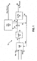
- system 10 includes CO 2 VPSA unit 30 positioned upstream of H 2 PSA unit 28.
- natural gas 12 and steam 14 can be reformed in steam methane reformer 16 to produce stream 18, as outlined in equation (1) hereinabove.
- Stream 18 is then fed to shift reactor 20 to produce stream 22 as outlined in equation (2), as also set forth above.
- Stream 22 can be fed to CO 2 VPSA unit 30 via stream 24.
- Valve 26 will therefore typically be in the closed position and is in the open position when the CO 2 VPSA unit is not being used.
- valve 26 may alternatively be in the partially open position depending on the desired process capacity (i.e., CO 2 recovery).
- CO 2 -rich stream 36 (e.g. ⁇ 90 mole%) can be produced, together with H 2 -rich feed 32 that is expected to result in higher H 2 recovery 38 from H 2 PSA unit 28, and H 2 -depleted stream 34 (fuel stream) for use in the plant.
- Hydrogen PSA unit 28 can also produce fuel stream 40 for use in plant 10.
- the present invention recognizes that depressurizations of a CO 2 -selective adsorbent layer increases the CO 2 concentration in the adsorbent bed(s). More specifically, the present invention recognizes and utilizes depressurizations of an adsorbent from high pressure (e.g., 689,5 to 3447,4 kPa (100-500 psia)) to low pressure(s) (i.e., close to ambient and/or subambient pressures) to increase CO 2 concentration in the bed.
- high pressure e.g., 689,5 to 3447,4 kPa (100-500 psia)
- low pressure(s) i.e., close to ambient and/or subambient pressures
- a "feed stream" being fed to a CO 2 VPSA unit in accordance with the present invention is a stream containing at least H 2 and CO 2 at a pressure between about 689,5 to 3447,4 kPa (100-500 psia) (e.g., 2585,5 kPa (375 psia)).
- the CO 2 concentration is increased by multiple depressurizations, it can be used to produce the CO 2 product by further pressure reduction.
- depressurization from high to low pressure increases CO 2 concentration in the adsorbent bed. This step in the process can be used to eliminate several process steps as described in the prior art.
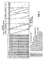
- the CO 2 VPSA unit includes five beds and utilizes nine steps. At any given time during the process, the beds will be in one of the following categories of steps: feed, depressurizations, evacuation, pressure equalizations and repressurization.
- feed depressurizations
- evacuation evacuation
- pressure equalizations pressure equalizations
- repressurization repressurization
- the CO 2 VPSA unit includes six beds and utilizes eleven steps. At any given time during the process, the beds will be in one of the following categories of steps: feed, depressurizations, evacuation, pressure equalizations and repressurization.
- each bed is preferably packed with at least two layers of adsorbents.
- the type and sizing of the adsorbent layer toward the feed end (i.e., a water-selective adsorbent layer) in the bed is selected to remove moisture in the feed stream such that any residual moisture does not deteriorate the performance of the main (i.e., CO 2 -selective) adsorbent layer.
- the water-selective adsorbent layer is also preferably capable of removing impurities (e.g., trace amounts of sulfur or heavy hydrocarbon compounds) from the feed stream, to the extent such impurities are present.
- the main, second adsorbent layer i.e., the CO 2 -selective adsorbent layer
- the main, second adsorbent layer is used for selectively adsorbing CO 2 from the feed stream after sufficient moisture has been removed.
- adsorbents such as activated alumina, silica gel or zeolite molecular sieve are preferred.
- adsorbents are intended to be illustrative and other adsorbents capable of removing sufficient moisture are also suitable for use in accordance with the present invention.
- Preferred characteristics for such adsorbent(s) include: high crush strength capabilities, high attrition resistance, large bulk density, low inter-particle void, high heat capacity, large thermal conductivity, low-pressure drop and stable in liquid water.
- the main adsorbent layer (i.e., the CO 2 -selective adsorbent layer) following the water-selective adsorbent layer preferably has the following characteristics: high selectivity, high working capacity, fast kinetics and low heat of adsorption.
- Typical examples of such adsorbents include, but are not limited to: NaY, HY, NaX, silica gel, and activated carbon.
- Other desired physical properties of the main layer adsorbents (i.e. the CO 2 -selective layer) include high crush strength, high attrition resistance, large bulk density, low inter-particle void, high heat capacity, large thermal conductivity and low-pressure drop during the feed and evacuation steps.
- FIG. 2-4 a CO 2 VPSA unit having five beds (A1-A5) and utilizing nine process steps are shown. This embodiment of the invention employs two pressure equalizations, as shown. These process steps include:
- the nine-step process described is for one cycle for one bed in the CO 2 VPSA unit.
- the nine steps in this embodiment are carried out in a cyclic manner with the other beds in the CO 2 VPSA unit such that the feed-in and feed-effluent from step 1 are continuous.
- the evacuation step is continuous. This ensures that the vacuum pump operates continuously and that there is no interruption in feed into the CO 2 VPSA or to the H 2 PSA units.
- FIG. 5 An alternative to a two train, five-bed arrangement for such flows is shown in Figure 5 .
- the variation shown in Figure 5 is also a nine-step process having two pressure equalizations as described above. In this embodiment, however, one train of eight beds (A1-A8) is used.
- two beds are continuously in a feed step and at least two beds are continuously in an evacuation step.
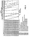
- FIG. 6-8 An alternative and preferred embodiment of the present invention is illustrated in Figures 6-8 .
- This embodiment allows for higher CO 2 recovery.
- the arrangement shown in Figures 6-8 utilizes one train of six beds in the CO 2 VPSA unit. In this embodiment, there are eleven process steps and three pressure equalizations.
- steps DP3 and PE3 are additional steps relative to the embodiment shown in Figures 2-4 .
- a process cycle for the embodiment shown in Figures 6-8 is as follows:
- the eleven-step process described is for one cycle for one bed in the CO 2 VPSA unit.
- the eleven steps in this embodiment are carried out in a cyclic manner with the other beds in the CO 2 VPSA unit such that the feed-in and feed-effluent from step 1 are continuous.
- the evacuation step is continuous. This ensures that the vacuum pump operates continuously and that there is no interruption in feed into the CO 2 VPSA or to the H 2 PSA units.
- the nine step process cycle of Figure 2 described above was tested on a single-bed bench scale unit and is expected to readily scale up for a five-bed system.
- the inner diameter (ID) of the column was 1,73 cm (0,68) inches and the packed bed height was 1,52 m (5 feet).
- the column was packed with about 0,227 kg (0,5 lb) of commercially available 1/16 inch NaY pellets.
- the feed contained 74 mole% helium (to simulate H 2 for safety reasons), 16 mole% CO 2 and 10 mole% CH 4 (to simulate CH 4 +CO + N 2 ).
- the feed was at about 2578,6 kPa (374 psia).
- the process was run in a cyclic manner until it reached cyclic steady state.
- the bed was depressurized to about 137,9 kPa (20 psia). This was followed by evacuation to about 27,6 kPa (4 psia). The quantity and concentration of the depressurized and evacuated gas was measured.
- P* pressure at the end of the fourth step (P*) to be about 275,8 kPa (40 psia)
- the total CO 2 produced from steps five and six was approximately 2,2 mmole/kg (1 mmole/lb) at about 93% CO 2 purity and about 75% recovery.
- the present invention can be modified to produce higher amounts of CO 2 .
- one may need or desire to process higher feed flow rates than may be handled by a single vacuum train or single vessel (due to fluidization or transportation limitations).
- the nine process steps may be arranged such that more than one bed is on feed all the time and/or more than one bed is under evacuation all the time. As discussed hereinabove, an example of such an arrangement is shown in Figure 5 for a process with two pressure equalizations.
- the processes described herein may be operated at feed pressures higher than 689,5 kPa (100 psia), and more preferably greater than 2068,4 kPA (300 psia) (for example, about 2585,5 kPa (375 psia)).
- Carbon dioxide in the feed gas is preferably higher than 10 mole%, and most preferably greater than 15 mole% (e.g., 15-25 mole%).
- Feed temperature may be between about 4,4 to 93,3 °C (40-200 °F), more preferably between about 15,6 to 65,6 °C (60-150 °F), and most preferably about 37,8 °C (100 °F).
- storage tanks may be added in place of some of the adsorbent beds in the process cycle to store some of the intermediate gas streams such as the depressurized gas.
- the purpose of these storage tanks is to maintain flow into and out of the CO 2 VPSA unit as continuous.
- the present invention thus provides vacuum pressure swing adsorption (VPSA) processes and apparatus to recover CO 2 having a purity of approximately ⁇ 90 mole% from streams containing at least CO 2 and H 2 (e.g., syngas).
- VPSA vacuum pressure swing adsorption
- there is constant feed constant product being produced and rotating machinery is preferably run continuously so as to eliminate unnecessary tank(s).
- there are reasons for limiting the number of adsorbent beds e.g., high cost of the adsorbent) storage tanks instead of the adsorbent vessels may be used as explained above. While every bed in a given process cycle goes through the same cycle, the number of beds is to be minimized taking these factors into consideration.
- the feed to the CO 2 VPSA unit can be at super ambient pressure, and the CO 2 product can be produced in two streams as described above.
- H 2 recovery is expected to increase by extracting the CO 2 , thereby increasing H 2 partial pressure in the H 2 PSA feed stream.
- the recovered CO 2 can be used as produced or further upgraded such as shown in commonly owned U.S. Patent 7,871,457 , filed on even date herewith and entitled "Carbon Dioxide Production Method" by Shah et al.
- the recovered CO 2 can then be used, sequestered or used in applications such as enhanced oil recovery (EOR).
- EOR enhanced oil recovery
- the present invention is not limited to embodiments where the CO 2 VPSA unit is placed downstream of an SMR/shift reactor and upstream of a H 2 PSA unit.
- the present invention can also be used, for example, with a partial oxidation reactor together with any feed stream as defined hereinabove.
- the pressure equalization steps could be eliminated. This may reduce H 2 and/or CO 2 recovery since more H 2 and/or CO 2 could be present in stream 34. In such cases, the number of beds may be reduced.
Landscapes
- Chemical & Material Sciences (AREA)
- Engineering & Computer Science (AREA)
- Organic Chemistry (AREA)
- Analytical Chemistry (AREA)
- General Chemical & Material Sciences (AREA)
- Oil, Petroleum & Natural Gas (AREA)
- Chemical Kinetics & Catalysis (AREA)
- Combustion & Propulsion (AREA)
- Inorganic Chemistry (AREA)
- Separation Of Gases By Adsorption (AREA)
- Carbon And Carbon Compounds (AREA)
- Hydrogen, Water And Hydrids (AREA)
Claims (12)
- Vakuumdruckwechseladsorptions-(VPSA)-Verfahren zur Gewinnung von CO2 aus einem Mehrkomponentengasgemisch, welches mindestens CO2 und H2 enthält, in einer VPSA-Einheit, die mindestens ein Adsorptionsmittelbett enthält, welches mindestens ein CO2-selektives Adsorptionsmittel enthält, wobei im Zuge des Verfahrens:das mindestens CO2 und H2 enthaltende Mehrkomponentengasgemisch zu dem mindestens einen Adsorptionsmittelbett bei einem ersten Druck innerhalb eines ersten Druckbereichs über eine vorbestimmte Zeitdauer zugeführt wird, um einen an H2 angereicherten Strom zu erzeugen;das mindestens eine Adsorptionsmittelbett in einem ersten Entspannungsschritt von dem ersten Druckbereich auf einen zweiten Druck innerhalb eines zweiten Druckbereichs in der gleichen Richtung wie der Zufuhrstrom oder in einer entgegengesetzten Richtung hierzu entspannt wird;das mindestens eine Adsorptionsmittelbett in einem zweiten Entspannungsschritt von dem zweiten Druckbereich auf einen dritten Druck innerhalb eines dritten Druckbereichs, der geringer als der zweite Druckbereich ist, und in einer gleichen Richtung wie der Zufuhrstrom oder in einer Richtung entgegengesetzt hierzu entspannt wird;das mindestens eine Adsorptionsmittelbett in einem dritten Entspannungsschritt von dem dritten Druckbereich auf einen vorbestimmten Druckbereich (P*) in einer gleichen Richtung wie der Zufuhrstrom oder in einer Richtung entgegengesetzt zum Zufuhrstrom entspannt wird, um einen an H2 verarmten Strom zu erzeugen;das mindestens eine Adsorptionsmittelbett in einem Abblasschritt (BD) von dem P*-Druckbereich auf einen Druck nahe Umgebungsdruck in einer gleichen Richtung wie der Zufuhrstrom oder in einer Richtung entgegengesetzt hierzu entspannt wird, um mindestens einen ersten Teil von CO2-Produkt zu erzeugen;das mindestens eine Adsorptionsmittelbett von dem Druck nahe dem Umgebungsdruck auf einen Druck unter Umgebungsdruck in einer Richtung entgegengesetzt zu dem Zufuhrstrom oder in einer gleichen Richtung evakuiert wird, um mindestens einen zweiten Teil von CO2-Produkt zu erzeugen;der Druck des mindestens einen Adsorptionsmittelbetts in einem ersten Druckausgleichsschritt in einer Richtung entgegengesetzt zu dem Zufuhrstrom oder in einer gleichen Richtung ausgeglichen wird;das mindestens eine Adsorptionsmittelbett in einem zweiten Druckausgleichsschritt in einer Richtung entgegengesetzt zu dem Zufuhrstrom oder in einer gleichen Richtung hierzu weiter ausgeglichen wird; unddas mindestens eine Adsorptionsmittelbett in einem Wiederaufdrückschritt (RP) auf den ersten Druckbereich wieder aufgedrückt wird; wobei der Prozess zyklisch wiederholt wird.
- Verfahren gemäß Anspruch 1, bei welchem das mindestens eine Adsorptionsmittelbett fünf Betten umfasst.
- Verfahren gemäß Anspruch 1, bei welchem das mindestens eine Adsorptionsmittelbett acht Betten umfasst.
- Verfahren gemäß Anspruch 1, bei welchem der Druckbereich für den Druck unterhalb Umgebungsdruck von 6,9 bis 82,7 kPa (1 - 12 psia) reicht.
- Verfahren gemäß Anspruch 1, bei welchem:das mindestens CO2 und H2 enthaltende Mehrkomponentengasgemisch dem mindestens einen Adsorptionsmittelbett bis zu einem ersten Druck innerhalb eines ersten Druckbereichs über eine vorbestimmte Zeitdauer zugeführt wird, um einen an H2 angereicherten Strom zu erzeugen;das mindestens eine Adsorptionsmittelbett in einem ersten Entspannungsschritt von dem ersten Druckbereich auf einen zweiten Druck innerhalb eines zweiten Druckbereichs in einer gleichen Richtung wie der Zufuhrstrom oder in einer entgegengesetzten Richtung hierzu entspannt wird;das mindestens eine Adsorptionsmittelbett in einem zweiten Entspannungsschritt von dem zweiten Druckbereich auf einen dritten Druck innerhalb eines dritten Druckbereichs, der geringer als der zweite Druckbereich ist, und in einer gleichen Richtung wie der Zufuhrstrom oder in einer Richtung entgegengesetzt hierzu entspannt wird;das mindestens eine Adsorptionsmittelbett in einem dritten Entspannungsschritt von dem dritten Druckbereich auf einen vierten Druck innerhalb eines vierten Druckbereichs, der geringer als der dritte Druckbereich ist, und in einer gleichen Richtung wie der Zufuhrstrom oder in einer Richtung entgegengesetzt hierzu entspannt wird:das mindestens eine Adsorptionsmittelbett in einem vierten Entspannungsschritt von dem vierten Druckbereich auf einen vorbestimmten Druckbereich (P*) in einer gleichen Richtung wie der Zufuhrstrom oder in einer Richtung entgegengesetzt zum Zufuhrstrom entspannt wird, um einen an H2 verarmten Strom zu erzeugen;das mindestens eine Adsorptionsmittelbett in einem Abblasschritt (BD) von dem P*-Druckbereich auf einen Druck nahe Umgebungsdruck in einer gleichen Richtung wie der Zufuhrstrom oder in einer Richtung entgegengesetzt hierzu entspannt wird, um mindestens einen ersten Teil von CO2-Produkt zu erzeugen;das mindestens eine Adsorptionsmittefbett von dem Druck nahe dem Umgebungsdruck auf einen Druck unter Umgebungsdruck in einer gleichen Richtung wie der Zufuhrstrom oder in einer Richtung entgegengesetzt hierzu evakuiert wird, um mindestens einen zweiten Teil von CO2-Produkt zu erzeugen;der Druck des mindestens einen Adsorptionsmittelbetts in einem ersten Druckausgleichsschritt in einer gleichen Richtung wie der Zufuhrstrom oder in einer Richtung entgegengesetzt hierzu ausgeglichen wird;das mindestens eine Adsorptionsmittelbett in einem zweiten Druckausgleichsschritt in einer gleichen Richtung wie der Zufuhrstrom oder in einer Richtung entgegengesetzt hierzu weiter ausgeglichen wird;das mindestens eine Adsorptionsmittelbett in einem dritten Druckausgleichsschritt in einer gleichen Richtung wie der Zufuhrstrom oder in einer Richtung entgegengesetzt hierzu weiter ausgeglichen wird; unddas mindestens eine Adsorptionsmittelbett in einem Wiederaufdrückschritt (RP) auf den ersten Druckbereich wieder aufgedrückt wird; wobei das Verfahren zyklisch wiederholt wird.
- Verfahren gemäß Anspruch 5, bei welchem das mindestens eine Adsorptionsmittelbett sechs Betten umfasst.
- Verfahren gemäß Anspruch 1 oder 5, bei welchem der erste Druckbereich von 689,5 bis 3447,4 kPa (100 - 500 psia) reicht.
- Verfahren gemäß Anspruch 1 oder 5, bei welchem der zweite Druckbereich von 551,6 bis 2757,9 kPa (80 - 400 psia) reicht.
- Verfahren gemäß Anspruch 1 oder 5, bei welchem der dritte Druckbereich von 413,7 bis 2068,4 kPa (60 - 300 psia) reicht.
- Verfahren gemäß Anspruch 5, bei welchem der vierte Druckbereich von 344,7 bis 1378,9 kPa (50 - 200 psia) reicht.
- Verfahren gemäß Anspruch 5, bei welchem der Druckbereich für den Druck bei oder unter Umgebungsdruck von 6,9 bis 82,7 kPa (1 - 12 psia) reicht.
- Verfahren gemäß Anspruch 1 oder 5, bei welchem der an H2 angereichte Strom einer H2-Druckwechseladsorptions-(PSA)-Einheit zugeführt wird.
Applications Claiming Priority (2)
| Application Number | Priority Date | Filing Date | Title |
|---|---|---|---|
| US11/395,138 US7550030B2 (en) | 2006-04-03 | 2006-04-03 | Process and apparatus to recover high purity carbon dioxide |
| PCT/US2007/007756 WO2007126944A1 (en) | 2006-04-03 | 2007-03-28 | Vacuum pressure swing process to recover high purity carbon dioxide |
Publications (2)
| Publication Number | Publication Date |
|---|---|
| EP2007503A1 EP2007503A1 (de) | 2008-12-31 |
| EP2007503B1 true EP2007503B1 (de) | 2015-03-04 |
Family
ID=38283324
Family Applications (1)
| Application Number | Title | Priority Date | Filing Date |
|---|---|---|---|
| EP07754299.1A Not-in-force EP2007503B1 (de) | 2006-04-03 | 2007-03-28 | Vakuum/druckwechseladsorptionsverfahren zur wiedergewinnung von hochreinem kohlendioxid |
Country Status (9)
| Country | Link |
|---|---|
| US (1) | US7550030B2 (de) |
| EP (1) | EP2007503B1 (de) |
| KR (1) | KR20090006156A (de) |
| CN (1) | CN101460232B (de) |
| BR (1) | BRPI0709806A2 (de) |
| CA (1) | CA2647913A1 (de) |
| ES (1) | ES2534467T3 (de) |
| MX (1) | MX2008012827A (de) |
| WO (1) | WO2007126944A1 (de) |
Families Citing this family (22)
| Publication number | Priority date | Publication date | Assignee | Title |
|---|---|---|---|---|
| US7618478B2 (en) * | 2006-04-03 | 2009-11-17 | Praxair Technology, Inc. | Process and apparatus to recover medium purity carbon dioxide |
| US7763100B2 (en) * | 2006-07-06 | 2010-07-27 | Praxair Technology, Inc. | Vacuum pressure swing adsorption process and enhanced oxygen recovery |
| US7740688B2 (en) * | 2006-09-26 | 2010-06-22 | Praxair Technology, Inc. | Process and apparatus for carbon dioxide recovery |
| US7819932B2 (en) * | 2008-04-10 | 2010-10-26 | Carbon Blue-Energy, LLC | Method and system for generating hydrogen-enriched fuel gas for emissions reduction and carbon dioxide for sequestration |
| US8535417B2 (en) * | 2008-07-29 | 2013-09-17 | Praxair Technology, Inc. | Recovery of carbon dioxide from flue gas |
| US7927573B2 (en) * | 2008-09-26 | 2011-04-19 | Praxair Technology, Inc. | Multi-stage process for purifying carbon dioxide and producing acid |
| US8303930B2 (en) * | 2009-05-18 | 2012-11-06 | American Air Liquide, Inc. | Processes for the recovery of high purity hydrogen and high purity carbon dioxide |
| WO2011049858A2 (en) * | 2009-10-19 | 2011-04-28 | Greatpoint Energy, Inc. | Integrated enhanced oil recovery process |
| CN101862574B (zh) * | 2010-06-21 | 2012-10-24 | 北京北大先锋科技有限公司 | 一种真空变压吸附系统 |
| US8752390B2 (en) | 2010-07-13 | 2014-06-17 | Air Products And Chemicals, Inc. | Method and apparatus for producing power and hydrogen |
| US20120279391A1 (en) * | 2011-05-03 | 2012-11-08 | Ravi Kumar | Adsorption process to recover carbon dioxide from flue gas |
| US8709136B2 (en) | 2012-04-03 | 2014-04-29 | Air Products And Chemicals, Inc. | Adsorption process |
| EP2823872A3 (de) | 2014-09-11 | 2015-05-06 | Air Products And Chemicals, Inc. | Druckwechsel-Adsorptionsverfahren |
| US9381460B2 (en) | 2014-09-11 | 2016-07-05 | Air Products And Chemicals, Inc. | Pressure swing adsorption process |
| FR3069787B1 (fr) * | 2017-08-03 | 2019-08-09 | L'air Liquide, Societe Anonyme Pour L'etude Et L'exploitation Des Procedes Georges Claude | Procede de production continue d'un flux gazeux d'hydrogene |
| EP3806982A1 (de) * | 2018-06-14 | 2021-04-21 | SYSADVANCE - Sistemas de Engenharia S.A. | Mehrstufiges psa-verfahren zur entfernung von schadgasen aus rohmethanströmen |
| US10780387B1 (en) * | 2020-06-05 | 2020-09-22 | ARC Technologies Corp. | System and method for gas quality and efficiency of a pressure swing adsorption gas separation unit |
| US11505462B2 (en) * | 2021-02-15 | 2022-11-22 | Fluor Technologies Corporation | Pre-combustion CO2 removal in a natural gas fed steam methane reformer (SMR) based hydrogen plant |
| KR102623382B1 (ko) | 2021-06-30 | 2024-01-09 | 김창규 | 화장품 충진용 길이조절 노즐 |
| KR102631336B1 (ko) | 2021-08-27 | 2024-02-01 | 한국에너지기술연구원 | 수소 및 이산화탄소의 분리회수 시스템 |
| US12179143B2 (en) * | 2022-01-21 | 2024-12-31 | Air Products And Chemicals, Inc. | Flue gas decarbonization |
| KR102936126B1 (ko) | 2023-06-26 | 2026-03-09 | 주식회사 이앤켐솔루션 | 이산화탄소 흡착제 및 이를 이용한 이산화탄소 회수장치 |
Family Cites Families (19)
| Publication number | Priority date | Publication date | Assignee | Title |
|---|---|---|---|---|
| US486989A (en) * | 1892-11-29 | stoelting | ||
| DE2604305A1 (de) | 1976-02-04 | 1977-08-11 | Linde Ag | Verfahren zum zerlegen von gasgemischen |
| US4171206A (en) * | 1978-08-21 | 1979-10-16 | Air Products And Chemicals, Inc. | Separation of multicomponent gas mixtures |
| US4711645A (en) | 1986-02-10 | 1987-12-08 | Air Products And Chemicals, Inc. | Removal of water and carbon dioxide from atmospheric air |
| US4770676A (en) | 1986-05-16 | 1988-09-13 | Air Products And Chemicals, Inc. | Recovery of methane from land fill gas |
| US5051115A (en) | 1986-05-21 | 1991-09-24 | Linde Aktiengesellschaft | Pressure swing adsorption process |
| US4869894A (en) | 1987-04-15 | 1989-09-26 | Air Products And Chemicals, Inc. | Hydrogen generation and recovery |
| US4813980A (en) | 1987-10-16 | 1989-03-21 | Air Products And Chemicals, Inc. | Recovery of nitrogen, hydrogen and carbon dioxide from hydrocarbon reformate |
| US4846851A (en) * | 1987-10-27 | 1989-07-11 | Air Products And Chemicals, Inc. | Purification of ammonia syngas |
| US4913709A (en) | 1989-02-17 | 1990-04-03 | Ravi Kumar | Adsorption process for recovering two high purity gas products from multicomponent gas mixtures |
| US4914218A (en) * | 1989-02-17 | 1990-04-03 | Ravi Kumar | Adsorptive process for separating multicomponent gas mixtures |
| US4915711A (en) | 1989-05-18 | 1990-04-10 | Air Products And Chemicals, Inc. | Adsorptive process for producing two gas streams from a gas mixture |
| US5792239A (en) * | 1994-10-21 | 1998-08-11 | Nitrotec Corporation | Separation of gases by pressure swing adsorption |
| CN1075394C (zh) * | 1997-05-29 | 2001-11-28 | 伍仁兴 | 脱除变换气中二氧化碳的变压吸附方法 |
| US6245127B1 (en) | 1999-05-27 | 2001-06-12 | Praxair Technology, Inc. | Pressure swing adsorption process and apparatus |
| US6340382B1 (en) * | 1999-08-13 | 2002-01-22 | Mohamed Safdar Allie Baksh | Pressure swing adsorption process for the production of hydrogen |
| CN1283344C (zh) | 2001-07-31 | 2006-11-08 | 成都天立化工科技有限公司 | 尿素生产中氢氮气高回收率两段变压吸附脱碳工艺方法 |
| CN100490939C (zh) * | 2001-07-31 | 2009-05-27 | 成都天立化工科技有限公司 | 采用变压吸附技术从变换气中脱除二氧化碳的方法 |
| US7871457B2 (en) | 2006-04-03 | 2011-01-18 | Praxair Technology, Inc. | Carbon dioxide production method |
-
2006
- 2006-04-03 US US11/395,138 patent/US7550030B2/en not_active Expired - Fee Related
-
2007
- 2007-03-28 WO PCT/US2007/007756 patent/WO2007126944A1/en not_active Ceased
- 2007-03-28 CN CN2007800205885A patent/CN101460232B/zh not_active Expired - Fee Related
- 2007-03-28 BR BRPI0709806-5A patent/BRPI0709806A2/pt not_active Application Discontinuation
- 2007-03-28 ES ES07754299.1T patent/ES2534467T3/es active Active
- 2007-03-28 KR KR1020087026814A patent/KR20090006156A/ko not_active Ceased
- 2007-03-28 EP EP07754299.1A patent/EP2007503B1/de not_active Not-in-force
- 2007-03-28 MX MX2008012827A patent/MX2008012827A/es active IP Right Grant
- 2007-03-28 CA CA002647913A patent/CA2647913A1/en not_active Abandoned
Also Published As
| Publication number | Publication date |
|---|---|
| EP2007503A1 (de) | 2008-12-31 |
| BRPI0709806A2 (pt) | 2011-07-26 |
| CA2647913A1 (en) | 2007-11-08 |
| CN101460232B (zh) | 2012-01-11 |
| MX2008012827A (es) | 2009-03-06 |
| US7550030B2 (en) | 2009-06-23 |
| WO2007126944A1 (en) | 2007-11-08 |
| ES2534467T3 (es) | 2015-04-23 |
| KR20090006156A (ko) | 2009-01-14 |
| CN101460232A (zh) | 2009-06-17 |
| US20070227352A1 (en) | 2007-10-04 |
Similar Documents
| Publication | Publication Date | Title |
|---|---|---|
| EP2007503B1 (de) | Vakuum/druckwechseladsorptionsverfahren zur wiedergewinnung von hochreinem kohlendioxid | |
| EP2066424B1 (de) | Verfahren zur rückgewinnung von kohlendioxyd | |
| EP2374522A1 (de) | Verfahren zur Wiedergewinnung von Kohlendioxid mittlerer Reinheit | |
| US7404846B2 (en) | Adsorbents for rapid cycle pressure swing adsorption processes | |
| EP2080735A1 (de) | Verfahren und vorrichtung zur abtrennung von wasserstoffgas | |
| WO2012096812A1 (en) | Six bed pressure swing adsorption process operating in normal and turndown modes | |
| AU2012257892A1 (en) | Low energy cyclic PSA process | |
| AU2021377152B2 (en) | A process and plant for producing ultrahigh-purity hydrogen from low-grade hydrogen gas | |
| WO2023064977A1 (en) | A process and plant of vacuum pressure swing adsorption for producing pure carbon dioxide from industrial off-gas containing co2 | |
| US20120279391A1 (en) | Adsorption process to recover carbon dioxide from flue gas | |
| WO2013191696A1 (en) | Adsorption process to recover carbon dioxide from flue gas | |
| SIRCAR | Pressure swing adsorption technology for hydrogen purification-A status review |
Legal Events
| Date | Code | Title | Description |
|---|---|---|---|
| PUAI | Public reference made under article 153(3) epc to a published international application that has entered the european phase |
Free format text: ORIGINAL CODE: 0009012 |
|
| 17P | Request for examination filed |
Effective date: 20081001 |
|
| AK | Designated contracting states |
Kind code of ref document: A1 Designated state(s): AT BE BG CH CY CZ DE DK EE ES FI FR GB GR HU IE IS IT LI LT LU LV MC MT NL PL PT RO SE SI SK TR |
|
| AX | Request for extension of the european patent |
Extension state: AL BA HR MK RS |
|
| DAX | Request for extension of the european patent (deleted) | ||
| RBV | Designated contracting states (corrected) |
Designated state(s): DE ES IT |
|
| 17Q | First examination report despatched |
Effective date: 20130221 |
|
| RIC1 | Information provided on ipc code assigned before grant |
Ipc: B01D 53/047 20060101AFI20140815BHEP Ipc: C01B 3/56 20060101ALI20140815BHEP |
|
| GRAP | Despatch of communication of intention to grant a patent |
Free format text: ORIGINAL CODE: EPIDOSNIGR1 |
|
| INTG | Intention to grant announced |
Effective date: 20141015 |
|
| GRAS | Grant fee paid |
Free format text: ORIGINAL CODE: EPIDOSNIGR3 |
|
| GRAA | (expected) grant |
Free format text: ORIGINAL CODE: 0009210 |
|
| AK | Designated contracting states |
Kind code of ref document: B1 Designated state(s): DE ES IT |
|
| REG | Reference to a national code |
Ref country code: DE Ref legal event code: R096 Ref document number: 602007040484 Country of ref document: DE Effective date: 20150423 Ref country code: ES Ref legal event code: FG2A Ref document number: 2534467 Country of ref document: ES Kind code of ref document: T3 Effective date: 20150423 |
|
| REG | Reference to a national code |
Ref country code: DE Ref legal event code: R097 Ref document number: 602007040484 Country of ref document: DE |
|
| PG25 | Lapsed in a contracting state [announced via postgrant information from national office to epo] |
Ref country code: IT Free format text: LAPSE BECAUSE OF NON-PAYMENT OF DUE FEES Effective date: 20150328 |
|
| PLBE | No opposition filed within time limit |
Free format text: ORIGINAL CODE: 0009261 |
|
| STAA | Information on the status of an ep patent application or granted ep patent |
Free format text: STATUS: NO OPPOSITION FILED WITHIN TIME LIMIT |
|
| 26N | No opposition filed |
Effective date: 20151207 |
|
| PGFP | Annual fee paid to national office [announced via postgrant information from national office to epo] |
Ref country code: ES Payment date: 20160328 Year of fee payment: 10 |
|
| PGFP | Annual fee paid to national office [announced via postgrant information from national office to epo] |
Ref country code: DE Payment date: 20160331 Year of fee payment: 10 |
|
| REG | Reference to a national code |
Ref country code: DE Ref legal event code: R119 Ref document number: 602007040484 Country of ref document: DE |
|
| PG25 | Lapsed in a contracting state [announced via postgrant information from national office to epo] |
Ref country code: DE Free format text: LAPSE BECAUSE OF NON-PAYMENT OF DUE FEES Effective date: 20171003 |
|
| REG | Reference to a national code |
Ref country code: ES Ref legal event code: FD2A Effective date: 20180706 |
|
| PG25 | Lapsed in a contracting state [announced via postgrant information from national office to epo] |
Ref country code: ES Free format text: LAPSE BECAUSE OF NON-PAYMENT OF DUE FEES Effective date: 20170329 |