EP2007294B1 - Dermabrasions-handstück - Google Patents
Dermabrasions-handstück Download PDFInfo
- Publication number
- EP2007294B1 EP2007294B1 EP07734232.7A EP07734232A EP2007294B1 EP 2007294 B1 EP2007294 B1 EP 2007294B1 EP 07734232 A EP07734232 A EP 07734232A EP 2007294 B1 EP2007294 B1 EP 2007294B1
- Authority
- EP
- European Patent Office
- Prior art keywords
- handpiece
- support
- head
- axis
- ball
- Prior art date
- Legal status (The legal status is an assumption and is not a legal conclusion. Google has not performed a legal analysis and makes no representation as to the accuracy of the status listed.)
- Not-in-force
Links
- 230000033001 locomotion Effects 0.000 claims description 10
- 230000003534 oscillatory effect Effects 0.000 claims description 4
- 239000003082 abrasive agent Substances 0.000 claims description 2
- HBMJWWWQQXIZIP-UHFFFAOYSA-N silicon carbide Chemical compound [Si+]#[C-] HBMJWWWQQXIZIP-UHFFFAOYSA-N 0.000 claims description 2
- 229910010271 silicon carbide Inorganic materials 0.000 claims description 2
- 210000003491 skin Anatomy 0.000 description 9
- 210000004907 gland Anatomy 0.000 description 4
- 230000010355 oscillation Effects 0.000 description 4
- 208000035874 Excoriation Diseases 0.000 description 3
- 238000011282 treatment Methods 0.000 description 2
- 238000010009 beating Methods 0.000 description 1
- 230000005540 biological transmission Effects 0.000 description 1
- 239000002537 cosmetic Substances 0.000 description 1
- 230000008878 coupling Effects 0.000 description 1
- 238000010168 coupling process Methods 0.000 description 1
- 238000005859 coupling reaction Methods 0.000 description 1
- 210000002615 epidermis Anatomy 0.000 description 1
- 239000000463 material Substances 0.000 description 1
- 230000008092 positive effect Effects 0.000 description 1
- 238000005096 rolling process Methods 0.000 description 1
Images


Classifications
-
- A—HUMAN NECESSITIES
- A61—MEDICAL OR VETERINARY SCIENCE; HYGIENE
- A61B—DIAGNOSIS; SURGERY; IDENTIFICATION
- A61B17/00—Surgical instruments, devices or methods, e.g. tourniquets
- A61B17/54—Chiropodists' instruments, e.g. pedicure
-
- A—HUMAN NECESSITIES
- A61—MEDICAL OR VETERINARY SCIENCE; HYGIENE
- A61B—DIAGNOSIS; SURGERY; IDENTIFICATION
- A61B17/00—Surgical instruments, devices or methods, e.g. tourniquets
- A61B17/32—Surgical cutting instruments
- A61B2017/320004—Surgical cutting instruments abrasive
-
- A—HUMAN NECESSITIES
- A61—MEDICAL OR VETERINARY SCIENCE; HYGIENE
- A61H—PHYSICAL THERAPY APPARATUS, e.g. DEVICES FOR LOCATING OR STIMULATING REFLEX POINTS IN THE BODY; ARTIFICIAL RESPIRATION; MASSAGE; BATHING DEVICES FOR SPECIAL THERAPEUTIC OR HYGIENIC PURPOSES OR SPECIFIC PARTS OF THE BODY
- A61H23/00—Percussion or vibration massage, e.g. using supersonic vibration; Suction-vibration massage; Massage with moving diaphragms
- A61H23/02—Percussion or vibration massage, e.g. using supersonic vibration; Suction-vibration massage; Massage with moving diaphragms with electric or magnetic drive
Definitions
- the present invention relates to a dermabrasion handpiece.
- the present invention relates to a handpiece adapted to perform micro-pulsed massages and to abrade the epidermis of a patient.
- the distal end is provided with a central hole surrounded by an abrasive element.
- the hole is connected to a vacuum source for aspirating a portion of skin and for putting such portion of skin into contact with the abrasive element. The operator, by manually displacing the handpiece on the patient's skin, abrades the same.
- a rotating blade is used to abrade the skin.
- handpieces only approximately solve the problem of performing a homogenous skin abrasion.
- some embodiments such as that which contemplate a rotating blade, are potentially dangerous.
- a dermabrasion device which is also capable of performing micro-massage actions on the patient's skin.
- a dermabrasion device is thus made according to the attached claims.
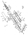
- numeral 10 generically indicates, as a whole, an innovative handpiece adapted to abrade a user's skin and adapted to further perform micro-pulsed massages.
- Handpiece 10 comprises a first half-shell 11 and a second half-shell 12, which, by means of four screws 13 (accommodated in corresponding seats 14) define a casing CT, which encloses therein a plurality of functional elements which will be described hereafter.
- handpiece 10 comprises on a first proximal end 10a a plastic spiral-like element 15 crossed by a flexible electrical wire 16 by means of which an electrical connection of handpiece 10 itself to a programmable dermabrasion machine (not shown) is obtained.
- One end of electrical wire 16 end with a cable gland element 17 (integral with element 15), in turn fixed to half-shells 11, 12, by means of a washer 18 which is located on the other side with respect to an abutment 19 integral with second half-shell 12.
- one portion 17a of cable gland element 17 rests on a surface 20 of second half-shell 12, while washer 18 is in contact with a surface 21, again of second half-shell 12. Washer 18 is screwed onto a threaded portion 17b of cable gland element 17, thus fixing cable gland element 17 to the two half-shells 11, 12.
- Electrical wire 16 supplies a direct-current, low-voltage electrical motor 22, accommodated in use between two half-shells 11, 12.
- Electrical motor 22 presents a shaft 23 which is inserted in use in a hole 24 obtained in a first support 25 ( figure 3 ).
- axis (a) of shaft 23 presents an eccentricity (e) with respect to a central axis (b) of handpiece 10.
- shaft 23 is fixed to first support 25 by means of two threaded dowels 26, each of which is inserted in a corresponding threaded through hole 27, 28, with axis (c) perpendicular to axes (a) and (b).
- the free ends of threaded dowels 27 are tightened about shaft 23 and make it integral with first support 25 ( figure 3 ).
- first support 25 has a seat 29 (essentially conical) adapted to accommodate a first portion of a ball 30.
- a second portion of ball 30 is contained in a seat 31 (also essentially conical) made in a second support 32 ( figure 4 ) which is located in use on the opposite side of first support 25 with respect to ball 30.
- first support 25, second support 32 and ball 30 creates a motion transmission joint GT having particular features, as better described below.
- a seat 33 obtained in second support 32 accommodates a first end 34a of a spring 34 crossed by an end 35a of a head-holding shaft 35 ( figure 6 ).
- end 35a of head-holding shaft 35 is further made to cross through a ball joint 36 ( figure 2 ).
- head-holding shaft 35 presents a shoulder 35b on which a second end 34b of spring 34 rests ( figures 2 , 6 ).
- seats 29 and 31 are identical, conical, and both with axis of symmetry (b).
- head-holding shaft 35 like spring 34, has axis (b).
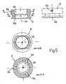
- ball joint 36 is accommodated in a supporting bush 37 ( figure 5 ). Furthermore, the external surface of ball joint 36 is locked onto support bearing 37 by the action of three dowels 38 arranged at 120° with respect to each other, each of which is fastened into a corresponding threaded seat 37a with axis (d) perpendicular to axis (b) ( figures 2 , 5 ).
- Spring 34 has a two-fold function.
- a certain beating, i.e. high-frequency vibration (micro-pulsation) of head-holding shaft 35 is allowed, and on the other hand ball 30 is maintained correctly in place between the two seats 29, 31, also in conditions of maximum effort or of creation of excessive clearance generated by the possible wear of seats 29, 31 due to the rolling action of ball 30 itself.
- head-holding shaft 35 presents two threaded portions 35c, 35d.
- a lock nut 39 ( figure 2 ) is screwed onto threaded portion 35c to "sandwich" ball joint 36 against an abutment 37b provided in support bush 37 ( figure 5 ).
- a head-holding support 40 which allows to accommodate abrasive heads T1, T2, T3, T4, T5 by pressure (in virtue of the presence of two O-rings 41, 42) is fastened onto the other end 35e (presenting treaded portion 35d) of head-holding shaft 35.
- head-holding support 40 presents an essentially cylindrical shape on whose outer surface two grooves 43, 44 are obtained, each of which is adapted to accommodate a corresponding 0-ring 41, 42.
- a blank threaded hole 45 (with axis (b)) is obtained in head-holding support 40 into which end 35e of head-holding shaft 35 is fastened in use.
- a cylindrical through hole 46 which allows the release of air from inside abrasive head T1, T2, T3, T4, T5 during its assembly on the head-holding support 40 extends parallelly to blank threaded hole 45.
- Each head T1, T2, T3, T4, T5 comprises three parts.
- each head T1, T2, T3, T4, T5 comprises a cylindrical support 47 which is hinged onto head-holding support 40 (and kept still by the 0-rings 41, 42), a slightly rounded ring 48 of abrasive material (for example, silicon carbide, of variable grain among five different FEPA grain size values from 280 to 1200), and a plastic material plate element 49, which inserted in the plastic cylindrical support 47 allows to keep ring 48 itself in position.
- abrasive material for example, silicon carbide, of variable grain among five different FEPA grain size values from 280 to 1200
- Handpiece 10 is completed by an electronic board SP (fixed to the first half-shell by means of two screws 43) and an operating button PL of electrical motor 22 and thus of heads T1, T2, T3, T4, T5 ( figures 1 , 2 ).
- shaft 23 of electrical motor 22 may be made to rotate at different speeds (e.g. at three different speeds) to implement different dermabrasion treatments.
- handpiece 10 object of the present invention is easily inferred from description above.
- the rotation of shaft 23 generates a similar rotation of first support 25. Motion is transmitted firstly to ball 30 and then to second support 32 to which shaft 35 is fixed. Since axis (a) of shaft 23 is offset by an eccentricity (e) with respect to axis (b) of the handpiece, an oscillation is generated on ball 30, oscillation which is transmitted to second support 32 and to shaft 35, which, being supported by ball joint 36, starts oscillating about axis (b).
- the oscillations are thus transmitted to head-holding support 40 and to head T1, T2, T3, T4, T5 which is in use in that moment.
- the movement of ring 48 is not only vibratory but also oscillatory with respect to a laying plane initially perpendicular to axis (b). In this manner, an oscillatory motion of ring 47 with respect to a plane perpendicular to axis (b) is generated, which is transposed into a series of pleasant micro-massages on the patient's skin in addition to the dermabrasion action due to the vibratory motion about axis (b).
- an operator (not shown), after having carefully chosen one of heads T1, T2, T3, T4, T5 (according to the type of treatment to be performed), selects a rotation speed of shaft 23 (and thus the vibration speed ring 47 on the skin to be treated), for example by means of a sector situated on the dermabrasion machine (not shown) to which handpiece 10 is electrically connected. The operator then displaces ring 47 over the entire body surface to be treated.
- the main advantage of above-described handpiece 10 object of the present invention consists in that by means of a simple mechanism comprising two supports 25, 32 and a ball 30 it is possible to transform the single rotational movement of shaft 23 of electrical motor 22 into vibrations and oscillations by means of which a pleasant massage is performed in addition to a dermabrasion on the patient's skin.
Landscapes
- Health & Medical Sciences (AREA)
- Life Sciences & Earth Sciences (AREA)
- Surgery (AREA)
- Molecular Biology (AREA)
- Engineering & Computer Science (AREA)
- Biomedical Technology (AREA)
- Heart & Thoracic Surgery (AREA)
- Medical Informatics (AREA)
- Nuclear Medicine, Radiotherapy & Molecular Imaging (AREA)
- Animal Behavior & Ethology (AREA)
- General Health & Medical Sciences (AREA)
- Public Health (AREA)
- Veterinary Medicine (AREA)
- Massaging Devices (AREA)
- Dental Tools And Instruments Or Auxiliary Dental Instruments (AREA)
- Walking Sticks, Umbrellas, And Fans (AREA)
Claims (9)
- Kombiniertes Dermabrasions- und Hautmassage-Handstück (10); wobei das Handstück (10) Betätigungsmittel (22, 23), einen Kopf (T1, T2, T3, T4, T5), der mit zumindest einem abrasiven Element (47) versehen ist, und ein Gelenk (GT) umfasst, das angepasst ist, eine erste Schwingbewegung um eine erste Achse (b) auf den Kopf (T1, T2, T3, T4, T5) aufzubringen;
wobei das Gelenk (GT) ferner auf das abrasive Element (47) eine zweite Schwingbewegung um eine Ebene senkrecht zu der ersten Achse (b) aufbringt, um Hautmikromassagen zu erzielen;
wobei das Handstück (10) dadurch gekennzeichnet ist, dass das Gelenk (GT) eine Kugel (30) umfasst, die zwischen einem ersten Träger (25) und einem zweiten Träger (32) befestigt ist, wobei der erste Träger (25) von einem Element (23) gedreht wird, das eine zweite Achse (a) versetzt um eine Exzentrizität (e) bezüglich der ersten Achse (b) darstellt, wobei die Exzentrizität (e) angepasst ist, eine Orbitalbewegung bzw. kreisförmige Bewegung des Kopfs (T1, T2, T3, T4, T5) auf der Haut zu erzeugen. - Handstück (10) nach Anspruch 1, dadurch gekennzeichnet, dass die Kugel (30) teilweise in einem ersten Sitz (29), der in dem ersten Träger (25) gemacht ist, und teilweise in einem zweiten Sitz (31) enthalten ist, der in dem zweiten Träger (32) gemacht ist, der bei Gebrauch auf der gegenüberliegenden bzw. entgegengesetzten Seite des ersten Trägers (25) bezüglich der Kugel (30) ausgerichtet ist.
- Handstück (10) nach Anspruch 2, dadurch gekennzeichnet, dass die Sitze (29, 31) im Wesentlichen konisch sind.
- Handstück (10) nach Anspruch 2 oder 3, dadurch gekennzeichnet, dass die Träger (25, 32) durch elastische Mittel (34) gegeneinander gedrückt werden.
- Handstück (10) nach einem der vorhergehenden Ansprüche, dadurch gekennzeichnet, dass der zweite Träger (32) einen Sitz (33) vorsieht, der angepasst ist, ein Ende (35a) eines Schafts (35) aufzunehmen.
- Handstück (10) nach Anspruch 5, dadurch gekennzeichnet, dass der Schaft (35) von einem Kugelgelenk (36) getragen ist.
- Handstück (10) nach Anspruch 6, dadurch gekennzeichnet, dass der Schaft (35) Mittel (35d) zum Befestigen eines Kopfhalteträgers (40) umfasst, der angepasst ist, einen der Köpfe (T1, T2, T3, T4, T5) zu tragen.
- Handstück (10) nach Anspruch 7, dadurch gekennzeichnet, dass der Kopfhalteträger (40) zumindest zwei O-Ringe (41, 42) zum schnellen Fixieren und Lösen eines der Köpfe (T1, T2, T3, T4, T5) aufweist.
- Handstück (10) nach einem der vorhergehenden Ansprüche, dadurch gekennzeichnet, dass das abrasive Material, aus dem das abrasive Element (47) besteht, Siliziumkarbid umfasst, und zwar aus variablem Korn bzw. variabler Korngröße aus fünf unterschiedlichen FEPA-Korngrößenwerten von 280 bis 1200.
Applications Claiming Priority (2)
| Application Number | Priority Date | Filing Date | Title |
|---|---|---|---|
| IT000264A ITBO20060264A1 (it) | 2006-04-07 | 2006-04-07 | Manipolo per la dermoabrasione |
| PCT/IB2007/000913 WO2007116292A2 (en) | 2006-04-07 | 2007-04-06 | Dermabrasion handpiece |
Publications (2)
| Publication Number | Publication Date |
|---|---|
| EP2007294A2 EP2007294A2 (de) | 2008-12-31 |
| EP2007294B1 true EP2007294B1 (de) | 2017-03-22 |
Family
ID=38529641
Family Applications (1)
| Application Number | Title | Priority Date | Filing Date |
|---|---|---|---|
| EP07734232.7A Not-in-force EP2007294B1 (de) | 2006-04-07 | 2007-04-06 | Dermabrasions-handstück |
Country Status (4)
| Country | Link |
|---|---|
| US (1) | US20090222024A1 (de) |
| EP (1) | EP2007294B1 (de) |
| IT (1) | ITBO20060264A1 (de) |
| WO (1) | WO2007116292A2 (de) |
Families Citing this family (6)
| Publication number | Priority date | Publication date | Assignee | Title |
|---|---|---|---|---|
| JP5934097B2 (ja) * | 2009-09-30 | 2016-06-15 | キム コール | 布地手入れ用具 |
| US8858570B2 (en) * | 2012-07-19 | 2014-10-14 | Henry Ping Chang | Skin treatment apparatus |
| US11819296B1 (en) * | 2013-03-15 | 2023-11-21 | Alan Silver | Advanced system and method for a deep tissue massager |
| US10034813B1 (en) * | 2013-03-15 | 2018-07-31 | Alan H. Silver | System and method for a deep tissue massager |
| US9750533B2 (en) * | 2013-04-12 | 2017-09-05 | L'oreal | Exfoliating head for a personal care appliance |
| CN105125259B (zh) * | 2015-07-31 | 2018-06-01 | 苏州益诺斯医疗科技有限公司 | 医用刨刀动力系统 |
Family Cites Families (11)
| Publication number | Priority date | Publication date | Assignee | Title |
|---|---|---|---|---|
| US807299A (en) * | 1904-10-06 | 1905-12-12 | David T Marshall | Vibrator for medical use. |
| US795212A (en) * | 1905-02-20 | 1905-07-18 | George W Fitz | Massage apparatus. |
| US795213A (en) * | 1905-04-21 | 1905-07-18 | George W Fitz | Massage apparatus. |
| US855342A (en) * | 1906-10-04 | 1907-05-28 | Henry J Hunger | Movement-cure device. |
| US912016A (en) * | 1908-04-27 | 1909-02-09 | Willis I Miller | Massaging device. |
| US1717501A (en) * | 1924-12-17 | 1929-06-18 | Thomas H Fisher | Vibrator |
| US5690541A (en) * | 1995-10-10 | 1997-11-25 | General Electric Company | Methods and apparatus for polishing seal surfaces in a nuclear reactor |
| FR2765471B1 (fr) * | 1997-07-07 | 1999-10-15 | Podiafrance | Instrument a main destine a l'abrasion des couches de cornees plantaires et talonnieres |
| US6241739B1 (en) * | 1999-11-12 | 2001-06-05 | Altair Instruments, Inc. | Microdermabrasion device and method of treating the skin surface |
| US6312322B1 (en) * | 2000-05-24 | 2001-11-06 | Po-Fu Chang | Hand held grinder |
| US6629983B1 (en) * | 2000-10-27 | 2003-10-07 | Edge Systems Corporation | Apparatus and method for skin/surface abrasion |
-
2006
- 2006-04-07 IT IT000264A patent/ITBO20060264A1/it unknown
-
2007
- 2007-04-06 EP EP07734232.7A patent/EP2007294B1/de not_active Not-in-force
- 2007-04-06 US US12/296,170 patent/US20090222024A1/en not_active Abandoned
- 2007-04-06 WO PCT/IB2007/000913 patent/WO2007116292A2/en active Application Filing
Non-Patent Citations (1)
| Title |
|---|
| None * |
Also Published As
| Publication number | Publication date |
|---|---|
| US20090222024A1 (en) | 2009-09-03 |
| WO2007116292A8 (en) | 2008-11-13 |
| WO2007116292A3 (en) | 2008-01-31 |
| EP2007294A2 (de) | 2008-12-31 |
| ITBO20060264A1 (it) | 2007-10-08 |
| WO2007116292A2 (en) | 2007-10-18 |
Similar Documents
| Publication | Publication Date | Title |
|---|---|---|
| EP2007294B1 (de) | Dermabrasions-handstück | |
| EP0916331B1 (de) | Tragbare Massagevorrichtung | |
| US1763730A (en) | Surgical saw | |
| US20100083975A1 (en) | Rotary Nailcare Device with Mandrel Bit for Nail Shaping, Filing, and Polishing | |
| JP2000509637A (ja) | 超音波伝達部品の制動装置 | |
| US11529163B2 (en) | Surgical systems and tools for moving energy applicators in superimposed modes | |
| US20180289986A1 (en) | Treatment instrument, distal side probe unit, and proximal side probe unit | |
| US20220015988A1 (en) | Massage tool rotatably attachable to a reciprocating motor | |
| US11723673B2 (en) | Method and apparatus to select vibration | |
| JP2715155B2 (ja) | 歯科器具 | |
| US5318445A (en) | Process and instrument for dental treatment | |
| US4007735A (en) | Cervical dilation vibrator | |
| US11957361B2 (en) | Non-rotational bone cutting tools and related systems and methods | |
| JP2013039318A (ja) | フレキシブルマッサージ機 | |
| KR102260159B1 (ko) | 스케일러 고정 및 연마 장치 | |
| JP6852152B2 (ja) | 鋸歯車セット | |
| JP7453239B2 (ja) | 自在継手組立体 | |
| JP4125993B2 (ja) | エア駆動式歯科用ハンドピース及び出力調整用アダプター | |
| JP4056932B2 (ja) | 歯科用スケーラー | |
| JPH0773581B2 (ja) | 超音波治療器 | |
| JP2005176905A (ja) | 超音波処置装置 | |
| JP6618497B2 (ja) | ハンドピース型高周波振動式切削装置 | |
| WO2021181714A1 (ja) | 振動式除去装置 | |
| CN116269615A (zh) | 一种骨科机器人用角度可调磨钻 | |
| JP3264660B2 (ja) | ハンドスケーラー研磨装置 |
Legal Events
| Date | Code | Title | Description |
|---|---|---|---|
| PUAI | Public reference made under article 153(3) epc to a published international application that has entered the european phase |
Free format text: ORIGINAL CODE: 0009012 |
|
| 17P | Request for examination filed |
Effective date: 20081031 |
|
| AK | Designated contracting states |
Kind code of ref document: A2 Designated state(s): AT BE BG CH CY CZ DE DK EE ES FI FR GB GR HU IE IS IT LI LT LU LV MC MT NL PL PT RO SE SI SK TR |
|
| AX | Request for extension of the european patent |
Extension state: AL BA HR MK RS |
|
| RAP1 | Party data changed (applicant data changed or rights of an application transferred) |
Owner name: GP INVESTMENTI S.R.L. |
|
| DAX | Request for extension of the european patent (deleted) | ||
| 17Q | First examination report despatched |
Effective date: 20160616 |
|
| GRAP | Despatch of communication of intention to grant a patent |
Free format text: ORIGINAL CODE: EPIDOSNIGR1 |
|
| INTG | Intention to grant announced |
Effective date: 20161014 |
|
| GRAS | Grant fee paid |
Free format text: ORIGINAL CODE: EPIDOSNIGR3 |
|
| GRAA | (expected) grant |
Free format text: ORIGINAL CODE: 0009210 |
|
| AK | Designated contracting states |
Kind code of ref document: B1 Designated state(s): AT BE BG CH CY CZ DE DK EE ES FI FR GB GR HU IE IS IT LI LT LU LV MC MT NL PL PT RO SE SI SK TR |
|
| REG | Reference to a national code |
Ref country code: GB Ref legal event code: FG4D |
|
| REG | Reference to a national code |
Ref country code: CH Ref legal event code: EP |
|
| REG | Reference to a national code |
Ref country code: AT Ref legal event code: REF Ref document number: 876907 Country of ref document: AT Kind code of ref document: T Effective date: 20170415 |
|
| REG | Reference to a national code |
Ref country code: IE Ref legal event code: FG4D |
|
| REG | Reference to a national code |
Ref country code: DE Ref legal event code: R096 Ref document number: 602007050278 Country of ref document: DE |
|
| REG | Reference to a national code |
Ref country code: NL Ref legal event code: MP Effective date: 20170322 |
|
| PG25 | Lapsed in a contracting state [announced via postgrant information from national office to epo] |
Ref country code: GR Free format text: LAPSE BECAUSE OF FAILURE TO SUBMIT A TRANSLATION OF THE DESCRIPTION OR TO PAY THE FEE WITHIN THE PRESCRIBED TIME-LIMIT Effective date: 20170623 Ref country code: FI Free format text: LAPSE BECAUSE OF FAILURE TO SUBMIT A TRANSLATION OF THE DESCRIPTION OR TO PAY THE FEE WITHIN THE PRESCRIBED TIME-LIMIT Effective date: 20170322 Ref country code: LT Free format text: LAPSE BECAUSE OF FAILURE TO SUBMIT A TRANSLATION OF THE DESCRIPTION OR TO PAY THE FEE WITHIN THE PRESCRIBED TIME-LIMIT Effective date: 20170322 |
|
| REG | Reference to a national code |
Ref country code: LT Ref legal event code: MG4D |
|
| REG | Reference to a national code |
Ref country code: AT Ref legal event code: MK05 Ref document number: 876907 Country of ref document: AT Kind code of ref document: T Effective date: 20170322 |
|
| PG25 | Lapsed in a contracting state [announced via postgrant information from national office to epo] |
Ref country code: SE Free format text: LAPSE BECAUSE OF FAILURE TO SUBMIT A TRANSLATION OF THE DESCRIPTION OR TO PAY THE FEE WITHIN THE PRESCRIBED TIME-LIMIT Effective date: 20170322 Ref country code: LV Free format text: LAPSE BECAUSE OF FAILURE TO SUBMIT A TRANSLATION OF THE DESCRIPTION OR TO PAY THE FEE WITHIN THE PRESCRIBED TIME-LIMIT Effective date: 20170322 Ref country code: BG Free format text: LAPSE BECAUSE OF FAILURE TO SUBMIT A TRANSLATION OF THE DESCRIPTION OR TO PAY THE FEE WITHIN THE PRESCRIBED TIME-LIMIT Effective date: 20170622 |
|
| PGFP | Annual fee paid to national office [announced via postgrant information from national office to epo] |
Ref country code: IT Payment date: 20170531 Year of fee payment: 11 |
|
| PG25 | Lapsed in a contracting state [announced via postgrant information from national office to epo] |
Ref country code: NL Free format text: LAPSE BECAUSE OF FAILURE TO SUBMIT A TRANSLATION OF THE DESCRIPTION OR TO PAY THE FEE WITHIN THE PRESCRIBED TIME-LIMIT Effective date: 20170322 |
|
| PG25 | Lapsed in a contracting state [announced via postgrant information from national office to epo] |
Ref country code: ES Free format text: LAPSE BECAUSE OF FAILURE TO SUBMIT A TRANSLATION OF THE DESCRIPTION OR TO PAY THE FEE WITHIN THE PRESCRIBED TIME-LIMIT Effective date: 20170322 Ref country code: AT Free format text: LAPSE BECAUSE OF FAILURE TO SUBMIT A TRANSLATION OF THE DESCRIPTION OR TO PAY THE FEE WITHIN THE PRESCRIBED TIME-LIMIT Effective date: 20170322 Ref country code: RO Free format text: LAPSE BECAUSE OF FAILURE TO SUBMIT A TRANSLATION OF THE DESCRIPTION OR TO PAY THE FEE WITHIN THE PRESCRIBED TIME-LIMIT Effective date: 20170322 Ref country code: CZ Free format text: LAPSE BECAUSE OF FAILURE TO SUBMIT A TRANSLATION OF THE DESCRIPTION OR TO PAY THE FEE WITHIN THE PRESCRIBED TIME-LIMIT Effective date: 20170322 Ref country code: EE Free format text: LAPSE BECAUSE OF FAILURE TO SUBMIT A TRANSLATION OF THE DESCRIPTION OR TO PAY THE FEE WITHIN THE PRESCRIBED TIME-LIMIT Effective date: 20170322 Ref country code: SK Free format text: LAPSE BECAUSE OF FAILURE TO SUBMIT A TRANSLATION OF THE DESCRIPTION OR TO PAY THE FEE WITHIN THE PRESCRIBED TIME-LIMIT Effective date: 20170322 |
|
| REG | Reference to a national code |
Ref country code: DE Ref legal event code: R119 Ref document number: 602007050278 Country of ref document: DE |
|
| PG25 | Lapsed in a contracting state [announced via postgrant information from national office to epo] |
Ref country code: IS Free format text: LAPSE BECAUSE OF FAILURE TO SUBMIT A TRANSLATION OF THE DESCRIPTION OR TO PAY THE FEE WITHIN THE PRESCRIBED TIME-LIMIT Effective date: 20170722 Ref country code: PT Free format text: LAPSE BECAUSE OF FAILURE TO SUBMIT A TRANSLATION OF THE DESCRIPTION OR TO PAY THE FEE WITHIN THE PRESCRIBED TIME-LIMIT Effective date: 20170724 Ref country code: PL Free format text: LAPSE BECAUSE OF FAILURE TO SUBMIT A TRANSLATION OF THE DESCRIPTION OR TO PAY THE FEE WITHIN THE PRESCRIBED TIME-LIMIT Effective date: 20170322 |
|
| REG | Reference to a national code |
Ref country code: CH Ref legal event code: PL |
|
| REG | Reference to a national code |
Ref country code: IE Ref legal event code: MM4A |
|
| PLBE | No opposition filed within time limit |
Free format text: ORIGINAL CODE: 0009261 |
|
| REG | Reference to a national code |
Ref country code: FR Ref legal event code: ST Effective date: 20171229 |
|
| STAA | Information on the status of an ep patent application or granted ep patent |
Free format text: STATUS: NO OPPOSITION FILED WITHIN TIME LIMIT |
|
| PG25 | Lapsed in a contracting state [announced via postgrant information from national office to epo] |
Ref country code: FR Free format text: LAPSE BECAUSE OF NON-PAYMENT OF DUE FEES Effective date: 20170522 Ref country code: MC Free format text: LAPSE BECAUSE OF FAILURE TO SUBMIT A TRANSLATION OF THE DESCRIPTION OR TO PAY THE FEE WITHIN THE PRESCRIBED TIME-LIMIT Effective date: 20170322 Ref country code: DE Free format text: LAPSE BECAUSE OF NON-PAYMENT OF DUE FEES Effective date: 20171103 Ref country code: DK Free format text: LAPSE BECAUSE OF FAILURE TO SUBMIT A TRANSLATION OF THE DESCRIPTION OR TO PAY THE FEE WITHIN THE PRESCRIBED TIME-LIMIT Effective date: 20170322 |
|
| 26N | No opposition filed |
Effective date: 20180102 |
|
| PG25 | Lapsed in a contracting state [announced via postgrant information from national office to epo] |
Ref country code: LI Free format text: LAPSE BECAUSE OF NON-PAYMENT OF DUE FEES Effective date: 20170430 Ref country code: LU Free format text: LAPSE BECAUSE OF NON-PAYMENT OF DUE FEES Effective date: 20170406 Ref country code: CH Free format text: LAPSE BECAUSE OF NON-PAYMENT OF DUE FEES Effective date: 20170430 Ref country code: SI Free format text: LAPSE BECAUSE OF FAILURE TO SUBMIT A TRANSLATION OF THE DESCRIPTION OR TO PAY THE FEE WITHIN THE PRESCRIBED TIME-LIMIT Effective date: 20170322 |
|
| REG | Reference to a national code |
Ref country code: BE Ref legal event code: MM Effective date: 20170430 |
|
| PG25 | Lapsed in a contracting state [announced via postgrant information from national office to epo] |
Ref country code: IE Free format text: LAPSE BECAUSE OF NON-PAYMENT OF DUE FEES Effective date: 20170406 |
|
| PG25 | Lapsed in a contracting state [announced via postgrant information from national office to epo] |
Ref country code: BE Free format text: LAPSE BECAUSE OF NON-PAYMENT OF DUE FEES Effective date: 20170430 |
|
| PG25 | Lapsed in a contracting state [announced via postgrant information from national office to epo] |
Ref country code: MT Free format text: LAPSE BECAUSE OF NON-PAYMENT OF DUE FEES Effective date: 20170406 |
|
| PGFP | Annual fee paid to national office [announced via postgrant information from national office to epo] |
Ref country code: GB Payment date: 20180404 Year of fee payment: 12 |
|
| PG25 | Lapsed in a contracting state [announced via postgrant information from national office to epo] |
Ref country code: IT Free format text: LAPSE BECAUSE OF NON-PAYMENT OF DUE FEES Effective date: 20180406 |
|
| PG25 | Lapsed in a contracting state [announced via postgrant information from national office to epo] |
Ref country code: HU Free format text: LAPSE BECAUSE OF FAILURE TO SUBMIT A TRANSLATION OF THE DESCRIPTION OR TO PAY THE FEE WITHIN THE PRESCRIBED TIME-LIMIT; INVALID AB INITIO Effective date: 20070406 |
|
| PG25 | Lapsed in a contracting state [announced via postgrant information from national office to epo] |
Ref country code: CY Free format text: LAPSE BECAUSE OF NON-PAYMENT OF DUE FEES Effective date: 20170322 |
|
| GBPC | Gb: european patent ceased through non-payment of renewal fee |
Effective date: 20190406 |
|
| PG25 | Lapsed in a contracting state [announced via postgrant information from national office to epo] |
Ref country code: GB Free format text: LAPSE BECAUSE OF NON-PAYMENT OF DUE FEES Effective date: 20190406 |
|
| PG25 | Lapsed in a contracting state [announced via postgrant information from national office to epo] |
Ref country code: TR Free format text: LAPSE BECAUSE OF FAILURE TO SUBMIT A TRANSLATION OF THE DESCRIPTION OR TO PAY THE FEE WITHIN THE PRESCRIBED TIME-LIMIT Effective date: 20170322 |