EP2007191B1 - An unmanned autonomous vehicle for displacing feed - Google Patents
An unmanned autonomous vehicle for displacing feed Download PDFInfo
- Publication number
- EP2007191B1 EP2007191B1 EP07747265A EP07747265A EP2007191B1 EP 2007191 B1 EP2007191 B1 EP 2007191B1 EP 07747265 A EP07747265 A EP 07747265A EP 07747265 A EP07747265 A EP 07747265A EP 2007191 B1 EP2007191 B1 EP 2007191B1
- Authority
- EP
- European Patent Office
- Prior art keywords
- vehicle
- distance
- unmanned
- feed
- determining device
- Prior art date
- Legal status (The legal status is an assumption and is not a legal conclusion. Google has not performed a legal analysis and makes no representation as to the accuracy of the status listed.)
- Active
Links
Images

Classifications
-
- A—HUMAN NECESSITIES
- A01—AGRICULTURE; FORESTRY; ANIMAL HUSBANDRY; HUNTING; TRAPPING; FISHING
- A01K—ANIMAL HUSBANDRY; AVICULTURE; APICULTURE; PISCICULTURE; FISHING; REARING OR BREEDING ANIMALS, NOT OTHERWISE PROVIDED FOR; NEW BREEDS OF ANIMALS
- A01K5/00—Feeding devices for stock or game ; Feeding wagons; Feeding stacks
- A01K5/02—Automatic devices
- A01K5/0266—Automatic devices with stable trolleys, e.g. suspended
-
- A—HUMAN NECESSITIES
- A01—AGRICULTURE; FORESTRY; ANIMAL HUSBANDRY; HUNTING; TRAPPING; FISHING
- A01K—ANIMAL HUSBANDRY; AVICULTURE; APICULTURE; PISCICULTURE; FISHING; REARING OR BREEDING ANIMALS, NOT OTHERWISE PROVIDED FOR; NEW BREEDS OF ANIMALS
- A01K1/00—Housing animals; Equipment therefor
- A01K1/10—Feed racks
- A01K1/105—Movable feed barriers
Definitions
- the invention relates to an unmanned autonomous vehicle according to the preamble of claim 1.
- Unmanned vehicles are generally known. For example, an unmanned vehicle for cleaning a stable floor is described in EP-A-0 943 235 .
- Austrian Gebrauchsmuster AT-6016-U discloses a device that is movable along a guide means for displacing feed substantially transverse to the direction of travel.
- FR 2 862 489 discloses an unmanned autonomous vehicle for displacing feed lying on a floor substantially sidewardly.
- the unmanned vehicle uses a guiding cable to guide the vehicle along a desired trajectory.
- the invention aims at providing an unmanned vehicle that is capable, without guide means, of autonomously displacing feed substantially transverse to the direction of travel.
- this object is achieved by means of an unmanned autonomous vehicle for displacing feed lying on a floor substantially sidewardly, which vehicle is provided with two wheels that are separately drivable by separate drive means, a distance determining device for determining the distance from the vehicle to a wall portion, a torque difference adjusting device for adjusting the torque difference between the wheels, a control unit for controlling the vehicle and moving it in a direction of travel, and feed displacing means for displacing feed substantially sidewardly, the control unit being programmed in such a way that during operation the vehicle will maintain a distance determined by the distance determining device to the wall portion, which distance is greater than or equal to a pre-adjusted minimum distance to the wall portion, which minimum distance is adjustable during operation.
- this arrangement and the control unit programmed in this manner ensure that the unmanned autonomous vehicle, when displacing the feed at least substantially sidewardly, is correctly positioned and correctly propelled, despite an (unpredicted) reaction force being exerted on the unmanned vehicle by the feed.
- the adjustment of the preadjusted minimum distance may, for example, depend on the point of time of the day, the period of time elapsed since the unmanned vehicle was present at the same position, the sort of animals or the individual animals present at the wall portion, for example a feeding gate.
- the torque difference adjusting device is provided with a torque difference determining device for determining the torque difference between the wheels.
- the control unit is programmed in such a way that during operation the drivable wheels of the vehicle will show a torque difference determined by the torque difference determining device, which distance is smaller than or equal to a pre-adjusted maximum torque. Controlling the unmanned vehicle on the basis of the torque difference ensures that the unmanned vehicle will always displace an at least almost equal amount of feed substantially sidewardly, because the torque difference is precisely caused by and is proportional to the force that is needed for displacing an amount of feed.
- An in particular accurate sideward displacement of feed can be achieved if the unmanned vehicle is provided with an orientation determining device for determining the orientation of the centre line of the vehicle relative to the wall portion, the control unit being programmed in such a way that during operation the centre line of the vehicle will maintain an orientation determined by the orientation determining device relative to the wall portion, which orientation is at least almost equal to a pre-adjusted orientation.
- the control unit is programmed in such a way that for controlling the vehicle priority is given to the distance determined by the distance determining means in combination with the pre-adjusted minimum distance.
- the wall portion being a feeding gate where animals, such as cows for example, are present
- a too close approach to the animals might lead to un undesirably great unrest with the animals.
- a too small distance to the wall portion might lead to un undesirable accumulation of the feed.
- the pre-adjusted maximum torque difference and/or the pre-adjusted orientation are/is also adjustable during operation.
- the feed displacing means comprise a freely rotatable circular element whose outer circumference constitutes the outer circumference of the vehicle, no separate drive for the feed displacing means is needed, since the freely rotatable circular element is driven by the feed itself (substantially by friction engagement).
- the outer surface of the circular element may be provided with one or more friction increasing layers and/or elements.
- an embodiment of an unmanned vehicle according to the invention is characterized in that the circular element is tilted in such a way that, at least almost in the direction of travel of the vehicle, it is located closest to the floor. If the angle enclosed by the circular element and the floor is adjustable, the unmanned vehicle is capable of being adjusted so as to displace different sorts of feed in a correct manner at least almost substantially transverse to the direction of travel of the vehicle.
- the distance determining device preferably comprises an ultrasonic sensor. Furthermore, it is advantageous if the unmanned vehicle is provided with a device for detecting skid of at least one of the drivable wheels.
- the unmanned vehicle is provided with an open bottom, material, such as feed, is prevented from accumulating in the interior of the vehicle and possibly adversely affecting there the operation of the unmanned vehicle.
- feed can be supplied if the unmanned vehicle is provided with a storage container for containing feed, and with a discharge device for discharging feed to the floor.
- the storage container is preferably provided with a mixing device for mixing feed.
- the control unit controls the operation of the discharge device on the basis of data from the distance determining device and/or the torque difference determining device and/or the speed of the vehicle and/or the weight decrease of the storage container.
- the unmanned vehicle may be provided with a signalling device for supplying a signal (for example for drawing the attention of an owner and/or operator of the unmanned vehicle), the control unit controlling the operation of the signalling device on the basis of data from the distance determining device and/or the torque difference determining device.
- a signalling device for supplying a signal (for example for drawing the attention of an owner and/or operator of the unmanned vehicle)
- the control unit controlling the operation of the signalling device on the basis of data from the distance determining device and/or the torque difference determining device.
- Figures 1 and 2 show an unmanned autonomous vehicle 1 for displacing feed 3 lying on a floor substantially sidewardly to a feeding gate 2.
- the feed 3, that may be solid, liquid or a mixture thereof, has been deposited at the feeding gate 2 in a manner known per se, for example with the aid of a tractor.
- the present invention will also be applicable to other installations for supplying feed to animals, so that the feeding gate shown in Figure 2 is only one of the many examples of a wall portion in the vicinity of which feed can be deposited.
- wall portion all embodiments of partition elements are meant, either or not having an open structure, it being possible for the wall portion to assume many different, curved, rectilinear, angular, etc. shapes.
- the unmanned vehicle 1 comprises two wheels 4', 5' that are separately drivable by separate drive means 4, 5.
- the unmanned vehicle 1 is further provided with a distance determining device 6, in the embodiment shown an ultrasonic sensor, for determining the distance from the vehicle 1 to the feeding gate 2. It will be obvious that all sensors known in the technique, such as for example the sensors mentioned in the patent documents enumerated above, can be used for the purpose of distance determination.
- the unmanned vehicle 1 can be provided with an external, protective covering 7 provided with apertures 8, so that the ultrasonic sensor 6 is enabled to detect the feeding gate 2. In order to prevent material, such as feed and the like, from accumulating in the interior of the unmanned vehicle 1 via the apertures 8, the bottom of the unmanned vehicle 1 is at least partially open.
- the unmanned vehicle 1 further comprises an orientation determining device 9, in the embodiment shown a gyroscope, for determining the orientation of the centre line 14 of the vehicle 1 relative to the feeding gate 2.
- orientation determining device 9 in the embodiment shown a gyroscope, for determining the orientation of the centre line 14 of the vehicle 1 relative to the feeding gate 2.
- the unmanned vehicle 1 is also provided with a torque difference determining device 10 for determining the torque difference between the wheels 4', 5'.
- a torque difference determining device which uses data from the drive means 4, 5, is known per se.
- Such a torque-difference determining device can also be used for detecting skid of one of the wheels, after which detection it is possible to perform a correct action (reducing the number of revolutions per minute, alarming an operator).
- the unmanned vehicle 1 is further provided with a control unit 11 for controlling the unmanned vehicle 1 and moving it in a direction of travel, which control unit 11 is connected, via electric wires, or in a wireless manner if desired, with the distance determining device 6, the orientation determining device 9, the torque difference determining device 10, and the drives 4, 5 of the wheels 4', 5', for the purpose of exchanging data.
- the unmanned vehicle 1 For displacing feed 3 substantially transverse to the direction of travel V of the unmanned vehicle, the unmanned vehicle 1 is provided with feed displacing means 12.
- feed displacing means can be constituted by an obliquely disposed slide, or by a conveyor belt.
- these feed displacing means 12 are preferably constituted by a freely rotatable circular element 12, whose outer circumference constitutes the outer circumference of the unmanned vehicle 1.
- the circular element 12 which may be for example a ring or a disc, comes into contact with the feed, said element 12 is rotated automatically, in other words the circular element 12 is feed driven.
- the circular element 12 is tilted through an angle ⁇ in such a way that, at least almost in the direction of travel V of the vehicle 1, it is located closest to the floor.
- the angle ⁇ enclosed by the circular element 12 and the floor can be adjustable. If desired, the angle ⁇ is adjustable, during operation of the vehicle 1, by tilting means known per se (not shown in the drawing), such as a cylinder, that are controlled by the control unit 11.
- the control unit 11 is programmed in such a way that during operation the vehicle 1 will maintain a distance determined by the distance determining device 6 to the feeding gate 2, which distance is greater than or equal to a pre-adjusted minimum distance to the feeding gate, and that during operation the centre line 14 of the vehicle will maintain an orientation determined by the orientation determining device 9 relative to the feeding gate 2, which orientation is at least almost equal to a pre-adjusted orientation, and that during operation the drivable wheels 4', 5' of the unmanned vehicle 1 will show a torque difference determined by the torque difference determining device 10, which torque difference is smaller than or equal to a pre-adjusted maximum torque.
- the unmanned vehicle 1 will always maintain a correct orientation relative to the feeding gate 2, that the unmanned vehicle 1 will not come within the minimum distance to the feeding gate 2, and that it is ensured that the feed will not accumulate too much, because, in case of the unmanned vehicle 1 moving through a too large amount of feed, the torque difference would become too great.
- the control unit 11 is programmed in such a way that, for controlling the unmanned vehicle 1, priority is given to the distance determined by the distance determining means 6 in combination with the pre-adjusted minimum distance.
- the pre-adjustable distance is adjustable during operation.
- the adjustment may, for example, depend on the point of time of the day, the period of time elapsed since the unmanned vehicle was present at the same position, the sort of animals or the individual animals present at the feeding gate.
- the pre-adjusted maximum torque difference and/or the pre-adjusted orientation are/is adjustable during operation.
- the unmanned autonomous vehicle 1 is provided with a (non-shown) energy supply that is chargeable via sidewardly disposed charging strips 13 that are capable of being brought into contact with a charging device.
- a (non-shown) energy supply that is chargeable via sidewardly disposed charging strips 13 that are capable of being brought into contact with a charging device.
- Other ways of charging the energy supply, such as inductive means, are mentioned inter alia in the above-mentioned patent documents.
- the unmanned vehicle 1 may additionally be adapted to supply feed.
- the unmanned vehicle 1 may be provided with a storage container for containing feed, and with a discharge device for discharging feed to the floor.
- the storage container is preferably provided with a mixing device for mixing feed.
- the control unit controls the operation of the discharge device on the basis of data from the distance determining device and/or the torque difference determining device and/or the speed of the vehicle and/or the weight decrease of the storage container. This enables inter alia the supply of a uniform amount of feed.
- the unmanned vehicle 1 may be provided with a signalling device (for example a transmitting aerial with a suitable controlling transmission circuit) for supplying a signal (for example for drawing the attention of an owner and/or operator of the unmanned vehicle), the control unit controlling the operation of the signalling device on the basis of data from the distance determining device and/or the torque difference determining device.
- a signalling device for example a transmitting aerial with a suitable controlling transmission circuit
- the control unit controlling the operation of the signalling device on the basis of data from the distance determining device and/or the torque difference determining device.
Landscapes
- Life Sciences & Earth Sciences (AREA)
- Environmental Sciences (AREA)
- Animal Husbandry (AREA)
- Biodiversity & Conservation Biology (AREA)
- Birds (AREA)
- Zoology (AREA)
- Control Of Position, Course, Altitude, Or Attitude Of Moving Bodies (AREA)
- Feeding And Watering For Cattle Raising And Animal Husbandry (AREA)
- Platform Screen Doors And Railroad Systems (AREA)
Abstract
Description
- The invention relates to an unmanned autonomous vehicle according to the preamble of claim 1.
- Unmanned vehicles are generally known. For example, an unmanned vehicle for cleaning a stable floor is described in
EP-A-0 943 235 . - Furthermore, Austrian Gebrauchsmuster
AT-6016-U -
FR 2 862 489 - The invention aims at providing an unmanned vehicle that is capable, without guide means, of autonomously displacing feed substantially transverse to the direction of travel.
- According to the present invention, this object is achieved by means of an unmanned autonomous vehicle for displacing feed lying on a floor substantially sidewardly, which vehicle is provided with two wheels that are separately drivable by separate drive means, a distance determining device for determining the distance from the vehicle to a wall portion, a torque difference adjusting device for adjusting the torque difference between the wheels, a control unit for controlling the vehicle and moving it in a direction of travel, and feed displacing means for displacing feed substantially sidewardly, the control unit being programmed in such a way that during operation the vehicle will maintain a distance determined by the distance determining device to the wall portion, which distance is greater than or equal to a pre-adjusted minimum distance to the wall portion, which minimum distance is adjustable during operation. Precisely this arrangement and the control unit programmed in this manner ensure that the unmanned autonomous vehicle, when displacing the feed at least substantially sidewardly, is correctly positioned and correctly propelled, despite an (unpredicted) reaction force being exerted on the unmanned vehicle by the feed.
- The adjustment of the preadjusted minimum distance may, for example, depend on the point of time of the day, the period of time elapsed since the unmanned vehicle was present at the same position, the sort of animals or the individual animals present at the wall portion, for example a feeding gate.
- In an embodiment of an unmanned vehicle according to the invention, the torque difference adjusting device is provided with a torque difference determining device for determining the torque difference between the wheels. In this case, it is in particular preferred if the control unit is programmed in such a way that during operation the drivable wheels of the vehicle will show a torque difference determined by the torque difference determining device, which distance is smaller than or equal to a pre-adjusted maximum torque. Controlling the unmanned vehicle on the basis of the torque difference ensures that the unmanned vehicle will always displace an at least almost equal amount of feed substantially sidewardly, because the torque difference is precisely caused by and is proportional to the force that is needed for displacing an amount of feed.
- An in particular accurate sideward displacement of feed can be achieved if the unmanned vehicle is provided with an orientation determining device for determining the orientation of the centre line of the vehicle relative to the wall portion, the control unit being programmed in such a way that during operation the centre line of the vehicle will maintain an orientation determined by the orientation determining device relative to the wall portion, which orientation is at least almost equal to a pre-adjusted orientation.
- In an embodiment of un unmanned vehicle according to the present invention, the control unit is programmed in such a way that for controlling the vehicle priority is given to the distance determined by the distance determining means in combination with the pre-adjusted minimum distance. This prevents the unmanned vehicle from coming too close to the wall portion in the case of little feed lying on the floor. In particular in the case of the wall portion being a feeding gate where animals, such as cows for example, are present, a too close approach to the animals might lead to un undesirably great unrest with the animals. Moreover, a too small distance to the wall portion might lead to un undesirable accumulation of the feed.
- In a preferred embodiment of an unmanned vehicle according to the present invention, the pre-adjusted maximum torque difference and/or the pre-adjusted orientation are/is also adjustable during operation.
- If the feed displacing means comprise a freely rotatable circular element whose outer circumference constitutes the outer circumference of the vehicle, no separate drive for the feed displacing means is needed, since the freely rotatable circular element is driven by the feed itself (substantially by friction engagement). If desired, the outer surface of the circular element may be provided with one or more friction increasing layers and/or elements. For obtaining a reliable, substantially sideward displacement of the feed, an embodiment of an unmanned vehicle according to the invention is characterized in that the circular element is tilted in such a way that, at least almost in the direction of travel of the vehicle, it is located closest to the floor. If the angle enclosed by the circular element and the floor is adjustable, the unmanned vehicle is capable of being adjusted so as to displace different sorts of feed in a correct manner at least almost substantially transverse to the direction of travel of the vehicle.
- The distance determining device preferably comprises an ultrasonic sensor. Furthermore, it is advantageous if the unmanned vehicle is provided with a device for detecting skid of at least one of the drivable wheels.
- If the unmanned vehicle is provided with an open bottom, material, such as feed, is prevented from accumulating in the interior of the vehicle and possibly adversely affecting there the operation of the unmanned vehicle.
- According to an embodiment of an unmanned vehicle according to the invention, feed can be supplied if the unmanned vehicle is provided with a storage container for containing feed, and with a discharge device for discharging feed to the floor. The storage container is preferably provided with a mixing device for mixing feed. In this case it is advantageous if the control unit controls the operation of the discharge device on the basis of data from the distance determining device and/or the torque difference determining device and/or the speed of the vehicle and/or the weight decrease of the storage container. Alternatively or additionally, the unmanned vehicle may be provided with a signalling device for supplying a signal (for example for drawing the attention of an owner and/or operator of the unmanned vehicle), the control unit controlling the operation of the signalling device on the basis of data from the distance determining device and/or the torque difference determining device.
- The invention will now be explained in further detail with preference to the drawing, in which:
-
Figure 1 is a schematic side view of the unmanned vehicle according to the invention, and -
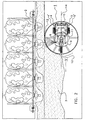
Figure 2 is a schematic plan view of the unmanned vehicle according to the invention to be used for displacing feed to a feeding gate. -
Figures 1 and2 show an unmanned autonomous vehicle 1 for displacingfeed 3 lying on a floor substantially sidewardly to a feeding gate 2. Thefeed 3, that may be solid, liquid or a mixture thereof, has been deposited at the feeding gate 2 in a manner known per se, for example with the aid of a tractor. It will be obvious that the present invention will also be applicable to other installations for supplying feed to animals, so that the feeding gate shown inFigure 2 is only one of the many examples of a wall portion in the vicinity of which feed can be deposited. In the present invention, by the term "wall portion" all embodiments of partition elements are meant, either or not having an open structure, it being possible for the wall portion to assume many different, curved, rectilinear, angular, etc. shapes. - Autonomously movable vehicles for performing many different functions, as well as the control of such vehicles, are known per se and will therefore not be described here in detail. Automatic charging of the energy supply of the vehicle and automatic loading and unloading of other materials into and from, respectively, containers present on the vehicle, are known as well. It will suffice to refer to the following patent documents:
US-2966256 ,DE-1109441 ,DE-1183301 ,EP-0382693 ,DE-4425924 ,US-5309592 ,EP-0142594 ,DE-4444508 ,GB-2313190 US-5109566 ,GB-2313191 US-3273038 ,NL-7416427 US-5341540 ,US-5646494 ,EP-0943235 ,EP-1369010 ,EP-1369012 enEP-1369017 . - The unmanned vehicle 1 comprises two wheels 4', 5' that are separately drivable by separate drive means 4, 5. The unmanned vehicle 1 is further provided with a
distance determining device 6, in the embodiment shown an ultrasonic sensor, for determining the distance from the vehicle 1 to the feeding gate 2. It will be obvious that all sensors known in the technique, such as for example the sensors mentioned in the patent documents enumerated above, can be used for the purpose of distance determination. The unmanned vehicle 1 can be provided with an external, protective covering 7 provided withapertures 8, so that theultrasonic sensor 6 is enabled to detect the feeding gate 2. In order to prevent material, such as feed and the like, from accumulating in the interior of the unmanned vehicle 1 via theapertures 8, the bottom of the unmanned vehicle 1 is at least partially open. - The unmanned vehicle 1 further comprises an
orientation determining device 9, in the embodiment shown a gyroscope, for determining the orientation of thecentre line 14 of the vehicle 1 relative to the feeding gate 2. It will be obvious that all sensors known in the technique, such as for example the sensors mentioned in the patent documents enumerated above, can be used for the purpose of orientation determination, such as an electronic compass or a camera with image recognition equipment. - The unmanned vehicle 1 is also provided with a torque
difference determining device 10 for determining the torque difference between the wheels 4', 5'. Such a torque difference determining device, which uses data from the drive means 4, 5, is known per se. Such a torque-difference determining device can also be used for detecting skid of one of the wheels, after which detection it is possible to perform a correct action (reducing the number of revolutions per minute, alarming an operator). - The unmanned vehicle 1 is further provided with a
control unit 11 for controlling the unmanned vehicle 1 and moving it in a direction of travel, whichcontrol unit 11 is connected, via electric wires, or in a wireless manner if desired, with thedistance determining device 6, theorientation determining device 9, the torquedifference determining device 10, and thedrives 4, 5 of the wheels 4', 5', for the purpose of exchanging data. - For displacing
feed 3 substantially transverse to the direction of travel V of the unmanned vehicle, the unmanned vehicle 1 is provided with feed displacing means 12. Such feed displacing means can be constituted by an obliquely disposed slide, or by a conveyor belt. However, according to an embodiment of the invention, these feed displacing means 12 are preferably constituted by a freely rotatablecircular element 12, whose outer circumference constitutes the outer circumference of the unmanned vehicle 1. When, during operation of the unmanned vehicle 1, thecircular element 12, which may be for example a ring or a disc, comes into contact with the feed, saidelement 12 is rotated automatically, in other words thecircular element 12 is feed driven. An extremely reproducible displacement of the feed is obtained if thecircular element 12 is tilted through an angle α in such a way that, at least almost in the direction of travel V of the vehicle 1, it is located closest to the floor. In dependence on the feed to be displaced, the angle α enclosed by thecircular element 12 and the floor, can be adjustable. If desired, the angle α is adjustable, during operation of the vehicle 1, by tilting means known per se (not shown in the drawing), such as a cylinder, that are controlled by thecontrol unit 11. - When the feed is deposited on the floor, and when the animals present at the feeding gate are eating the feed, the feed is accumulated over different distances to the feeding gate to different heights. In order that the animals are always able to reach in a simple manner a desired amount of feed it is ensured, by making the unmanned vehicle move regularly along the feeding gate 2, that feed is displaced to the feeding gate, as schematically shown in
Figure 2 . In order that the unmanned vehicle 1 is correctly controlled, thecontrol unit 11 is programmed in such a way that during operation the vehicle 1 will maintain a distance determined by thedistance determining device 6 to the feeding gate 2, which distance is greater than or equal to a pre-adjusted minimum distance to the feeding gate, and that during operation thecentre line 14 of the vehicle will maintain an orientation determined by theorientation determining device 9 relative to the feeding gate 2, which orientation is at least almost equal to a pre-adjusted orientation, and that during operation the drivable wheels 4', 5' of the unmanned vehicle 1 will show a torque difference determined by the torquedifference determining device 10, which torque difference is smaller than or equal to a pre-adjusted maximum torque. This means that the unmanned vehicle 1 will always maintain a correct orientation relative to the feeding gate 2, that the unmanned vehicle 1 will not come within the minimum distance to the feeding gate 2, and that it is ensured that the feed will not accumulate too much, because, in case of the unmanned vehicle 1 moving through a too large amount of feed, the torque difference would become too great. - The
control unit 11 is programmed in such a way that, for controlling the unmanned vehicle 1, priority is given to the distance determined by the distance determining means 6 in combination with the pre-adjusted minimum distance. - The pre-adjustable distance is adjustable during operation. The adjustment may, for example, depend on the point of time of the day, the period of time elapsed since the unmanned vehicle was present at the same position, the sort of animals or the individual animals present at the feeding gate. In a preferred embodiment of an unmanned vehicle, also the pre-adjusted maximum torque difference and/or the pre-adjusted orientation are/is adjustable during operation.
- The unmanned autonomous vehicle 1 is provided with a (non-shown) energy supply that is chargeable via sidewardly disposed charging
strips 13 that are capable of being brought into contact with a charging device. Other ways of charging the energy supply, such as inductive means, are mentioned inter alia in the above-mentioned patent documents. - Although not shown in the figures, the unmanned vehicle 1 may additionally be adapted to supply feed. For this purpose, the unmanned vehicle 1 may be provided with a storage container for containing feed, and with a discharge device for discharging feed to the floor. The storage container is preferably provided with a mixing device for mixing feed. In this case it is advantageous if the control unit controls the operation of the discharge device on the basis of data from the distance determining device and/or the torque difference determining device and/or the speed of the vehicle and/or the weight decrease of the storage container. This enables inter alia the supply of a uniform amount of feed. When, for example, at a particular distance to the feeding gate the torque difference comes below a particular value (for example mentioned in a table stored in a memory of the control unit), the amount of feed has come below a particular value. On the basis of these data, the discharge device can deposit a particular amount of feed on that place of the floor. Alternatively or additionally, the unmanned vehicle 1 may be provided with a signalling device (for example a transmitting aerial with a suitable controlling transmission circuit) for supplying a signal (for example for drawing the attention of an owner and/or operator of the unmanned vehicle), the control unit controlling the operation of the signalling device on the basis of data from the distance determining device and/or the torque difference determining device. The invention is based on the insight that the magnitude of the torque difference depends on the amount of feed present on the floor through which the unmanned vehicle moves, and this torque difference can thus be used advantageously together with the determined distance and orientation for a correct control of the unmanned vehicle.
Claims (15)
- An unmanned autonomous vehicle (1) for displacing feed lying on a floor substantially sidewardly, which vehicle is provided with:- two wheels (4', 5') that are separately drivable by separate drive means (4, 5),- a torque difference adjusting device (10) for adjusting the torque difference between the wheels (4', 5'),- a control unit (11) for controlling the vehicle and moving it in a direction of travel, and- feed displacing means (12) for displacing feed substantially sidewardly,characterized in that the vehicle (1) comprises a distance determining device (6) for determining the distance from the vehicle to a wall portion, the control unit (11) being programmed in such a way that during operation the vehicle will maintain a distance determined by the distance determining device (6) to the wall portion, which distance is greater than or equal to a pre-adjusted minimum distance to the wall portion, which minimum distance is adjustable during operation.
- An unmanned vehicle as claimed in claim 1, characterized in that the torque difference adjusting device (10) is provided with a torque difference determining device for determining the torque difference between the wheels (4', 5').
- An unmanned vehicle as claimed in claim 2, characterized in that the control unit (11) is programmed in such a way that during operation the drivable wheels (4', 5') of the vehicle will show a torque difference determined by the torque difference determining device (10), which distance is smaller than or equal to a pre-adjusted maximum torque, wherein preferably the pre-adjusted maximum torque difference is adjustable during operation.
- An unmanned vehicle as claimed in claim 1, 2 or 3, characterized in that the unmanned vehicle is provided with an orientation determining device (9) for determining the orientation of the centre line (14) of the vehicle relative to the wall portion, the control unit (11) being programmed in such a way that during operation the centre line (14) of the vehicle will maintain an orientation determined by the orientation determining device (9) relative to the wall portion, which orientation is at least almost equal to a pre-adjusted orientation.
- An unmanned autonomous vehicle as claimed in claim 2, 3 or 4, characterized in that the control unit (11) is programmed in such a way that for controlling the vehicle priority is given to the distance determined by the distance determining means (6) in combination with the pre-adjusted minimum distance.
- An unmanned autonomous vehicle as claimed in claim 4 or 5, if depending on claim 4, characterized in that the pre-adjusted orientation is adjustable during operation.
- An unmanned autonomous vehicle as claimed in any one of the preceding claims, characterized in that the feed displacing means (12) comprise a freely rotatable circular element whose outer circumference constitutes the outer circumference of the vehicle.
- An unmanned autonomous vehicle as claimed in claim 7, characterized in that the circular element is tilted in such a way that, at least almost in the direction of travel of the vehicle, it is located closest to the floor.
- An unmanned autonomous vehicle as claimed in claim 7 or 8, characterized in that the angle enclosed by the circular element and the floor is adjustable.
- An unmanned autonomous vehicle as claimed in any one of the preceding claims, characterized in that the distance determining device (6) comprises an ultrasonic sensor.
- An unmanned autonomous vehicle as claimed in any one of the preceding claims, characterized in that the unmanned vehicle is provided with a device for detecting skid of at least one of the drivable wheels (4', 5').
- An unmanned autonomous vehicle as claimed in any one of the preceding claims, characterized in that the unmanned vehicle is provided with an open bottom.
- An unmanned autonomous vehicle as claimed in any one of the preceding claims, characterized in that the unmanned vehicle is provided with a storage container for containing feed, and with a discharge device for discharging feed to the floor, and/or with a mixing device for mixing feed.
- An unmanned autonomous vehicle as claimed in claim 13, characterized in that the control unit controls the operation of the discharge device on the basis of data from the distance determining device (6) and/or the torque difference determining device (10) and/or the speed of the vehicle and/or the weight decrease of the storage container.
- An unmanned autonomous vehicle as claimed in any one of the preceding claims, characterized in that the unmanned vehicle is provided with a signalling device for supplying a signal, the control unit (11) controlling the operation of the signalling device on the basis of data from the distance determining device (6) and/or the torque difference determining device (10).
Priority Applications (1)
| Application Number | Priority Date | Filing Date | Title |
|---|---|---|---|
| PL07747265T PL2007191T3 (en) | 2006-04-18 | 2007-03-23 | An unmanned autonomous vehicle for displacing feed |
Applications Claiming Priority (2)
| Application Number | Priority Date | Filing Date | Title |
|---|---|---|---|
| NL1031605A NL1031605C2 (en) | 2006-04-18 | 2006-04-18 | Unmanned autonomous vehicle for moving feed. |
| PCT/NL2007/000083 WO2007120036A1 (en) | 2006-04-18 | 2007-03-23 | An unmanned autonomous vehicle for displacing feed |
Publications (2)
| Publication Number | Publication Date |
|---|---|
| EP2007191A1 EP2007191A1 (en) | 2008-12-31 |
| EP2007191B1 true EP2007191B1 (en) | 2009-09-09 |
Family
ID=37199117
Family Applications (1)
| Application Number | Title | Priority Date | Filing Date |
|---|---|---|---|
| EP07747265A Active EP2007191B1 (en) | 2006-04-18 | 2007-03-23 | An unmanned autonomous vehicle for displacing feed |
Country Status (11)
| Country | Link |
|---|---|
| US (1) | US8694191B2 (en) |
| EP (1) | EP2007191B1 (en) |
| JP (1) | JP5054095B2 (en) |
| AT (1) | ATE442037T1 (en) |
| CA (1) | CA2645372C (en) |
| DE (1) | DE602007002391D1 (en) |
| DK (1) | DK2007191T3 (en) |
| ES (1) | ES2333180T3 (en) |
| NL (1) | NL1031605C2 (en) |
| PL (1) | PL2007191T3 (en) |
| WO (1) | WO2007120036A1 (en) |
Cited By (3)
| Publication number | Priority date | Publication date | Assignee | Title |
|---|---|---|---|---|
| NL2010499C2 (en) * | 2013-03-21 | 2014-09-24 | Lely Patent Nv | Vehicle for displacing feed lying on a floor in a sideward displacement direction. |
| US11252935B2 (en) | 2012-01-26 | 2022-02-22 | Lely Patent N.V. | Feed control system, feeding system and method for feeding animals |
| US12564175B2 (en) | 2021-11-26 | 2026-03-03 | Gea Farm Technologies Gmbh | Driving robot for agricultural tasks |
Families Citing this family (16)
| Publication number | Priority date | Publication date | Assignee | Title |
|---|---|---|---|---|
| NL1034771C2 (en) | 2007-11-29 | 2009-06-02 | Lely Patent Nv | Unmanned autonomous vehicle for moving feed. |
| WO2008123820A1 (en) | 2007-04-10 | 2008-10-16 | Delaval Holding Ab | Feeding system and method |
| NL1036081C (en) * | 2008-10-16 | 2010-04-19 | Lely Patent Nv | UNMANNED VEHICLE WITH SECURITY DEVICE. |
| NL1037957C2 (en) * | 2010-05-12 | 2011-11-15 | Lely Patent Nv | VEHICLE FOR MOVING FOOD. |
| NL1038740C2 (en) | 2011-04-11 | 2012-10-12 | Lely Patent Nv | AUTONOMOUSLY LOCATABLE FEEDING VEHICLE. |
| NL1038927C2 (en) | 2011-07-06 | 2013-01-08 | Lely Patent Nv | VEHICLE FOR MOVING FOOD. |
| FR2995505B1 (en) | 2012-09-19 | 2015-05-15 | Jeantil | PUSHING DEVICE FOR PUSHING FOODS ON THE GROUND AND VEHICLE EQUIPPED WITH SUCH A PUSHING DEVICE |
| NL2009575C2 (en) | 2012-10-05 | 2014-04-08 | Lely Patent Nv | Unmanned autonomous barn vehicle for displacing feed. |
| EP2845473B1 (en) * | 2013-09-10 | 2020-10-21 | Sieplo B.V. | Mixing and dosing device and movable vehicle provided with such a mixing and dosing device |
| NL2011412C2 (en) | 2013-09-10 | 2015-03-12 | Lely Patent Nv | FEED CAR. |
| NL2017364B1 (en) | 2016-08-25 | 2018-03-01 | Lely Patent Nv | System for handling feed at a farm |
| KR101844515B1 (en) * | 2016-10-26 | 2018-05-14 | 삼성전자주식회사 | Portable medical apparatus, and method for controlling portable medical apparatus |
| CA3021163C (en) | 2017-10-26 | 2019-01-08 | Rovibec Inc. | Autonomous vehicle for pushing feed, methods and systems thereof |
| KR102410597B1 (en) * | 2017-11-21 | 2022-06-20 | 엘에스엠트론 주식회사 | Tractor with wall parallel translation |
| CA3147749A1 (en) * | 2019-08-26 | 2021-03-04 | Delaval Holding Ab | A method related to the operation of a feed pusher and a feed pusher |
| EP4085759B1 (en) * | 2019-12-30 | 2024-11-27 | FJ Dynamics Technology Co., Ltd | Material pushing apparatus and charging method thereof, and material pushing machine and material pushing method thereof |
Family Cites Families (40)
| Publication number | Priority date | Publication date | Assignee | Title |
|---|---|---|---|---|
| US2966256A (en) | 1957-08-19 | 1960-12-27 | Clay Equipment Corp | Barn-gutter cleaner |
| DE1109441B (en) | 1959-02-12 | 1961-06-22 | Friedrich Weinmann | Dung removal device |
| DE1183301B (en) | 1962-03-01 | 1964-12-10 | Josef Breuer | Manure scraper |
| US3273038A (en) * | 1963-04-08 | 1966-09-13 | Mt Jefferson Lumber Co | Battery recharging method and apparatus for electrically powered vehicles |
| US4119900A (en) * | 1973-12-21 | 1978-10-10 | Ito Patent-Ag | Method and system for the automatic orientation and control of a robot |
| DE2364002C2 (en) | 1973-12-21 | 1983-02-24 | Frey, Helmut, Dr.jur., 8000 München | Orientation device for a device system that moves on a surface in order to process it |
| DE3478824D1 (en) | 1983-10-26 | 1989-08-03 | Automax Kk | Control system for mobile robot |
| JPS6237710A (en) * | 1985-08-13 | 1987-02-18 | Shinko Electric Co Ltd | Traveling control method for unmanned carrier |
| US4962453A (en) | 1989-02-07 | 1990-10-09 | Transitions Research Corporation | Autonomous vehicle for working on a surface and method of controlling same |
| FR2648071B1 (en) * | 1989-06-07 | 1995-05-19 | Onet | SELF-CONTAINED METHOD AND APPARATUS FOR AUTOMATIC FLOOR CLEANING BY EXECUTING PROGRAMMED MISSIONS |
| US5109566A (en) * | 1990-06-28 | 1992-05-05 | Matsushita Electric Industrial Co., Ltd. | Self-running cleaning apparatus |
| JPH064130A (en) | 1992-06-23 | 1994-01-14 | Sanyo Electric Co Ltd | Cleaning robot |
| JP3033363B2 (en) * | 1992-09-16 | 2000-04-17 | 株式会社安川電機 | Absolute position detection method for self-propelled trolley |
| JPH0698418A (en) * | 1992-09-16 | 1994-04-08 | Hitachi Ltd | Road surface reaction force estimation device, left and right wheel differential device, automobile motor torque control device, and automobile |
| GB2313213B (en) | 1993-06-08 | 1998-01-07 | Samsung Electronics Co Ltd | Robot cleaner |
| JPH07129241A (en) * | 1993-11-06 | 1995-05-19 | Maruyama Mfg Co Ltd | Driving method for traveling vehicle and traveling vehicle |
| US5646494A (en) * | 1994-03-29 | 1997-07-08 | Samsung Electronics Co., Ltd. | Charge induction apparatus of robot cleaner and method thereof |
| KR970000582B1 (en) * | 1994-03-31 | 1997-01-14 | 삼성전자 주식회사 | Driving control method of robot cleaner |
| DE4425924A1 (en) | 1994-07-21 | 1996-01-25 | Siemens Ag | Autonomous mobile unit with space-saving manipulator and associated control procedure |
| JPH0884696A (en) * | 1994-09-16 | 1996-04-02 | Fuji Heavy Ind Ltd | Control method and apparatus for cleaning robot |
| CH688953A5 (en) | 1994-10-08 | 1998-06-30 | Moser Stalleinrichtungen | Method for purifying a fecal or running gear of a freewheeling barn and manure removal. |
| CA2192413A1 (en) * | 1996-12-09 | 1998-06-09 | Archie Arthur Truitt | Brushing apparatus |
| JPH10240343A (en) | 1997-02-27 | 1998-09-11 | Minolta Co Ltd | Autonomous vehicles |
| JPH1146612A (en) * | 1997-08-08 | 1999-02-23 | Seibutsukei Tokutei Sangyo Gijutsu Kenkyu Suishin Kiko | Feeding equipment |
| JPH1156153A (en) * | 1997-08-12 | 1999-03-02 | Kubota Corp | Feed preparation equipment |
| DE29800152U1 (en) * | 1998-01-07 | 1998-04-09 | Schaumeier, Erwin, 86971 Peiting | Device for repeated feeding of feed from a feeding table to feeding places |
| NL1008612C2 (en) | 1998-03-17 | 1999-09-20 | J O Z B V | Stable cleaning facility. |
| NL1012142C2 (en) * | 1999-05-25 | 2000-11-28 | Lely Res Holding | Unmanned vehicle for moving manure. |
| NL1012140C2 (en) * | 1999-05-25 | 2000-11-28 | Lely Res Holding | Unmanned vehicle suitable for use in a stable. |
| NL1012139C2 (en) | 1999-05-25 | 2000-11-28 | Lely Res Holding | Unmanned vehicle suitable for use in a stable, such as a cow shed. |
| NL1012141C2 (en) | 1999-05-25 | 2000-11-28 | Lely Res Holding | Unmanned vehicle suitable for use in a stable, such as a cow shed. |
| JP4165965B2 (en) * | 1999-07-09 | 2008-10-15 | フィグラ株式会社 | Autonomous work vehicle |
| AT6016U1 (en) | 2002-05-22 | 2003-03-25 | Wasserbauer Franz Ludwig | DEVICE IN STABLES WITH ONE OR SEVERAL ROW ROWS |
| NL1020802C2 (en) | 2002-06-06 | 2003-12-09 | Lely Entpr Ag | Device and assembly for performing a harvesting operation. |
| NL1020803C2 (en) | 2002-06-06 | 2003-12-09 | Lely Entpr Ag | Assembly and fertilizer machine for performing a fertilizer operation. |
| NL1020801C2 (en) | 2002-06-06 | 2003-12-09 | Lely Entpr Ag | An assembly for performing an agricultural operation, in particular a crop operation. |
| FR2862489B1 (en) * | 2003-11-25 | 2007-01-19 | Gabard Ets | FOOD DELIVERY TROLLEY AUTOPORTE WITH DEFLECTOR |
| EP1584230A1 (en) | 2004-04-05 | 2005-10-12 | Hartmann GmbH | Stable cleaning device method and mechanism |
| JP3740156B1 (en) * | 2004-09-28 | 2006-02-01 | 株式会社晃伸製機 | Feeding device and operation method thereof |
| NL1028259C2 (en) * | 2005-02-11 | 2006-08-14 | Lely Entpr Ag | Unmanned vehicle for moving manure. |
-
2006
- 2006-04-18 NL NL1031605A patent/NL1031605C2/en not_active IP Right Cessation
-
2007
- 2007-03-23 CA CA2645372A patent/CA2645372C/en active Active
- 2007-03-23 PL PL07747265T patent/PL2007191T3/en unknown
- 2007-03-23 JP JP2009506431A patent/JP5054095B2/en not_active Expired - Fee Related
- 2007-03-23 WO PCT/NL2007/000083 patent/WO2007120036A1/en not_active Ceased
- 2007-03-23 US US12/297,686 patent/US8694191B2/en active Active
- 2007-03-23 DK DK07747265T patent/DK2007191T3/en active
- 2007-03-23 ES ES07747265T patent/ES2333180T3/en active Active
- 2007-03-23 DE DE602007002391T patent/DE602007002391D1/en active Active
- 2007-03-23 EP EP07747265A patent/EP2007191B1/en active Active
- 2007-03-23 AT AT07747265T patent/ATE442037T1/en active
Cited By (5)
| Publication number | Priority date | Publication date | Assignee | Title |
|---|---|---|---|---|
| US11252935B2 (en) | 2012-01-26 | 2022-02-22 | Lely Patent N.V. | Feed control system, feeding system and method for feeding animals |
| NL2010499C2 (en) * | 2013-03-21 | 2014-09-24 | Lely Patent Nv | Vehicle for displacing feed lying on a floor in a sideward displacement direction. |
| WO2014148889A1 (en) * | 2013-03-21 | 2014-09-25 | Lely Patent N.V. | Vehicle for displacing feed lying on a floor in a sideward displacement direction |
| US10117416B2 (en) | 2013-03-21 | 2018-11-06 | Lely Patent N.V. | Vehicle for displacing feed lying on a floor in a sideward displacement direction |
| US12564175B2 (en) | 2021-11-26 | 2026-03-03 | Gea Farm Technologies Gmbh | Driving robot for agricultural tasks |
Also Published As
| Publication number | Publication date |
|---|---|
| JP5054095B2 (en) | 2012-10-24 |
| CA2645372A1 (en) | 2007-10-25 |
| ES2333180T3 (en) | 2010-02-17 |
| CA2645372C (en) | 2014-09-16 |
| US8694191B2 (en) | 2014-04-08 |
| ATE442037T1 (en) | 2009-09-15 |
| NL1031605C2 (en) | 2007-10-19 |
| WO2007120036A1 (en) | 2007-10-25 |
| JP2009534737A (en) | 2009-09-24 |
| PL2007191T3 (en) | 2010-02-26 |
| DK2007191T3 (en) | 2009-12-07 |
| EP2007191A1 (en) | 2008-12-31 |
| DE602007002391D1 (en) | 2009-10-22 |
| US20090069968A1 (en) | 2009-03-12 |
Similar Documents
| Publication | Publication Date | Title |
|---|---|---|
| EP2007191B1 (en) | An unmanned autonomous vehicle for displacing feed | |
| EP2064944B1 (en) | Unmanned autonomous vehicle for displacing feed | |
| EP2334169B1 (en) | Unmanned vehicle comprising a protection device | |
| EP0739161B1 (en) | A feed waggon | |
| US9648848B2 (en) | Mixing and dosing device for cattle feed | |
| US8543276B2 (en) | Unmanned autonomous vehicle for displacing feed | |
| EP2568802B1 (en) | Vehicle for displacing feed | |
| EP1931196A1 (en) | An assembly of a milking robot with a milking robot feeding place, such as a milking robot feed trough, and a device for gripping and displacing material, such as for example roughage and/or concentrate for animals | |
| KR101387987B1 (en) | Feeding Device | |
| EP0721732B2 (en) | A construction for displacing feed for animals | |
| EP0721733B1 (en) | A construction for displacing feed | |
| PL244390B1 (en) | Feed collecting device |
Legal Events
| Date | Code | Title | Description |
|---|---|---|---|
| PUAI | Public reference made under article 153(3) epc to a published international application that has entered the european phase |
Free format text: ORIGINAL CODE: 0009012 |
|
| 17P | Request for examination filed |
Effective date: 20080905 |
|
| AK | Designated contracting states |
Kind code of ref document: A1 Designated state(s): AT BE BG CH CY CZ DE DK EE ES FI FR GB GR HU IE IS IT LI LT LU LV MC MT NL PL PT RO SE SI SK TR |
|
| AX | Request for extension of the european patent |
Extension state: AL BA HR MK RS |
|
| 17Q | First examination report despatched |
Effective date: 20090218 |
|
| GRAP | Despatch of communication of intention to grant a patent |
Free format text: ORIGINAL CODE: EPIDOSNIGR1 |
|
| GRAS | Grant fee paid |
Free format text: ORIGINAL CODE: EPIDOSNIGR3 |
|
| GRAA | (expected) grant |
Free format text: ORIGINAL CODE: 0009210 |
|
| AK | Designated contracting states |
Kind code of ref document: B1 Designated state(s): AT BE BG CH CY CZ DE DK EE ES FI FR GB GR HU IE IS IT LI LT LU LV MC MT NL PL PT RO SE SI SK TR |
|
| REG | Reference to a national code |
Ref country code: GB Ref legal event code: FG4D |
|
| REG | Reference to a national code |
Ref country code: CH Ref legal event code: EP |
|
| REG | Reference to a national code |
Ref country code: IE Ref legal event code: FG4D |
|
| REF | Corresponds to: |
Ref document number: 602007002391 Country of ref document: DE Date of ref document: 20091022 Kind code of ref document: P |
|
| REG | Reference to a national code |
Ref country code: DK Ref legal event code: T3 |
|
| REG | Reference to a national code |
Ref country code: SE Ref legal event code: TRGR |
|
| PG25 | Lapsed in a contracting state [announced via postgrant information from national office to epo] |
Ref country code: FI Free format text: LAPSE BECAUSE OF FAILURE TO SUBMIT A TRANSLATION OF THE DESCRIPTION OR TO PAY THE FEE WITHIN THE PRESCRIBED TIME-LIMIT Effective date: 20090909 Ref country code: LT Free format text: LAPSE BECAUSE OF FAILURE TO SUBMIT A TRANSLATION OF THE DESCRIPTION OR TO PAY THE FEE WITHIN THE PRESCRIBED TIME-LIMIT Effective date: 20090909 |
|
| REG | Reference to a national code |
Ref country code: ES Ref legal event code: FG2A Ref document number: 2333180 Country of ref document: ES Kind code of ref document: T3 |
|
| LTIE | Lt: invalidation of european patent or patent extension |
Effective date: 20090909 |
|
| PG25 | Lapsed in a contracting state [announced via postgrant information from national office to epo] |
Ref country code: LV Free format text: LAPSE BECAUSE OF FAILURE TO SUBMIT A TRANSLATION OF THE DESCRIPTION OR TO PAY THE FEE WITHIN THE PRESCRIBED TIME-LIMIT Effective date: 20090909 Ref country code: SI Free format text: LAPSE BECAUSE OF FAILURE TO SUBMIT A TRANSLATION OF THE DESCRIPTION OR TO PAY THE FEE WITHIN THE PRESCRIBED TIME-LIMIT Effective date: 20090909 |
|
| REG | Reference to a national code |
Ref country code: PL Ref legal event code: T3 |
|
| PG25 | Lapsed in a contracting state [announced via postgrant information from national office to epo] |
Ref country code: CY Free format text: LAPSE BECAUSE OF FAILURE TO SUBMIT A TRANSLATION OF THE DESCRIPTION OR TO PAY THE FEE WITHIN THE PRESCRIBED TIME-LIMIT Effective date: 20090909 |
|
| PG25 | Lapsed in a contracting state [announced via postgrant information from national office to epo] |
Ref country code: EE Free format text: LAPSE BECAUSE OF FAILURE TO SUBMIT A TRANSLATION OF THE DESCRIPTION OR TO PAY THE FEE WITHIN THE PRESCRIBED TIME-LIMIT Effective date: 20090909 Ref country code: IS Free format text: LAPSE BECAUSE OF FAILURE TO SUBMIT A TRANSLATION OF THE DESCRIPTION OR TO PAY THE FEE WITHIN THE PRESCRIBED TIME-LIMIT Effective date: 20100109 Ref country code: PT Free format text: LAPSE BECAUSE OF FAILURE TO SUBMIT A TRANSLATION OF THE DESCRIPTION OR TO PAY THE FEE WITHIN THE PRESCRIBED TIME-LIMIT Effective date: 20100111 Ref country code: RO Free format text: LAPSE BECAUSE OF FAILURE TO SUBMIT A TRANSLATION OF THE DESCRIPTION OR TO PAY THE FEE WITHIN THE PRESCRIBED TIME-LIMIT Effective date: 20090909 |
|
| PG25 | Lapsed in a contracting state [announced via postgrant information from national office to epo] |
Ref country code: SK Free format text: LAPSE BECAUSE OF FAILURE TO SUBMIT A TRANSLATION OF THE DESCRIPTION OR TO PAY THE FEE WITHIN THE PRESCRIBED TIME-LIMIT Effective date: 20090909 |
|
| PG25 | Lapsed in a contracting state [announced via postgrant information from national office to epo] |
Ref country code: BE Free format text: LAPSE BECAUSE OF FAILURE TO SUBMIT A TRANSLATION OF THE DESCRIPTION OR TO PAY THE FEE WITHIN THE PRESCRIBED TIME-LIMIT Effective date: 20090909 |
|
| PLBE | No opposition filed within time limit |
Free format text: ORIGINAL CODE: 0009261 |
|
| STAA | Information on the status of an ep patent application or granted ep patent |
Free format text: STATUS: NO OPPOSITION FILED WITHIN TIME LIMIT |
|
| 26N | No opposition filed |
Effective date: 20100610 |
|
| PG25 | Lapsed in a contracting state [announced via postgrant information from national office to epo] |
Ref country code: MC Free format text: LAPSE BECAUSE OF NON-PAYMENT OF DUE FEES Effective date: 20100331 Ref country code: GR Free format text: LAPSE BECAUSE OF FAILURE TO SUBMIT A TRANSLATION OF THE DESCRIPTION OR TO PAY THE FEE WITHIN THE PRESCRIBED TIME-LIMIT Effective date: 20091210 |
|
| PG25 | Lapsed in a contracting state [announced via postgrant information from national office to epo] |
Ref country code: IE Free format text: LAPSE BECAUSE OF NON-PAYMENT OF DUE FEES Effective date: 20100323 |
|
| PG25 | Lapsed in a contracting state [announced via postgrant information from national office to epo] |
Ref country code: MT Free format text: LAPSE BECAUSE OF FAILURE TO SUBMIT A TRANSLATION OF THE DESCRIPTION OR TO PAY THE FEE WITHIN THE PRESCRIBED TIME-LIMIT Effective date: 20090909 |
|
| PGRI | Patent reinstated in contracting state [announced from national office to epo] |
Ref country code: IT Effective date: 20110501 |
|
| PGRI | Patent reinstated in contracting state [announced from national office to epo] |
Ref country code: IT Effective date: 20110501 |
|
| REG | Reference to a national code |
Ref country code: CH Ref legal event code: PL |
|
| PG25 | Lapsed in a contracting state [announced via postgrant information from national office to epo] |
Ref country code: CH Free format text: LAPSE BECAUSE OF NON-PAYMENT OF DUE FEES Effective date: 20110331 Ref country code: LI Free format text: LAPSE BECAUSE OF NON-PAYMENT OF DUE FEES Effective date: 20110331 |
|
| PG25 | Lapsed in a contracting state [announced via postgrant information from national office to epo] |
Ref country code: HU Free format text: LAPSE BECAUSE OF FAILURE TO SUBMIT A TRANSLATION OF THE DESCRIPTION OR TO PAY THE FEE WITHIN THE PRESCRIBED TIME-LIMIT Effective date: 20100310 Ref country code: LU Free format text: LAPSE BECAUSE OF NON-PAYMENT OF DUE FEES Effective date: 20100323 Ref country code: BG Free format text: LAPSE BECAUSE OF FAILURE TO SUBMIT A TRANSLATION OF THE DESCRIPTION OR TO PAY THE FEE WITHIN THE PRESCRIBED TIME-LIMIT Effective date: 20090909 |
|
| PG25 | Lapsed in a contracting state [announced via postgrant information from national office to epo] |
Ref country code: TR Free format text: LAPSE BECAUSE OF FAILURE TO SUBMIT A TRANSLATION OF THE DESCRIPTION OR TO PAY THE FEE WITHIN THE PRESCRIBED TIME-LIMIT Effective date: 20090909 |
|
| REG | Reference to a national code |
Ref country code: FR Ref legal event code: PLFP Year of fee payment: 10 |
|
| PGFP | Annual fee paid to national office [announced via postgrant information from national office to epo] |
Ref country code: CZ Payment date: 20160315 Year of fee payment: 10 Ref country code: ES Payment date: 20160328 Year of fee payment: 10 |
|
| REG | Reference to a national code |
Ref country code: FR Ref legal event code: PLFP Year of fee payment: 11 |
|
| PG25 | Lapsed in a contracting state [announced via postgrant information from national office to epo] |
Ref country code: CZ Free format text: LAPSE BECAUSE OF NON-PAYMENT OF DUE FEES Effective date: 20170323 |
|
| REG | Reference to a national code |
Ref country code: FR Ref legal event code: PLFP Year of fee payment: 12 |
|
| PGFP | Annual fee paid to national office [announced via postgrant information from national office to epo] |
Ref country code: PL Payment date: 20180302 Year of fee payment: 12 |
|
| REG | Reference to a national code |
Ref country code: ES Ref legal event code: FD2A Effective date: 20180704 |
|
| PG25 | Lapsed in a contracting state [announced via postgrant information from national office to epo] |
Ref country code: ES Free format text: LAPSE BECAUSE OF NON-PAYMENT OF DUE FEES Effective date: 20170324 |
|
| PGFP | Annual fee paid to national office [announced via postgrant information from national office to epo] |
Ref country code: DK Payment date: 20190327 Year of fee payment: 13 |
|
| PGFP | Annual fee paid to national office [announced via postgrant information from national office to epo] |
Ref country code: GB Payment date: 20200225 Year of fee payment: 14 Ref country code: IT Payment date: 20200323 Year of fee payment: 14 |
|
| REG | Reference to a national code |
Ref country code: DK Ref legal event code: EBP Effective date: 20200331 |
|
| PG25 | Lapsed in a contracting state [announced via postgrant information from national office to epo] |
Ref country code: DK Free format text: LAPSE BECAUSE OF NON-PAYMENT OF DUE FEES Effective date: 20200331 |
|
| PG25 | Lapsed in a contracting state [announced via postgrant information from national office to epo] |
Ref country code: PL Free format text: LAPSE BECAUSE OF NON-PAYMENT OF DUE FEES Effective date: 20190323 |
|
| GBPC | Gb: european patent ceased through non-payment of renewal fee |
Effective date: 20210323 |
|
| PG25 | Lapsed in a contracting state [announced via postgrant information from national office to epo] |
Ref country code: GB Free format text: LAPSE BECAUSE OF NON-PAYMENT OF DUE FEES Effective date: 20210323 |
|
| PGFP | Annual fee paid to national office [announced via postgrant information from national office to epo] |
Ref country code: SE Payment date: 20220327 Year of fee payment: 16 Ref country code: FR Payment date: 20220325 Year of fee payment: 16 |
|
| REG | Reference to a national code |
Ref country code: DE Ref legal event code: R084 Ref document number: 602007002391 Country of ref document: DE |
|
| PG25 | Lapsed in a contracting state [announced via postgrant information from national office to epo] |
Ref country code: IT Free format text: LAPSE BECAUSE OF NON-PAYMENT OF DUE FEES Effective date: 20210331 |
|
| REG | Reference to a national code |
Ref country code: SE Ref legal event code: EUG |
|
| PG25 | Lapsed in a contracting state [announced via postgrant information from national office to epo] |
Ref country code: SE Free format text: LAPSE BECAUSE OF NON-PAYMENT OF DUE FEES Effective date: 20230324 Ref country code: FR Free format text: LAPSE BECAUSE OF NON-PAYMENT OF DUE FEES Effective date: 20230331 |
|
| PGFP | Annual fee paid to national office [announced via postgrant information from national office to epo] |
Ref country code: NL Payment date: 20240326 Year of fee payment: 18 |
|
| PGFP | Annual fee paid to national office [announced via postgrant information from national office to epo] |
Ref country code: AT Payment date: 20240320 Year of fee payment: 18 |
|
| PGFP | Annual fee paid to national office [announced via postgrant information from national office to epo] |
Ref country code: DE Payment date: 20250327 Year of fee payment: 19 |
|
| REG | Reference to a national code |
Ref country code: NL Ref legal event code: MM Effective date: 20250401 |
|
| REG | Reference to a national code |
Ref country code: AT Ref legal event code: MM01 Ref document number: 442037 Country of ref document: AT Kind code of ref document: T Effective date: 20250323 |
|
| PG25 | Lapsed in a contracting state [announced via postgrant information from national office to epo] |
Ref country code: NL Free format text: LAPSE BECAUSE OF NON-PAYMENT OF DUE FEES Effective date: 20250401 |
|
| PG25 | Lapsed in a contracting state [announced via postgrant information from national office to epo] |
Ref country code: AT Free format text: LAPSE BECAUSE OF NON-PAYMENT OF DUE FEES Effective date: 20250323 |