EP2006237A1 - A method and system for optimizing containers in a block - Google Patents
A method and system for optimizing containers in a block Download PDFInfo
- Publication number
- EP2006237A1 EP2006237A1 EP07110565A EP07110565A EP2006237A1 EP 2006237 A1 EP2006237 A1 EP 2006237A1 EP 07110565 A EP07110565 A EP 07110565A EP 07110565 A EP07110565 A EP 07110565A EP 2006237 A1 EP2006237 A1 EP 2006237A1
- Authority
- EP
- European Patent Office
- Prior art keywords
- container
- block
- insert
- crane
- containers
- Prior art date
- Legal status (The legal status is an assumption and is not a legal conclusion. Google has not performed a legal analysis and makes no representation as to the accuracy of the status listed.)
- Granted
Links
Images

Classifications
-
- B—PERFORMING OPERATIONS; TRANSPORTING
- B66—HOISTING; LIFTING; HAULING
- B66C—CRANES; LOAD-ENGAGING ELEMENTS OR DEVICES FOR CRANES, CAPSTANS, WINCHES, OR TACKLES
- B66C13/00—Other constructional features or details
- B66C13/18—Control systems or devices
- B66C13/48—Automatic control of crane drives for producing a single or repeated working cycle; Program control
-
- G—PHYSICS
- G06—COMPUTING OR CALCULATING; COUNTING
- G06Q—INFORMATION AND COMMUNICATION TECHNOLOGY [ICT] SPECIALLY ADAPTED FOR ADMINISTRATIVE, COMMERCIAL, FINANCIAL, MANAGERIAL OR SUPERVISORY PURPOSES; SYSTEMS OR METHODS SPECIALLY ADAPTED FOR ADMINISTRATIVE, COMMERCIAL, FINANCIAL, MANAGERIAL OR SUPERVISORY PURPOSES, NOT OTHERWISE PROVIDED FOR
- G06Q10/00—Administration; Management
- G06Q10/08—Logistics, e.g. warehousing, loading or distribution; Inventory or stock management
Definitions
- the present invention relates to a method for optimizing the position of a plurality of containers in a block, especially a container block in a container port.
- the invention is also related to software and a system configured to perform said optimization.
- a system to optimize the block handling operations could increase the capacity of terminals too small to afford the high investment costs of large facility improvements.
- larger terminals could of course also benefit from a system that increases their capacity and effectiveness.
- the traditional solution is to have a logistics system for the entire port handling all blocks and loading/unloading of the ships.
- the port logistics system determines in which block a certain container should be stored and communicates this information to a crane control system that inserts the container in the appropriate block.
- the export of a specific container is ordered by the port logistics system and the information is communicated to the crane control system for the appropriate block and the specific container is removed from the block where it has been stored.
- a drawback of the prior art system is that only the port logistics system has an overall picture of each block and the crane available for moving the containers within each block performs the assigned orders whenever the port logistics system detects a container to move to a more favorable position.
- a small port without an expensive port logistics system having only one or a few container blocks will lack the possibility to use the unused capacity of the crane to optimize the position of each container within the block.
- An object of the present invention is to provide a method that provides an optimization process for the stored containers in a block which reduces the drawbacks of the prior art systems.
- the crane control calculates required container moves to handle these tasks and in order to make it efficient, a queue of container moves is assigned to each crane.
- the content of the queue i.e. the order of the container moves, are reviewed and the queue rearranged in such a way to reduce the time needed to perform the tasks.
- An advantage with the present invention is that the crane capacity is better used compared to prior art solutions.
- Another advantage is that an optimization of a container block may be achieved even though a port logistics system is not present.
- Still another advantage with the present invention is that the operating speed of the cranes may be reduced, in order to reduce wear and energy consumptions, since the crane control unit has a more complete knowledge compared to prior art systems.
- Figure 1 shows a port 11 provided with a prior art port logistics system PLS that controls all movements of container blocks in the port.
- Ships 2 arrive to unload or load containers 1, and the containers are stored, in this embodiment, in four blocks 10.
- the PLS controls the cranes that unload/load the ships through a communication bus 3, and an unloaded container is brought from a ship via a transport rail 4 to a block selected by the PLS.
- Cranes 5 that are dedicated to a block, and controlled by the PLS, move the unloaded container into a suitable position within the block.
- a container that is going to be loaded onto a ship is collected by the cranes 5 and moved to the transport rail 4 to be transported to the ship 2.
- the PLS issues orders to each crane and these orders are arranged in a queue for each crane. The same applies when a truck 6 loads or unloads a container on the "landside" 7.
- Figure 2 shows a first embodiment of the present invention applied to a block 20 of a multiple containers 1 stacked in a three dimensional space.
- a single crane 21 is provided to move the containers within the block (re-stacking operation) as illustrated by the arrow 24, inserting a container into the block (insert operation) from an input position 22 as illustrated by the arrow 25, and removing a container from the block (removal operation) to an output position 23, as illustrated by the arrow 26.
- Input and output positions are provided outside the block 20 in a dedicated space 27 for the "landside" of the block, and a dedicated space 28 for the "seaside" of the block.
- a crane control unit configured to communicate with the port logistics system (PLS) controls the movement of the crane by assigning container moves to a queue.
- the PLS informs the CCU of which block a container should be stored in and the CCU controls the handling of the containers within the block 20, and the insert and removal operations from the external dedicated spaces 27 and 28 in which the input position 22 and output position 23 are located.
- the CCU is provided with an internal memory or an external memory 29 is accessible to the CCU. Information regarding container identification, current position (CP) of each container, time-until-removal TUR, and desired output position (OUT) are stored in the memory 29. There are normally several output positions and input positions available in each external dedicated space 27 and 28.
- a block may be dynamically divided into sub-sections dependent on the number of cranes and tasks assigned to each crane. This will become obvious from the description in connection with figure 4 .
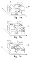
- Figures 3a-3c illustrates a re-stacking operation according to the present invention.
- a sub-section 30 of the block 20 described in connection with figure 2 comprises in this embodiment twenty containers arranged in an area with two by four containers wherein the maximum height is four containers.
- a three dimensional space is created having thirty two available positions.
- a single crane (not shown) moves a container at the time as defined by the required container moves arranged in a queue.
- the queue comprises a number of calculated container moves to perform the re-stacking according to the invention.
- Re-stacking is normally performed to put the containers within the sub-section at a more favorable position compared to the current position. This task is performed when there is no new container to be inserted into the sub-section 30, and when no container is to be removed from the sub-section 30. Insert and removal operation have priority over re-stacking operations and the process of re-stacking is preferably interrupted immediately when an order to insert or remove a container is received by the CCU from the PLS.
- the CCU calculates a value R for each container present within the sub-section 30.
- the calculated value R is based on: time until removal (TUR) of the container from the block, and time for moving (TFM) the container from the current position (CP) to a selected external output position (OUT).
- TUR time until removal
- TFM time for moving
- the calculated value R for each container is a measure of how optimal the current position of the container is compared to all other containers in the sub-section.
- a goal of the present invention is to reduce the sum of the calculated values R for all containers within the sub-section, and therefore the container with one of the highest values R is normally selected to be moved.
- Figure 3a illustrates the case when container "1" at current position CP 1 is selected.
- Alternative positions (AP) are identified and a corresponding value R new is calculated for each AP to identify a new position NP 1 for the selected container "1", as marked with dashed lines.
- a more detailed description of how to calculate the value R new and select NP 1 from the plurality of AP can be found below.
- container “A” positioned above container “1” needs to be relocated to a relocation position RP A from its current position CP A , as shown in figure 3a .
- Available relocation positions (ARP) are identified and a corresponding R relocate is calculated for each ARP to identify the relocation position RP 1 for container "A", as marked with dotted lines.
- a more detailed description of how to calculate the value R relocate and select RP 1 from the plurality of ARP can be found below.
- This queue is assigned to the crane (only one crane present in this example) and the first task is initiated, i.e. to move container A from its current position to the selected relocation position.
- the CCU thereafter selects another container “2", preferably the container having the second highest value "R”, which is positioned at CP 2 as illustrated in figure 3b .
- a new position NP 2 for container “2” is identified and selected, as marked with dashed lines.
- container "B" positioned above container "2” needs to be relocated to a relocation position RP B from its current position CP B , as shown in figure 3b .
- the relocation position RP B is identified and selected for container "B", as marked with dotted lines
- the status field indicates that the crane presently is busy with performing task 1.
- the crane performs the next task in the queue, i.e. first moving container “1” to its new position and thereafter moving container “B” to its relocation position, or first moving container “B” to its relocation position and thereafter moving container “1” to its new position dependent on which queue is assigned to the crane by the CCU.
- Container "3" is selected to be moved from its current position CP 3 to a new position NP 3 and container “4" is selected to be moved from its current position CP 4 to a new position NP 4 , as illustrated by the dashed lines in figure 3c .
- No other container needs to be moved in order to move the selected containers, but container “1” needs to be moved before container “3” can be moved into its new position NP 3 .
- Container "4" can not be moved into its new position NP 4 until container "3" has been moved its new position NP 3 .
- Figure 3c illustrates the positions of the container in the sub-section 30 after the completion of the move of container "1".
- the memory which is accessible to the CCU contains the current position of each container, and when the move is completed (as indicated by "done" in the status field), the current position of the moved containers are updated in the memory as indicated in the comments field.
- the re-stacking operation continues until the sum of the calculated values R for all containers present within the sub-section 30 is minimized, or until the re-stacking operation is interrupted by an insert operation or removal operation.
- the calculated value R is updated for each container that is affected by the move of the selected container to a new position before another container is selected.
- the calculated value of the container positioned below the relocation position RP A for container “A” should be updated, as well as the calculated value for the containers positioned below the new position NP 1 for container "1". These updated values will increase as a result of the additional container on top. The updated values will then be taken into consideration when selecting the next container to be moved. It is possible that the next container will be a container positioned below the new position NP 1 for container "1", and that container needs to be moved before container "1" can be moved. These parameters are preferably taken into consideration when selecting the new position NP 1 for container "1" from the plurality of alternative positions, as described in more detail below.
- Container parameters such as CP i , TUR i , OUT i , type, size, etc, are stored in the memory.
- the current position CP i of each container i is updated when the container is moved, but may also be updated regularly if the crane is provided with a means to verify the container ID when moving across the sub-section.
- Such a means may involve bar code reader system, transponder system, image recognition system, etc.
- the calculated value R for a container is based on TUR and on a parameter "time for moving” (TFM), which is determined based on the current position and the output position.
- TFM is calculated as the estimated time to move the selected container from its current position to a desired output position. Intermediately positioned containers between CP and OUT may affect the calculated TFM. It is preferred that TFM also is based on time for relocating (TFR) containers, such as container "A" and container “B” described in connection with figures 3a-3c , to facilitate the move of the selected container.
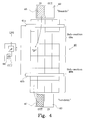
- Figure 4 shows a top view of a block 40 serviced by two cranes 41a and 41b.
- An area 42, 43 not being a part of the block 40 is provided on each side of the block, each area is provided with an output position OUT and an input position IN.
- a crane control unit CCU comprising a microprocessor ⁇ P and an internal memory 44, communicates with the cranes 41a and 41b.
- An external command center EEC such as a Port Logistics System, communicates with the CCU to initiate insert operation of a container into the block 40 using one of the available input positions, or to initiate a removal operation of a container from the block 40 to one of the available output positions.
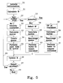
- the optimization process of block 40 is described in connection with figure 5 , wherein the process starts at step 50 when the optimization is initiated.
- a value R is therefore calculated in step 51, which reflects the time it takes to move each container to the correct output position from a position within the block (or sub-section if not the entire block is selected).
- R is based on, as mentioned above, time until removal (TUR) of the container from the block, and time for moving (TFM) the container from the current position (CP) to a selected external output position (OUT).
- TUR and desired OUT is provided from PLS, or calculated, when the container is inserted.
- the PLS may also supply this information at a later stage(see below).
- TFM may be based on the time for relocating (TFR) containers to facilitate the move of containers located below.
- TFR time for relocating
- TFM for a container being located beneath two containers will include TFR compared to a container situated on top of a stack of containers.
- TUR for most containers within a block is much higher than TFM, and TUR will therefore be an essential parameter for the optimization process.
- the value R should be considered to be a cost function that is attached to each container representing the time it would take to transport this particular container from its current position to the position where it is most likely going to be removed from the block (preferably taking into account that other containers stacked on top of this one have to be removed first). Weights are thereafter introduced to give higher cost to containers that are due for delivery soon.
- the value R is stored in a memory 44 arranged within the CCU and the process continue to step 52, in which CCU checks if there are any orders from the PLS to insert a container in the block 40 or to remove a container from the block. If there is an order to interrupt the re-stacking process, the process continues to step 53 in which the CCU determines the type of interrupt process. The steps associated with insert operation and removal operation is described below.
- step 62 the process continues to step 62 to perform a re-stacking operation by selecting a container.
- the container having the highest value R (or cost function) is preferably selected.
- Alternative positions (APs) for the selected container is thereafter identified within the block, as described in connection with figures 3a-3c , and a new value R new is calculated for each AP as the values R was calculated in step 51.
- a new position for the selected container is selected from the AP based on: the calculated value R for its CP, the calculated new value R new for its AP, and a travel cost (TC) based on time for moving the container from CP to each AP.
- TC travel cost
- TC is preferably further based on time for relocating containers to facilitate the move of the selected container to NP.
- the selection of NP is based on reducing, preferably minimizing, a cost C for the selected container:
- the selected container is the container that will decrease the sum of the value R for all containers when the selected container has been moved to NP. In that case a new value R new for every alternative position for all containers in the block needs to be calculated before a container can be selected. The calculations to find NP for each container in the block is performed as described above.
- step 63 in which necessary moves are calculated in order to be able to move the selected container from CP to NP. These moves may include relocating containers that are stacked on top of the selected container, etc.
- RP relocation position
- ARP available relocation positions
- the CCU When the moves have been calculated in step 63, the CCU create a queue in step 64 for each crane 41a, 41b to perform the tasks. If there are pending tasks in the queue, these may be taken under consideration when creating the queues, as described above in connection with figures 3a-3c . It is also possible to rearrange tasks between the queues of the cranes, to further reduce the time needed to perform the tasks.
- step 65 the cranes perform the next task assigned to each queue and the process continues to step 66 in which the database containing the cost function R is updated.
- the calculated container moves will affect the calculated value R for some containers in the block. These values are preferably updated before the process continues to step 67. However, it is possible to omit step 66 in favor of including step 51 if another container should be selected, which is decided in step 67. If another container should be selected the process is fed back through arrow 69 to step 52 (unless step 66 was omitted, then the process is fed back to step 51). If no other container should be selected the process ends in step 68.
- the order sent from the PLS comprises:
- TUR is preferably estimated using the stored TUR for containers located within the block 40 if the TUR for the container to be inserted is unknown to the system, and the estimated value is stored in the memory 44. The estimation is calculated as an average value of the stored TUR for containers within the block 40. If OUT is not provided in the order to insert the container, OUT is preferably selected to be a central position of the block 40. The PLS may naturally update TUR and OUT for a given container at any time before it has been removed from the block 40.
- An insert position is selected by the CCU based on a calculated value R insert for each available insert position (AIP) in the block, and a calculated travel cost (TC).
- R insert is based on the same parameters as the value R, see above, with the exception that TFM is selected to be the time for moving the container from each AIP to the OUT.
- TC is based on the time for moving the new container from the external input position (IN) to each AIP.
- the insert position (IP) for the new container may further be selected based on an updated calculated value R for each container affected by inserting the container at each AIP, and with the aim of minimizing the sum of the updated calculated values R and the insert value R insert for the selected IP.
- the selection of the insert position (IP) is based on reducing (preferably minimizing) a cost C insert for the inserted container:
- FIG. 4 An order to insert container 45 from the external input position IN at the "seaside" is received from PLS to CCU and the re-stacking operation is interrupted.
- Each crane has a queue of tasks to perform, as described in connection with figures 3a-3c .
- the system is preferably configured to prioritize the insert operation and the tasks in the crane 41a, operating at the "seaside", will only be performed until the CCU has selected an IP.
- the queue assigned to crane 41b is not affected by the insert operation, and the block may be considered to be divided into dynamical sub-sections 46a and 46b.
- Each crane service a sub-section of the block 40, which sub-sections may be overlapping.
- the insert position is selected, as described above, and the tasks in the queue assigned to crane 41a are rearranged to include the moves required to insert the new container at IP as fast as possible.
- Tasks assigned to crane 41b needs to be taken into consideration when rearranging the tasks in the queue for crane 41a to avoid unnecessary delay and risk for collision between the cranes.
- the moves required inserting the container in the block are preferably prioritized in the queue in step 56.
- the container moves performed in step 57 are preferably carried out until the container has been inserted in the block 40 before the process continues to step 66 and the value R is updated and stored in the memory 44 for each affected container within the block.
- the order sent from the PLS comprises:
- the moves required removing the container from the block are preferably prioritized in the queue in step 60, and the selection of RP for each container that needs to be relocated in step 59 is based on a calculated relocation value (R relocate ) for available relocation position (ARP) as described in more detail above.
- the container moves performed in step 61 are preferably carried out until the container has been removed from the block 40 before the process continues to step 66 and the value R is updated and stored in the memory 44 for each affected container within the block.
- the relocation position is based on reducing, preferably minimizing, a cost C relocate for each additional container:
- the aim of the optimization is to reduce the sum of the calculated values R (cost function) for all containers present within each block, or a sub-section of the block.
- the described process is preferably implemented as a computer program configured to perform, when executed on a computer, an optimization of the position of a plurality of containers in a block, or sub-section.
- a computer-readable medium is preferably encoded with the computer program.
- the invention also relates to a system for optimizing the position of a plurality of containers in a block (or sub-section of a block).
- the system is adapted to control at least one crane 21; 41a, 41b configured to move said containers within said block (or sub-section) and is further provided with a crane control unit CCU that is configured to perform the optimization process.
Landscapes
- Engineering & Computer Science (AREA)
- Business, Economics & Management (AREA)
- Economics (AREA)
- Marketing (AREA)
- Quality & Reliability (AREA)
- Mechanical Engineering (AREA)
- Entrepreneurship & Innovation (AREA)
- Human Resources & Organizations (AREA)
- Automation & Control Theory (AREA)
- Operations Research (AREA)
- Development Economics (AREA)
- Strategic Management (AREA)
- Tourism & Hospitality (AREA)
- Physics & Mathematics (AREA)
- General Business, Economics & Management (AREA)
- General Physics & Mathematics (AREA)
- Theoretical Computer Science (AREA)
- Control And Safety Of Cranes (AREA)
- Warehouses Or Storage Devices (AREA)
Abstract
Description
- The present invention relates to a method for optimizing the position of a plurality of containers in a block, especially a container block in a container port. The invention is also related to software and a system configured to perform said optimization.
- A very large part of all traded goods in the world is transported over sea by container ships. The ever increasing amount of international trade results in higher demands of container terminals all over the world to process (import/ store/ export) more goods with an increased speed. The demand on increased throughput capacity of container terminals often implies making very expensive investments. Such investments could be in terms of larger blocks (if even possible) and more cranes, other transport vehicles and complex and expensive computer systems. The reason for this is to be able to serve more import/export activities, and the resulting intermediate storage without incurring longer, costly delays in either end. For many small to medium sized terminals such investments might be too large to bear. Improved planning and handling of the storage blocks in a terminal has a great potential to increase the overall terminal throughput since this part is often a bottleneck in the whole inter modal transport system.
- A system to optimize the block handling operations could increase the capacity of terminals too small to afford the high investment costs of large facility improvements. In addition, larger terminals could of course also benefit from a system that increases their capacity and effectiveness.
- The traditional solution is to have a logistics system for the entire port handling all blocks and loading/unloading of the ships. The port logistics system determines in which block a certain container should be stored and communicates this information to a crane control system that inserts the container in the appropriate block. The export of a specific container is ordered by the port logistics system and the information is communicated to the crane control system for the appropriate block and the specific container is removed from the block where it has been stored.
- In the published US application
US2006/0182527, by Ranstrom et al ., a system has been disclosed in a port logistics system which controls the movements of containers within each block by assigning orders to the cranes to perform a specific task. - A drawback of the prior art system is that only the port logistics system has an overall picture of each block and the crane available for moving the containers within each block performs the assigned orders whenever the port logistics system detects a container to move to a more favorable position. A small port without an expensive port logistics system having only one or a few container blocks will lack the possibility to use the unused capacity of the crane to optimize the position of each container within the block.
- Another drawback is that each crane performs the assigned orders in the order they are assigned to the crane, which may introduce extensive crane motion before the next assigned order may be expedited.
- Thus, there is a need to provide an improved system for optimizing the position of each container in a block without the presence of a port logistics system.
- An object of the present invention is to provide a method that provides an optimization process for the stored containers in a block which reduces the drawbacks of the prior art systems.
- In this invention we propose a more decentralized approach where the crane control system in a block takes care of the container storage optimization for this block. The port logistics system (if present) still determines in which block a certain container should be stored and communicates with the local block optimization system, called crane control unit. The crane control unit has three major tasks. It should optimize:
- container insert, i.e. find an optimal placement for new containers whether delivered by land or by sea
- container removal, i.e. in shortest possible time remove a container from the block
- container re-stacking, i.e. during times of low crane load relocate containers to more favourable positions
- The crane control calculates required container moves to handle these tasks and in order to make it efficient, a queue of container moves is assigned to each crane. The content of the queue, i.e. the order of the container moves, are reviewed and the queue rearranged in such a way to reduce the time needed to perform the tasks.
- In all these tasks the optimization takes a number of issues into account, such as:
- the actual or estimated time of removal for containers that are moved
- to which position the container will eventually be delivered. In particular if it is to be transported next by land or by sea
- the type and size of container
- An advantage with the present invention is that the crane capacity is better used compared to prior art solutions.
- Another advantage is that an optimization of a container block may be achieved even though a port logistics system is not present.
- Still another advantage with the present invention is that the operating speed of the cranes may be reduced, in order to reduce wear and energy consumptions, since the crane control unit has a more complete knowledge compared to prior art systems.
- Additional objects and advantages will become apparent for a skilled person in the art from the detailed description.
-
-
Fig. 1 shows an overview of a container port. -
Fig. 2 shows a container block with one crane illustrating insert, removal and re-stacking operation according to the invention. -
Figs. 3a-3c illustrates a re-stacking operation according to the present invention. -
Fig. 4 shows a container block with two cranes illustrating insert, removal and re-stacking operation according to the invention. -
Fig. 5 is a flow chart of the process for insert, removal and re-stacking operation according to the invention. -
Figure 1 shows aport 11 provided with a prior art port logistics system PLS that controls all movements of container blocks in the port. Ships 2 arrive to unload orload containers 1, and the containers are stored, in this embodiment, in fourblocks 10. The PLS controls the cranes that unload/load the ships through a communication bus 3, and an unloaded container is brought from a ship via a transport rail 4 to a block selected by the PLS.Cranes 5 that are dedicated to a block, and controlled by the PLS, move the unloaded container into a suitable position within the block. A container that is going to be loaded onto a ship is collected by thecranes 5 and moved to the transport rail 4 to be transported to theship 2. The PLS issues orders to each crane and these orders are arranged in a queue for each crane. The same applies when atruck 6 loads or unloads a container on the "landside" 7. -
Figure 2 shows a first embodiment of the present invention applied to ablock 20 of amultiple containers 1 stacked in a three dimensional space. Asingle crane 21 is provided to move the containers within the block (re-stacking operation) as illustrated by thearrow 24, inserting a container into the block (insert operation) from aninput position 22 as illustrated by thearrow 25, and removing a container from the block (removal operation) to anoutput position 23, as illustrated by thearrow 26. Input and output positions are provided outside theblock 20 in a dedicated space 27 for the "landside" of the block, and adedicated space 28 for the "seaside" of the block. A crane control unit (CCU) configured to communicate with the port logistics system (PLS) controls the movement of the crane by assigning container moves to a queue. The PLS informs the CCU of which block a container should be stored in and the CCU controls the handling of the containers within theblock 20, and the insert and removal operations from the externaldedicated spaces 27 and 28 in which theinput position 22 andoutput position 23 are located. The CCU is provided with an internal memory or anexternal memory 29 is accessible to the CCU. Information regarding container identification, current position (CP) of each container, time-until-removal TUR, and desired output position (OUT) are stored in thememory 29. There are normally several output positions and input positions available in each externaldedicated space 27 and 28. - It should be noted that the invention may be implemented for a
sub-section 30, as described in connection withfigures 3a-3c of an entire block. A block may be dynamically divided into sub-sections dependent on the number of cranes and tasks assigned to each crane. This will become obvious from the description in connection withfigure 4 . -
Figures 3a-3c illustrates a re-stacking operation according to the present invention. Asub-section 30 of theblock 20 described in connection withfigure 2 comprises in this embodiment twenty containers arranged in an area with two by four containers wherein the maximum height is four containers. A three dimensional space is created having thirty two available positions. A single crane (not shown) moves a container at the time as defined by the required container moves arranged in a queue. The queue comprises a number of calculated container moves to perform the re-stacking according to the invention. - Re-stacking is normally performed to put the containers within the sub-section at a more favorable position compared to the current position. This task is performed when there is no new container to be inserted into the
sub-section 30, and when no container is to be removed from thesub-section 30. Insert and removal operation have priority over re-stacking operations and the process of re-stacking is preferably interrupted immediately when an order to insert or remove a container is received by the CCU from the PLS. - The principal operation of the re-stacking procedure is described in connection with
figures 3a-3c . Before the crane can start to move containers from their current position (CP) to a new position (NP), the CCU calculates a value R for each container present within thesub-section 30. The calculated value R is based on: time until removal (TUR) of the container from the block, and time for moving (TFM) the container from the current position (CP) to a selected external output position (OUT). A more detailed description of how to calculate the value R can be found below. - The calculated value R for each container is a measure of how optimal the current position of the container is compared to all other containers in the sub-section. A goal of the present invention is to reduce the sum of the calculated values R for all containers within the sub-section, and therefore the container with one of the highest values R is normally selected to be moved.
Figure 3a illustrates the case when container "1" at current position CP1 is selected. Alternative positions (AP) are identified and a corresponding value Rnew is calculated for each AP to identify a new position NP1 for the selected container "1", as marked with dashed lines. A more detailed description of how to calculate the value Rnew and select NP1 from the plurality of AP can be found below. - In order to be able to move container "1" from its current position, container "A" positioned above container "1" needs to be relocated to a relocation position RPA from its current position CPA, as shown in
figure 3a . Available relocation positions (ARP) are identified and a corresponding Rrelocate is calculated for each ARP to identify the relocation position RP1 for container "A", as marked with dotted lines. A more detailed description of how to calculate the value Rrelocate and select RP1 from the plurality of ARP can be found below. - The required container moves are calculated and a queue of container moves is now created with the following appearance:
Task ID Move 1 "A" CPA -> RP A2 "1" CP1 -> NP1 - This queue is assigned to the crane (only one crane present in this example) and the first task is initiated, i.e. to move container A from its current position to the selected relocation position. The CCU thereafter selects another container "2", preferably the container having the second highest value "R", which is positioned at CP2 as illustrated in
figure 3b . A new position NP2 for container "2" is identified and selected, as marked with dashed lines. In order to be able to move container "2" from its current position, container "B" positioned above container "2" needs to be relocated to a relocation position RPB from its current position CPB, as shown infigure 3b . The relocation position RPB is identified and selected for container "B", as marked with dotted lines - The required container moves for moving container "2" from its current position CP2 to the new position NP2 are calculated:
Calculated moves for container "2" Task ID Move 1 "B" CPB -> RP B2 "2" CP2 -> NP2 - These container moves could either be added in the end of the queued tasks for the crane, such as:
Queue for crane Task ID Move Status 1 "A" CPA -> RPA moving 2 "1" CP1 -> NP1 3 "B" CPB -> RPB 4 "2" CP2 -> NP2 - The status field indicates that the crane presently is busy with performing
task 1. - In some circumstances it may be more efficient to rearrange the order of the tasks to take advantage of the cranes actual position after completing the task it presently is occupied with. In this case it may be more advantageous to rearrange the container moves for container "1" and "B". The aim of the rearranging is to minimize, or at least reduce, the required time to perform the tasks in the queue for the crane. This result in a modified queue of container moves assigned to the crane by the CCU.
Modified queue for crane Task ID Move Status 1 "A" CPA -> RPA moving 2 "B" CPB -> RPB 3 "1" CP1 -> NP1 4 "2" CP2 -> NP2 - When the task of moving container "A" has been completed, as illustrated in
figure 3b , the crane performs the next task in the queue, i.e. first moving container "1" to its new position and thereafter moving container "B" to its relocation position, or first moving container "B" to its relocation position and thereafter moving container "1" to its new position dependent on which queue is assigned to the crane by the CCU. - At the same time as the crane performs the assigned tasks in the queue, the CCU continues to select containers to be moved to "optimize" the positions of the containers in the
sub-section 30. Container "3" is selected to be moved from its current position CP3 to a new position NP3 and container "4" is selected to be moved from its current position CP4 to a new position NP4, as illustrated by the dashed lines infigure 3c . No other container needs to be moved in order to move the selected containers, but container "1" needs to be moved before container "3" can be moved into its new position NP3. Container "4" can not be moved into its new position NP4 until container "3" has been moved its new position NP3. As an example, the tasks in the queue for the crane are rearranged and the container moves for container "3" and "4" are added as follows:New queue for crane Task ID Move Status Comments - "A" CPA -> RPA done (RPA is now CPA for container "A") - "B" CPB -> RPB done (RPB is now CPB for container "B") 1 "1" CP1 -> NP1 moving 2 "3" CP3 -> RP3 3 "2" CP2 -> NP2 4 "4" CP4 -> NP4 - The completed moves are preferably removed from the queue, but are included above to clarify which moves have been performed.
Figure 3c illustrates the positions of the container in thesub-section 30 after the completion of the move of container "1". The memory which is accessible to the CCU contains the current position of each container, and when the move is completed (as indicated by "done" in the status field), the current position of the moved containers are updated in the memory as indicated in the comments field. - The re-stacking operation continues until the sum of the calculated values R for all containers present within the
sub-section 30 is minimized, or until the re-stacking operation is interrupted by an insert operation or removal operation. - In a preferred embodiment, the calculated value R is updated for each container that is affected by the move of the selected container to a new position before another container is selected. In the example illustrated in connection with
figures 3a-3c , the calculated value of the container positioned below the relocation position RPA for container "A" should be updated, as well as the calculated value for the containers positioned below the new position NP1 for container "1". These updated values will increase as a result of the additional container on top. The updated values will then be taken into consideration when selecting the next container to be moved. It is possible that the next container will be a container positioned below the new position NP1 for container "1", and that container needs to be moved before container "1" can be moved. These parameters are preferably taken into consideration when selecting the new position NP1 for container "1" from the plurality of alternative positions, as described in more detail below. - Container parameters, such as CPi, TURi, OUTi, type, size, etc, are stored in the memory. The current position CPi of each container i is updated when the container is moved, but may also be updated regularly if the crane is provided with a means to verify the container ID when moving across the sub-section. Such a means may involve bar code reader system, transponder system, image recognition system, etc.
- The calculated value R for a container is based on TUR and on a parameter "time for moving" (TFM), which is determined based on the current position and the output position. The current position and the output position are container parameters stored in the memory. TFM is calculated as the estimated time to move the selected container from its current position to a desired output position. Intermediately positioned containers between CP and OUT may affect the calculated TFM. It is preferred that TFM also is based on time for relocating (TFR) containers, such as container "A" and container "B" described in connection with
figures 3a-3c , to facilitate the move of the selected container. -
Figure 4 shows a top view of ablock 40 serviced by twocranes area block 40 is provided on each side of the block, each area is provided with an output position OUT and an input position IN. A crane control unit CCU, comprising a microprocessor µP and aninternal memory 44, communicates with thecranes - An external command center EEC, such as a Port Logistics System, communicates with the CCU to initiate insert operation of a container into the
block 40 using one of the available input positions, or to initiate a removal operation of a container from theblock 40 to one of the available output positions. The optimization process ofblock 40 is described in connection withfigure 5 , wherein the process starts atstep 50 when the optimization is initiated. In order to effectively optimize the position of the containers within a block it is necessary for the system to have knowledge of a parameter indicative of the suitability to position each container at a certain position within the block. A value R is therefore calculated instep 51, which reflects the time it takes to move each container to the correct output position from a position within the block (or sub-section if not the entire block is selected). - R is based on, as mentioned above, time until removal (TUR) of the container from the block, and time for moving (TFM) the container from the current position (CP) to a selected external output position (OUT). TUR and desired OUT is provided from PLS, or calculated, when the container is inserted. The PLS may also supply this information at a later stage(see below).
- Furthermore, TFM may be based on the time for relocating (TFR) containers to facilitate the move of containers located below. TFM for a container being located beneath two containers will include TFR compared to a container situated on top of a stack of containers. TUR for most containers within a block is much higher than TFM, and TUR will therefore be an essential parameter for the optimization process.
- The value R should be considered to be a cost function that is attached to each container representing the time it would take to transport this particular container from its current position to the position where it is most likely going to be removed from the block (preferably taking into account that other containers stacked on top of this one have to be removed first).
Weights are thereafter introduced to give higher cost to containers that are due for delivery soon. - The value R is stored in a
memory 44 arranged within the CCU and the process continue to step 52, in which CCU checks if there are any orders from the PLS to insert a container in theblock 40 or to remove a container from the block. If there is an order to interrupt the re-stacking process, the process continues to step 53 in which the CCU determines the type of interrupt process. The steps associated with insert operation and removal operation is described below. - If no orders are received from the PLS, the process continues to step 62 to perform a re-stacking operation by selecting a container. The container having the highest value R (or cost function) is preferably selected.
- Alternative positions (APs) for the selected container is thereafter identified within the block, as described in connection with
figures 3a-3c , and a new value Rnew is calculated for each AP as the values R was calculated instep 51. A new position for the selected container is selected from the AP based on: the calculated value R for its CP, the calculated new value Rnew for its AP, and a travel cost (TC) based on time for moving the container from CP to each AP. TC is preferably further based on time for relocating containers to facilitate the move of the selected container to NP. - In a further embodiment, the selection of NP is based on reducing, preferably minimizing, a cost C for the selected container:

- R(CP) is the calculated value at the current position,
- Rnew(APn) is the calculated new value at the nth alternative position
- K1 is a constant, preferably less than one (K1< 1)
- TCn is the calculated travel cost for moving said selected container from the current position to the nth alternative position, and
- N is the number of alternative positions available.
- In an alternative embodiment, the selected container is the container that will decrease the sum of the value R for all containers when the selected container has been moved to NP. In that case a new value Rnew for every alternative position for all containers in the block needs to be calculated before a container can be selected. The calculations to find NP for each container in the block is performed as described above.
- When a new position (NP) has been determined the process continues to step 63 in which necessary moves are calculated in order to be able to move the selected container from CP to NP. These moves may include relocating containers that are stacked on top of the selected container, etc. In order to select a suitable relocation position (RP) for a container that needs to be relocated, a value, cost function, Rrelocate has to be calculated for every available relocation positions (ARP), as described above. The calculation of Rrelocate is based on the same parameters as the calculation of R for all containers in
step 51 and the selection of RP is described in more detail below. - When the moves have been calculated in
step 63, the CCU create a queue instep 64 for eachcrane figures 3a-3c . It is also possible to rearrange tasks between the queues of the cranes, to further reduce the time needed to perform the tasks. - In
step 65 the cranes perform the next task assigned to each queue and the process continues to step 66 in which the database containing the cost function R is updated. The calculated container moves will affect the calculated value R for some containers in the block. These values are preferably updated before the process continues to step 67. However, it is possible to omitstep 66 in favor of includingstep 51 if another container should be selected, which is decided instep 67. If another container should be selected the process is fed back througharrow 69 to step 52 (unlessstep 66 was omitted, then the process is fed back to step 51). If no other container should be selected the process ends instep 68. - Interrupt will appear when an order to initiate an insert operation of a
new container 45 into theblock 40 is received from the PLS. The order sent from the PLS comprises: - Container ID,
- Input position (Seaside/landside) IN
- Furthermore, information regarding "time until removal" TUR and desired output position OUT may be included in the order to insert the container into the block. These container parameters are not essential to perform the insert operation, but the knowledge of TUR and OUT will improve future re-stacking operations of the block since the
new container 45 may be positioned in a more favorable position during the insert operation. TUR is preferably estimated using the stored TUR for containers located within theblock 40 if the TUR for the container to be inserted is unknown to the system, and the estimated value is stored in thememory 44. The estimation is calculated as an average value of the stored TUR for containers within theblock 40. If OUT is not provided in the order to insert the container, OUT is preferably selected to be a central position of theblock 40. The PLS may naturally update TUR and OUT for a given container at any time before it has been removed from theblock 40. - An insert position is selected by the CCU based on a calculated value Rinsert for each available insert position (AIP) in the block, and a calculated travel cost (TC). Rinsert is based on the same parameters as the value R, see above, with the exception that TFM is selected to be the time for moving the container from each AIP to the OUT. TC is based on the time for moving the new container from the external input position (IN) to each AIP.
- The insert position (IP) for the new container may further be selected based on an updated calculated value R for each container affected by inserting the container at each AIP, and with the aim of minimizing the sum of the updated calculated values R and the insert value Rinsert for the selected IP.
- In an alternative embodiment, the selection of the insert position (IP) is based on reducing (preferably minimizing) a cost Cinsert for the inserted container:

wherein: - Rinsert(AIPr) is the calculated insert value at the rth available insert position,
- K3 is a constant, preferably higher than one (K3>1)
- TCr is the calculated travel cost for moving the additional container from the current position to the rth available insert position, and
- R is the number of available insert positions.
- This may be exemplified with reference to
figure 4 . An order to insertcontainer 45 from the external input position IN at the "seaside" is received from PLS to CCU and the re-stacking operation is interrupted. Each crane has a queue of tasks to perform, as described in connection withfigures 3a-3c . The system is preferably configured to prioritize the insert operation and the tasks in thecrane 41a, operating at the "seaside", will only be performed until the CCU has selected an IP. The queue assigned tocrane 41b is not affected by the insert operation, and the block may be considered to be divided intodynamical sub-sections block 40, which sub-sections may be overlapping. - The insert position is selected, as described above, and the tasks in the queue assigned to
crane 41a are rearranged to include the moves required to insert the new container at IP as fast as possible. Tasks assigned tocrane 41b needs to be taken into consideration when rearranging the tasks in the queue forcrane 41a to avoid unnecessary delay and risk for collision between the cranes. - The process initiated by the order to insert a container is described in connection with
figure 5 and comprises: - Selecting an insert position (IP),
step 54, - calculating the number of container moves required facilitating the move of the container to be inserted from the external input position (IN) to an insert position (IP) within the sub-section of said block,
step 55, - introducing the required number of container moves in the queue for each crane,
step 56, and - performing the container moves as arranged in the queue by controlling said at least one crane,
step 57. - The moves required inserting the container in the block are preferably prioritized in the queue in
step 56. The container moves performed instep 57 are preferably carried out until the container has been inserted in theblock 40 before the process continues to step 66 and the value R is updated and stored in thememory 44 for each affected container within the block. - Interrupt will also appear when an order to initiate a removal operation of a
container 47 within theblock 40 is received from the PLS. The order sent from the PLS comprises: - Container ID,
- Output position (Seaside/landside) OUT
- No other information is needed for CCU to be able to calculate the moves necessary to remove the selected container from the block to the correct output position OUT. It should be noted that the previously stored desired output position may differ from the output position contained in the order to remove the container. If the selected container is positioned below another container within the block, this container needs to be removed to a relocation position. This procedure is similar to the procedure required to move container within the block during re-stacking operations, as described in connection with
figures 3a-3c . The selection of a relocation position (RP) will affect the future re-stacking operations that will commence as soon as the interrupt operation has been completed. A more detailed description of how to select a suitable RP can be found below. - The process initiated by the order to remove a container is described in connection with
figure 5 and comprises the steps after step 53: - determining the current position (CP) of the container to be removed from the block,
step 58, - calculating a number of container moves required facilitating the move of the container to be removed, preferably including relocating any containers arranged above the container to be removed to a respective relocation position (RP), and moving the container to be removed to the selected external output position (OUT),
step 59, - introducing the required number of container moves in the queue for one or both cranes (if necessary),
step 60, and - performing the container moves as arranged in the queue by controlling each crane,
step 61. - The moves required removing the container from the block are preferably prioritized in the queue in
step 60, and the selection of RP for each container that needs to be relocated instep 59 is based on a calculated relocation value (Rrelocate) for available relocation position (ARP) as described in more detail above. The container moves performed instep 61 are preferably carried out until the container has been removed from theblock 40 before the process continues to step 66 and the value R is updated and stored in thememory 44 for each affected container within the block. - In an alternative embodiment the relocation position (RP) is based on reducing, preferably minimizing, a cost Crelocate for each additional container:

wherein: - R(CP) is the calculated value at the current position,
- Rrelocate(ARPm) is the calculated relocation value at the mth available relocation position
- K2 is a constant, preferably higher than one (K2>1)
- TCm is the calculated travel cost for moving the additional container from the current position to the mth available relocation position, and
- M is the number of available relocation positions.
- The aim of the optimization is to reduce the sum of the calculated values R (cost function) for all containers present within each block, or a sub-section of the block. The described process is preferably implemented as a computer program configured to perform, when executed on a computer, an optimization of the position of a plurality of containers in a block, or sub-section. A computer-readable medium is preferably encoded with the computer program.
- The invention also relates to a system for optimizing the position of a plurality of containers in a block (or sub-section of a block). The system is adapted to control at least one
crane 21; 41a, 41b configured to move said containers within said block (or sub-section) and is further provided with a crane control unit CCU that is configured to perform the optimization process.
Claims (34)
- A method for optimizing the position of a plurality of containers in a block (20), wherein at least one crane (21) is configured to move said containers, characterized by providing a crane control unit (CCU) to said block (20; 30) in which the following steps are performed:A identifying a selected container (i) to be moved from a current position (Cp) within a sub-section (30) of said block to a new position (NP) within the sub-section (30),B calculating a number of container moves required facilitating the move of the selected container in step A,C arranging the required number of container moves in a queue for each crane (21), andD performing the container moves as arranged in the queue by controlling said at least one crane (21).
- The method according to claim 1, wherein said method further comprises:E repeating steps A-E for another selected container within the sub-section.
- The method according to claim 2, wherein step C further comprises rearranging the container moves in the queue to reduce required time to perform the container moves in the queue of each crane (21).
- The method according to claim 3, wherein the aim of step C is to minimize the required time to perform the container moves in the queue of each crane (21).
- The method according to any of claims 3-4, wherein the sub-section is serviced by two cranes connected to the crane control unit (CCU), and step C further comprises rearranging the container moves between the queues of the cranes.
- The method according to any of claim 1-5, wherein the method comprises selecting the sub-section (30) to constitute the entire block.
- The method according to any of claims 1-6, wherein the identification in step A is performed by:a) determining the current position (CP) of each container within a sub-section of said block,b) calculating a value (R) for each container in said sub-section based on:- time until removal (TUR) of the container from the block, and- time for moving (TFM) the container from the current position (Cp) to a selected external output position (OUT),c) identifying a number of alternative positions (AP's) within the sub-section for a selected container,d) calculating a new value (Rnew) for the selected container based on the same parameters as the calculated value (R) in step b) for each alternative position (AP), ande) selecting a new position (NP) for the container from the number of alternative positions (AP's), based on:- the calculated value (R) for its current position (Cp),- the calculated new values (Rnew) for its alternative positions (AP's), and- a calculated travel cost (TC) based on time for moving said container from the current position (Cp) to each alternative position (AP).
- The method according to claim 7, wherein said method further comprises:f) updating the calculated value (R) for each container affected by the move of the selected container to the new position (NP).
- The method according to any of claims 7 or 8, wherein the travel cost (TC) in step e) further is based on time for relocating containers to facilitate the move of the selected container to the new position (NP).
- The method according to any of claims 7-9, wherein the selection of the new position (NP) in step e) further is based on reducing a cost C for the selected container:

where n=1 to N- R(CP) is the calculated value at the current position,- Rnew(APn) is the calculated new value at the nth alternative position- K1 is a constant, preferably less than one (K1<1)- TCn is the calculated travel cost for moving said selected container from the current position to the nth alternative position, and- N is the number of alternative positions available. - The method according to claim 10, wherein the selection in step e) further is based on minimizing the cost C for the selected container.
- The method according to any of claims 7-11, wherein step c) further comprises selecting a container based on the calculated value (R) prior to identifying a number of alternative positions in step c).
- The method according to claim 12, wherein the container with the highest value (R) is selected in step c).
- The method according to any of claims 7-13, wherein said time for moving (TFM) further is based on time for relocating (TFR) containers to facilitate the move of the selected container in step b) and step d).
- The method according to any of claims 7-14, wherein the method further comprises relocating additional containers other than the selected container to facilitate the move to the new position (NP), each additional container is relocated to a relocation position (RP).
- The method according to claim 15, wherein the selection of the relocation position (RP) for each additional container is based on the same parameters as the selection of the new position in step e) for available relocation positions (ARP's) and a calculated relocation value (Rrelocate) for each available relocation position (ARP) based on the same parameters as the calculated value (R) in step b) for each available relocation position (ARP).
- The method according to any of claims 7-16, wherein the time until removal (TUR) for each container is given to the crane control unit (CCU) when each container enters the block, or the time until removal (TUR) is estimated using the stored time until removal (TUR) for the containers within the block if the time until removal for a container to be inserted is unknown when the container enters the block.
- The method according to claim 17, wherein said estimation of the time until removal (TUR) is an average value of the stored time until removal for the containers within the block accessible to the crane control unit (CCU).
- The method according to any of claims 7-18, wherein step a) comprises retrieving the current position (CP) of each container from a memory (DB) accessible to said crane control unit (CCU), said memory (DB) further comprises the latest calculated value (R) for each container at the current position (CP).
- The method according to claim 19, wherein the method further comprises confirming and updating the current position (CP) of each container in the memory (DB) each time a container is moved by retrieving the identity of the container.
- The method according to any of claims 1-20, wherein the optimization is interrupted when an order to remove a container from the block to a selected external output position (OUT) is received from an external command center (PLS), and the following steps are performed by the crane control unit (CCU) before the process restarts at step A):F determining the current position (CP) of the container to be removed from the block,G calculating a number of container moves required facilitating the move of the selected container in step F,H introducing the required number of container moves in the queue for each crane, andI performing the container moves as arranged in the queue by controlling said at least one crane.
- The method according to claim 21, wherein the moves required removing the container from the block are prioritized in the queue.
- The method according to claim 21 or 22, wherein the calculation in step G is based on:g) relocating any containers arranged above the container to be removed to a respective relocation position (RP), andh) moving the container to be removed to the selected external output position (OUT),
- The method according to claim 23, wherein the selection of the relocation position (RP) for each additional container in step h) is based on the same parameters as the selection of the new position in step e) for all available relocation positions (ARP's) and a calculated relocation value (Rrelocate) for each available relocation position (ARP) based on the same parameters as the calculated value (R) in step b) for each available relocation position (ARP).
- The method according to claim 24, wherein the selection of the relocation position (RP) in step h) further is based on reducing a cost C for each additional container:
 - R(CP) is the calculated value at the current position,- Rrelocate(ARPm) is the calculated relocation value at the mth available relocation position- K2 is a constant, preferably higher than one (K2>1)- TCm is the calculated travel cost for moving the additional container from the current position to the mth available relocation position, and- M is the number of available relocation positions.
 - The method according to any of claims 1-25, wherein the optimization is interrupted when an order to insert a container into the block from an external input position (IN) is received from an external command center (PLS), and the following steps is performed before the process restarts at step A):J calculating the number of container moves required facilitating the move of the container to be inserted from the external input position (IN) to an insert position (IP) within the sub-section of said block, andK introducing the required number of container moves in the queue for each crane, andL performing the container moves as arranged in the queue by controlling said at least one crane.
- The method according to claim 26, wherein the moves required inserting the container from the block are prioritized in the queue.
- The method according to claim 26 or 27, wherein the insert position (IP) for the container in step J is selected based on:- available insert positions (AIP's),- a value (Rinsert) for each available insert position (AIP) based on the same parameters as the calculated value (R) in step b) for each available insert position (AIP), and- a calculated travel cost (TC) based on time for moving said container from the external input position (IN) to each available insert position (AIP).
- The method according to claim 28, wherein the insert position (IP) for the container in step J further is selected based on:- the updated calculated value (R) for each container affected by inserting the container at each available insert position (AIP), and- the aim of minimizing the sum of the updated calculated values (R) and the insert value (Rinsert) for the selected insert position (IP).
- The method according to claim 29, wherein the selection of the insert position (IP) in step J) further is based on reducing a cost Cinsert for the inserted container:
 - Rinsert(AIPr) is the calculated insert value at the rth available insert position,- K3 is a constant, preferably higher than one (K3>1)- TCr is the calculated travel cost for moving the additional container from the current position to the rth available insert position, and- R is the number of available insert positions.
 - The method according any of claims 1-30, wherein the aim of the optimization is reducing the sum of the calculated values (R) for all containers present within the sub-section.
- A computer program configured to perform, when executed on a computer, an optimization of the position of a plurality of containers in a block, or sub-section of a block, according to any of claims 1-31.
- A computer-readable medium encoded with the computer program according to claim 32.
- A system for optimizing the position of a plurality of containers in a block, said system being adapted to control at least one crane (21; 41a, 41b) configured to move said containers within said block, characterized in that said system comprises a crane control unit (CCU) that is configured to perform the method according to any of claims 1-31.
Priority Applications (7)
| Application Number | Priority Date | Filing Date | Title |
|---|---|---|---|
| DK07110565.4T DK2006237T3 (en) | 2007-06-19 | 2007-06-19 | Method and system for optimizing containers in one block |
| PT71105654T PT2006237E (en) | 2007-06-19 | 2007-06-19 | A method and system for optimizing containers in a block |
| ES07110565T ES2400525T3 (en) | 2007-06-19 | 2007-06-19 | A method and system to optimize containers in a block |
| EP07110565A EP2006237B1 (en) | 2007-06-19 | 2007-06-19 | A method and system for optimizing containers in a block |
| SG200803268-2A SG148915A1 (en) | 2007-06-19 | 2008-04-28 | A method and system for optimizing containers in a block |
| CN200810126945.2A CN101329579B (en) | 2007-06-19 | 2008-06-18 | A method and system for optimizing containers in a block |
| US12/142,596 US8090470B2 (en) | 2007-06-19 | 2008-06-19 | Method and system for optimizing containers in a block |
Applications Claiming Priority (1)
| Application Number | Priority Date | Filing Date | Title |
|---|---|---|---|
| EP07110565A EP2006237B1 (en) | 2007-06-19 | 2007-06-19 | A method and system for optimizing containers in a block |
Publications (2)
| Publication Number | Publication Date |
|---|---|
| EP2006237A1 true EP2006237A1 (en) | 2008-12-24 |
| EP2006237B1 EP2006237B1 (en) | 2012-12-05 |
Family
ID=38740449
Family Applications (1)
| Application Number | Title | Priority Date | Filing Date |
|---|---|---|---|
| EP07110565A Revoked EP2006237B1 (en) | 2007-06-19 | 2007-06-19 | A method and system for optimizing containers in a block |
Country Status (7)
| Country | Link |
|---|---|
| US (1) | US8090470B2 (en) |
| EP (1) | EP2006237B1 (en) |
| CN (1) | CN101329579B (en) |
| DK (1) | DK2006237T3 (en) |
| ES (1) | ES2400525T3 (en) |
| PT (1) | PT2006237E (en) |
| SG (1) | SG148915A1 (en) |
Cited By (3)
| Publication number | Priority date | Publication date | Assignee | Title |
|---|---|---|---|---|
| WO2011066856A1 (en) * | 2009-12-02 | 2011-06-09 | Abb Research Ltd | A method, apparatus, computer program and computer program product for controlling a crane set |
| EP2889820A1 (en) * | 2013-12-26 | 2015-07-01 | Dassault Systemes Canada Software Inc. | State based dump location determination |
| GB2528568A (en) * | 2014-06-03 | 2016-01-27 | Ocado Innovation Ltd | Methods, systems and apparatus for controlling movement of transporting devices |
Families Citing this family (9)
| Publication number | Priority date | Publication date | Assignee | Title |
|---|---|---|---|---|
| KR102015006B1 (en) * | 2013-03-04 | 2019-08-27 | 에이비비 슈바이쯔 아게 | System and method for controlling at least two automated non-passing rail mounted gantry cranes |
| EP3023918A1 (en) * | 2014-11-19 | 2016-05-25 | Airbus Operations GmbH | Freight container storage system |
| US20180040092A1 (en) * | 2014-12-12 | 2018-02-08 | Rakkatec Oy | Logistics system and method for managing objects in a space |
| CN107128700A (en) * | 2017-06-20 | 2017-09-05 | 上海振华重工(集团)股份有限公司 | Dock container induction system |
| CN109615773B (en) * | 2018-10-16 | 2021-06-01 | 浙江工业大学 | Optimization and adjustment method of food vending machine based on straight guide rail |
| CN109377133B (en) * | 2018-11-08 | 2021-04-13 | 上海海勃物流软件有限公司 | Data preprocessing method and system for container stacking state |
| JP7402986B2 (en) * | 2020-07-15 | 2023-12-21 | 株式会社日立製作所 | Container storage planning device, container storage planning system, and container storage planning method |
| US20230237424A1 (en) * | 2022-01-21 | 2023-07-27 | Conor Moynihan | Distribution system for containerized and non-containerized freight through intermodal networks |
| CN114394440B (en) * | 2022-01-29 | 2024-04-16 | 北京百度网讯科技有限公司 | Container stacking processing method, device, equipment, storage medium and product |
Citations (2)
| Publication number | Priority date | Publication date | Assignee | Title |
|---|---|---|---|---|
| US20060182527A1 (en) * | 2004-12-17 | 2006-08-17 | Navis Llc | Automated container terminal scheduling |
| US20060251498A1 (en) * | 2005-02-25 | 2006-11-09 | Maersk, Inc. | System and process for improving container flow in a port facility |
Family Cites Families (4)
| Publication number | Priority date | Publication date | Assignee | Title |
|---|---|---|---|---|
| US6826452B1 (en) * | 2002-03-29 | 2004-11-30 | The Penn State Research Foundation | Cable array robot for material handling |
| CN100428247C (en) * | 2004-09-09 | 2008-10-22 | 上海浦东国际集装箱码头有限公司 | An Optimal Method for Reducing Container Overturning During Shipment |
| CN1702652A (en) * | 2004-09-09 | 2005-11-30 | 上海浦东国际集装箱码头有限公司 | Automatic coordination method for intelligent yard |
| CN1877589A (en) * | 2006-07-06 | 2006-12-13 | 上海交通大学 | Container ship on-line real-time pre-stowage planning method |
-
2007
- 2007-06-19 PT PT71105654T patent/PT2006237E/en unknown
- 2007-06-19 EP EP07110565A patent/EP2006237B1/en not_active Revoked
- 2007-06-19 DK DK07110565.4T patent/DK2006237T3/en active
- 2007-06-19 ES ES07110565T patent/ES2400525T3/en active Active
-
2008
- 2008-04-28 SG SG200803268-2A patent/SG148915A1/en unknown
- 2008-06-18 CN CN200810126945.2A patent/CN101329579B/en not_active Expired - Fee Related
- 2008-06-19 US US12/142,596 patent/US8090470B2/en not_active Expired - Fee Related
Patent Citations (2)
| Publication number | Priority date | Publication date | Assignee | Title |
|---|---|---|---|---|
| US20060182527A1 (en) * | 2004-12-17 | 2006-08-17 | Navis Llc | Automated container terminal scheduling |
| US20060251498A1 (en) * | 2005-02-25 | 2006-11-09 | Maersk, Inc. | System and process for improving container flow in a port facility |
Non-Patent Citations (4)
| Title |
|---|
| COMP. OPER. RES.; COMPUTERS AND OPERATIONS RESEARCH NOVEMBER 2007, vol. 34, no. 11, November 2007 (2007-11-01), pages 3295 - 3313 * |
| DATABASE COMPENDEX [online] ENGINEERING INFORMATION, INC., NEW YORK, NY, US; November 2007 (2007-11-01), LEE YUSIN ET AL: "An optimization model for the container pre-marshalling problem", XP002461092, Database accession no. E20071410533503 * |
| DUINKERKEN M B ET AL INSTITUTE OF ELECTRICAL AND ELECTRONICS ENGINEERS: "The application of distrebuted simulation in TOMAS: redesigning a complex transportation model", PROCEEDINGS OF THE 2002 WINTER SIMULATION CONFERENCE. WSC'02. SAN DIEGO, CA, DEC. 8 - 11, 2002, WINTER SIMULATION CONFERENCE, NEW YORK, NY : IEEE, US, vol. VOL. 1 OF 2. CONF. 35, 8 December 2002 (2002-12-08), pages 1207 - 1213, XP010623807, ISBN: 0-7803-7614-5 * |
| THURSTON T ET AL: "Distributed agent architecture for port automation", PROCEEDINGS OF THE 26TH. ANNUAL INTERNATIONAL COMPUTER SOFTWARE AND APPLICATIONS CONFERENCE. COMPSAC 2002. OXFORD, ENGLAND, AUG. 26 - 29, 2002, ANNUAL INTERNATIONAL COMPUTER SOFTWARE AND APPLICATIONS CONFERENCE, LOS ALAMITOS, CA : IEEE COMP. SOC, US, vol. CONF. 26, 26 August 2002 (2002-08-26), pages 81 - 87, XP010611101, ISBN: 0-7695-1727-7 * |
Cited By (19)
| Publication number | Priority date | Publication date | Assignee | Title |
|---|---|---|---|---|
| WO2011066856A1 (en) * | 2009-12-02 | 2011-06-09 | Abb Research Ltd | A method, apparatus, computer program and computer program product for controlling a crane set |
| EP2889820A1 (en) * | 2013-12-26 | 2015-07-01 | Dassault Systemes Canada Software Inc. | State based dump location determination |
| GB2528568A (en) * | 2014-06-03 | 2016-01-27 | Ocado Innovation Ltd | Methods, systems and apparatus for controlling movement of transporting devices |
| GB2528568B (en) * | 2014-06-03 | 2018-12-19 | Ocado Innovation Ltd | Methods, systems and apparatus for controlling movement of transporting devices |
| GB2565240A (en) * | 2014-06-03 | 2019-02-06 | Ocado Innovation Ltd | Methods, systems and apparatus for controlling movement of transporting devices |
| GB2565241A (en) * | 2014-06-03 | 2019-02-06 | Ocado Innovation Ltd | Methods, systems and apparatus for controlling movement of transporting devices |
| GB2565239A (en) * | 2014-06-03 | 2019-02-06 | Ocado Innovation Ltd | Methods, systems and apparatus for controlling movement of transporting devices |
| GB2565240B (en) * | 2014-06-03 | 2019-05-01 | Ocado Innovation Ltd | Methods, systems and apparatus for controlling movement of transporting devices |
| GB2565241B (en) * | 2014-06-03 | 2019-05-01 | Ocado Innovation Ltd | Methods, systems and apparatus for controlling movement of transporting devices |
| GB2565239B (en) * | 2014-06-03 | 2019-05-01 | Ocado Innovation Ltd | Methods, systems and apparatus for controlling movement of transporting devices |
| US10901404B2 (en) | 2014-06-03 | 2021-01-26 | Ocado Innovation Limited | Methods, systems and apparatus for controlling movement of transporting devices |
| US10955834B2 (en) | 2014-06-03 | 2021-03-23 | Ocado Innovation Limited | Methods, systems and apparatus for controlling movement of transporting devices |
| US11066239B2 (en) | 2014-06-03 | 2021-07-20 | Ocado Innovation Limited | Methods, systems and apparatus for controlling movement of transporting devices |
| US11079770B2 (en) | 2014-06-03 | 2021-08-03 | Ocado Innovation Limited | Methods, systems and apparatus for controlling movement of transporting devices |
| EP4009258A1 (en) * | 2014-06-03 | 2022-06-08 | Ocado Innovation Limited | Methods, systems and apparatus for controlling movement of transporting devices |
| US11635769B2 (en) | 2014-06-03 | 2023-04-25 | Ocado Innovation Limited | Methods, systems and apparatus for controlling movement of transporting devices |
| US11640176B2 (en) | 2014-06-03 | 2023-05-02 | Ocado Innovation Limited | Methods, systems and apparatus for controlling movement of transporting devices |
| US11650601B2 (en) | 2014-06-03 | 2023-05-16 | Ocado Innovation Limited | Methods, systems and apparatus for controlling movement of transporting devices |
| US12030718B2 (en) | 2014-06-03 | 2024-07-09 | Ocado Innovation Limited | Methods, systems and apparatus for controlling movement of transporting devices |
Also Published As
| Publication number | Publication date |
|---|---|
| US20080319573A1 (en) | 2008-12-25 |
| CN101329579B (en) | 2013-06-05 |
| SG148915A1 (en) | 2009-01-29 |
| ES2400525T3 (en) | 2013-04-10 |
| US8090470B2 (en) | 2012-01-03 |
| DK2006237T3 (en) | 2013-03-11 |
| PT2006237E (en) | 2013-03-07 |
| CN101329579A (en) | 2008-12-24 |
| EP2006237B1 (en) | 2012-12-05 |
Similar Documents
| Publication | Publication Date | Title |
|---|---|---|
| EP2006237B1 (en) | A method and system for optimizing containers in a block | |
| KR102653229B1 (en) | Warehousing system, material handling method, control terminal, robot, and storage medium | |
| CN110239868B (en) | Pick-up task allocation method and goods sorting system | |
| US5568393A (en) | Automated warehouse inloading/outloading storage controller | |
| KR20090118979A (en) | Method and system for assembling pallets for stock orders | |
| US20060182527A1 (en) | Automated container terminal scheduling | |
| CN115545416A (en) | Method for generating bridge crane operation plan, method for controlling bridge crane operation plan, device, equipment and medium | |
| US20070150083A1 (en) | Sheet metal factory processing system | |
| KR102884161B1 (en) | Unloading operation writing device and unloading operation writing method | |
| Park et al. | Planning for remarshaling in an automated container terminal using cooperative coevolutionary algorithms | |
| JP6911826B2 (en) | Warehouse equipment control system and control method | |
| JP2002036073A (en) | Production system | |
| JP2011018737A (en) | Semiconductor manufacturing system | |
| JP7250352B2 (en) | Cargo loading/unloading system and loading/unloading program | |
| JP3890873B2 (en) | Warehousing control device and automatic warehouse having the warehousing control device | |
| CN111736538A (en) | Queue-cutting scheduling method and device | |
| JP2009294852A (en) | Control method and control device for work-in-process distribution | |
| JPH11278616A (en) | Automatic unloading system and computer-readable recording medium storing automatic unloading planning program applied to the system | |
| JP4699929B2 (en) | Time notification method and apparatus | |
| JP2003256022A (en) | Base material allocation method and base material allocation system for implementing the allocation method | |
| JP7493136B2 (en) | Warehouse facility control system and control method | |
| JP7831421B2 (en) | Rolling plan creation apparatus and rolling plan creation method | |
| JP7475009B2 (en) | Logistics Warehouse | |
| EP1492717B1 (en) | Transfer station and method for loading and/or unloading containers from a ship | |
| CN120809120A (en) | Space scheduling method, system, terminal and medium for cross-layer transmission of instruments |
Legal Events
| Date | Code | Title | Description |
|---|---|---|---|
| PUAI | Public reference made under article 153(3) epc to a published international application that has entered the european phase |
Free format text: ORIGINAL CODE: 0009012 |
|
| AK | Designated contracting states |
Kind code of ref document: A1 Designated state(s): AT BE BG CH CY CZ DE DK EE ES FI FR GB GR HU IE IS IT LI LT LU LV MC MT NL PL PT RO SE SI SK TR |
|
| AX | Request for extension of the european patent |
Extension state: AL BA HR MK RS |
|
| 17P | Request for examination filed |
Effective date: 20090421 |
|
| AKX | Designation fees paid |
Designated state(s): AT BE BG CH CY CZ DE DK EE ES FI FR GB GR HU IE IS IT LI LT LU LV MC MT NL PL PT RO SE SI SK TR |
|
| 17Q | First examination report despatched |
Effective date: 20090624 |
|
| REG | Reference to a national code |
Ref country code: DE Ref legal event code: R079 Ref document number: 602007027099 Country of ref document: DE Free format text: PREVIOUS MAIN CLASS: B66C0013480000 Ipc: G06Q0010080000 |
|
| GRAP | Despatch of communication of intention to grant a patent |
Free format text: ORIGINAL CODE: EPIDOSNIGR1 |
|
| RIC1 | Information provided on ipc code assigned before grant |
Ipc: B66C 13/48 20060101ALI20120614BHEP Ipc: G06Q 10/08 20120101AFI20120614BHEP |
|
| GRAS | Grant fee paid |
Free format text: ORIGINAL CODE: EPIDOSNIGR3 |
|
| GRAA | (expected) grant |
Free format text: ORIGINAL CODE: 0009210 |
|
| AK | Designated contracting states |
Kind code of ref document: B1 Designated state(s): AT BE BG CH CY CZ DE DK EE ES FI FR GB GR HU IE IS IT LI LT LU LV MC MT NL PL PT RO SE SI SK TR |
|
| REG | Reference to a national code |
Ref country code: GB Ref legal event code: FG4D |
|
| REG | Reference to a national code |
Ref country code: CH Ref legal event code: EP |
|
| REG | Reference to a national code |
Ref country code: AT Ref legal event code: REF Ref document number: 587620 Country of ref document: AT Kind code of ref document: T Effective date: 20121215 |
|
| REG | Reference to a national code |
Ref country code: IE Ref legal event code: FG4D |
|
| REG | Reference to a national code |
Ref country code: DE Ref legal event code: R096 Ref document number: 602007027099 Country of ref document: DE Effective date: 20130131 |
|
| REG | Reference to a national code |
Ref country code: PT Ref legal event code: SC4A Free format text: AVAILABILITY OF NATIONAL TRANSLATION Effective date: 20130226 |
|
| REG | Reference to a national code |
Ref country code: DK Ref legal event code: T3 |
|
| REG | Reference to a national code |
Ref country code: SE Ref legal event code: TRGR |
|
| REG | Reference to a national code |
Ref country code: NL Ref legal event code: T3 Ref country code: ES Ref legal event code: FG2A Ref document number: 2400525 Country of ref document: ES Kind code of ref document: T3 Effective date: 20130410 |
|
| REG | Reference to a national code |
Ref country code: AT Ref legal event code: MK05 Ref document number: 587620 Country of ref document: AT Kind code of ref document: T Effective date: 20121205 |
|
| PG25 | Lapsed in a contracting state [announced via postgrant information from national office to epo] |
Ref country code: LT Free format text: LAPSE BECAUSE OF FAILURE TO SUBMIT A TRANSLATION OF THE DESCRIPTION OR TO PAY THE FEE WITHIN THE PRESCRIBED TIME-LIMIT Effective date: 20121205 Ref country code: FI Free format text: LAPSE BECAUSE OF FAILURE TO SUBMIT A TRANSLATION OF THE DESCRIPTION OR TO PAY THE FEE WITHIN THE PRESCRIBED TIME-LIMIT Effective date: 20121205 |
|
| REG | Reference to a national code |
Ref country code: GR Ref legal event code: EP Ref document number: 20130400465 Country of ref document: GR Effective date: 20130418 |
|
| REG | Reference to a national code |
Ref country code: LT Ref legal event code: MG4D |
|
| PG25 | Lapsed in a contracting state [announced via postgrant information from national office to epo] |
Ref country code: SI Free format text: LAPSE BECAUSE OF FAILURE TO SUBMIT A TRANSLATION OF THE DESCRIPTION OR TO PAY THE FEE WITHIN THE PRESCRIBED TIME-LIMIT Effective date: 20121205 Ref country code: CY Free format text: LAPSE BECAUSE OF FAILURE TO SUBMIT A TRANSLATION OF THE DESCRIPTION OR TO PAY THE FEE WITHIN THE PRESCRIBED TIME-LIMIT Effective date: 20121205 Ref country code: PL Free format text: LAPSE BECAUSE OF FAILURE TO SUBMIT A TRANSLATION OF THE DESCRIPTION OR TO PAY THE FEE WITHIN THE PRESCRIBED TIME-LIMIT Effective date: 20121205 Ref country code: LV Free format text: LAPSE BECAUSE OF FAILURE TO SUBMIT A TRANSLATION OF THE DESCRIPTION OR TO PAY THE FEE WITHIN THE PRESCRIBED TIME-LIMIT Effective date: 20121205 |
|
| PG25 | Lapsed in a contracting state [announced via postgrant information from national office to epo] |
Ref country code: AT Free format text: LAPSE BECAUSE OF FAILURE TO SUBMIT A TRANSLATION OF THE DESCRIPTION OR TO PAY THE FEE WITHIN THE PRESCRIBED TIME-LIMIT Effective date: 20121205 |
|
| PG25 | Lapsed in a contracting state [announced via postgrant information from national office to epo] |
Ref country code: EE Free format text: LAPSE BECAUSE OF FAILURE TO SUBMIT A TRANSLATION OF THE DESCRIPTION OR TO PAY THE FEE WITHIN THE PRESCRIBED TIME-LIMIT Effective date: 20121205 Ref country code: CZ Free format text: LAPSE BECAUSE OF FAILURE TO SUBMIT A TRANSLATION OF THE DESCRIPTION OR TO PAY THE FEE WITHIN THE PRESCRIBED TIME-LIMIT Effective date: 20121205 Ref country code: BG Free format text: LAPSE BECAUSE OF FAILURE TO SUBMIT A TRANSLATION OF THE DESCRIPTION OR TO PAY THE FEE WITHIN THE PRESCRIBED TIME-LIMIT Effective date: 20130305 Ref country code: SK Free format text: LAPSE BECAUSE OF FAILURE TO SUBMIT A TRANSLATION OF THE DESCRIPTION OR TO PAY THE FEE WITHIN THE PRESCRIBED TIME-LIMIT Effective date: 20121205 Ref country code: IS Free format text: LAPSE BECAUSE OF FAILURE TO SUBMIT A TRANSLATION OF THE DESCRIPTION OR TO PAY THE FEE WITHIN THE PRESCRIBED TIME-LIMIT Effective date: 20130405 Ref country code: BE Free format text: LAPSE BECAUSE OF FAILURE TO SUBMIT A TRANSLATION OF THE DESCRIPTION OR TO PAY THE FEE WITHIN THE PRESCRIBED TIME-LIMIT Effective date: 20121205 |
|
| PG25 | Lapsed in a contracting state [announced via postgrant information from national office to epo] |
Ref country code: RO Free format text: LAPSE BECAUSE OF FAILURE TO SUBMIT A TRANSLATION OF THE DESCRIPTION OR TO PAY THE FEE WITHIN THE PRESCRIBED TIME-LIMIT Effective date: 20121205 |
|
| PLBI | Opposition filed |
Free format text: ORIGINAL CODE: 0009260 |
|
| 26 | Opposition filed |
Opponent name: CARGOTEC FINLAND OY(FI) NAVIS LLC (US) Effective date: 20130905 Opponent name: KONECRANES PLC Effective date: 20130905 |
|
| PLAX | Notice of opposition and request to file observation + time limit sent |
Free format text: ORIGINAL CODE: EPIDOSNOBS2 |
|
| REG | Reference to a national code |
Ref country code: DE Ref legal event code: R026 Ref document number: 602007027099 Country of ref document: DE Effective date: 20130905 |
|
| PG25 | Lapsed in a contracting state [announced via postgrant information from national office to epo] |
Ref country code: MC Free format text: LAPSE BECAUSE OF FAILURE TO SUBMIT A TRANSLATION OF THE DESCRIPTION OR TO PAY THE FEE WITHIN THE PRESCRIBED TIME-LIMIT Effective date: 20121205 |
|
| REG | Reference to a national code |
Ref country code: CH Ref legal event code: PL |
|
| PLAF | Information modified related to communication of a notice of opposition and request to file observations + time limit |
Free format text: ORIGINAL CODE: EPIDOSCOBS2 |
|
| REG | Reference to a national code |
Ref country code: IE Ref legal event code: MM4A |
|
| PG25 | Lapsed in a contracting state [announced via postgrant information from national office to epo] |
Ref country code: LI Free format text: LAPSE BECAUSE OF NON-PAYMENT OF DUE FEES Effective date: 20130630 Ref country code: CH Free format text: LAPSE BECAUSE OF NON-PAYMENT OF DUE FEES Effective date: 20130630 Ref country code: IE Free format text: LAPSE BECAUSE OF NON-PAYMENT OF DUE FEES Effective date: 20130619 |
|
| PLBB | Reply of patent proprietor to notice(s) of opposition received |
Free format text: ORIGINAL CODE: EPIDOSNOBS3 |
|
| REG | Reference to a national code |
Ref country code: FR Ref legal event code: PLFP Year of fee payment: 9 |
|
| PG25 | Lapsed in a contracting state [announced via postgrant information from national office to epo] |
Ref country code: TR Free format text: LAPSE BECAUSE OF FAILURE TO SUBMIT A TRANSLATION OF THE DESCRIPTION OR TO PAY THE FEE WITHIN THE PRESCRIBED TIME-LIMIT Effective date: 20121205 |
|
| PG25 | Lapsed in a contracting state [announced via postgrant information from national office to epo] |
Ref country code: HU Free format text: LAPSE BECAUSE OF FAILURE TO SUBMIT A TRANSLATION OF THE DESCRIPTION OR TO PAY THE FEE WITHIN THE PRESCRIBED TIME-LIMIT; INVALID AB INITIO Effective date: 20070619 Ref country code: LU Free format text: LAPSE BECAUSE OF NON-PAYMENT OF DUE FEES Effective date: 20130619 |
|
| PGFP | Annual fee paid to national office [announced via postgrant information from national office to epo] |
Ref country code: DE Payment date: 20150619 Year of fee payment: 9 Ref country code: ES Payment date: 20150626 Year of fee payment: 9 Ref country code: GB Payment date: 20150618 Year of fee payment: 9 Ref country code: SE Payment date: 20150618 Year of fee payment: 9 Ref country code: PT Payment date: 20150616 Year of fee payment: 9 Ref country code: DK Payment date: 20150618 Year of fee payment: 9 |
|
| PGFP | Annual fee paid to national office [announced via postgrant information from national office to epo] |
Ref country code: IT Payment date: 20150622 Year of fee payment: 9 Ref country code: NL Payment date: 20150618 Year of fee payment: 9 Ref country code: FR Payment date: 20150619 Year of fee payment: 9 Ref country code: GR Payment date: 20150611 Year of fee payment: 9 |
|
| REG | Reference to a national code |
Ref country code: DE Ref legal event code: R103 Ref document number: 602007027099 Country of ref document: DE Ref country code: DE Ref legal event code: R064 Ref document number: 602007027099 Country of ref document: DE |
|
| RDAF | Communication despatched that patent is revoked |
Free format text: ORIGINAL CODE: EPIDOSNREV1 |
|
| RDAG | Patent revoked |
Free format text: ORIGINAL CODE: 0009271 |
|
| STAA | Information on the status of an ep patent application or granted ep patent |
Free format text: STATUS: PATENT REVOKED |
|
| 27W | Patent revoked |
Effective date: 20151106 |
|
| GBPR | Gb: patent revoked under art. 102 of the ep convention designating the uk as contracting state |
Effective date: 20151106 |
|
| REG | Reference to a national code |
Ref country code: GR Ref legal event code: NF Ref document number: 20130400465 Country of ref document: GR Effective date: 20160729 |
|
| PGFP | Annual fee paid to national office [announced via postgrant information from national office to epo] |
Ref country code: MT Payment date: 20150630 Year of fee payment: 9 |
|
| REG | Reference to a national code |
Ref country code: SE Ref legal event code: ECNC |