EP2004390B1 - Verfahren zur herstellung versteifter platten aus verbundwerkstoff - Google Patents
Verfahren zur herstellung versteifter platten aus verbundwerkstoff Download PDFInfo
- Publication number
- EP2004390B1 EP2004390B1 EP07727099A EP07727099A EP2004390B1 EP 2004390 B1 EP2004390 B1 EP 2004390B1 EP 07727099 A EP07727099 A EP 07727099A EP 07727099 A EP07727099 A EP 07727099A EP 2004390 B1 EP2004390 B1 EP 2004390B1
- Authority
- EP
- European Patent Office
- Prior art keywords
- core
- pressure
- bladder
- stiffener
- composite material
- Prior art date
- Legal status (The legal status is an assumption and is not a legal conclusion. Google has not performed a legal analysis and makes no representation as to the accuracy of the status listed.)
- Not-in-force
Links
- 239000002131 composite material Substances 0.000 title claims abstract description 60
- 238000000034 method Methods 0.000 title claims description 51
- 239000003351 stiffener Substances 0.000 claims abstract description 79
- 229920005989 resin Polymers 0.000 claims abstract description 26
- 239000011347 resin Substances 0.000 claims abstract description 26
- 239000011343 solid material Substances 0.000 claims abstract description 25
- 239000000463 material Substances 0.000 claims description 28
- 239000012530 fluid Substances 0.000 claims description 18
- 229910000640 Fe alloy Inorganic materials 0.000 claims description 3
- 239000005388 borosilicate glass Substances 0.000 claims description 3
- 239000007788 liquid Substances 0.000 claims description 3
- 239000000203 mixture Substances 0.000 claims description 3
- 238000002360 preparation method Methods 0.000 claims description 3
- 239000007787 solid Substances 0.000 claims description 3
- 210000003722 extracellular fluid Anatomy 0.000 claims description 2
- 235000011837 pasties Nutrition 0.000 claims description 2
- 238000001723 curing Methods 0.000 claims 4
- XEEYBQQBJWHFJM-UHFFFAOYSA-N Iron Chemical compound [Fe] XEEYBQQBJWHFJM-UHFFFAOYSA-N 0.000 claims 2
- 238000001029 thermal curing Methods 0.000 claims 2
- 229910000990 Ni alloy Inorganic materials 0.000 claims 1
- 239000000835 fiber Substances 0.000 abstract description 36
- 238000004519 manufacturing process Methods 0.000 abstract description 21
- 238000000465 moulding Methods 0.000 abstract description 5
- 230000008021 deposition Effects 0.000 abstract description 3
- 239000011162 core material Substances 0.000 description 101
- 230000000694 effects Effects 0.000 description 12
- 230000007547 defect Effects 0.000 description 6
- 238000000605 extraction Methods 0.000 description 6
- 229920001971 elastomer Polymers 0.000 description 5
- 239000000806 elastomer Substances 0.000 description 5
- 239000008187 granular material Substances 0.000 description 5
- 238000010438 heat treatment Methods 0.000 description 5
- 238000000151 deposition Methods 0.000 description 3
- 239000007789 gas Substances 0.000 description 3
- 239000011521 glass Substances 0.000 description 3
- 230000036541 health Effects 0.000 description 3
- 238000002347 injection Methods 0.000 description 3
- 239000007924 injection Substances 0.000 description 3
- PXHVJJICTQNCMI-UHFFFAOYSA-N nickel Substances [Ni] PXHVJJICTQNCMI-UHFFFAOYSA-N 0.000 description 3
- 229910001374 Invar Inorganic materials 0.000 description 2
- VYPSYNLAJGMNEJ-UHFFFAOYSA-N Silicium dioxide Chemical compound O=[Si]=O VYPSYNLAJGMNEJ-UHFFFAOYSA-N 0.000 description 2
- 229910052799 carbon Inorganic materials 0.000 description 2
- 239000011159 matrix material Substances 0.000 description 2
- 229910052759 nickel Inorganic materials 0.000 description 2
- 238000006116 polymerization reaction Methods 0.000 description 2
- 241000531908 Aramides Species 0.000 description 1
- OKTJSMMVPCPJKN-UHFFFAOYSA-N Carbon Chemical compound [C] OKTJSMMVPCPJKN-UHFFFAOYSA-N 0.000 description 1
- 229920000271 Kevlar® Polymers 0.000 description 1
- 239000000853 adhesive Substances 0.000 description 1
- 238000004026 adhesive bonding Methods 0.000 description 1
- 230000001070 adhesive effect Effects 0.000 description 1
- 238000004378 air conditioning Methods 0.000 description 1
- 229910052782 aluminium Inorganic materials 0.000 description 1
- XAGFODPZIPBFFR-UHFFFAOYSA-N aluminium Chemical compound [Al] XAGFODPZIPBFFR-UHFFFAOYSA-N 0.000 description 1
- 229920003235 aromatic polyamide Polymers 0.000 description 1
- 230000000712 assembly Effects 0.000 description 1
- 238000000429 assembly Methods 0.000 description 1
- 230000000903 blocking effect Effects 0.000 description 1
- 238000005056 compaction Methods 0.000 description 1
- 230000006835 compression Effects 0.000 description 1
- 238000007906 compression Methods 0.000 description 1
- 230000003247 decreasing effect Effects 0.000 description 1
- 230000032798 delamination Effects 0.000 description 1
- 238000009792 diffusion process Methods 0.000 description 1
- 239000013536 elastomeric material Substances 0.000 description 1
- 230000008030 elimination Effects 0.000 description 1
- 238000003379 elimination reaction Methods 0.000 description 1
- 239000003822 epoxy resin Substances 0.000 description 1
- 239000004744 fabric Substances 0.000 description 1
- 239000002657 fibrous material Substances 0.000 description 1
- -1 for example Substances 0.000 description 1
- 230000004927 fusion Effects 0.000 description 1
- 230000036449 good health Effects 0.000 description 1
- 238000009434 installation Methods 0.000 description 1
- 230000008018 melting Effects 0.000 description 1
- 238000002844 melting Methods 0.000 description 1
- 229910052751 metal Inorganic materials 0.000 description 1
- 239000002184 metal Substances 0.000 description 1
- 229920000647 polyepoxide Polymers 0.000 description 1
- 229920001225 polyester resin Polymers 0.000 description 1
- 239000004645 polyester resin Substances 0.000 description 1
- 230000035945 sensitivity Effects 0.000 description 1
- 238000000926 separation method Methods 0.000 description 1
- 238000007493 shaping process Methods 0.000 description 1
- 239000000377 silicon dioxide Substances 0.000 description 1
- 229920002050 silicone resin Polymers 0.000 description 1
- 239000000243 solution Substances 0.000 description 1
- 239000002904 solvent Substances 0.000 description 1
- 230000000087 stabilizing effect Effects 0.000 description 1
- 230000008961 swelling Effects 0.000 description 1
- XLYOFNOQVPJJNP-UHFFFAOYSA-N water Substances O XLYOFNOQVPJJNP-UHFFFAOYSA-N 0.000 description 1
Images


Classifications
-
- B—PERFORMING OPERATIONS; TRANSPORTING
- B29—WORKING OF PLASTICS; WORKING OF SUBSTANCES IN A PLASTIC STATE IN GENERAL
- B29C—SHAPING OR JOINING OF PLASTICS; SHAPING OF MATERIAL IN A PLASTIC STATE, NOT OTHERWISE PROVIDED FOR; AFTER-TREATMENT OF THE SHAPED PRODUCTS, e.g. REPAIRING
- B29C33/00—Moulds or cores; Details thereof or accessories therefor
- B29C33/38—Moulds or cores; Details thereof or accessories therefor characterised by the material or the manufacturing process
- B29C33/3821—Moulds or cores; Details thereof or accessories therefor characterised by the material or the manufacturing process composed of particles enclosed in a bag
-
- B—PERFORMING OPERATIONS; TRANSPORTING
- B29—WORKING OF PLASTICS; WORKING OF SUBSTANCES IN A PLASTIC STATE IN GENERAL
- B29C—SHAPING OR JOINING OF PLASTICS; SHAPING OF MATERIAL IN A PLASTIC STATE, NOT OTHERWISE PROVIDED FOR; AFTER-TREATMENT OF THE SHAPED PRODUCTS, e.g. REPAIRING
- B29C33/00—Moulds or cores; Details thereof or accessories therefor
- B29C33/44—Moulds or cores; Details thereof or accessories therefor with means for, or specially constructed to facilitate, the removal of articles, e.g. of undercut articles
- B29C33/48—Moulds or cores; Details thereof or accessories therefor with means for, or specially constructed to facilitate, the removal of articles, e.g. of undercut articles with means for collapsing or disassembling
- B29C33/50—Moulds or cores; Details thereof or accessories therefor with means for, or specially constructed to facilitate, the removal of articles, e.g. of undercut articles with means for collapsing or disassembling elastic or flexible
- B29C33/505—Moulds or cores; Details thereof or accessories therefor with means for, or specially constructed to facilitate, the removal of articles, e.g. of undercut articles with means for collapsing or disassembling elastic or flexible cores or mandrels, e.g. inflatable
-
- B—PERFORMING OPERATIONS; TRANSPORTING
- B29—WORKING OF PLASTICS; WORKING OF SUBSTANCES IN A PLASTIC STATE IN GENERAL
- B29C—SHAPING OR JOINING OF PLASTICS; SHAPING OF MATERIAL IN A PLASTIC STATE, NOT OTHERWISE PROVIDED FOR; AFTER-TREATMENT OF THE SHAPED PRODUCTS, e.g. REPAIRING
- B29C70/00—Shaping composites, i.e. plastics material comprising reinforcements, fillers or preformed parts, e.g. inserts
- B29C70/04—Shaping composites, i.e. plastics material comprising reinforcements, fillers or preformed parts, e.g. inserts comprising reinforcements only, e.g. self-reinforcing plastics
- B29C70/28—Shaping operations therefor
- B29C70/40—Shaping or impregnating by compression not applied
- B29C70/42—Shaping or impregnating by compression not applied for producing articles of definite length, i.e. discrete articles
- B29C70/44—Shaping or impregnating by compression not applied for producing articles of definite length, i.e. discrete articles using isostatic pressure, e.g. pressure difference-moulding, vacuum bag-moulding, autoclave-moulding or expanding rubber-moulding
- B29C70/446—Moulding structures having an axis of symmetry or at least one channel, e.g. tubular structures, frames
-
- B—PERFORMING OPERATIONS; TRANSPORTING
- B29—WORKING OF PLASTICS; WORKING OF SUBSTANCES IN A PLASTIC STATE IN GENERAL
- B29D—PRODUCING PARTICULAR ARTICLES FROM PLASTICS OR FROM SUBSTANCES IN A PLASTIC STATE
- B29D99/00—Subject matter not provided for in other groups of this subclass
- B29D99/001—Producing wall or panel-like structures, e.g. for hulls, fuselages, or buildings
- B29D99/0014—Producing wall or panel-like structures, e.g. for hulls, fuselages, or buildings provided with ridges or ribs, e.g. joined ribs
-
- B—PERFORMING OPERATIONS; TRANSPORTING
- B64—AIRCRAFT; AVIATION; COSMONAUTICS
- B64C—AEROPLANES; HELICOPTERS
- B64C1/00—Fuselages; Constructional features common to fuselages, wings, stabilising surfaces or the like
- B64C1/06—Frames; Stringers; Longerons ; Fuselage sections
- B64C1/12—Construction or attachment of skin panels
-
- Y—GENERAL TAGGING OF NEW TECHNOLOGICAL DEVELOPMENTS; GENERAL TAGGING OF CROSS-SECTIONAL TECHNOLOGIES SPANNING OVER SEVERAL SECTIONS OF THE IPC; TECHNICAL SUBJECTS COVERED BY FORMER USPC CROSS-REFERENCE ART COLLECTIONS [XRACs] AND DIGESTS
- Y02—TECHNOLOGIES OR APPLICATIONS FOR MITIGATION OR ADAPTATION AGAINST CLIMATE CHANGE
- Y02T—CLIMATE CHANGE MITIGATION TECHNOLOGIES RELATED TO TRANSPORTATION
- Y02T50/00—Aeronautics or air transport
- Y02T50/40—Weight reduction
Definitions
- the present invention belongs to the field of complex shapes parts made of composite materials requiring molds during manufacturing operations. More particularly, the method according to the invention is applied to planar or single or double curved structural panels, such as panels or sections used in the manufacture of aircraft fuselage, whose stiffening elements require the use of molding cores which are trapped at the time of making the panel and must be extracted during the manufacturing process.
- Parts made of composite materials comprising fibers in a matrix are most often made using molds intended to give the material used the shape of said part.
- the fibrous material which is dry or previously impregnated with resin, is deposited on the mold whose shape it has to conform to and undergoes a more or less complex cycle that may include resin injection and / or pressurizing and / or heating phases.
- the workpiece having achieved the desired mechanical and dimensional properties is removed from the mold.
- the stiffened panels are pieces of complex shapes not only because of the curvatures of some of these pieces but also because of the structural elements they comprise, essential to ensure the shape of the panel and its rigidity.
- the realization of these structural elements sometimes requires the use of molds which some elements may be trapped in the room at the time of demolding. This is often the case with stiffeners whose enveloping shapes require the mold to contain particular elements, cores, which fill the hollow areas between the panel and the stiffener during the production of the room.
- the nuclei which are blocked as soon as the hollow area is more or less enveloping, must then be extracted without damaging the piece that has just been made. Because of the dimensions of the parts considered and the generally very elongated shapes of the stiffeners it is difficult to extract the cores safely.
- Another method also used consists in producing the core in a material that makes it possible to destroy said core in order to eliminate it from the part, for example by mechanical action or by melting or dissolving the core material.
- the difficulty is to find a material to make the core that is economically acceptable, or able to withstand the sometimes extreme conditions encountered during the process of producing the composite material part, or sufficiently stable to withstand mechanical handling and stresses. and heat during the preparation of the workpiece with strict tolerances of shape and can be removed mechanically or by fusion without risk of damaging the workpiece or be dissolved by water or other solvent compatible with the material of the workpiece .
- Another known method is to make a kernel in a material which is sufficiently deformable so that said core can be extracted by deformation.
- a core made of an elastomer, possibly including recesses may be extracted by stretching and necking through the generally existing opening at the end of the stiffener.
- a defect of the cores using a deformable material is their dimensional instability due to their low rigidity which does not allow to obtain the reproduction, within the tolerances required by certain applications, results during the manufacture of parts.
- the low coefficient of necking does not solve situations with significant variations in core section or large curvatures.
- due to the contact area between the elongate core and the walls of the workpiece the friction forces make extraction difficult and may damage the workpiece.
- one solution is to make a bladder in an elastomeric material, which bladder is filled with a granular material.
- the bladder whose shape is preferably made according to the desired shape of the core, is placed in a mold against the walls of which it is applied by means of a depression between the walls of the bladder and those of the corresponding mold. to the desired shape of the nucleus.
- the depression between the walls of the mold and the bladder is interrupted and the inside of the bladder is evacuated which has the effect of compacting and blocking under the forces of crushing the bladder subjected to atmospheric pressure the granular material contained by said bladder, thus giving the latter both a stable shape and the desired rigidity to serve as a support for the laying of pre-impregnated resin fabrics.
- the vacuum inside the bladder is removed and the bladder is opened to extract the granular material.
- the emptied envelope of the bladder is then sufficiently deformable to be removed from the composite material room in which it is trapped.
- the patent US 5262121 describes such a method of realization complex pipes of composite material.
- a problem that arises with this type of embodiment is the dimensional quality of the part produced which may be insufficient. This quality is indeed affected by the variations in the effective dimensions of the core after the vacuum as well as by those due to handling during its installation, the heating and pressure cycles generally used for the polymerization of the resin due to in particular because the method implements no other form of reference for the part than that of the core.
- a defect also present in the known processes using cores is related to the fact that none of these methods take into account the variation of the thickness of the composite material during the process of curing. Said known methods use cores whose characteristics of rigidity and or possible extraction are sought but whose dimensions do not meet the needs in the different steps of the composite materials manufacturing processes in which the thickness of the composite material evolves .
- the process according to the invention and according to claim 1 uses a molding core capable of filling the areas to remain. hollow between the panel and the stiffeners.
- a stiffened panel of composite material comprises a skin and at least one stiffener, said composite material comprising fibers coated with a resin passing from a pasty or liquid state to a solid state during a hardening phase, which determine at less an elongate recessed shape, that is to say one dimension, the length, is large in front of the other dimensions substantially orthogonal to the length, formed by surfaces of the at least one stiffener and the skin.
- a volume corresponding in whole or in part to the at least one recessed shape is occupied by a core, said core comprising a bladder of flexible material having an outer surface delimiting a volume of the core whose shapes and dimensions are in in agreement with the volume of the hollow form and having an inner surface which determines a volume of the bladder, which volume is filled with a granular solid material selected from materials having a coefficient of thermal expansion substantially equal to the coefficient of thermal expansion of the material composite used to make the panel stiffened.
- the core is made with a section of smaller dimensions than the desired hollow shape in the panel to take into account the decrease in thickness of the composite material. during the hardening phase. More specifically, the core is made with dimensions corresponding to those of the hollow form in the composite material before the hardening phase.
- the granular solid material used to fill the bladder is a material or a mixture of materials whose thermal expansion coefficients are between 3 10E-6 per Kelvin and 9 10E-6 per Kelvin, for example a borosilicate glass or an iron alloy -Nickel type Invar with low coefficient of expansion.
- a pressure Pn of an intergranular fluid contained in the bladder is during a reduced kernel preparation step such that the walls of the bladder compact the granular solid material under the effect of the crushing forces of the bladder, which are connected to a pressure, such as atmospheric pressure, acting on the outer surface of the bladder of flexible material and give the core a stable form.
- the pressure Pn of an intergranular fluid contained in the bladder is increased during the hardening phase of the resin such that the pressure in the core Pn substantially balances the forces exerted by the pressurizing means of the composite material such that the fibers of the composite material are compressed without being deformed.
- the pressure Pn is increased to a value substantially equal to the pressure Pa .
- the intergranular fluid is subjected to the pressure of autoclave Pa so that Pn is substantially equal to Pa .
- the pressure Pn of the intergranular fluid is equal to the autoclave Pa pressure corrected to compensate for the difference between the outer surface of the core subject at the autoclave pressure and the inner surface of the bladder subjected to the pressure of the intergranular fluid opposite said outer surface subjected to autoclave pressure.
- the pressure Pn of the intergranular fluid is increased to a value at least equal to the injection pressure of the resin in the closed mold.
- the core is filled with a granular solid material and / or interstitial fluid selected with a coefficient of thermal conductivity able to ensure the diffusion of the heat and the homogeneity of the temperature during the thermal cure.
- the pressure Pn in the bladder of the core is decreased to a value below atmospheric pressure after being emptied, at least partially, of the granular solid material.
- the core is trapped, at least over a part of its length, with a volume having a closed section delimited by an inner surface of the section of a stiffener and possibly a part of the face of the skin on which the stiffener is fixed, or the core is trapped, at least over part of its length, with a volume having an open section delimited by a surface of the section of a stiffener and possibly a portion of the surface of the skin on which is fixed the stiffener.
- FIGS. 1a, 1b and 1c are by way of nonlimiting illustration a stiffened composite material panel comprising a skin 2 and stiffeners 3a, 3b on one of the faces of the skin, preferably made according to the method of the invention.
- the composite materials to which the invention is preferentially intended are the materials comprising fibers, such as, for example, glass, carbon or aramide fibers of the Kevlar® type, trapped in an organic matrix, such as, for example, a polyester resin. or a epoxy resin, used for producing panels and parts with more or less rugged shapes.
- fibers such as, for example, glass, carbon or aramide fibers of the Kevlar® type
- organic matrix such as, for example, a polyester resin. or a epoxy resin, used for producing panels and parts with more or less rugged shapes.
- the skin 2 is a thin structure compared to its other dimensions, length and width.
- the 2 may have a substantially constant thickness ep , but in general the thickness is often different depending on the considered point on the surface of the panel 1 as shown in detail 1b in order to obtain a structural resistance adapted to the forces to be transmitted by the skin 2. In practice this thickness is always small in front of the length and the width.
- a stiffener 3a, 3b is a structural element of elongated shape, that is to say which has a dimension, the length, large in front of the transverse dimensions, the width Ir and the height hr of the stiffener.
- the width Ir corresponds to the transverse dimension of the stiffener parallel to the plane of the skin when the stiffener is attached to the skin and the height hr of the stiffener to the dimension perpendicular to this plane.
- plane we mean the plane tangent to the point considered because often the stiffened panels have curvatures, single or double.
- stiffeners 3a, 3b in ⁇ by way of non-limiting illustration. Many forms of stiffeners can be used.
- the stiffeners generally comprise one or two soles and at least one core which gives them a characteristic section often identified by a letter best characterizing this section. For example, there are stiffeners in ⁇ , in Z , in I , in C , in T.
- a stiffener is attached to the skin over most of its length and generally follows the surface of the skin. So as it is illustrated on the detail of the figure 1b not only the stiffener is generally curved in accordance with the curvatures of the panel but it presents locally deviations 34 for example when the ep thickness of the skin changes.
- stiffener it is also necessary to understand all elements of elongated shape structures, connected to the panel, participating in the structural stability of the panel and or the strength of the structure in which the panel is to be used. Depending on their shapes and locations these structural elements are sometimes called stiffeners, spars, ribs or frames. In the remainder of the description the term stiffener will be used to designate indifferently all elements of elongated structures attached to a panel to participate in its rigidity and or its structural strength.
- At least one core 5 is used which fills the recessed form 4a, 4b of the stiffener 3a, 3b during certain panel manufacturing operations.
- the core 5 is made by means of a flexible bladder 51 made of elastomer, for example silicone resin, the casing is made by conventional means, for example by molding or injection, with a shape and external dimensions most as close as possible to the shape and dimensions desired for the core.
- These shape and dimensions of the core substantially correspond to the shape and dimensions of the recessed form 4a, 4b which must be formed in the panel after removal of the core that should be corrected to account for the expansion of uncured composite material.
- the core 5 must be put in place in a volume which is determined by the uncured composite material whose thickness, which has not yet been subjected to the pressures of the production process, is greater than the thickness which will be obtained after curing the composite material.
- the swelling is variable according to the process used to deposit the fibers, it is a known and perfectly measurable phenomenon. It usually represents a few percent on the thickness of the composite material that are sufficient to hinder the placement of the core and cause unacceptable defects on the stiffened panel if the core is made with the exact dimensions of the hollow form that must be realized.
- the core is therefore advantageously made with smaller dimensions, depending on the expansion value, the dimensions of the hollow form to be created.
- the bladder has at least one opening 52 at at least one of its ends which remains accessible when the core fills the hollow form of the panel.
- the bladder 51 is placed in a forming tool 6 which has a hollow shape 61, which substantially reproduces the recessed shape 4a, 4b to be occupied by the core 5 during the production of the panel, then is filled by the opening 52 with a granular solid material 53.
- the tool 6 consists for example of a mold which optionally comprises two or more elements that can be disengaged from one another to place the bladder in the hollow form 61 and to extract the core 5 ready to be used.
- a depression is created inside the bladder by suction of an intergranular fluid 59, for example air if the filling with the granular solid material is carried out in the atmosphere.
- an intergranular fluid 59 for example air if the filling with the granular solid material is carried out in the atmosphere.
- gases, gas mixtures or liquids are used as the intergranular fluid.
- the depression created by means not shown, for example a vacuum pump, is maintained in the bladder 51 either by maintaining a depression setting, or simply by closing the opening by which depression is created by a closure means 54 sealed to the intergranular fluid.
- the core 5 Because of its significant slenderness ratio of its length to its section, the core 5 retains a certain flexibility, very relative, which allows to place said core in the position it must occupy when producing the panel while benefiting from a possibility of deformation, reduced but real, especially for large curvatures.
- the core 5 out of the mold 6 reproduces these particular forms in that the residual flexibility of said core does not allow to easily correct the shape for such variations in forms.
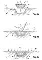
- a mold 8 whose surface 81 has the general shape desired for the skin 2 and which comprises at least one recessed shape 82 corresponding to the impression of the at least one stiffener 3a, 3b which must be performed on one side of the skin located on the side of the mold 8 during the production of the panel.
- fibers 31, for example pre-impregnated fibers, having to constitute the at least one stiffener are deposited in the recessed form 82.
- the fibers 31 are generally deposited in the recessed form 82 in the form of preforms previously produced by processes known and not shown, for example by means of draper machines which deposit on the media of suitable shapes the fibers by locks or successive folds in the form of more or less wide strips and more or less long, respecting the orientation of fibers and the number of folds expected.
- the core 5 produced as previously described is placed in the recessed form 82 so that the fibers 31 deposited are found between the mold 8 and the core 5.
- the fibers 11 of the skin are deposited on the surface 81 of the mold 8 and cover on the one hand the fibers 32, 33, deposited to form a sole of the at least one stiffener, in the contact zones between the at least one stiffener 3a, 3b and on the other hand the skin 2 and on the other hand the core 5.
- the core 5 Because of its rigidity obtained in particular by the compacted granular solid material 53 contained in the bladder, the core 5 is able to undergo the forces F exerted by the means, schematized by a deposition head 15, of depositing the folds of fibers 11 of the skin, efforts which are generally necessary to obtain compacted fibers to each other, a necessary condition for obtaining a good placement of the folds, a good orientation of the fibers and good health of the finished composite material.
- the correct placement of the fibers is also obtained by choosing a core which takes into account the dimensions of the location filled by said core at the time of deposition of the fibers and is capable of reconstituting the surface on which the fibers of the skin are deposited. 2 without significant deformation.
- a pressure Pa is applied to the surface of the deposited fibers 11 opposite to the surface in contact with the mold 8 and, in a known manner, the temperature is increased according to a determined cycle to cause the hardening of the resin which impregnates the fibers.
- This pressure Pa or autoclave pressure is for example obtained by means of a bladder 85 which covers the fibers deposited on the mold and which is subjected to an external pressure possibly completed by a depression of the space between the outer bladder 85 and the mold 8, that is to say the space in which the fibers 11 are located.
- an external pressure possibly completed by a depression of the space between the outer bladder 85 and the mold 8, that is to say the space in which the fibers 11 are located.
- the pressure Pn of the intergranular fluid contained in the bladder 51 is increased to a value able to compensate for the autoclave pressure Pa exerted through the walls of the bladder 85 and to avoid deformation local skin 2.
- This increase in the pressure Pn in the bladder 51 has the effect of correcting the volume of the core 5, the dimensions of which have preferably been chosen to take account of the expansion of the uncured composite material and its decrease in thickness during its hardening. under the effect of applied pressures.
- One way to achieve the pressure increase Pn is to connect the inner volume of the bladder 51 containing the intergranular fluid 59 to the autoclave pressure generating means to increase the pressure Pn in the bladder at the same time as the pressure. Pa autoclave is increased.
- the pressure Pn of the intergranular fluid can be chosen equal to the autoclave pressure Pa .
- the stiffener core bladders 51 have, in accordance with the characteristics of the stiffeners, relatively small sections.
- the characteristic dimensions of the recessed areas of the bladder, in particular the width I 1 are substantially smaller than those of the corresponding outer sections, the width Ie , because of the thickness of the elastomer bladder which is more negligible compared to the other dimensions of the sections. Due to this substantial difference in inner and outer dimensions of the core bladder, the pressure on the outer surface generated by the pressure Pn in the bladder is lower than the internal pressure Pn , and therefore is lower than the pressure Pa if the internal volume of the bladder is subjected to autoclave pressure.
- the pressure Pn applied inside the bladder 51 to compensate for the forces due to the autoclave pressure Pa will be corrected to take account of this effect.
- a multiplier coefficient taking into account the thickness of the bladder 51 is applied to the pressure of autoclave Pa to obtain a value of the pressure Pn in the core which restores an apparent pressure substantially equal to Pa on the outer face of the core subjected to autoclave pressure.
- the pressure in the core is preferably slaved to the desired value when the autoclave pressure is applied.
- the pressure in the core is advantageously obtained automatically by connecting the internal volume of the core bladder to the autoclave pressure by means of a piston pressure multiplier.
- the pressure Pn also has the effect of compressing the fibers of the web 35, 36, 37 of the stiffener on the corresponding surfaces 84, 85 of the cavity 82 in the mold 8, which is only partially achieved by the forces that the autoclave pressure Pa exerts on the core 5 which bears on the inclined cores of the stiffeners, and is not achieved if the surfaces 85 of the cavity against which the webs of the stiffeners are supported are close to normal to the surface skin 2.
- the core 5 is then emptied of the granular solid material 53 it contains through the opening 52, at least partially, so that the bladder 51 becomes sufficiently deformable to be removed by an accessible end of the stiffener.
- a depression is created in the bladder 51 emptied granular solid material which has the effect of causing a crushing of said bladder under the effect of atmospheric pressure which facilitates the separation of the walls 55, 56, 57 of the bladder surfaces of the hollow form 4a, 4b of the stiffener and which facilitates the extraction of the bladder.
- the choice of a granular solid material 53 having a suitable coefficient of thermal expansion is essential because, if the expansion in the direction of the width lr and the height hr of the core 5 is negligible because of the relatively small clearance dimensions, the expansion becomes critical over the length Lr of the core.
- an economical and relatively light material such as aluminum, with an expansion coefficient of 24 10E-6 per Kelvin, used to fill an induced bladder, during a heat treatment in which the temperature is increased by 200 Kelvin, an elongation of the core of the order of 5 mm per meter.
- Such elongation is totally incompatible with the production of a piece of composite material of dimensions up to several meters while respecting the qualities required for an aeronautical structure.
- the granular solid material 53 is therefore advantageously selected from materials whose expansion coefficient is closest to the coefficient of expansion of the composite material used to produce the stiffened panel.
- Composite materials generally have a low coefficient of thermal expansion, of the order of 3 to 10E-6 per Kelvin.
- the composite material of the stiffened panel 1 and the core 5 expand and contract together with variations in temperature which avoids introducing unwanted deformations and residual stresses into the panel.
- the method described for making a composite stiffened panel from prepreg fibers deposited on a mold having a shape is easily adapted to other methods of making parts of composite material.
- the pressure exerted by means of an outer bladder 85 and an autoclave pressure Pa is in certain cases carried out by a counterform which can be rigid or be made at least partly with an elastomer.
- a counterform which can be rigid or be made at least partly with an elastomer.
- the pressure Pn in the core is increased during the curing phase of the resin to a value close to the desired pressure to apply the counterform in the process.
- the fibers are deposited dry, that is to say without having been pre-impregnated with a resin, in a mold, generally a form and a counterform that are assembled when the fibers are in place, and the resin is injected into the mold whose walls precisely determine the shapes of the panel.
- the pressure Pn in the bladder 51 is preferably chosen to be at least equal to the pressure of the resin in the mold or greater depending on the desired compression for the fibers in the area of the stiffener.
- the method according to the invention described for a stiffener said ⁇ is applicable to other forms of stiffener because on the one hand the dimensional stability problems of the core that solves the invention are always critical and the generation of a counterpressure in the core to counter the pressure exerted on the skin is still necessary to ensure the quality of the composite material in the area of the stiffener, even if the skin 2 is directly in contact with the core 5 as in the example of the stiffeners of the Figures 6b and 6c .
- the realization of a core having the shape adapted to the volume to be filled during the production of the part allows the implementation of the method.
- the process is advantageously applied even when the recessed shapes are not completely or not at all closed because the rigid or elastomeric cores do not make it possible to apply a counter-pressure able to avoid a local deformation of the skin or the stiffener and because the extraction of the core without damaging the panel can be made difficult even impossible because of the sectional variations of the stiffeners on the long lengths and or particular shapes of the stiffener, for example a twisting linked to a curvature of the panel, and or variations in the thickness of the skin.
- the pressure Pn inside the bladder makes it possible to create a perfectly controlled pressure on the webs 36, 37, 38 of the stiffeners which, close to the normal to the local surface of the skin, are not compressed by the pressure autoclave or counter-mold.
- the core according to the invention is extracted once emptied of the solid granular material by the longitudinal side opening if such an opening is accessible.
- the method can also be applied when the at least one stiffener is made of hardened composite material before being deposited in the cavity 82 of the mold 8.
- the at least one stiffener can be made in a first step by any method implementation of the composite materials, which may be different from that which will be used to form the skin of the stiffened panel and which may be different depending on the stiffener when two or more stiffeners are used for the realization of the stiffened panel.
- a stiffener can be made by curing preimpregnated fibers in a mold but also for example by a RTM resin transfer method or by pultrusion or by forming. In this case the at least one stiffener is deposited in the cavity 82, the core 5 is deposited in the portion of the mold 8 to remain recessed and the skin is deposited as already described.
- the at least one stiffener may also be formed with fibers in the cavity 82 of the mold, the core set up and a skin made of material previously hardened reported on the mold.
- the at least one stiffener and the skin may also both be previously made of hardened material and assembled by gluing in the mold 8 by applying the method, an adhesive being deposited on the surfaces of the stiffener and or panel to be assembled.
- the core is particularly useful for preventing deformation of the skin and the stiffener during the application of the pressures associated with bonding, deformations which introduce unwanted residual stresses in the composite material, see permanent deformations of the stiffened panel.
- the method also makes it possible to produce panels comprising stiffeners on their two faces, the order in which the fibers of the skin are deposited, the fibers of the stiffeners and the cores are then determined by the method used for forming the panel stiffened.
Landscapes
- Engineering & Computer Science (AREA)
- Mechanical Engineering (AREA)
- Chemical & Material Sciences (AREA)
- Composite Materials (AREA)
- Manufacturing & Machinery (AREA)
- Aviation & Aerospace Engineering (AREA)
- Architecture (AREA)
- Civil Engineering (AREA)
- Structural Engineering (AREA)
- Casting Or Compression Moulding Of Plastics Or The Like (AREA)
- Moulding By Coating Moulds (AREA)
- Moulds For Moulding Plastics Or The Like (AREA)
- Laminated Bodies (AREA)
Claims (12)
- Verfahren zur Herstellung einer versteiften Platte (1) aus Verbundmaterial, wobei die besagte Platte eine Hülle (2) und zumindest eine Versteifung (3a, 3b) enthält, und das besagte Verbundmaterial aus Fasern besteht, die von einem Harz umhüllt sind, das im Laufe einer Aushärtungsphase von einem zähflüssigen oder flüssigen Zustand in einen festen Zustand übergeht, wobei die besagte versteifte Platte (1) zumindest eine langgestreckte hohle Form (4a, 4b) enthält, bei der eine der Abmessungen, die Länge, gegenüber den anderen Abmessungen, die in etwa orthogonal zur Länge liegen, groß ist, und die durch die Oberflächen von zumindest einer Versteifung und der Hülle gebildet wird, wobei bei diesem Verfahren:- zumindest eine Versteifung (3a, 3b) oder eine Preform der besagten Versteifung in einer hohlen Abformung (82) einer Oberfläche (81) einer Form (8) angeordnet ist, die die Form der Hülle (2) der herzustellenden versteiften Platte aufweist;- ein Kern (5), der ein Volumen bildet, das vollkommen oder teilweise zumindest einer hohlen Form (4a, 4b) entspricht, so in der hohlen Abformung angebracht ist, dass sich die Versteifung oder ihre Preform zwischen der Form (8) und dem Kern (5) befindet, wobei der besagte Kern eine Blase (51) aus flexiblem Material enthält, die eine Außenfläche aufweist, die ein Volumen des Kerns (5) abgrenzt, dessen Formen und Abmessungen mit dem Volumen der hohlen Form übereinstimmen, und mit einer Innenfläche, die ein Volumen der Blase (51) bildet, wobei dieses Volumen mit einem festen körnigen Material (53) gefüllt ist;- das Material (11), das dazu bestimmt ist, die Hülle (2) der versteiften Platte zu bilden, so auf der Oberfläche (81) der Form (8) aufgebracht wird, dass es die besagte Oberfläche, die Sohlen (32, 33) der Versteifung und eine Oberfläche des Kerns (5) zwischen den besagten Schlen bedeckt;
dadurch gekennzeichnet, dass:- das feste körnige Material (53) unter jenen Materialien ausgesucht wird, die einen Wärmeausdehnungskoeffizienten aufweisen, der in etwa gleich dem Wärmeausdehnungskoeffizienten des Verbundmaterials ist, das zur Herstellung der versteiften Platte (1) verwendet wird, und;- ein Druck Pn einer intergranularen Flüssigkeit (59), die in der Blase (51) enthalten ist, während der Aushärtungsphase des Harzes so angehoben wird, dass der im Kern vorherrschende Druck Pn in etwa jene Kräfte ausgleicht, die von den Druckvorrichtungen Pa des Verbundmaterials auf die Oberfläche der Form (8) ausgeübt werden, und dass das Volumen des Kerns (5) verändert wird, um die Verringerung der Verbundmaterialdicke während der Aushärtungsphase auszugleichen. - Verfahren nach Anspruch 1, bei dem der Kern (5) anhand von Abschnitten gefertigt wird, deren Abmessungen in etwa unter den Abmessungen der hohlen Form (4a, 4b) der versteiften Platte (1) liegen.
- Verfahren nach Anspruch 2, bei dem die Abmessungen des Kernabschnitts (5) jenen Abmessungen der hohlen Form entsprechen, die von dem besagten Kern vor der Aushärtungsphase des Verbundmaterials einzunehmen sind.
- Verfahren nach einem der vorherigen Ansprüche, bei dem das feste körnige Material (53) ein Material oder eine Materialmischung ist, deren Wärmeausdehnungskoeffizienten zwischen 3 10E-6 Kelvin und 9 10E-6 Kelvin liegen
- Verfahren nach Anspruch 4, bei dem das feste körnige Material (53) Borosilikatglas ist.
- Verfahren nach Anspruch 4, bei dem das feste körnige Material (53) eine Eisen-Nickel-Legierung vom Typ Invar mit einem geringen Wärmeausdehnungskoeffizienten ist.
- Verfahren nach einem der vorherigen Ansprüche, bei dem der Druck Pn der in der Blase (51) enthaltenen intergranularen Flüssigkeit (59) im Laufe eines Vorbereitungsschrittes des Kernes (5) so gesenkt wird, dass die Wände der Blase (51) das feste körnige Material (53) unter Einwirkung der Stauchkräfte der Blase verdichten, die mit einem Druck zusammenhängen, der auf die Außenfläche der Blase aus flexiblem Material ausgeübt wird, um dem Kern eine stabile Form zu verleihen.
- Verfahren nach einem der vorherigen Ansprüche, bei dem die Druckvorrichtungen des Verbundmaterials eine äußere Blase (85) enthalten, die einem Autoklav-Druck Pa unterworfen ist, und bei dem der Druck Pn auf einen Wert erhöht wird, der in etwa dem Wert Pa entspricht.
- Verfahren nach Anspruch 8, bei dem die intergranulare Flüssigkeit einem Autoklav-Druck Par unterworfen wird, sodass Pn in etwa dem Wert Pa entspricht.
- Verfahren nach Anspruch 9, bei dem der Druck Pn der intergranularen Flüssigkeit dem korrigierten Autoklav-Druck Pa entspricht, um den Unterschied zwischen der Außenfläche des Kerns, der dem Autoklav-Druck unterworfen ist, und der Innenfläche der Blase (51) auszugleichen, die dem Druck der intergranularen Flüssigkeit gegenüber der besagten Außenfläche unterworfen ist, die dem Autoklav-Druck unterliegt.
- Verfahren nach einem der vorherigen Ansprüche, bei dem das Harz durch eine Wärmebehandlung ausgehärtet wird, und dessen Kern (5) mit einem festen körnigen Material (53) und/ oder einer interstitiellen Flüssigkeit (59) ausgefüllt ist, die entsprechend einem Wärmeausdehnungskoeffizienten ausgewählt wird, der in der Lage ist, für eine Wärmeverbreitung und eine gleichförmige Temperatur während der Wärmebehandlung zu sorgen.
- Verfahren nach einem der vorherigen Ansprüche, bei dem der Druck Pn in der Blase (51) des Kerns (5) nach dem zumindest teilweisen Entleeren des festen körnigen Materials (53) auf einen Wert unter jenem des atmosphärischen Drucks verringert wird.
Applications Claiming Priority (2)
| Application Number | Priority Date | Filing Date | Title |
|---|---|---|---|
| FR0650957A FR2898539B1 (fr) | 2006-03-20 | 2006-03-20 | Procede de realisation de panneaux raidis en materiau composite et panneaux ainsi realises |
| PCT/EP2007/052622 WO2007107553A1 (fr) | 2006-03-20 | 2007-03-20 | Procede de realisation de panneaux raidis en materiau composites et panneaux ainsi realises |
Publications (2)
| Publication Number | Publication Date |
|---|---|
| EP2004390A1 EP2004390A1 (de) | 2008-12-24 |
| EP2004390B1 true EP2004390B1 (de) | 2011-03-02 |
Family
ID=37507713
Family Applications (1)
| Application Number | Title | Priority Date | Filing Date |
|---|---|---|---|
| EP07727099A Not-in-force EP2004390B1 (de) | 2006-03-20 | 2007-03-20 | Verfahren zur herstellung versteifter platten aus verbundwerkstoff |
Country Status (10)
| Country | Link |
|---|---|
| US (1) | US20090309264A1 (de) |
| EP (1) | EP2004390B1 (de) |
| CN (1) | CN101448631A (de) |
| AT (1) | ATE500052T1 (de) |
| CA (1) | CA2649621A1 (de) |
| DE (1) | DE602007012844D1 (de) |
| ES (1) | ES2360832T3 (de) |
| FR (1) | FR2898539B1 (de) |
| RU (1) | RU2426646C2 (de) |
| WO (1) | WO2007107553A1 (de) |
Families Citing this family (39)
| Publication number | Priority date | Publication date | Assignee | Title |
|---|---|---|---|---|
| US8601694B2 (en) † | 2008-06-13 | 2013-12-10 | The Boeing Company | Method for forming and installing stringers |
| DE102006031325B4 (de) | 2006-07-06 | 2010-07-01 | Airbus Deutschland Gmbh | Verfahren zur Herstellung eines Faserverbundbauteils für die Luft- und Raumfahrt |
| DE102006031334A1 (de) | 2006-07-06 | 2008-01-10 | Airbus Deutschland Gmbh | Verfahren zur Herstellung eines Faserverbundbauteils für die Luft- und Raumfahrt |
| DE102006031335B4 (de) | 2006-07-06 | 2011-01-27 | Airbus Operations Gmbh | Verfahren zur Herstellung eines Faserverbundbauteils für die Luft- und Raumfahrt |
| DE102006031336B4 (de) | 2006-07-06 | 2010-08-05 | Airbus Deutschland Gmbh | Verfahren zur Herstellung eines Faserverbundbauteils in der Luft- und Raumfahrt |
| FR2924375B1 (fr) | 2007-11-30 | 2013-05-10 | Eads Europ Aeronautic Defence | Procede de realisation d'un noyau de moulage et noyau de moulage pour la fabrication d'une piece complexe en materiau compositie |
| ES2351594T3 (es) | 2007-12-06 | 2011-02-08 | Saab Ab | Procedimiento y aparato para la fabricación de un artículo que incluye un espacio vacío. |
| FR2928577B1 (fr) | 2008-03-14 | 2011-11-25 | Airbus France | Procede de realisation d'un raidisseur evide en forme de omega et noyau pour la realisation d'un raidisseur evide en forme de omega |
| JP5416554B2 (ja) * | 2009-11-06 | 2014-02-12 | 川崎重工業株式会社 | 複合材料構造物製造用治具 |
| DE102010008711A1 (de) * | 2010-02-19 | 2011-08-25 | GKN Aerospace Services Limited, Isle of Wight | Verfahren und Anordnung zur Herstellung eines einstückigen Hohlprofilbauteils mit Faserverbundwerkstoff |
| GB2485183A (en) * | 2010-11-04 | 2012-05-09 | Rolls Royce Plc | Generating residual stress in hollow body during cure to deflect composite body on relaxation |
| GB201020152D0 (en) * | 2010-11-29 | 2011-01-12 | Airbus Uk Ltd | Aircraft panel structure and aircraft panel structure manufacturing method for alleviation of stress |
| FR2995279B1 (fr) * | 2012-09-10 | 2017-05-26 | European Aeronautic Defence & Space Co Eads France | Panneau raidi |
| US8986484B2 (en) | 2012-10-10 | 2015-03-24 | The Boeing Company | Shape-distorting tooling system and method for curing composite parts |
| FR2998545B1 (fr) * | 2012-11-23 | 2016-10-28 | Airbus Operations Sas | Nacelle d'aeronef comprenant une liaison renforcee entre une entree d'air et une motorisation |
| CN104057648A (zh) * | 2013-03-18 | 2014-09-24 | 空客(北京)工程技术中心有限公司 | 混合夹层结构、加强件及其加工方法 |
| CN103195446A (zh) * | 2013-04-19 | 2013-07-10 | 山东科技大学 | 软岩巷道底臌让压缓冲装置及其施工方法 |
| US9205634B2 (en) * | 2013-05-16 | 2015-12-08 | The Boeing Company | Composite structure and method |
| EP3052305B1 (de) * | 2013-10-04 | 2018-09-19 | United Technologies Corporation | Flexibles harztransferformwerkzeug |
| EP2865516B1 (de) | 2013-10-28 | 2016-03-09 | AIRBUS HELICOPTERS DEUTSCHLAND GmbH | Oberflächeversteifte Verbundplatte und Verfahren zu deren Herstellung |
| DE102014215965A1 (de) | 2014-08-12 | 2016-02-18 | Bayerische Motoren Werke Aktiengesellschaft | Verfahren zur Herstellung eines faserverstärkten Kunststoffbauteils |
| DE102015122211A1 (de) * | 2015-06-26 | 2016-12-29 | Grob Aircraft Ag | Werkzeug |
| TWI613065B (zh) * | 2015-12-08 | 2018-02-01 | National Chung Shan Institute Of Science And Technology Armaments Bureau | 一種樑肋與蒙皮一體成形之模具結構及其製作方法 |
| US20170232688A1 (en) * | 2016-02-15 | 2017-08-17 | General Electric Company | Incorporation Of Jamming Technologies In Tooling For Composites Processing |
| CN106273539A (zh) * | 2016-08-29 | 2017-01-04 | 中航复合材料有限责任公司 | 一种帽型加筋壁板共固化成型工艺方法 |
| CN106314753A (zh) * | 2016-09-23 | 2017-01-11 | 江西洪都航空工业集团有限责任公司 | 一种高强度高刚度轻质整体机体结构 |
| US10899103B2 (en) | 2016-11-03 | 2021-01-26 | Anthony A. DUPont | Isogrid stiffening elements |
| US10639855B2 (en) * | 2017-02-07 | 2020-05-05 | General Electric Company | Applicator systems for applying pressure to a structure |
| CN106933098B (zh) * | 2017-02-24 | 2019-10-01 | 上海理工大学 | 平板型机械结构热变形补偿系统设计方法 |
| EP3659774B1 (de) * | 2017-07-25 | 2023-05-31 | Subaru Corporation | Verbundstoffmaterialformgestell und verbundstoffmaterialformverfahren |
| US10717239B2 (en) * | 2017-09-28 | 2020-07-21 | The Boeing Company | Fabrication of gap fillers for composite parts that exhibit varying radii of curvature |
| CN108639310B (zh) * | 2018-06-15 | 2021-10-15 | 大连理工大学 | 一种基于充压变刚度弧形管驱动的可变形板结构 |
| CN109228375B (zh) * | 2018-11-01 | 2023-08-18 | 成都纵横大鹏无人机科技有限公司 | 一种蒙皮成型方法 |
| RU2764456C1 (ru) * | 2019-03-08 | 2022-01-17 | АйЭйчАй АЭРОСПЕЙС КО., ЛТД. | Система и способ формовки frp |
| DE102019005910A1 (de) * | 2019-08-22 | 2021-02-25 | Siempelkamp Maschinen- Und Anlagenbau Gmbh | Verfahren und Vorrichtung zum Erzeugen eines Bauelements |
| CN110524910A (zh) * | 2019-09-09 | 2019-12-03 | 山东非金属材料研究所 | 一种vartm工艺用复合材料模具及其制造方法 |
| US20210308967A1 (en) * | 2020-04-07 | 2021-10-07 | Rohr, Inc. | Hybrid mandrel for use in tooling methods and the manufacture of thrust reverser cascades and structures susceptible to trapped tooling |
| DE102020134901A1 (de) * | 2020-12-23 | 2022-06-23 | Airbus Operations Gmbh | Formkern zur Herstellung eines Bauteils aus Faserverbundmaterial |
| CN115258128B (zh) * | 2022-09-27 | 2022-12-02 | 成都市鸿侠科技有限责任公司 | 用于飞机壁板加工的加固结构 |
Family Cites Families (12)
| Publication number | Priority date | Publication date | Assignee | Title |
|---|---|---|---|---|
| US4783232A (en) * | 1983-09-02 | 1988-11-08 | Allied-Signal Inc. | Filament winding using a rotationally molded inner layer |
| IT1223923B (it) * | 1988-11-22 | 1990-09-29 | Ferrari Engineering Spa | Procedimento per la costruzione di elementi monolitici cavi in materiale composito in particolare in fibra di carbonio |
| SU1777297A1 (ru) * | 1990-02-12 | 1997-05-20 | Обнинское научно-производственное объединение "Технология" | Панель из композиционного материала и способ ее изготовления |
| US5262121A (en) * | 1991-12-18 | 1993-11-16 | Goodno Kenneth T | Method of making and using flexible mandrel |
| US5387098A (en) * | 1992-04-23 | 1995-02-07 | The Boeing Company | Flexible reusable mandrels |
| AU1194595A (en) * | 1993-11-26 | 1995-06-13 | Alan Roger Harper | Casting method and apparatus and products thereof |
| GB2292332B (en) * | 1994-04-22 | 1999-04-28 | Alan Roger Harper | Moulding process and apparatus therefor |
| US5968445A (en) * | 1998-01-05 | 1999-10-19 | The Boeing Company | Method and apparatus for curing large composite panels |
| US6458309B1 (en) * | 1998-06-01 | 2002-10-01 | Rohr, Inc. | Method for fabricating an advanced composite aerostructure article having an integral co-cured fly away hollow mandrel |
| US7559332B2 (en) * | 2002-07-02 | 2009-07-14 | Toyota Motor Sales U.S.A., Inc. | Media removal apparatus and methods of removing media |
| RU2242369C1 (ru) * | 2003-05-19 | 2004-12-20 | Федеральное государственное унитарное предприятие "Обнинское научно-производственное предприятие "Технология" | Опорный узел трехслойной панели |
| US7293737B2 (en) * | 2004-04-20 | 2007-11-13 | The Boeing Company | Co-cured stringers and associated mandrel and fabrication method |
-
2006
- 2006-03-20 FR FR0650957A patent/FR2898539B1/fr not_active Expired - Fee Related
-
2007
- 2007-03-20 WO PCT/EP2007/052622 patent/WO2007107553A1/fr not_active Ceased
- 2007-03-20 EP EP07727099A patent/EP2004390B1/de not_active Not-in-force
- 2007-03-20 CN CNA2007800181202A patent/CN101448631A/zh active Pending
- 2007-03-20 RU RU2008141301/05A patent/RU2426646C2/ru not_active IP Right Cessation
- 2007-03-20 US US12/298,104 patent/US20090309264A1/en not_active Abandoned
- 2007-03-20 DE DE602007012844T patent/DE602007012844D1/de active Active
- 2007-03-20 ES ES07727099T patent/ES2360832T3/es active Active
- 2007-03-20 AT AT07727099T patent/ATE500052T1/de not_active IP Right Cessation
- 2007-03-20 CA CA002649621A patent/CA2649621A1/fr not_active Abandoned
Also Published As
| Publication number | Publication date |
|---|---|
| ES2360832T3 (es) | 2011-06-09 |
| DE602007012844D1 (de) | 2011-04-14 |
| CA2649621A1 (fr) | 2007-09-27 |
| CN101448631A (zh) | 2009-06-03 |
| RU2426646C2 (ru) | 2011-08-20 |
| RU2008141301A (ru) | 2010-04-27 |
| EP2004390A1 (de) | 2008-12-24 |
| ATE500052T1 (de) | 2011-03-15 |
| WO2007107553A1 (fr) | 2007-09-27 |
| FR2898539A1 (fr) | 2007-09-21 |
| FR2898539B1 (fr) | 2008-05-23 |
| US20090309264A1 (en) | 2009-12-17 |
Similar Documents
| Publication | Publication Date | Title |
|---|---|---|
| EP2004390B1 (de) | Verfahren zur herstellung versteifter platten aus verbundwerkstoff | |
| EP1996390B1 (de) | Verfahren zur herstellung von strukturen komplexer formen aus verbundmaterialien | |
| CA2930813C (fr) | Procede d'impregnation d'une preforme fibreuse et dispositif pour la mise en oeuvre de ce procede | |
| EP2560808B1 (de) | Vorrichtung zur herstellung eines gehäuses aus verbundstoff und herstellungsverfahren mit einer derartigen vorrichtung | |
| WO1998039151A1 (fr) | Procede de fabrication de pieces creuses en materiau composite | |
| FR3118723A1 (fr) | Procédés et dispositifs de formage de matériaux composites | |
| CA2232097C (fr) | Procede de realisation de pieces creuses de precision en materiau composite | |
| EP2219840B1 (de) | Verfahren zur herstellung eines formkerns zur herstellung eines komplexen teils aus einem verbundmaterial | |
| EP3423267B1 (de) | Verfahren und vorrichtung zur herstellung eines hohlen teils aus einem verbundwerkstoff und nach diesem verfahren hergestellte turbinenschaufel | |
| EP3877161B1 (de) | Aushärtform zur herstellung einer aus verbundstoffmaterial aus einer vorform gefertigten turbomaschinenkomponente und verfahren zur fertigung einer komponente mittels solch einer form | |
| FR3081761A1 (fr) | Procede de fabrication d'une piece en matiere composite | |
| FR3061070A1 (fr) | Procede de realisation d’un panneau auto raidi en materiaux composites et panneau obtenu par ledit procede | |
| WO2018220337A1 (fr) | Procede de demoulage d'un matériau composite à matrice organique | |
| EP3536489B1 (de) | Herstellungssystem und -verfahren von thermoplastischen strukturteilen | |
| EP4227077B1 (de) | Form für gebogenes paneel | |
| FR3063674A1 (fr) | Dispositif d'application de pression mecanique, procede d'impregnation et procede de collage | |
| FR3156370A1 (fr) | Procédé de fabrication d’une pièce en matériaux composites creuse comprenant des raidisseurs internes | |
| FR3162015A1 (fr) | Outillage de fabrication d’une piece aeronautique et un procede de fabrication de la piece aeronautique au moyen de cet outillage | |
| EP4689472A1 (de) | Verfahren zur herstellung eines tanks aus verbundmaterial | |
| FR3146087A1 (fr) | Procédé et outil de moulage pour la fabrication d’un composant en plastique | |
| FR3159550A1 (fr) | Dispositif pour le préformage d’un profilé composite creux et procédé de préformage d’un profilé composite creux, notamment de type raidisseur composite | |
| FR2999469A1 (fr) | Procede de fabrication de pieces en materiau composite a ame a cellule ouverte |
Legal Events
| Date | Code | Title | Description |
|---|---|---|---|
| PUAI | Public reference made under article 153(3) epc to a published international application that has entered the european phase |
Free format text: ORIGINAL CODE: 0009012 |
|
| 17P | Request for examination filed |
Effective date: 20081013 |
|
| AK | Designated contracting states |
Kind code of ref document: A1 Designated state(s): AT BE BG CH CY CZ DE DK EE ES FI FR GB GR HU IE IS IT LI LT LU LV MC MT NL PL PT RO SE SI SK TR |
|
| 17Q | First examination report despatched |
Effective date: 20090612 |
|
| GRAP | Despatch of communication of intention to grant a patent |
Free format text: ORIGINAL CODE: EPIDOSNIGR1 |
|
| RIC1 | Information provided on ipc code assigned before grant |
Ipc: B29C 70/44 20060101ALI20100803BHEP Ipc: B29D 99/00 20100101AFI20100803BHEP |
|
| RTI1 | Title (correction) |
Free format text: METHOD OF PRODUCING STIFFENED PANELS MADE OF A COMPOSITE |
|
| GRAS | Grant fee paid |
Free format text: ORIGINAL CODE: EPIDOSNIGR3 |
|
| GRAA | (expected) grant |
Free format text: ORIGINAL CODE: 0009210 |
|
| AK | Designated contracting states |
Kind code of ref document: B1 Designated state(s): AT BE BG CH CY CZ DE DK EE ES FI FR GB GR HU IE IS IT LI LT LU LV MC MT NL PL PT RO SE SI SK TR |
|
| REG | Reference to a national code |
Ref country code: GB Ref legal event code: FG4D Free format text: NOT ENGLISH |
|
| REG | Reference to a national code |
Ref country code: CH Ref legal event code: EP |
|
| REG | Reference to a national code |
Ref country code: IE Ref legal event code: FG4D Free format text: LANGUAGE OF EP DOCUMENT: FRENCH |
|
| REF | Corresponds to: |
Ref document number: 602007012844 Country of ref document: DE Date of ref document: 20110414 Kind code of ref document: P |
|
| REG | Reference to a national code |
Ref country code: DE Ref legal event code: R096 Ref document number: 602007012844 Country of ref document: DE Effective date: 20110414 |
|
| REG | Reference to a national code |
Ref country code: SE Ref legal event code: TRGR |
|
| REG | Reference to a national code |
Ref country code: ES Ref legal event code: FG2A Ref document number: 2360832 Country of ref document: ES Kind code of ref document: T3 Effective date: 20110609 |
|
| REG | Reference to a national code |
Ref country code: NL Ref legal event code: VDEP Effective date: 20110302 |
|
| PG25 | Lapsed in a contracting state [announced via postgrant information from national office to epo] |
Ref country code: LV Free format text: LAPSE BECAUSE OF FAILURE TO SUBMIT A TRANSLATION OF THE DESCRIPTION OR TO PAY THE FEE WITHIN THE PRESCRIBED TIME-LIMIT Effective date: 20110302 Ref country code: LT Free format text: LAPSE BECAUSE OF FAILURE TO SUBMIT A TRANSLATION OF THE DESCRIPTION OR TO PAY THE FEE WITHIN THE PRESCRIBED TIME-LIMIT Effective date: 20110302 Ref country code: GR Free format text: LAPSE BECAUSE OF FAILURE TO SUBMIT A TRANSLATION OF THE DESCRIPTION OR TO PAY THE FEE WITHIN THE PRESCRIBED TIME-LIMIT Effective date: 20110603 |
|
| LTIE | Lt: invalidation of european patent or patent extension |
Effective date: 20110302 |
|
| PG25 | Lapsed in a contracting state [announced via postgrant information from national office to epo] |
Ref country code: FI Free format text: LAPSE BECAUSE OF FAILURE TO SUBMIT A TRANSLATION OF THE DESCRIPTION OR TO PAY THE FEE WITHIN THE PRESCRIBED TIME-LIMIT Effective date: 20110302 Ref country code: AT Free format text: LAPSE BECAUSE OF FAILURE TO SUBMIT A TRANSLATION OF THE DESCRIPTION OR TO PAY THE FEE WITHIN THE PRESCRIBED TIME-LIMIT Effective date: 20110302 Ref country code: BG Free format text: LAPSE BECAUSE OF FAILURE TO SUBMIT A TRANSLATION OF THE DESCRIPTION OR TO PAY THE FEE WITHIN THE PRESCRIBED TIME-LIMIT Effective date: 20110602 Ref country code: NL Free format text: LAPSE BECAUSE OF FAILURE TO SUBMIT A TRANSLATION OF THE DESCRIPTION OR TO PAY THE FEE WITHIN THE PRESCRIBED TIME-LIMIT Effective date: 20110302 Ref country code: CY Free format text: LAPSE BECAUSE OF FAILURE TO SUBMIT A TRANSLATION OF THE DESCRIPTION OR TO PAY THE FEE WITHIN THE PRESCRIBED TIME-LIMIT Effective date: 20110302 Ref country code: SI Free format text: LAPSE BECAUSE OF FAILURE TO SUBMIT A TRANSLATION OF THE DESCRIPTION OR TO PAY THE FEE WITHIN THE PRESCRIBED TIME-LIMIT Effective date: 20110302 |
|
| REG | Reference to a national code |
Ref country code: IE Ref legal event code: FD4D |
|
| BERE | Be: lapsed |
Owner name: EUROPEAN AERONAUTIC DEFENCE AND SPACE COMPANY EAD Effective date: 20110331 |
|
| PG25 | Lapsed in a contracting state [announced via postgrant information from national office to epo] |
Ref country code: EE Free format text: LAPSE BECAUSE OF FAILURE TO SUBMIT A TRANSLATION OF THE DESCRIPTION OR TO PAY THE FEE WITHIN THE PRESCRIBED TIME-LIMIT Effective date: 20110302 Ref country code: PT Free format text: LAPSE BECAUSE OF FAILURE TO SUBMIT A TRANSLATION OF THE DESCRIPTION OR TO PAY THE FEE WITHIN THE PRESCRIBED TIME-LIMIT Effective date: 20110704 Ref country code: IE Free format text: LAPSE BECAUSE OF FAILURE TO SUBMIT A TRANSLATION OF THE DESCRIPTION OR TO PAY THE FEE WITHIN THE PRESCRIBED TIME-LIMIT Effective date: 20110302 Ref country code: MC Free format text: LAPSE BECAUSE OF NON-PAYMENT OF DUE FEES Effective date: 20110331 |
|
| REG | Reference to a national code |
Ref country code: CH Ref legal event code: PL |
|
| PG25 | Lapsed in a contracting state [announced via postgrant information from national office to epo] |
Ref country code: RO Free format text: LAPSE BECAUSE OF FAILURE TO SUBMIT A TRANSLATION OF THE DESCRIPTION OR TO PAY THE FEE WITHIN THE PRESCRIBED TIME-LIMIT Effective date: 20110302 Ref country code: SK Free format text: LAPSE BECAUSE OF FAILURE TO SUBMIT A TRANSLATION OF THE DESCRIPTION OR TO PAY THE FEE WITHIN THE PRESCRIBED TIME-LIMIT Effective date: 20110302 Ref country code: IS Free format text: LAPSE BECAUSE OF FAILURE TO SUBMIT A TRANSLATION OF THE DESCRIPTION OR TO PAY THE FEE WITHIN THE PRESCRIBED TIME-LIMIT Effective date: 20110702 Ref country code: CZ Free format text: LAPSE BECAUSE OF FAILURE TO SUBMIT A TRANSLATION OF THE DESCRIPTION OR TO PAY THE FEE WITHIN THE PRESCRIBED TIME-LIMIT Effective date: 20110302 |
|
| PG25 | Lapsed in a contracting state [announced via postgrant information from national office to epo] |
Ref country code: MT Free format text: LAPSE BECAUSE OF FAILURE TO SUBMIT A TRANSLATION OF THE DESCRIPTION OR TO PAY THE FEE WITHIN THE PRESCRIBED TIME-LIMIT Effective date: 20110302 Ref country code: BE Free format text: LAPSE BECAUSE OF NON-PAYMENT OF DUE FEES Effective date: 20110331 |
|
| PLBE | No opposition filed within time limit |
Free format text: ORIGINAL CODE: 0009261 |
|
| STAA | Information on the status of an ep patent application or granted ep patent |
Free format text: STATUS: NO OPPOSITION FILED WITHIN TIME LIMIT |
|
| PG25 | Lapsed in a contracting state [announced via postgrant information from national office to epo] |
Ref country code: LI Free format text: LAPSE BECAUSE OF NON-PAYMENT OF DUE FEES Effective date: 20110331 Ref country code: CH Free format text: LAPSE BECAUSE OF NON-PAYMENT OF DUE FEES Effective date: 20110331 |
|
| 26N | No opposition filed |
Effective date: 20111205 |
|
| PG25 | Lapsed in a contracting state [announced via postgrant information from national office to epo] |
Ref country code: PL Free format text: LAPSE BECAUSE OF FAILURE TO SUBMIT A TRANSLATION OF THE DESCRIPTION OR TO PAY THE FEE WITHIN THE PRESCRIBED TIME-LIMIT Effective date: 20110302 Ref country code: DK Free format text: LAPSE BECAUSE OF FAILURE TO SUBMIT A TRANSLATION OF THE DESCRIPTION OR TO PAY THE FEE WITHIN THE PRESCRIBED TIME-LIMIT Effective date: 20110302 |
|
| REG | Reference to a national code |
Ref country code: DE Ref legal event code: R097 Ref document number: 602007012844 Country of ref document: DE Effective date: 20111205 |
|
| PGFP | Annual fee paid to national office [announced via postgrant information from national office to epo] |
Ref country code: IT Payment date: 20120326 Year of fee payment: 6 |
|
| PGFP | Annual fee paid to national office [announced via postgrant information from national office to epo] |
Ref country code: GB Payment date: 20130321 Year of fee payment: 7 Ref country code: SE Payment date: 20130321 Year of fee payment: 7 |
|
| PG25 | Lapsed in a contracting state [announced via postgrant information from national office to epo] |
Ref country code: LU Free format text: LAPSE BECAUSE OF NON-PAYMENT OF DUE FEES Effective date: 20110320 |
|
| PG25 | Lapsed in a contracting state [announced via postgrant information from national office to epo] |
Ref country code: TR Free format text: LAPSE BECAUSE OF FAILURE TO SUBMIT A TRANSLATION OF THE DESCRIPTION OR TO PAY THE FEE WITHIN THE PRESCRIBED TIME-LIMIT Effective date: 20110302 |
|
| PG25 | Lapsed in a contracting state [announced via postgrant information from national office to epo] |
Ref country code: HU Free format text: LAPSE BECAUSE OF FAILURE TO SUBMIT A TRANSLATION OF THE DESCRIPTION OR TO PAY THE FEE WITHIN THE PRESCRIBED TIME-LIMIT Effective date: 20110302 |
|
| REG | Reference to a national code |
Ref country code: SE Ref legal event code: EUG |
|
| GBPC | Gb: european patent ceased through non-payment of renewal fee |
Effective date: 20140320 |
|
| PG25 | Lapsed in a contracting state [announced via postgrant information from national office to epo] |
Ref country code: SE Free format text: LAPSE BECAUSE OF NON-PAYMENT OF DUE FEES Effective date: 20140321 |
|
| PG25 | Lapsed in a contracting state [announced via postgrant information from national office to epo] |
Ref country code: GB Free format text: LAPSE BECAUSE OF NON-PAYMENT OF DUE FEES Effective date: 20140320 |
|
| PG25 | Lapsed in a contracting state [announced via postgrant information from national office to epo] |
Ref country code: IT Free format text: LAPSE BECAUSE OF NON-PAYMENT OF DUE FEES Effective date: 20140320 |
|
| REG | Reference to a national code |
Ref country code: FR Ref legal event code: PLFP Year of fee payment: 10 |
|
| REG | Reference to a national code |
Ref country code: FR Ref legal event code: PLFP Year of fee payment: 11 |
|
| REG | Reference to a national code |
Ref country code: FR Ref legal event code: PLFP Year of fee payment: 12 |
|
| PGFP | Annual fee paid to national office [announced via postgrant information from national office to epo] |
Ref country code: DE Payment date: 20180322 Year of fee payment: 12 |
|
| REG | Reference to a national code |
Ref country code: DE Ref legal event code: R119 Ref document number: 602007012844 Country of ref document: DE |
|
| PG25 | Lapsed in a contracting state [announced via postgrant information from national office to epo] |
Ref country code: DE Free format text: LAPSE BECAUSE OF NON-PAYMENT OF DUE FEES Effective date: 20191001 |
|
| PGFP | Annual fee paid to national office [announced via postgrant information from national office to epo] |
Ref country code: FR Payment date: 20200319 Year of fee payment: 14 |
|
| PGFP | Annual fee paid to national office [announced via postgrant information from national office to epo] |
Ref country code: ES Payment date: 20200522 Year of fee payment: 14 |
|
| PG25 | Lapsed in a contracting state [announced via postgrant information from national office to epo] |
Ref country code: FR Free format text: LAPSE BECAUSE OF NON-PAYMENT OF DUE FEES Effective date: 20210331 |
|
| REG | Reference to a national code |
Ref country code: ES Ref legal event code: FD2A Effective date: 20220523 |
|
| PG25 | Lapsed in a contracting state [announced via postgrant information from national office to epo] |
Ref country code: ES Free format text: LAPSE BECAUSE OF NON-PAYMENT OF DUE FEES Effective date: 20210321 |