EP2004255B1 - Blut/luft-massen-austauschgerät - Google Patents
Blut/luft-massen-austauschgerät Download PDFInfo
- Publication number
- EP2004255B1 EP2004255B1 EP07712992.2A EP07712992A EP2004255B1 EP 2004255 B1 EP2004255 B1 EP 2004255B1 EP 07712992 A EP07712992 A EP 07712992A EP 2004255 B1 EP2004255 B1 EP 2004255B1
- Authority
- EP
- European Patent Office
- Prior art keywords
- blood
- flow
- air
- exchange apparatus
- mass exchange
- Prior art date
- Legal status (The legal status is an assumption and is not a legal conclusion. Google has not performed a legal analysis and makes no representation as to the accuracy of the status listed.)
- Not-in-force
Links
- 239000008280 blood Substances 0.000 title claims description 238
- 210000004369 blood Anatomy 0.000 title claims description 238
- CURLTUGMZLYLDI-UHFFFAOYSA-N Carbon dioxide Chemical compound O=C=O CURLTUGMZLYLDI-UHFFFAOYSA-N 0.000 claims description 416
- 229910002092 carbon dioxide Inorganic materials 0.000 claims description 215
- 239000001569 carbon dioxide Substances 0.000 claims description 204
- QVGXLLKOCUKJST-UHFFFAOYSA-N atomic oxygen Chemical compound [O] QVGXLLKOCUKJST-UHFFFAOYSA-N 0.000 claims description 194
- 239000001301 oxygen Substances 0.000 claims description 194
- 229910052760 oxygen Inorganic materials 0.000 claims description 194
- 230000017531 blood circulation Effects 0.000 claims description 151
- 238000012546 transfer Methods 0.000 claims description 131
- 230000000241 respiratory effect Effects 0.000 claims description 112
- 239000012528 membrane Substances 0.000 claims description 35
- 230000029058 respiratory gaseous exchange Effects 0.000 claims description 32
- 210000003462 vein Anatomy 0.000 claims description 30
- 239000012530 fluid Substances 0.000 claims description 23
- 239000000463 material Substances 0.000 claims description 20
- 238000005086 pumping Methods 0.000 claims description 13
- 239000011261 inert gas Substances 0.000 claims description 12
- 239000007789 gas Substances 0.000 description 74
- 210000004072 lung Anatomy 0.000 description 49
- 230000036961 partial effect Effects 0.000 description 39
- 239000012071 phase Substances 0.000 description 29
- IJGRMHOSHXDMSA-UHFFFAOYSA-N Atomic nitrogen Chemical compound N#N IJGRMHOSHXDMSA-UHFFFAOYSA-N 0.000 description 24
- 239000000203 mixture Substances 0.000 description 21
- 238000000605 extraction Methods 0.000 description 20
- 230000007246 mechanism Effects 0.000 description 17
- 230000004044 response Effects 0.000 description 16
- 230000009471 action Effects 0.000 description 15
- 230000008901 benefit Effects 0.000 description 15
- 229910052757 nitrogen Inorganic materials 0.000 description 12
- 238000006213 oxygenation reaction Methods 0.000 description 12
- 239000007788 liquid Substances 0.000 description 10
- 230000001276 controlling effect Effects 0.000 description 9
- 238000013461 design Methods 0.000 description 9
- 230000037323 metabolic rate Effects 0.000 description 9
- 238000013459 approach Methods 0.000 description 8
- 125000004432 carbon atom Chemical group C* 0.000 description 8
- 230000006870 function Effects 0.000 description 8
- 238000000034 method Methods 0.000 description 8
- MYMOFIZGZYHOMD-UHFFFAOYSA-N Dioxygen Chemical compound O=O MYMOFIZGZYHOMD-UHFFFAOYSA-N 0.000 description 7
- 230000002950 deficient Effects 0.000 description 7
- 238000009792 diffusion process Methods 0.000 description 7
- 238000004364 calculation method Methods 0.000 description 6
- 230000008859 change Effects 0.000 description 6
- 230000034994 death Effects 0.000 description 6
- 231100000517 death Toxicity 0.000 description 6
- 230000000694 effects Effects 0.000 description 6
- 238000000926 separation method Methods 0.000 description 6
- 230000004087 circulation Effects 0.000 description 5
- 230000004199 lung function Effects 0.000 description 5
- 238000005259 measurement Methods 0.000 description 5
- 238000004064 recycling Methods 0.000 description 5
- 230000002829 reductive effect Effects 0.000 description 5
- 210000002345 respiratory system Anatomy 0.000 description 5
- LFQSCWFLJHTTHZ-UHFFFAOYSA-N Ethanol Chemical compound CCO LFQSCWFLJHTTHZ-UHFFFAOYSA-N 0.000 description 4
- HTTJABKRGRZYRN-UHFFFAOYSA-N Heparin Chemical compound OC1C(NC(=O)C)C(O)OC(COS(O)(=O)=O)C1OC1C(OS(O)(=O)=O)C(O)C(OC2C(C(OS(O)(=O)=O)C(OC3C(C(O)C(O)C(O3)C(O)=O)OS(O)(=O)=O)C(CO)O2)NS(O)(=O)=O)C(C(O)=O)O1 HTTJABKRGRZYRN-UHFFFAOYSA-N 0.000 description 4
- 125000005210 alkyl ammonium group Chemical group 0.000 description 4
- 230000003190 augmentative effect Effects 0.000 description 4
- UBAZGMLMVVQSCD-UHFFFAOYSA-N carbon dioxide;molecular oxygen Chemical compound O=O.O=C=O UBAZGMLMVVQSCD-UHFFFAOYSA-N 0.000 description 4
- 238000004891 communication Methods 0.000 description 4
- 230000007423 decrease Effects 0.000 description 4
- 238000002618 extracorporeal membrane oxygenation Methods 0.000 description 4
- 239000007791 liquid phase Substances 0.000 description 4
- TXEYQDLBPFQVAA-UHFFFAOYSA-N tetrafluoromethane Chemical compound FC(F)(F)F TXEYQDLBPFQVAA-UHFFFAOYSA-N 0.000 description 4
- BVKZGUZCCUSVTD-UHFFFAOYSA-M Bicarbonate Chemical compound OC([O-])=O BVKZGUZCCUSVTD-UHFFFAOYSA-M 0.000 description 3
- 230000001154 acute effect Effects 0.000 description 3
- 229940026085 carbon dioxide / oxygen Drugs 0.000 description 3
- 230000003247 decreasing effect Effects 0.000 description 3
- 239000000835 fiber Substances 0.000 description 3
- 230000007774 longterm Effects 0.000 description 3
- 238000002156 mixing Methods 0.000 description 3
- 238000012544 monitoring process Methods 0.000 description 3
- 230000008569 process Effects 0.000 description 3
- 230000002441 reversible effect Effects 0.000 description 3
- 239000000126 substance Substances 0.000 description 3
- 238000001356 surgical procedure Methods 0.000 description 3
- WSSSPWUEQFSQQG-UHFFFAOYSA-N 4-methyl-1-pentene Chemical compound CC(C)CC=C WSSSPWUEQFSQQG-UHFFFAOYSA-N 0.000 description 2
- XKRFYHLGVUSROY-UHFFFAOYSA-N Argon Chemical compound [Ar] XKRFYHLGVUSROY-UHFFFAOYSA-N 0.000 description 2
- 206010053567 Coagulopathies Diseases 0.000 description 2
- 206010021143 Hypoxia Diseases 0.000 description 2
- 206010057190 Respiratory tract infections Diseases 0.000 description 2
- 208000003443 Unconsciousness Diseases 0.000 description 2
- 210000001367 artery Anatomy 0.000 description 2
- 230000005540 biological transmission Effects 0.000 description 2
- 230000023555 blood coagulation Effects 0.000 description 2
- 230000036770 blood supply Effects 0.000 description 2
- 210000004204 blood vessel Anatomy 0.000 description 2
- 230000036760 body temperature Effects 0.000 description 2
- 238000003889 chemical engineering Methods 0.000 description 2
- 238000006243 chemical reaction Methods 0.000 description 2
- 230000035602 clotting Effects 0.000 description 2
- 239000012141 concentrate Substances 0.000 description 2
- QQJDHWMADUVRDL-UHFFFAOYSA-N didodecyl(dimethyl)azanium Chemical class CCCCCCCCCCCC[N+](C)(C)CCCCCCCCCCCC QQJDHWMADUVRDL-UHFFFAOYSA-N 0.000 description 2
- OGQYPPBGSLZBEG-UHFFFAOYSA-N dimethyl(dioctadecyl)azanium Chemical class CCCCCCCCCCCCCCCCCC[N+](C)(C)CCCCCCCCCCCCCCCCCC OGQYPPBGSLZBEG-UHFFFAOYSA-N 0.000 description 2
- 238000005516 engineering process Methods 0.000 description 2
- 230000004907 flux Effects 0.000 description 2
- 229960002897 heparin Drugs 0.000 description 2
- 229920000669 heparin Polymers 0.000 description 2
- 239000002628 heparin derivative Substances 0.000 description 2
- 230000001146 hypoxic effect Effects 0.000 description 2
- 230000006872 improvement Effects 0.000 description 2
- 208000015181 infectious disease Diseases 0.000 description 2
- 238000009434 installation Methods 0.000 description 2
- 230000002503 metabolic effect Effects 0.000 description 2
- 230000004060 metabolic process Effects 0.000 description 2
- 230000003278 mimic effect Effects 0.000 description 2
- 230000001706 oxygenating effect Effects 0.000 description 2
- 230000002572 peristaltic effect Effects 0.000 description 2
- 230000036387 respiratory rate Effects 0.000 description 2
- 230000000284 resting effect Effects 0.000 description 2
- 210000000115 thoracic cavity Anatomy 0.000 description 2
- 238000011282 treatment Methods 0.000 description 2
- 238000011144 upstream manufacturing Methods 0.000 description 2
- 241000894006 Bacteria Species 0.000 description 1
- OKTJSMMVPCPJKN-UHFFFAOYSA-N Carbon Chemical compound [C] OKTJSMMVPCPJKN-UHFFFAOYSA-N 0.000 description 1
- 102000003846 Carbonic anhydrases Human genes 0.000 description 1
- 108090000209 Carbonic anhydrases Proteins 0.000 description 1
- 206010021113 Hypothermia Diseases 0.000 description 1
- 229920000271 Kevlar® Polymers 0.000 description 1
- 208000019693 Lung disease Diseases 0.000 description 1
- 208000032376 Lung infection Diseases 0.000 description 1
- 241001465754 Metazoa Species 0.000 description 1
- 208000004756 Respiratory Insufficiency Diseases 0.000 description 1
- 208000007536 Thrombosis Diseases 0.000 description 1
- 230000003466 anti-cipated effect Effects 0.000 description 1
- 239000004760 aramid Substances 0.000 description 1
- 229910052786 argon Inorganic materials 0.000 description 1
- 229920003235 aromatic polyamide Polymers 0.000 description 1
- 230000000386 athletic effect Effects 0.000 description 1
- 230000036772 blood pressure Effects 0.000 description 1
- 210000000621 bronchi Anatomy 0.000 description 1
- 229910052799 carbon Inorganic materials 0.000 description 1
- 239000003054 catalyst Substances 0.000 description 1
- 230000001684 chronic effect Effects 0.000 description 1
- 239000002131 composite material Substances 0.000 description 1
- 230000001010 compromised effect Effects 0.000 description 1
- 238000012937 correction Methods 0.000 description 1
- 230000008878 coupling Effects 0.000 description 1
- 238000010168 coupling process Methods 0.000 description 1
- 238000005859 coupling reaction Methods 0.000 description 1
- 125000004122 cyclic group Chemical group 0.000 description 1
- 230000000779 depleting effect Effects 0.000 description 1
- 238000011161 development Methods 0.000 description 1
- 238000004821 distillation Methods 0.000 description 1
- 229940079593 drug Drugs 0.000 description 1
- 239000003814 drug Substances 0.000 description 1
- 238000011067 equilibration Methods 0.000 description 1
- 238000001914 filtration Methods 0.000 description 1
- 239000001307 helium Substances 0.000 description 1
- 229910052734 helium Inorganic materials 0.000 description 1
- SWQJXJOGLNCZEY-UHFFFAOYSA-N helium atom Chemical compound [He] SWQJXJOGLNCZEY-UHFFFAOYSA-N 0.000 description 1
- 230000002631 hypothermal effect Effects 0.000 description 1
- 230000001771 impaired effect Effects 0.000 description 1
- 238000003780 insertion Methods 0.000 description 1
- 230000037431 insertion Effects 0.000 description 1
- 230000010354 integration Effects 0.000 description 1
- 239000004761 kevlar Substances 0.000 description 1
- 238000004519 manufacturing process Methods 0.000 description 1
- 239000012229 microporous material Substances 0.000 description 1
- 238000012986 modification Methods 0.000 description 1
- 230000004048 modification Effects 0.000 description 1
- 229940110728 nitrogen / oxygen Drugs 0.000 description 1
- 210000000056 organ Anatomy 0.000 description 1
- 238000012354 overpressurization Methods 0.000 description 1
- 239000002245 particle Substances 0.000 description 1
- 235000020030 perry Nutrition 0.000 description 1
- 230000006461 physiological response Effects 0.000 description 1
- 229920000642 polymer Polymers 0.000 description 1
- 230000000750 progressive effect Effects 0.000 description 1
- 230000002685 pulmonary effect Effects 0.000 description 1
- 230000001105 regulatory effect Effects 0.000 description 1
- 201000004193 respiratory failure Diseases 0.000 description 1
- 229920006395 saturated elastomer Polymers 0.000 description 1
- 238000005201 scrubbing Methods 0.000 description 1
- 230000035945 sensitivity Effects 0.000 description 1
- 230000004936 stimulating effect Effects 0.000 description 1
- 230000007704 transition Effects 0.000 description 1
- XLYOFNOQVPJJNP-UHFFFAOYSA-N water Substances O XLYOFNOQVPJJNP-UHFFFAOYSA-N 0.000 description 1
Images


Classifications
-
- A—HUMAN NECESSITIES
- A61—MEDICAL OR VETERINARY SCIENCE; HYGIENE
- A61M—DEVICES FOR INTRODUCING MEDIA INTO, OR ONTO, THE BODY; DEVICES FOR TRANSDUCING BODY MEDIA OR FOR TAKING MEDIA FROM THE BODY; DEVICES FOR PRODUCING OR ENDING SLEEP OR STUPOR
- A61M1/00—Suction or pumping devices for medical purposes; Devices for carrying-off, for treatment of, or for carrying-over, body-liquids; Drainage systems
- A61M1/14—Dialysis systems; Artificial kidneys; Blood oxygenators ; Reciprocating systems for treatment of body fluids, e.g. single needle systems for hemofiltration or pheresis
- A61M1/16—Dialysis systems; Artificial kidneys; Blood oxygenators ; Reciprocating systems for treatment of body fluids, e.g. single needle systems for hemofiltration or pheresis with membranes
- A61M1/1678—Dialysis systems; Artificial kidneys; Blood oxygenators ; Reciprocating systems for treatment of body fluids, e.g. single needle systems for hemofiltration or pheresis with membranes intracorporal
-
- A—HUMAN NECESSITIES
- A61—MEDICAL OR VETERINARY SCIENCE; HYGIENE
- A61M—DEVICES FOR INTRODUCING MEDIA INTO, OR ONTO, THE BODY; DEVICES FOR TRANSDUCING BODY MEDIA OR FOR TAKING MEDIA FROM THE BODY; DEVICES FOR PRODUCING OR ENDING SLEEP OR STUPOR
- A61M1/00—Suction or pumping devices for medical purposes; Devices for carrying-off, for treatment of, or for carrying-over, body-liquids; Drainage systems
- A61M1/14—Dialysis systems; Artificial kidneys; Blood oxygenators ; Reciprocating systems for treatment of body fluids, e.g. single needle systems for hemofiltration or pheresis
- A61M1/16—Dialysis systems; Artificial kidneys; Blood oxygenators ; Reciprocating systems for treatment of body fluids, e.g. single needle systems for hemofiltration or pheresis with membranes
- A61M1/1698—Blood oxygenators with or without heat-exchangers
-
- A—HUMAN NECESSITIES
- A61—MEDICAL OR VETERINARY SCIENCE; HYGIENE
- A61M—DEVICES FOR INTRODUCING MEDIA INTO, OR ONTO, THE BODY; DEVICES FOR TRANSDUCING BODY MEDIA OR FOR TAKING MEDIA FROM THE BODY; DEVICES FOR PRODUCING OR ENDING SLEEP OR STUPOR
- A61M1/00—Suction or pumping devices for medical purposes; Devices for carrying-off, for treatment of, or for carrying-over, body-liquids; Drainage systems
- A61M1/36—Other treatment of blood in a by-pass of the natural circulatory system, e.g. temperature adaptation, irradiation ; Extra-corporeal blood circuits
- A61M1/3621—Extra-corporeal blood circuits
- A61M1/3653—Interfaces between patient blood circulation and extra-corporal blood circuit
- A61M1/3659—Cannulae pertaining to extracorporeal circulation
-
- A—HUMAN NECESSITIES
- A61—MEDICAL OR VETERINARY SCIENCE; HYGIENE
- A61M—DEVICES FOR INTRODUCING MEDIA INTO, OR ONTO, THE BODY; DEVICES FOR TRANSDUCING BODY MEDIA OR FOR TAKING MEDIA FROM THE BODY; DEVICES FOR PRODUCING OR ENDING SLEEP OR STUPOR
- A61M1/00—Suction or pumping devices for medical purposes; Devices for carrying-off, for treatment of, or for carrying-over, body-liquids; Drainage systems
- A61M1/36—Other treatment of blood in a by-pass of the natural circulatory system, e.g. temperature adaptation, irradiation ; Extra-corporeal blood circuits
- A61M1/3621—Extra-corporeal blood circuits
- A61M1/3623—Means for actively controlling temperature of blood
-
- A—HUMAN NECESSITIES
- A61—MEDICAL OR VETERINARY SCIENCE; HYGIENE
- A61M—DEVICES FOR INTRODUCING MEDIA INTO, OR ONTO, THE BODY; DEVICES FOR TRANSDUCING BODY MEDIA OR FOR TAKING MEDIA FROM THE BODY; DEVICES FOR PRODUCING OR ENDING SLEEP OR STUPOR
- A61M2202/00—Special media to be introduced, removed or treated
- A61M2202/02—Gases
- A61M2202/0208—Oxygen
-
- A—HUMAN NECESSITIES
- A61—MEDICAL OR VETERINARY SCIENCE; HYGIENE
- A61M—DEVICES FOR INTRODUCING MEDIA INTO, OR ONTO, THE BODY; DEVICES FOR TRANSDUCING BODY MEDIA OR FOR TAKING MEDIA FROM THE BODY; DEVICES FOR PRODUCING OR ENDING SLEEP OR STUPOR
- A61M2202/00—Special media to be introduced, removed or treated
- A61M2202/02—Gases
- A61M2202/0225—Carbon oxides, e.g. Carbon dioxide
-
- A—HUMAN NECESSITIES
- A61—MEDICAL OR VETERINARY SCIENCE; HYGIENE
- A61M—DEVICES FOR INTRODUCING MEDIA INTO, OR ONTO, THE BODY; DEVICES FOR TRANSDUCING BODY MEDIA OR FOR TAKING MEDIA FROM THE BODY; DEVICES FOR PRODUCING OR ENDING SLEEP OR STUPOR
- A61M2205/00—General characteristics of the apparatus
- A61M2205/07—General characteristics of the apparatus having air pumping means
-
- A—HUMAN NECESSITIES
- A61—MEDICAL OR VETERINARY SCIENCE; HYGIENE
- A61M—DEVICES FOR INTRODUCING MEDIA INTO, OR ONTO, THE BODY; DEVICES FOR TRANSDUCING BODY MEDIA OR FOR TAKING MEDIA FROM THE BODY; DEVICES FOR PRODUCING OR ENDING SLEEP OR STUPOR
- A61M2205/00—General characteristics of the apparatus
- A61M2205/36—General characteristics of the apparatus related to heating or cooling
- A61M2205/366—General characteristics of the apparatus related to heating or cooling by liquid heat exchangers
-
- A—HUMAN NECESSITIES
- A61—MEDICAL OR VETERINARY SCIENCE; HYGIENE
- A61M—DEVICES FOR INTRODUCING MEDIA INTO, OR ONTO, THE BODY; DEVICES FOR TRANSDUCING BODY MEDIA OR FOR TAKING MEDIA FROM THE BODY; DEVICES FOR PRODUCING OR ENDING SLEEP OR STUPOR
- A61M2230/00—Measuring parameters of the user
- A61M2230/04—Heartbeat characteristics, e.g. ECG, blood pressure modulation
- A61M2230/06—Heartbeat rate only
-
- A—HUMAN NECESSITIES
- A61—MEDICAL OR VETERINARY SCIENCE; HYGIENE
- A61M—DEVICES FOR INTRODUCING MEDIA INTO, OR ONTO, THE BODY; DEVICES FOR TRANSDUCING BODY MEDIA OR FOR TAKING MEDIA FROM THE BODY; DEVICES FOR PRODUCING OR ENDING SLEEP OR STUPOR
- A61M2230/00—Measuring parameters of the user
- A61M2230/20—Blood composition characteristics
- A61M2230/202—Blood composition characteristics partial carbon oxide pressure, e.g. partial dioxide pressure (P-CO2)
-
- A—HUMAN NECESSITIES
- A61—MEDICAL OR VETERINARY SCIENCE; HYGIENE
- A61M—DEVICES FOR INTRODUCING MEDIA INTO, OR ONTO, THE BODY; DEVICES FOR TRANSDUCING BODY MEDIA OR FOR TAKING MEDIA FROM THE BODY; DEVICES FOR PRODUCING OR ENDING SLEEP OR STUPOR
- A61M2230/00—Measuring parameters of the user
- A61M2230/20—Blood composition characteristics
- A61M2230/205—Blood composition characteristics partial oxygen pressure (P-O2)
-
- A—HUMAN NECESSITIES
- A61—MEDICAL OR VETERINARY SCIENCE; HYGIENE
- A61M—DEVICES FOR INTRODUCING MEDIA INTO, OR ONTO, THE BODY; DEVICES FOR TRANSDUCING BODY MEDIA OR FOR TAKING MEDIA FROM THE BODY; DEVICES FOR PRODUCING OR ENDING SLEEP OR STUPOR
- A61M2230/00—Measuring parameters of the user
- A61M2230/40—Respiratory characteristics
Definitions
- the present invention relates to a compact blood/air mass exchange apparatus for use with an external or part-external respiratory aid.
- the Applicant has now developed an improved blood/air mass exchange apparatus that is amenable for use as part of an external or intermediate respiratory aid for use by a patient with impaired lung function.
- Applicant's earlier published PCT Patent Application No. WO2005/118025 describes a mass exchange apparatus that functions as a counter-diffusion device to transfer oxygen from the air into the blood and carbon dioxide from the blood to the air.
- the blood and air flow in alternate channels or conduits.
- the walls defining the channels or conduits are gas-permeable to allow the required mass transfer.
- Applicant has now devised various improvements relating to the control of such a mass exchange apparatus, which provide for more stability in use, and hence enhanced patient treatment.
- JP 08182758 discloses mass exchange apparatus without reference to the problems solved by the patent invention.
- US Patent 4,493,692 discloses apparatus for regularity the concentrations of 02 and CO2 during surgical bypass procedures. However these apparatus disclosed therein is not suitable for mobile patients.
- Charia N et al Institute of Electrical and Electronics Engineers: "Closed loop control of blood gases during surgical extracorporeal circulation", Proceedings of the Annual International Conference of the Engineering in Medicine and Biology Society; Paris, October 29 - November 1, 1992, New York IEEE, US, Vol. 2, Conf. 14, 29 October 1992, pages 377-379 discloses the control of blood gases during extracorporeal circulation.
- the partial pressures of carbon dioxide and oxygen in the arterial blood are controlled automatically by adjusting the total gas flow ventilating the artificial lung and its oxygen fraction.
- the present application describes blood oxygenation using a membrane mass exchange apparatus that provides stable control of respiration for a conscious mobile patient. It addresses the specific problem that both the oxygen and carbon dioxide, concentrations in the blood must be controlled. It recognizes that the body has its own internal control mechanisms based primarily on sensing blood carbon dioxide concentration and that no external controller has access to the natural biological set point. It further recognizes that within a membrane mass exchange apparatus the mass transfer coefficient for carbon dioxide may be an order of magnitude greater than that for oxygen. It consequently addresses the overall problem of providing a stable system suitable for use with a conscious mobile patient.
- the mass exchange apparatus herein is suitable for use in blood/air mass exchange.
- the blood and air do not directly come into contact.
- the mass exchange apparatus herein, comprises plural blood flow conduits for defining a blood flow. That blood flow is from a blood flow inlet to a blood flow outlet provided to the apparatus (i.e. the blood flows from blood flow inlet through the plural blood flow conduits to the blood flow outlet).
- a blood flow inlet to a blood flow outlet provided to the apparatus
- plural blood flow inlets and/or plural blood flow outlets are employed in any suitable arrangement or configuration.
- the mass exchange apparatus herein, comprises plural air flow conduits for defining an air flow.
- air herein is defined to mean any fluid mixture or solution containing oxygen and carbon dioxide
- air flow is used herein to mean a flow of any such fluid mixture or solution containing oxygen and carbon dioxide.
- the air flow in the plural air flow conduits is from an air flow inlet to an air flow outlet provided to the apparatus (i.e. the air flows from air flow inlet through the plural air flow conduits to the air flow outlet).
- air flow inlets and/or air flow outlets are employed in any suitable arrangement or configuration.
- the plural air flow conduits and plural blood flow conduits at least partially comprise gas-permeable membrane material.
- the conduits are arranged relative to each other such as to enable transfer of oxygen from said air flow to the blood and transfer of carbon dioxide from the blood flow to the air flow through the membrane material.
- the walls defining the blood flow and air flow conduits may be separately formed and arranged relative to each other to enable the necessary exchange of air (oxygen) and carbon dioxide.
- the blood and air flow conduits share at least some common walls, again with the arrangement selected to enable the necessary exchange of air (oxygen) and carbon dioxide.
- the plural blood flow conduits and plural air flow conduits may take the form of tubes or closely-spaced plates. Suitably, where one phase flows through the tubes, the other phase may flow through the space between the tubes.
- the blood flow conduits and/or air flow conduits have a diameter (or cross-section of non-circular conduit) and/or spacing of less than 0.5 mm.
- the gas-permeable membrane materials for the walls defining the blood and air flow conduits may comprise conventional materials (e.g. polymers) or composite
- Suitable gas-permeable membrane materials for the walls include those described in European Patent Application No. 1,297,855 in the name of Dainippon Ink & Chemicals.
- the materials suitably comprise a hollow fibre membrane comprising poly-4-methylpentene-1 and having an oxygen permeation rate Q(O 2 ) at 25°C of from 1 x 10 -6 to 3 x 10 -3 (cm 3 (STP)/cm 2 .sec.cmHg) and an ethanol flux of from 0.1 to 100 ml/min.m 2 , wherein said membrane has (e.g. in the side of the blood flow) a surface comprising an ionic complex derived from:
- the quaternary alkylammonium salt comprises from 5 to 35% by weight of a quaternary aliphatic alkylammonium salt having from 22 to 26 carbon atoms in total and from 65 to 95% by weight of a quaternary aliphatic alkylammonium salt having from 37 to 40 carbon atoms in total.
- the quaternary aliphatic alkylammonium salt comprises a dimethyldidodecylammonium salt or a dimethyldioctadecylammonium salt.
- the apparatus additionally comprises a sensor for sensing patient respiratory demand, which typically means patient demand for oxygen.
- the senor detects the pulse rate of a patient, which indicates patient respiratory demand for oxygen.
- the sensor detects the breathing rate of the patient and/or the blood circulation rate of the patient, each of which is indicative of the patient respiratory demand for oxygen.
- the apparatus further comprises a controller for controlling the rate of blood/air mass exchange by separate control of the levels of carbon dioxide and oxygen in the air flow responsive to the sensing of patient respiratory demand by the sensor.
- the senor communicates with the controller by suitable communication means.
- the sensor is typically, an electronic sensor and communication with the controller is typically via wired or wireless electronic transmission means.
- the controller separately controls the level of carbon dioxide and oxygen in the air flow at the air flow inlet.
- the controller therefore acts at the air flow inlet to control carbon dioxide and oxygen levels thereat.
- the air and blood flows are arranged such as to provide blood oxygen / carbon dioxide relationships similar to those for natural respiration.
- the air flow pattern is a combination of counter-current to the blood flow and co-current to the blood flow and may include recycled air flow.
- the air flow is mainly counter-current (i.e. in the opposite flow sense) to the blood flow.
- the air flow is mainly at right angles to the blood flow (cross-current flow).
- the blood/air mass exchange apparatus effectively acts as a counter-diffusion device that functions to transfer oxygen from the air into the blood and carbon dioxide from the blood to the air.
- blood and air flow in alternate channels between a series of plates that are separated by a small distance.
- the spacing between the plates is less than 0.5 millimetres, preferably from 0.2 to 0.05 millimetres.
- the membrane materials desirably exhibit adequate physical strength. Highly diffusive materials tend to be soft.
- a thin layer of diffusive material backed by a strong mesh or microporous material.
- the strong mesh might be provided by an aramid fibre (for example, the product Kevlar, manufactured and sold by Dupont Inc) or by Carbon fibre.
- the materials suitably comprise a hollow fibre membrane comprising poly-4-methylpentene-1 and having an oxygen permeation rate Q(O 2 ) at 25°C of from 1 x 10 -6 to 3 x 10 -3 (cm 3 (STP)/cm 2 .sec.cmHg) and an ethanol flux of from 0.1 to 100 ml/min.m 2 , wherein said membrane has (e.g. in the side of the blood flow) a surface comprising an ionic complex derived from:
- the quaternary alkylammonium salt comprises from 5 to 35% by weight of a quaternary aliphatic alkylammonium salt having from 22 to 26 carbon atoms in total and from 65 to 95% by weight of a quaternary aliphatic alkylammonium salt having from 37 to 40 carbon atoms in total.
- the quaternary aliphatic alkylammonium salt comprises a dimethyldidodecylammonium salt or a dimethyldioctadecylammonium salt.
- enhanced oxygen concentrations that require an oxygen supply (e.g. provided as a weighty oxygen cylinder).
- Blood oxygenators use oxygen as the gas phase. They are normally used over limited periods (of hours) with unconscious patients with low metabolic rates, often at lowered temperatures to reduce metabolic rates further. ECLS blood oxygenators also use oxygen as the gas phase and are used for periods from a day up to about 1 month.
- the apparatus herein includes a sensor for sensing a patient's demand for oxygen.
- the sensor detects the pulse rate of a patient, which tends to reflect patient respiratory demand for oxygen.
- the mass exchange apparatus of the present invention is incorporated into an external respiratory aid to augment lung function comprising the mass exchange apparatus and auxiliary equipment to pump air and blood through the device.
- the respiratory aid apparatus may be provided for external connection to a patient comprising (a) at least one mass exchange apparatus as described herein; (b) an air pump for pumping air through said air conduits; and (c) a blood pump for pumping blood through said blood conduits.
- the respiratory aid apparatus comprises two mass exchange apparatus arranged in parallel fashion.
- This arrangement has benefits including the facility to replace one mass exchange apparatus whilst the other is still operational (e.g. still functioning).
- the external respiratory aid apparatus suitably incorporates tubing to extract oxygen-depleted, high carbon dioxide, blood from the patient and return oxygenated blood, with low carbon dioxide. Separate tubes may extract the blood and return it. Alternatively, the extraction and return tubes may be joined concentrically to simplify objective of the control may be primarily to reduce blood carbon dioxide levels so that residual lung function provides the required blood oxygenation. In a preferred aspect, the controller therefore acts at the air flow inlet to control carbon dioxide and oxygen levels thereat.
- the air and blood flows are arranged such as to provide blood oxygen / carbon dioxide relationships similar to those for natural respiration.
- the air flow pattern is a combination of counter-current to the blood flow and co-current to the blood flow and may include recycled air flow.
- the air flow is mainly counter-current (i.e. in the opposite flow sense) to the blood flow.
- the air flow is mainly at right angles to the blood flow (cross-current flow).
- the blood/air mass exchange apparatus effectively acts as a counter-diffusion device that functions to transfer oxygen from the air into the blood and carbon dioxide from the blood to the air.
- blood and air flow in alternate channels between a series of plates that are separated by a small distance.
- the spacing between the plates is less than 0.5 millimetres, preferably from 0.2 to 0.05 millimetres.
- the plates are gas-permeable membranes allowing oxygen and carbon dioxide to diffuse in opposite directions. Alternative arrangements with channels or tubes of various cross-sections are possible.
- the blood flows in a first direction through the apparatus. Air may flow in alternate directions (as in normal breathing); counter-current to the airflow; intermittently counter-current; co-current or intermittently co-current to the airflow. Alternative flow patterns are possible in which the blood and air flow in relative directions which can be adjusted from 0° to 180°.
- the respiratory aid apparatus additionally comprises a heat exchange apparatus.
- the air flow is arranged to pass through a heat exchange apparatus that uses body-heat to pre-heat the air to near body-temperature.
- the heat exchange apparatus may consist of one or more flexible tubes or conduits that are arranged into a sheet that is placed against the body of a patient and insulated on the side away from the body of a patient. Alternatively, or additionally, the incoming air may undergo heat exchange with the exhaust air.
- the mass exchange apparatus of the present invention is incorporated into an intermediate respiratory aid for placing inside the body of a patient (without removing the lungs), such that the blood is pumped through the mass exchange apparatus by the natural circulatory system (ultimately the heart) of the patient.
- the air supply is suitably, external.
- the mass exchange apparatus is suitably arranged to connect directly to a vein, for example of the vena cava system, of a patient.
- the intermediate respiratory aid eliminates the necessity for the blood pump of the external respiratory aid.
- the device could take all, or part of the blood flow. The air would be pumped from outside the body, as for the external respiratory aid.
- the flow pattern and relative flow rates would suitably be adjusted such that the natural carbon dioxide / oxygen relationship was mimicked.
- a HEPA filter located outside the body of a patient, there is a HEPA filter between the pump and the entry point of the tube into the body.
- the air exhaust from the mass exchange apparatus is conducted outside the body, where it is discharged to atmosphere. Alternatively, before discharge, it may undergo counter-current heat exchange with the incoming air to minimize heat losses.
- an intermediate respiratory aid apparatus for internal connection to a patient comprising (a) at least one mass exchange apparatus as described herein; and (b) an air pump for pumping air through said air conduits.
- the apparatus herein typically employs a larger area because it employs air (giving a lower mass transfer driving force) instead of oxygen, and is intended for medium to long-term use (days to years) by a conscious, mobile patient.
- Natural air is employed to give light weight and mobility rather than requiring the use of enhanced oxygen concentrations that require an oxygen supply (e.g. provided as a weighty oxygen cylinder).
- Blood oxygenators use oxygen as the gas phase. They are normally used over limited periods (of hours) with unconscious patients with low metabolic rates, often at lowered temperatures to reduce metabolic rates further. ECLS blood oxygenators also use oxygen as the gas phase and are used for periods from a day up to about 1 month.
- mass exchange apparatus herein with a synthetic gas supply consisting of oxygen, carbon dioxide and an inert gas, such as nitrogen.
- an oxygen-rich liquid supply consisting of oxygen, carbon dioxide and an inert liquid in which the gases are soluble (for example, a perfluorocarbon).
- these supplies all contain less than 100% oxygen. Hence, they have a reduced driving force for mass transfer, which necessitates a larger area than conventionally employed in ECLS blood oxygenator devices.
- a second mass exchange apparatus will be required to remove carbon dioxide from the fluid so that it may be recycled.
- the mass exchange apparatus additionally comprises an air recycle loop, and wherein the air flow inlet receives both a primary air flow feed and a recycled air flow feed from said air recycle loop.
- an air recycle loop is primarily used for an air feed. There is less advantage in the use of a recycle loop when using a synthetic gas (or fluid) feed where the right proportions are simply fed into the air flow inlet.
- the controller acts to control the relative proportions of primary air flow feed and recycled air flow feed received at the air flow inlet.
- the controller acts to control the recycle rate of the air recycle loop.
- the controller acts to control the relative feed rate of the primary air flow feed and recycled air flow feed.
- the air flow inlet receives plural fluid flow feeds comprising a carbon dioxide feed and either an inert fluid (e.g. nitrogen) feed and an oxygen feed, or an air feed.
- a carbon dioxide feed and either an inert fluid (e.g. nitrogen) feed and an oxygen feed, or an air feed.
- an inert fluid e.g. nitrogen
- the air flow inlet receives three fluid flow feeds comprising an inert fluid (e.g. nitrogen) feed, an oxygen feed and a carbon dioxide feed.
- an inert fluid e.g. nitrogen
- the air flow inlet receives two or three fluid flow feeds, each of which contains one or more of the components oxygen, carbon dioxide and an inert fluid.
- the controller acts to control the relative proportions of each of the plural fluid flow feeds received at the air flow inlet.
- the controller acts to control the relative flow rates of each of the plural air flow feeds received at the air flow inlet.
- the mass exchange apparatus contains a secondary mass exchange apparatus to extract carbon dioxide and replenish oxygen in the exhaust from the mass exchange apparatus.
- the replenished exhaust may then be recycled to the mass exchange apparatus.
- the secondary mass exchange apparatus may optionally be fed with a recycled air feed in order to control the proportions of oxygen and carbon dioxide in the synthetic fluid mixture fed to the mass exchange apparatus.
- This kind of arrangement is most suitable for use with an inert fluid feed other than nitrogen.
- an expensive inert fluid, such as perfluorocarbon is employed it would make sense not to exhaust it to atmosphere. If an inert gas such as helium or argon were employed, it would also be desirable to reuse it.
- the mass exchange apparatus of the present invention is incorporated into an external respiratory aid to augment lung function comprising the mass exchange apparatus and auxiliary equipment to pump air and blood through the device.
- a respiratory aid apparatus for external connection to a patient comprising (a) at least one mass exchange apparatus as described herein; (b) an air pump for pumping air through said air conduits; and (c) a blood pump for pumping blood through said blood conduits.
- the respiratory aid apparatus comprises two mass exchange apparatus arranged in parallel fashion.
- This arrangement has benefits including the facility to replace one mass exchange apparatus whilst the other is still operational (e.g. still functioning).
- the external respiratory aid apparatus suitably incorporates tubing to extract oxygen-depleted, high carbon dioxide, blood from the patient and return oxygenated blood, with low carbon dioxide.
- Separate tubes may extract the blood and return it.
- the extraction and return tubes may be joined concentrically to simplify fitting the device and to extract and return blood from adjacent positions (for example, in the vena cava system). In this way, no vein or artery would suffer depleted blood flow. Particularly, the heart would experience a full flow of oxygenated blood.
- the external respiratory aid is arranged to allow the option of blood extraction and return through a single entry point in a vein of a patient.
- input tubing to the blood pump is arranged to provide blood extraction and return via the desired single entry point. This mode of use simplifies the clinical procedure.
- the external respiratory aid apparatus is provided with short connecting lines (e.g. tubes of length less than 1 metre, preferably less than 0.5 metres) for connecting to the patient to provide the desired air and blood flows.
- Short connecting lines are preferred because heat loss is thereby minimized, thus reducing any risk of hypothermia.
- heated lines may be employed (e.g. using heat exchange with the body), but this approach adds complexity.
- the respiratory aid apparatus is arranged such that extracted blood undergoes counter-current heat transfer with returned blood.
- This arrangement desirably minimizes any temperature fall in the blood extracted from the body and returned after mass exchange.
- the respiratory aid apparatus additionally comprises an air filter for filtering the air.
- a HEPA filter is an example of a suitable air filter.
- the respiratory aid apparatus additionally comprises a humidifier for humidifying the air.
- humidified air is directed to the mass exchange apparatus at near blood temperature.
- the respiratory aid apparatus additionally comprises a heat exchange apparatus.
- the air flow is arranged to pass through a heat exchange apparatus that uses body-heat to pre-heat the air to near body-temperature.
- the heat exchange apparatus may consist of one or more flexible tubes or conduits that are arranged into a sheet that is placed against the body of a patient and insulated on the side away from the body of a patient. Alternatively, or additionally, the incoming air may undergo heat exchange with the exhaust air.
- the mass exchange apparatus of the present invention is incorporated into an intermediate respiratory aid for placing inside the body of a patient (without removing the lungs), such that the blood is pumped through the mass exchange apparatus by the natural circulatory system (ultimately the heart) of the patient.
- the air supply is suitably, external.
- the mass exchange apparatus is suitably arranged to connect directly to a vein, for example of the vena cava system, of a patient.
- the intermediate respiratory aid eliminates the necessity for the blood pump of the external respiratory aid.
- the device could take all, or part of the blood flow. The air would be pumped from outside the body, as for the external respiratory aid.
- the flow pattern and relative flow rates would suitably be adjusted such that the natural carbon dioxide / oxygen relationship was mimicked.
- a HEPA filter located outside the body of a patient, there is a HEPA filter between the pump and the entry point of the tube into the body.
- the air exhaust from the mass exchange apparatus is conducted outside the body, where it is discharged to atmosphere. Alternatively, before discharge, it may undergo counter-current heat exchange with the incoming air to minimize heat losses.
- an intermediate respiratory aid apparatus for internal connection to a patient comprising (a) at least one mass exchange apparatus as described herein; and (b) an air pump for pumping air through said air conduits.
- the external respiratory aid and intermediate respiratory aid both have a distinct purpose compared to a heart/lung machine or an ECLS device in that they are intended for long term connection to a patient who is conscious and mobile. To achieve this goal, they are designed to be robust, lightweight and portable.
- the Applicant has appreciated that counter-current air flow might be employed to maximize mass transfer rates in a mass exchange apparatus of a given area. However, counter-current flow disproportionately increases the efficiency of carbon dioxide mass transfer. Accordingly, co-current flow and recycle may be included to match the natural carbon dioxide/oxygen relationship in the blood. In this way, the body's natural respiratory control mechanisms operate normally. Normal operation of the control mechanisms (primarily sensing carbon dioxide levels) has two benefits. The first benefit is that the natural control mechanisms for the metabolic system as a whole operate normally and correctly. The second benefit is that any external controller can take advantage of natural responses (such as increased heart rate) to maintain correct blood oxygen and carbon dioxide levels without necessarily employing recourse to direct measurement of blood gas compositions.
- the external respiratory aid apparatus takes only a fraction of the blood flow
- mass transfer is maximized by employing counter-current air flow.
- air flow patterns including co-current and recycle flow may be employed to mimic natural oxygen/carbon dioxide relationships in the blood.
- the present invention recognizes that it is possible to support life by oxygenating blood passing through a mass exchange apparatus inserted in the patient's blood circulation. Such mass exchange is required when the patient's lungs are ineffective. To date, such life support can be applied in limited circumstances. For example, it is routinely applied during thoracic surgery, when the patient is anaesthetized. It is also applied to patients who are largely immobilized and maintained in hospital intensive care (or similar) units. This invention is focused on application to conscious mobile patients. Such patients can be taken out of intensive care and, ultimately, cared for at home. Integration with the body's natural control mechanisms is of paramount importance for a conscious mobile patient. Inadequate control can lead to shut down of the respiratory system or to dangerously high heart rates. Any control system must recognize that oxygen demand (and carbon dioxide rejection) can vary by in excess of a factor of ten in normal conscious life.
- the body uses blood carbon dioxide concentration as the primary stimulus to control the respiratory rate. If the blood carbon dioxide concentration is too high, respiration rate is increased to both lower the blood carbon dioxide concentration and increase the blood oxygen concentration. Conversely, if the blood carbon dioxide concentration is too low, the respiratory rate is decreased. Any external apparatus that sets the blood carbon dioxide concentration too low risks causing the respiratory system to shut down altogether. Such shut-down causes death. There are converse risks if an external apparatus sets the blood carbon dioxide level too high.
- the internal set points, by which the body senses whether concentrations are "too high” or "too low” are not known. Furthermore, they change with time. Hence, it is impossible for any external apparatus that directly controls carbon dioxide (or oxygen) concentration to set a level that guarantees stable respiration.
- an indirect control mechanism is suggested that senses the body's oxygen demand through measurement of patient respiratory demand. For example, pulse rate provides a measure of patient respiratory demand.
- the total blood flow rate through the mass exchange apparatus is controlled to be an approximately constant proportion of the blood flow through the main veins.
- the gas phase passing through the mass exchange apparatus contains (at least) three components. It contains an inert gas (for example, nitrogen), oxygen and carbon dioxide.
- the driving force for oxygen mass transfer can be adjusted by controlling the gas-phase oxygen concentration.
- the driving force for carbon dioxide mass transfer can be controlled by controlling the gas-phase carbon dioxide concentration. It may be necessary to alter the driving forces for each gas by at least a factor of five. Consequently, any apparatus employing just oxygen and carbon dioxide must fail.
- the three components required can be provided with an air feed (giving oxygen and nitrogen) and carbon dioxide from a recycle from the mass exchange apparatus outlet. Alternatively, the three components could be provided by a separate feed of each pure gas. Intermediate cases are possible. For example, it is possible to employ an air feed together with a separate pure carbon dioxide gas feed.
- air is used together with a recycle around the mass exchange apparatus.
- concentrations of carbon dioxide and oxygen in the gas phase are controlled by adjusting both recycle rate and air feed rate. With low feed rate and high recycle ratio, carbon dioxide accumulates in the recycle stream. The high concentration in the gas stream gives a correspondingly high carbon dioxide concentration in the blood stream. Lower recycle rates and higher air feed rates give lower carbon dioxide concentrations and higher oxygen concentrations.
- oxygen and carbon dioxide are added to an inert fluid, such as an inert gas (for example, nitrogen) stream.
- concentrations are adjusted by adjusting the flow rates of the oxygen and carbon dioxide streams.
- a perfluorocarbon liquid is employed as the inert fluid. Where perfluorocarbon liquid is allowed to weep very slowly through the gas-permeable membrane it might suppress blood clotting.
- the present invention aims to provide a control system that adjusts blood flow through a mass exchange apparatus (or other blood oxygenation device) in proportion to the blood flow rate through the heart and major veins.
- the present invention further aims to provide a control system that adjusts both oxygen concentration and carbon dioxide concentration for a gas flowing through a mass exchange apparatus.
- concentrations are adjusted so that mass transfer rates respond to respiratory demand (metabolic rate).
- the blood carbon dioxide concentration is such as to stimulate the body's own natural respiratory control mechanisms.
- This system could be applied equally to mass exchange apparatus that take the whole flow of blood in a vein and to mass exchange apparatus that take only a proportion of the flow.
- the present invention further aims to provide a control system that achieves the desired inlet and outlet oxygen and carbon dioxide concentrations by adjusting a natural air feed and a recycle of exit gas from the mass exchange apparatus.
- the recycle serves the purpose of increasing carbon dioxide concentration in the inlet stream to the mass exchange apparatus.
- the present invention further aims to provide a control system that adjusts the flow rate of three gas streams, an inert gas (for example nitrogen), oxygen, and carbon dioxide to achieve the required mixture concentrations.
- an inert gas for example nitrogen
- oxygen for example oxygen
- carbon dioxide for example carbon dioxide
- the present invention further aims to provide a control system that adjusts the flow rate of three gas streams, each of which may be a mixture of an inert gas (for example nitrogen), oxygen, and carbon dioxide to achieve the required mixture concentrations.
- an inert gas for example nitrogen
- oxygen for example oxygen
- carbon dioxide to achieve the required mixture concentrations.
- the present invention further aims to provide a control system that adjusts the flow rate of two gas streams to achieve the required mixture concentrations.
- One of the gas streams is relatively lean in oxygen and rich in carbon dioxide.
- the other gas stream is relatively rich in oxygen and lean in carbon dioxide.
- the stream concentrations are chosen such that mixtures can achieve mass transfer rates required for all levels of activity from rest to maximum exertion.
- the present invention further aims to provide a control system that adjusts the flow rate of natural air and of a synthetic gas mixture (for example comprising inert gas, oxygen and carbon dioxide) to achieve the required mixture concentrations with or without recycle from the mass exchange apparatus outlet.
- a synthetic gas mixture for example comprising inert gas, oxygen and carbon dioxide
- the present invention further aims to provide a control system that employs heart rate to estimate respiratory demand.
- the present invention further aims to provide a control system that employs heart rate together with other measures to estimate respiratory demand.
- Such other measures may include venous blood oxygen saturation at the inlet to the apparatus.
- the present invention further aims to provide a control system that gradually brings a mass exchange apparatus (or other blood oxygenation device) into action using measures such as heart rate to minimize the risk of respiratory shut down.
- part of the oxygen-depleted blood in the veins approaching the heart of the patient is diverted and taken out of the body through a tube inserted in the blood vessel.
- the diverted blood is passed through an externally located mass exchange apparatus.
- the blood is returned to the main arteries leaving the heart.
- Alternative extraction and return points are possible.
- the blood could be taken from the veins before the heart and returned to the veins at a later point, still before the heart. In this way, the heart does not have to work with depleted blood flow or deficient oxygen supply.
- the extraction and return tubes could be joined to require only one entry point into the vein system.
- the tubes could be concentric, with the return tube inside the extraction tube.
- the alternative of placing the extraction and return points between the heart and lungs would make the closest match to the performance of natural fully functioning lungs. However, the clinical operation to insert tubes at that point is more complex.
- the heart itself would probably be incapable of driving a flow-divider that sent a proportion of the blood through the external respiratory aid.
- a peristaltic pump or other device designed not to damage the blood therefore typically pumps the extracted blood through the mass exchange apparatus.
- a small fan is suitably used to drive air through the mass exchange apparatus.
- Such an external respiratory aid is clearly heavier than a prosthetic lung because it requires a pump, a fan and a power source.
- the total device mass exchange apparatus plus pump and power source
- the apparatus Taking the blood flow outside the body to the external respiratory aid apparatus gives greater risk of infection and physical damage.
- the apparatus is also bulkier and more complex.
- an external respiratory aid is preferred.
- the lung condition may be reversible (such as occurs with Acute Respiratory Infection). It would be counterproductive to divide a main vein or to remove a potentially healthy lung. In some circumstances the device might replace a heart-lung machine.
- the invention herein includes the option of co-current air flow and/or recycle of part of the air through the external mass exchange apparatus.
- Use of co-current air flow and/or air recycle increases carbon dioxide concentration proportionately more than the decrease in oxygen concentration. Adjusting total air flow and recycle rates separately, enables the blood concentrations of carbon dioxide and oxygen to be independently adjusted.
- the required relationships are easily programmed into an automatic controller that only needs to sense one measure of metabolic oxygen demand.
- an external respiratory aid that removes carbon dioxide from the blood may permit additional treatments.
- a number of lung infections result from bacteria that are averse to high oxygen concentrations.
- there is no benefit in breathing higher levels of oxygen for example, beyond 40%
- the main function of the device may be to reduce blood carbon dioxide concentration before the blood is returned upstream of the lungs.
- the external respiratory aid can be replaced by an intermediate system in which the mass exchange apparatus is within the body.
- the mass exchange apparatus takes the whole blood flow from a vein and returns the oxygenated blood flow to the vein.
- the intermediate system eliminates the necessity for a blood pump and is less vulnerable to damage.
- the mass exchange apparatus and respiratory aid devices herein are suitable for use with a human or animal (particularly mammalian) subject. Installation and/or use are typically under the control of a physician or veterinary surgeon.
- Figure 1 illustrates the core part of an air/blood mass exchange apparatus herein comprising plural blood flow conduits 10a to 10c for defining blood flow 12a to 12c; and plural air flow conduits 20a to 20c for defining air flow 22a to 22c.
- the blood 12a-c and air flow 22a-c is in alternate channels defined by a series of plates, tubes or conduits 30a-e.
- the plate separation, tube diameter or conduit cross-sectional dimension should be less than 0.5 millimetres.
- Figure 1 shows a relatively small number of channels it will be appreciated that the actual mass exchange apparatus will comprise several thousand channels to give an overall mass transfer area of from 1 to 25 square metres.
- the air flows in a second direction 22a-c counter to the first direction.
- air may flow in alternate directions (as in normal breathing), counter-current to the air flow, or intermittently counter-current to the air flow.
- the air flow 22a-c may be co-current to the blood flow 12a-c; or the air flow 22a-c may be at right angles to the blood flow 12a-c (cross-current flow); or the air flow 22a-c may be at an angle to the blood flow 12a-c (mixed flow).
- Cross current or mixed flow is possible when the fluid selected for cross flow does not flow within tubes or similar conduits. With a tubular mass exchanger, only one phase (that not in the tubes) can flow cross-current. With a plate mass exchanger, either phase can be cross-current.
- the plates 30a-e are gas-permeable membranes that enable transfer of oxygen from the air to the blood and transfer of carbon dioxide from the blood to the air through said membrane material.
- Figure 1 also recites typical equilibrium partial pressures for oxygen and carbon dioxide. For gases at ambient temperature and pressure, the partial pressures (in kPa) are approximately numerically equal to the molar, or volumetric, percentage concentrations.
- the mass exchange apparatus may additionally be provided with flow headers and dividers in accord with conventional mass exchange apparatus and heat exchange apparatus design practice.
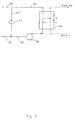
- FIG. 2 illustrates an external respiratory aid apparatus herein shown in cutaway view.
- the external respiratory aid 140 comprises an air/blood mass exchange apparatus 114 herein connected up to air and blood flow apparatus. Whilst in the embodiment shown in Figure 2 there is a single mass transfer apparatus 114, variations are envisaged in which two mass exchange apparatus 114 are arranged in parallel fashion.
- air inlet 122 leads from pump 126 (e.g. in the form of a fan) to direct air in a first direction through the mass exchange apparatus 114 (e.g. having the detailed form of the mass exchange apparatus of Figure 1 ), from which it exits at air outlet 124.
- pump 126 e.g. in the form of a fan
- the air flow is controlled by suitable control of the air pump 126.
- recycling channel 123 may be used to recycle air.
- Restrictor valves 125 and 127 are employed to control the amount of recycled air employed that is pumped back to the air inlet 122.
- a pressure release valve (not shown) is inserted between the air pump 126 and mass exchange apparatus 114.
- the patient's blood flows into the mass exchange apparatus 114 by means of blood inlet 132 and exits via blood outlet 134. It will be appreciated that the blood flow inlet 132 and outlet 134 are connected to the patient's blood supply. Blood flow is governed by the pumping action of blood flow pump 136. The pump is designed to minimize damage to the circulating blood flow. A number of pump designs are possible, and a peristaltic pump is illustrated.
- the respiratory aid apparatus 140 is also connected up to an air filter 150 that may also act as a humidifier. Optionally, the air can also be pre-heated with a simple heat exchange apparatus in contact with the body. As illustrated, the blood flows in a first direction through the apparatus 140 and the air flows in a second direction counter to the direction of blood flow.
- the air flow pump 126; restrictor valves 125, 127; and blood flow pump 136 may be seen to communicate with controller 160, which in turn communicates with sensor 170.
- the sensor 170 is arranged to sense the respiratory demand of a patient (not shown) by sensing of the patient's pulse rate.
- the pulse rate input may be augmented by additional inputs; for example, the oxygen saturation of the venous blood entering the mass exchanger may be sensed.
- the controller 160 controls the pumping action of both pumps 126, 136 in response to signals received from the sensor 160, and hence acts to control the rate of blood / air mass exchange.
- the controller 160 also controls restrictor valves 125 and 127 and hence the air recycling action within the apparatus, which acts to control the levels of carbon dioxide and oxygen in the air flow in response to sensed patient respiratory demand.
- the input tubing 132 to the blood pump136 is arranged to provide blood extraction and return via a single entry point in a vein of a patient.
- An extraction head which is suitable for installation by use of concentric input tubing 132, is illustrated in Figure 3 herein.
- An alternative extraction head using adjacent tubing is illustrated in Figures 9a and 9b herein.
- the vein 180 of a patient receives first 190 and second 192 concentric tubes.
- the tubing is arranged such that the blood flow 182a-b within the vein is counter to the blood flow 112a, 112b to the mass exchange apparatus, which flows in the outer concentric tube 192.
- the blood flow from the mass exchange apparatus 112c within the inner concentric tube 190 flows counter to the blood flow 112a, 112b to the mass exchange apparatus.
- the extraction point is immediately upstream of the return point.
- the external surface of the extraction/return head is designed so that the device can be inserted into the vein 180 at a convenient point and then threaded to a suitable point, for example in the vena cava system.
- the design also allows withdrawal of the device without major surgery. In this way, the use of the external respiratory aid is easily reversible.
- a similar design, as illustrated at Figures 9a and 9b applies for the case where the extraction and return channels are side-by-side, rather then concentric.
- the outer tube may have holes or a mesh through which the blood is extracted.
- the extracted blood 112a, 112b reverses direction to flow through the extraction tube.
- the returned blood 112c is arranged to flow in the same direction as the blood 182a, 182b in the vein from which it is extracted.
- the inner concentric tube 190 By suitably tapering 191 the inner concentric tube 190 at the return point, the returned flow can mingle with the residual flow in the vein with both flows at approximately the same average velocity.
- the vein 680 of a patient receives input tubing comprising two tubes 690, 692 in side-by-side arrangement and received within a third tube 694 of circular cross-section.
- the tubing is arranged such that the blood flow 682a-b within the vein is counter to the blood flow 612a, 612b to the mass exchange apparatus, which flows in one tube 692.
- the blood flow from the mass exchange apparatus 612c within the other tube 690 flows counter to the blood flow 612a, 612b to the mass exchange apparatus.
- This arrangement provides the insertion of a single smooth round tube 694, with no crannies, that minimizes clotting on the outside.
- Figure 4 illustrates an intermediate respiratory aid apparatus herein shown in cutaway view. Part of the apparatus locates within the body of a patient and part locates outside of the body.
- the intermediate respiratory aid comprises an air/blood mass exchange apparatus 214 herein (e.g. having the detailed form of that apparatus of Figure 1 ) connected up to air flow apparatus.
- the mass exchange apparatus 214 is arranged to connect directly with a vein of a patient such that the blood flow is provided by the action of the patient's own heart.
- air inlet 222 leads from pump 226 (e.g. in the form of a fan) to direct air in a first direction through the mass exchange apparatus 214 from which it exits at air outlet 224.
- pump 226 e.g. in the form of a fan
- the air flow is controlled by suitable control of the air pump 226. Blood flows through the mass exchange apparatus 214 (in response to the action of the patient's heart) by means of blood inlet 232 and exits via blood outlet 234.
- the air flow is delivered through a HEPA filter to clean the air before delivering it to the mass exchange apparatus 214.
- recycling channel 223 is used to recycle air from the outlet 223.
- Restrictor valves 225 and 227 are employed to control the amount of recycled air employed that is pumped back to the air inlet 222.
- the air feed may also be humidified and pre-heated if required.
- a pressure release valve (not shown) is inserted between the air pump 226 and mass exchange apparatus 214.
- the air flow pump 226; restrictor valves 225, 227; and blood flow pump 236 may be seen to communicate with controller 260, which in turn communicates with sensor 270.
- the sensor 270 is arranged to sense the respiratory demand of a patient (not shown) by sensing of the patient's pulse rate.
- the pulse rate input may be augmented by additional inputs; for example, the oxygen saturation of the venous blood entering the mass exchanger may be sensed.
- the controller 260 controls the pumping action of both pumps 226, 236 in response to signals received from the sensor 260, and hence acts to control the rate of blood / air mass exchange.
- the controller 260 also controls restrictor valves 223 and 225 and hence the air recycling action within the apparatus, which acts to control the levels of carbon dioxide and oxygen in the air flow in response to sensed patient respiratory demand.
- FIGS 5 and 6 illustrate two different aspects of this control function, which may for example, be implemented using the basic apparatus of either Figures 2 or 4 .
- the flow rate of blood through the mass exchange apparatus 114; 214 is either taken as the whole flow in a vein or, using a controlled pump, adjusted to be a constant fraction of the total blood flow.
- Natural air is employed. Natural air (filtered and/or humidified) is mixed with a recycle 123; 223 from the mass exchange apparatus 114, 214 and the mixed stream fed to the mass exchange apparatus. The output from the mass exchange apparatus 114; 214 is divided, part is recycled and part is exhausted to atmosphere. There is a pump (or fan) in the recycle loop 123, 223 and one or more valves 125, 127; 225, 227 to control the proportion of gas recycled. Both the oxygen and carbon dioxide concentrations can be controlled by suitably adjusting the pumping rate and the recycle proportion (which adjusts the net feed and exhaust rates).
- the patient respiratory demand is sensed by sensor 170; 270 and the oxygen and carbon dioxide concentrations are adjusted responsive thereto by the control action of controller 160; 260 to provide the required mass transfer rates and concentrations.
- pulse rate can be employed to sense respiratory demand.
- a high pulse rate implies a high blood circulation rate which requires high oxygen and carbon dioxide mass transfer rates.
- a low pulse rate implies a low circulation rate and a low patient respiratory demand.
- other non-intrusive measures of respiratory demand can be employed. For example, we could measure strength of the pulse, or blood oxygen saturation. Other methods, essentially based on measuring noise, can also be employed to estimate circulation rate. There is a strong preference for non-intrusive sensing of patient respiratory demand.
- the concentration levels are initially adjusted so that, at rest, the patient has a comfortable heart rate.
- the pump/fan 326 may alternatively be placed in the exit stream from the mass exchange apparatus 314.
- the benefit of placement in the exit stream is that risk of over-pressurization in the mass exchange apparatus is eliminated.
- a valve restrictor (not illustrated) may be placed in the feed stream 321 (or alternatively, in the exhaust stream 328) to stimulate recycle flow. If in the feed stream 321, it produces a low pressure in air flow input 322 at the junction with the air flow recycle stream 323. This low pressure creates a pressure difference across the valve restrictor 325, which enables the recycle flow rate to be controlled. If alternatively, the valve restrictor is in the exhaust stream 328, it produces a high pressure at the junction of air flow output steam 324 and the air flow recycle stream 323.
- valve restrictor 325 may also be adjustable so that total pressure in the system can be adjusted to just below blood pressure (to prevent risk of gas leaking through the membrane and causing bubbles in the blood).
- Figure 5 does not illustrate the mechanism by which the blood is pumped through the mass exchange apparatus 314. Suitable methods have previously been described by reference to Figures 2 and 4 . Also note that Figure 5 illustrates only co-current flow through the mass exchange apparatus 314. The present invention allows also for counter-current or mixed flow.
- f is the fraction of Stream 3 that is recycled.
- the outlet compositions are independent of recycle fraction.
- the oxygen feed rate is a constant fraction of the total feed rate. The area must be sufficient to support the maximum mass-transfer rate without incurring excess pressure drop.
- the targeted mean driving forces depend on the particular mode of operation of the mass exchange apparatus 314 herein.
- the mass exchange apparatus 314 is deployed to provide the majority of the mass transfer. For example, it takes the majority of the blood flow and the lungs are very deficient. In these circumstances, the mass transfer rate and concentrations must closely match those of the natural lung. We then find, by inserting typical values that the mass exchange apparatus 314 must operate in co-current mode.
- the mass exchange apparatus 314 may improve performance to reduce the outlet blood carbon dioxide concentration. There may then be the option to apply the mass exchange apparatus 314 either in co-current or counter-current mode.
- the blood with reduced carbon dioxide can be mixed with blood having excessive carbon dioxide that bypasses the mass exchange apparatus 314.
- the resulting mixture may have close to the natural carbon dioxide concentration.
- the benefit of counter-current flow is that a smaller mass exchange apparatus 314 may be needed.
- the control algorithm is readily adjusted to account for such situations with the same basic processes (such as illustrated at Figure 5 ) described herein.
- Stream “ a” is a pure oxygen stream 402.
- Stream “ n” is an inert gas stream 404, for example pure nitrogen.
- Stream “ c” is a pure carbon dioxide stream 406.
- a flow regulator 401, 403, 405 is employed for each respective stream 402, 404, 406 before they are mixed.
- the streams 402, 404, 406 combine to form the air flow inlet 422 to the mass exchange apparatus 414.
- Other details of the mass exchange apparatus 414 are not shown, but they may correspond to any of those previously described.
- a pressure relief valve 426 set to open if the total pressure is higher than can be safely employed in the mass exchange apparatus 414.
- Each of the flow regulators 401, 403, 405 may be seen to communicate with controller 460, which in turn communicates with sensor 470.
- the sensor 470 is arranged to sense the respiratory demand of a patient (not shown) by sensing of the patient's pulse rate.
- the pulse rate input may be augmented by additional inputs; for example, the oxygen saturation of the venous blood entering the mass exchanger may be sensed.
- the controller 460 controls the flow regulating action of each of the flow regulators 401, 403, 405 in response to signals received from the sensor 460, and hence acts to vary the levels of carbon dioxide, oxygen and inert gas of the inlet air flow 422, and thus, the rate of blood / air mass exchange.
- Figure 6 illustrates a mechanism for mixing three gases including the following features:
- the second approach illustrated by Figure 6 may be riskier than the first approach illustrated at Figure 5 .
- a gas mixture could pass through the mass exchange apparatus 414 that causes death within seconds. The risk is present both for fail-open and for fail-closed conditions.
- stream n could be a nitrogen/oxygen/carbon dioxide mixture with sufficient oxygen to support life at rest.
- the carbon dioxide concentration would be high enough to guard against respiratory shut-down.
- the other feeds would also have concentrations that would, if used on their own, support life.
- a simpler variant to that shown at Figure 6 has just two feed streams, one suitable for mass transfer at rest and the other for mass transfer under maximum exertion.
- the controller 460 then only manipulates two flow regulators to give a composition appropriate for any level of respiratory demand between rest and maximum exertion.
- the actual feed-stream concentrations would depend on the mass exchange apparatus area and on how the mass exchange apparatus 414 was deployed).
- This approach would greatly reduce the risks of equipment failure. Compared with using an air feed, there is still the risk that an incorrect cylinder could be fitted. Such risks can be further reduced by including gas analysers for oxygen and carbon dioxide. Any system using bottled gas supplies will be non-portable. Hence, the additional weight of analysers would not be significant.
- the mixing (as illustrated in Figure 6 ) is done remote from the patient (with remote monitoring of pulse rate) and the mixed gases supplied through a sufficiently long feed tube to allow mobile patients to exercise.
- the exhaust from the mass exchange apparatus 414 is discharged to atmosphere (possibly after passage through a heat exchanger).
- the present invention encompasses intermediate systems between the two aspects described above.
- Use of an enhanced oxygen concentration can reduce the mass exchange area.
- the size and mass of any bottled gas feed exceeds the size and mass of a larger mass exchange apparatus using natural air.
- the Applicant has recognized that control is of particular importance for two reasons.
- the first reason arises because a mass exchange apparatus for use in blood oxygenation is typically a continuous flow apparatus of fixed area.
- the second reason arises because the mass transfer coefficient for carbon dioxide in a mass exchange apparatus is typically more than an order of magnitude greater than that for oxygen.
- a natural lung pumps at a rate depending on respiratory demand. Breathing is both faster and deeper during periods of high demand.
- the mass transfer coefficient for carbon dioxide in natural lungs is only about a factor of two greater than that for oxygen.
- the flow rate of blood through the mass exchange apparatus must be proportional to the blood flow rate through the heart.
- the required control action can be achieved by setting the flow rate through the mass exchange apparatus proportional to heart rate. This proportionality may suffice for patients not expected to undertake strenuous activity.
- a correction must be applied related to the strength of the heart beat.
- blood circulation rate is proportional to pulse rate.
- blood gas concentrations change little.
- respiration rate is also proportional to pulse rate.
- the tissues take more oxygen from the blood.
- the venous blood returning to the lungs has lower oxygen concentration and higher carbon dioxide concentration.
- monitoring of the blood oxygen saturation is also required.
- the respiratory demand is then proportional to the product of the blood circulation rate and the difference between arterial and venous blood oxygen-saturation levels.
- Table 1 gives typical partial pressures for a healthy person. We will concentrate just on the blood phase equilibrium partial pressures. If the mass exchange apparatus is to reproduce the performance of the human lung, it must have the same input and output partial pressures.
- the mean driving force to use in equation (1) depends on the flow pattern and the relationship between concentration in blood and equilibrium partial pressure. (See, for example, Coulson J M and Richardson J F, Chemical Engineering, Volume 1 (Fluid Flow, Heat Transfer and Mass Transfer), Butterworth Heinmann, Oxford, 2000 ). Such values are needed for detailed design. However, we can illustrate the problem by taking a mean oxygen partial pressure over the blood. We take a value of 9 kPa, which is between the venous value of 5.3 and the arterial value of 12.3.
- the maximum mean air-side oxygen partial pressure is 21 kPa. That gives a mean driving force of around 12 kPa.
- the normal mean driving force should be less than the maximum. If we are to give the patient a 2:1 respiratory range, it should be half the maximum. In that case, for normal operation, we should have a mean driving force of no more than 6 kPa.
- the corresponding mean gas partial pressure is 15 kPa (which corresponds to 15% oxygen). For wider dynamic ranges, lower normal operating partial pressures are required. Thus, we would operate with a considerably lower mean partial pressure than is the case for normal lungs.
- the gas-side partial pressure lies between 21 kPa on the in breath and 16 kPa on the out breath).
- the driving force should be a fraction of this maximum pressure difference.
- the mean oxygen partial pressure should be about 54 kPa.
- the oxygen may enter with a partial pressure of 56 kPa (gas mixture of 56 mole percent oxygen) and leave with a partial pressure of 52 kPa (mixture having 52 mole percent oxygen).
- Equation (1) applies equally to Carbon Dioxide mass transfer.
- the mass transfer coefficient for carbon dioxide is so high that carbon dioxide will leave the blood until there is a very small driving force.
- the control problem is then not to transfer sufficient carbon dioxide, but to control the blood carbon dioxide concentration by maintaining a sufficient gas-side partial pressure. Consequently, there is a problem with both pure air and pure oxygen feeds. In both cases, the concentration of carbon dioxide in the feed is zero, or close to zero.
- the concentration (partial pressure) of carbon dioxide is likely also to be low at the outlet of the mass exchange apparatus. Hence, there is limited scope for controlling the blood carbon dioxide concentration.
- the equilibrium partial pressure will approximately equal the outlet gas concentration. It will be proportional to the metabolic rate divided by the gas flow rate.
- Table 1 are indicative average values. In practice, they differ from person to person, and are difficult to measure accurately, as illustrated by the figures in Table 1 a. ( Nemery B, Nullens W, Veriter C, Brasseur L and Frans A, Effects of Gas Density on Pulmonary Gas Exchange of Normal Man at Rest and During Exercise, Pflügers Arch, pp57 - 61, 1983 ). The values in Table 1 a were obtained for breathing air, and averaged from measurements on six healthy males at rest. Table 1a. Oxygen and Carbon Dioxide partial Pressures breathing air. Stream O 2 PP, kPa Standard Deviation. CO 2 PP, kPa Standard Deviation. Arterial Blood 12.7 1.3 5.01 0.72 Alveolar Air 14.2 1.4 4.96 0.84 Difference 1.5 0.5 0.06 0.16
- the alveolar air is separated from the inlet air by a volume in which mixing occurs (often modelled as a dead volume).
- a volume in which mixing occurs (often modelled as a dead volume).
- the alveolar air composition varies little during the breathing cycle.
- This dead volume and the bronchial passageways can be lumped into an overall mass transfer resistance between the air at the mouth (nose) and the carbon dioxide in the blood. Similarly, the resistance can be averaged over the breathing cycle.
- equation (1) gives, for the overall breathing cycle in the natural lungs:
- U CO ⁇ 2 / U O ⁇ 2 m CO ⁇ 2 / m O ⁇ 2 ⁇ ⁇ ⁇ c O ⁇ 2 / ⁇ ⁇ c C O ⁇ 2
- the relevant mean driving forces depend on whether the blood and air flows are considered to be co-current or counter-current. For a cyclic breathing process, a mean between co-current and counter-current applies. Hence, we will scope the range of values by considering the two extremes. For both flow patterns, we take the relevant logarithmic mean driving forces (see Coulson and Richardson).
- Table 2 gives the steps in the calculation of the relative mass-transfer coefficients for lungs. Table 2. Calculation of relative mass transfer coefficients in human lungs.
- the ratio of mass transfer coefficients is about 2.5.
- the significance of the ratio is that, for the same driving force, the rate of mass transfer of carbon dioxide is 2.5 times greater than that of oxygen. Alternatively, for the same mass transfer rate, the driving force for carbon dioxide can be 2.5 times less.
- Table 3 gives the corresponding calculations for membrane mass exchange apparatus with negligible mass transfer resistance in the membrane.
- a membrane mass exchange apparatus eliminates the gas-side mass-transfer resistance. Thus, there is no dead volume and no length of bronchi for the gases to diffuse through. However, the blood-side mass-transfer resistance remains similar.
- For oxygen the resistance results from diffusion of the oxygen through the liquid phase, diffusion into the red corpuscles and the relatively slow reaction of dissolved oxygen with haemoglobin.
- For carbon dioxide the resistance results from diffusion through the liquid phase and the reaction of dissolved carbon dioxide to form primarily bicarbonate ions. The average diffusion distance is less for carbon dioxide because bicarbonate ions can form throughout the bulk of the liquid.
- the driving force for carbon dioxide is less than 5% of that for oxygen. Indeed, as for mass transfer from alveolar air to arterial blood, in Tables 1 and 1 a, the driving force may be indistinguishable from zero.
- the arterial carbon dioxide partial pressure equals that of the inlet air (i.e. nearly zero).
- the arterial carbon dioxide partial pressure would equal that in the exhaled air, namely 4 kPa. In both cases, the carbon dioxide concentration would be much lower than the level expected by the body's natural control mechanism.
- the present invention provides independent means of controlling blood oxygen and carbon dioxide levels. In this way, a suitable controller can mimic the natural relationship between blood oxygen and carbon dioxide levels. By mimicking the natural relationship, the natural respiratory control mechanism can respond to changing metabolic rates in an effective and stable manner.
- an improved mixed-flow mass exchange apparatus with particular application in blood oxygenation.
- This aspect refines the design of a mass exchange apparatus as described in Applicant's earlier-published PCT Patent Application Number No. WO2005/118025 .
- This aspect of the invention provides a means of separately adjusting the mass transfer rate and outlet concentrations of two components in the outlet stream from a mass exchange apparatus. Specifically, it provides a means of adjusting oxygen and carbon dioxide mass transfer rates to and from blood and controlling the concentrations of these two dissolved gases in the blood.
- This aspect of the present invention exploits the fact that, for given liquid and gas phase concentrations, counter-current flow gives higher mass transfer rates than co-current flow.
- Cross-current flow gives intermediate mass transfer rates.
- a mixed-flow mass exchange apparatus that can change smoothly through a range of flow patterns. Thus, it can start as a pure co-current flow device. It can be adjusted to a mixed co-current/cross-current device with an increasing proportion of cross flow. Adjustment extends to allow a pure cross-current flow device. Further adjustment allows a mixed cross-current/counter-current device and ultimately a pure counter-current device.
- the mixed-flow mass exchange apparatus has a range of adjustment that allows a smooth progression from co-current to counter-current flow. There is a corresponding smooth increase in mass transfer rate.
- a second adjustment is available in that the total flow rate of one phase (for example, the gas or air phase) can be increased. This increase (by reducing the concentration change across the mass exchanger) also increases mass transfer rates.
- the two methods of adjusting mass transfer rates impact the mass transfer of individual components differently. In this way, the mass transfer rates of oxygen to blood and carbon dioxide from blood can be adjusted separately.
- the device is capable of controlling the concentrations and mass transfer rates of two components without necessarily employing any recycling of air flow.
- a mixed-flow mass exchange apparatus for use in mass exchange comprising
- said apparatus additionally comprises an adjuster that enables independent adjustment of the concentration of the carbon dioxide and oxygen in the blood flow.
- the mass exchange apparatus herein, comprises plural blood flow conduits for defining a blood flow. That blood flow is from a blood flow inlet to a blood flow outlet provided to the apparatus (e.g. blood flows from a blood flow inlet through the plural blood flow conduits to the blood flow outlet).
- a blood flow inlet to a blood flow outlet provided to the apparatus
- plural blood flow inlets and/or blood flow outlets are employed in any suitable arrangement or configuration.
- the mass exchange apparatus herein, comprises plural air flow conduits for defining an air flow. That air flow is from an air flow inlet to an air flow outlet provided to the apparatus (e.g. air flows from air flow inlet through the plural air flow conduits to the air flow outlet).
- air flow inlets and/or air flow outlets are employed in any suitable arrangement or configuration.
- the plural blood flow conduits and plural air flow conduits may take the form of tubes or closely-spaced plates.
- the plural blood flow conduits and plural air flow conduits at least partially comprise gas-permeable membrane material.
- the conduits are for example, arranged relative to each other such as to enable transfer, through the membrane material, of oxygen from an air flow to the blood and transfer of carbon dioxide from a blood flow to the air flow.
- the walls defining the blood flow and air flow conduits may be separately formed and arranged relative to each other to enable the necessary exchange of air (oxygen) and carbon dioxide.
- the blood flow and air flow conduits share at least some common walls, again with the arrangement selected to enable the necessary exchange of air (oxygen) and carbon dioxide.
- the blood flow conduits and/or air flow conduits have a diameter (or cross-section of non-circular conduit) and/or spacing of less than 0.5 mm.
- the adjuster comprises a valve or similar mechanism, which typically acts under the control of a controller in response to sensing by a sensor.
- the sensor detects the pulse rate of a patient, which indicates patient respiratory demand for oxygen.
- the sensor detects the breathing rate of the patient and/or the blood circulation rate of the patient, each of which is indicative of the patient respiratory demand for oxygen.
- the senor communicates with the controller by suitable communication means.
- the sensor is typically, an electronic sensor and communication with the controller is typically via wired or wireless electronic transmission means.
- the controller suitably acts to control the rate of blood/air mass exchange by separate control of the concentrations of carbon dioxide and oxygen responsive to the sensing of patient respiratory demand by the sensor.
- the adjuster locates at either the blood flow inlet / outlet or the air flow inlet / outlet.
- the adjuster comprises an air flow adjuster for adjusting the total flow rate of the air flow.
- the air flow adjuster comprises a valve and/or pump.
- the adjuster comprises a flow selector for selecting the relative flow pattern of the blood flow and the air flow.
- the relative flow pattern is selected from the group consisting of co-current flow, counter-current flow, a mixed flow that is partly cross-current and partly co-current and a mixed flow that is partly cross-current and partly counter-current.
- the flow selector comprises a multi-way valve (e.g. a three-way valve).
- the flow may comprise a combination of one or more valves and one or more flow restrictors.
- the multi-way valve permits the proportion of cross-flow either to be infinitely adjustable or alternatively, to be adjustable in small steps.
- Embodiments are envisaged in which different flow patterns are mixed and matched to produce combination flow patterns of any suitable type.
- an air flow inlet multi-way valve enables separation of the air flow into plural separate air flows for directing to plural separate air flow inlets of the plural air flow conduits.
- an air flow outlet multi-way valve enables separation of the air flow into plural separate air flows for directing from plural separate outlets of the plural air flow conduits.
- a blood flow inlet multi-way valve enables separation of the blood flow into plural separate blood flows for directing to plural separate blood flow inlets of the plural blood flow conduits.
- a blood outlet multi-way valve enables separation of the blood flow into plural separate blood flows for directing from plural separate blood flow outlets of the plural blood flow conduits.
- the advantage of a mass exchange apparatus that does not employ recycle is that the mass exchange area can be smaller, and the flow rate through the mass exchange apparatus can be lower.
- the range of transfer rates and concentrations may be less then for recycled systems. It is possible to combine mixed flow and recycle to give a wider range of control options than either technology can achieve on its own.
- the flow of one component is from bottom to top.
- the mass exchange apparatus 514 e.g. having the detailed form of that mass exchange apparatus of Figure 1
- the mass exchange apparatus 514 can operate in any orientation.
- blood comes in the bottom, passes through an array of fine tubes or closely spaced plates, and exits at the top.
- Air (or an oxygen-containing gas) enters through air inlet 510 and exits at air outlet 512.
- First multi-way valve 520 is provided to the air inlet 510 and second multi-way valve 522 is provided to the air outlet 512.
- first valve 520 is switched such that the inlet air enters the mass exchange apparatus as stream 1.
- the first valve 520 closes streams 2 and 3.
- Second valve 522 is switched such that the outlet gas stream from the exchanger exits as stream 6.
- Second valve 522 closes stream 4 and 5.
- the gas stream enters at the bottom (stream 1) flows concurrently with the liquid stream and exits from the top (stream 6).
- first valve 520 is switched such that air enters the exchanger through both streams 1 and 2.
- First valve 520 closes stream 3.
- Second valve 522 is switched such that air exits the exchanger through both streams 5 and 6.
- Second valve 522 closes stream 4.
- the flow is intermediate between co-current and cross-current.
- the first and second valves 520, 522 are adjustable allowing a range of flows from 100% co-current to 100% cross-current.
- first valve 520 is switched such that air enters the exchanger through stream 2.
- First valve 520 closes streams 1 and 3.
- Second valve 522 is switched such that air exits through stream 5.
- Second valve 522 closes streams 4 and 6.
- the gas flow is then cross-current, namely at right-angles to the liquid flow.
- first valve 520 allows flow through steams 2 and 3, and blocks stream 1.
- second valve 522 allows flow through streams 4 and 5, and blocks stream 6.
- the first and second valves 520, 522 are adjustable to allow a range of flows from 100% cross-current to 100% counter-current.
- first valve 520 allows flow through stream 3 and no flow through streams 1 and 2.
- second valve 522 allows flow through stream 4 and no flow through streams 5 and 6.
- ⁇ p lm ⁇ ⁇ p 1 - ⁇ ⁇ p 2 / ln ⁇ ⁇ p 1 / ⁇ ⁇ p 2
- equation (4) gives a good approximation to the relevant mean driving force.
- Table 4 shows the individual pressure differences as “Diff (co-)” (difference for co-current flow) and “Diff (counter-)” (difference for counter-current flow).
- Diff (co-) difference for co-current flow
- Diff (counter-) difference for counter-current flow
- the mass transfer coefficient for carbon dioxide is very high. Hence, with a higher driving force, the blood carbon dioxide concentration will fall until the driving force is again very low. Thus, the carbon dioxide blood partial pressure will be close to the gas-side partial pressure with which it is matched.
- the gas-side partial pressure shown in Table 1 is 5.5 kPa.
- the blood-side partial pressure shown is 5.6 kPa.
- the corresponding gas-side partial pressure is 0 kPa.
- the expected blood-side partial pressure will be very low (for example, as low as 0.1 kPa).
- the mixed-flow mass exchange apparatus 514 provides a smooth transition both for mass transfer rate and outlet blood carbon dioxide concentration.
- the outlet blood carbon dioxide concentration should change smoothly from 5.6 kPa to 0.1 kPa as the mass exchange apparatus 514 changes from co-current to counter-current flow via intermediate mixed-flow patterns.
- Oxygen transfer rate and concentration is much less sensitive to flow pattern because larger driving forces are required so that the concentration in the gas phase varies less.
- total mass-transfer rate can be changed by changing the total flow rate of the gas phase.
- this aspect of the invention allows almost any outlet carbon dioxide blood concentration to be selected independent of the oxygen mass-transfer rate.
- the mixed flow mass exchange apparatus enables control of two outlet concentrations whenever the mass transfer coefficient of one component differs significantly from that of another.
- the illustration shows a liquid phase (blood) with a fixed flow direction, and a gas phase (air) with an adjustable flow pattern.
- the gas phase may be advantageous for the gas phase to flow in a fixed direction and for the liquid phase to have an adjustable flow pattern.
- the apparatus is also equally applicable to gas/gas and to liquid/liquid mass exchange.
- the preferred physical form of the mixed-flow mass-exchange apparatus 514 is a cuboid, as illustrated in Figure 8 .
- the mass exchange apparatus 514 is shown flattened to give a reasonably long flow path for the gas phase in both horizontal flow and vertical flow. In this way, gas distribution can be improved.
- a flattened cuboid has the additional advantage that the exchanger can be placed against the body of the patient to maintain temperatures close to blood temperature.
Landscapes
- Health & Medical Sciences (AREA)
- Heart & Thoracic Surgery (AREA)
- Urology & Nephrology (AREA)
- Vascular Medicine (AREA)
- Emergency Medicine (AREA)
- Hematology (AREA)
- Anesthesiology (AREA)
- Biomedical Technology (AREA)
- Engineering & Computer Science (AREA)
- Life Sciences & Earth Sciences (AREA)
- Animal Behavior & Ethology (AREA)
- General Health & Medical Sciences (AREA)
- Public Health (AREA)
- Veterinary Medicine (AREA)
- Cardiology (AREA)
- External Artificial Organs (AREA)
Claims (22)
- Massenaustauschvorrichtung (114) zur Verwendung im Blut/Luft-Massenaustausch, die Folgendes aufweist(a) mehrere Blutstromleitungen (10a-10c) zum Definieren eines Blutstroms von einem zu ihnen bereitgestellten Blutstromeinlass (132) ;(b) mehrere Luftstromleitungen (20a-20c) zum Definieren eines Luftstroms (22a-22c) von einem zu ihnen bereitgestellten Luftstromeinlass (122);wobei die genannten mehreren Luftstromleitungen (20a-20c) und die genannten mehreren Blutstromleitungen (10a-10c) wenigstens teilweise gasdurchlässiges Membranmaterial (20a-20c) aufweisen und die Leitungen relativ zueinander angeordnet sind, um den Transfer von Sauerstoff von dem genannten Luftstrom zu dem genannten Blutstrom und den Transfer von Kohlendioxid von dem genannten Blutstrom zu dem Luftstrom durch das genannte Membranmaterial zu ermöglichen, und wobei die genannte Vorrichtung außerdem Folgendes aufweist(c) einen Sensor (170) zum Erfassen des Atmungsbedarfs eines Patienten und(d) einen Regler (160) zum Regeln der Blut/Luft-Massenaustauschrate durch die auf die Erfassung des Atmungsbedarfs des Patienten durch den Sensor reagierende, getrennte Regelung des Kohlendioxid- und des Sauerstoffgehalts in dem Luftstrom, wobei der Luftstromeinlass mehrere Fluidstromzufuhren aufnimmt, die eine Kohlendioxidzufuhr aufweisen sowie entweder:• eine Luftzufuhr oder• eine Sauerstoffzufuhr und eine Inertgaszufuhr.
- Massenaustauschvorrichtung nach Anspruch 1, wobei der genannte Regler den Kohlendioxid- und den Sauerstoffgehalt in dem Luftstrom an dem Luftstromeinlass separat regelt.
- Massenaustauschvorrichtung nach Anspruch 1 oder 2, die zusätzlich einen Blutstromregler zum Regeln der Strömungsgeschwindigkeit des Blutstroms aufweist.
- Massenaustauschvorrichtung nach Anspruch 3, wobei der genannte Blutstromregler die Strömungsgeschwindigkeit des Blutstroms so regelt, dass sie proportional zum Blutstromdurchsatz durch das Herz und die großen Venen eines Patienten ist.
- Massenaustauschvorrichtung nach einem der vorhergehenden Ansprüche, die außerdem einen Luftrückführungskreislauf aufweist und wobei der Luftstromeinlass sowohl eine Primärluftstromzufuhr als auch eine Rückführungsluftstromzufuhr aus dem genannten Luftrückführungskreislauf aufnimmt.
- Massenaustauschvorrichtung nach Anspruch 5, wobei der Regler zum Regeln der relativen Anteile der am Luftstromeinlass aufgenommenen Primärluftstromzufuhr und Rückführungsluftstromzufuhr wirkt.
- Massenaustauschvorrichtung nach Anspruch 6, wobei der Regler zum Regeln der Rückführungsrate des Luftrückführungskreislaufs wirkt.
- Massenaustauschvorrichtung nach Anspruch 6, wobei der Regler zum Regeln der relativen Zufuhrrate der Primärluftstromzufuhr und der Rückführungsluftstromzufuhr wirkt.
- Massenaustauschvorrichtung nach einem der vorhergehenden Ansprüche, wobei der Regler zum Regeln der relativen Anteile von jeder der mehreren an dem Luftstromeinlass aufgenommenen Fluidstromzufuhren wirkt.
- Massenaustauschvorrichtung nach Anspruch 9, wobei der Regler zum Regeln der relativen Durchsätze von jeder der mehreren am Luftstromeinlass aufgenommenen Fluidstromzufuhren wirkt.
- Massenaustauschvorrichtung nach einem der vorhergehenden Ansprüche, der außerdem einen sekundären Massenaustauscher enthält, um (in) einer Abführung von der Massenaustauschvorrichtung Kohlendioxid zu entziehen und Sauerstoff aufzufüllen.
- Massenaustauschvorrichtung nach einem der vorhergehenden Ansprüche, die mehrere Sensoren zum Erfassen des Atmungsbedarfs des Patienten aufweist.
- Massenaustauschvorrichtung nach Anspruch 12, wobei jeder der mehreren Sensoren einen anderen Parameter in Bezug auf den Atmungsbedarf des Patienten erfasst.
- Massenaustauschvorrichtung nach einem der vorhergehenden Ansprüche, wobei der Sensor oder wenigstens einer der mehreren Sensoren die Pulsfrequenz eines Patienten erfasst.
- Massenaustauschvorrichtung nach einem der Ansprüche 1 bis 13, wobei der Sensor oder wenigstens einer der mehreren Sensoren die Atemfrequenz eines Patienten erfasst.
- Massenaustauschvorrichtung nach einem der Ansprüche 1 bis 13, wobei der Sensor oder wenigstens einer der mehreren Sensoren die Blutkreislaufgeschwindigkeit eines Patienten erfasst.
- Massenaustauschvorrichtung nach einem der Ansprüche 1 bis 13, wobei der Sensor oder wenigstens einer der mehreren Sensoren die Sauerstoffkonzentration in venösem Blut eines Patienten erfasst.
- Massenaustauschvorrichtung nach einem der Ansprüche 1 bis 13, wobei der Sensor oder wenigstens einer der mehreren Sensoren die Pulsstärke eines Patienten erfasst.
- Massenaustauschvorrichtung nach einem der Ansprüche 1 bis 13, wobei der Sensor oder wenigstens einer der mehreren Sensoren die Blutsauerstoffsättigung erfasst.
- Massenaustauschvorrichtung nach einem der vorhergehenden Ansprüche, wobei der Luftstrom so angeordnet ist, dass er eine Kombination ist aus einem Luftstrom, der zum Blutstrom gegenströmig ist, und einem Luftstrom, der mit dem Blutstrom gleichströmig ist.
- Atmungsunterstützungsvorrichtung zum externen Anschluss an einen Patienten, die Folgendes aufweist:(a) wenigstens eine Massenaustauschvorrichtung nach einem der Ansprüche 1 bis 20;(b) eine Luftpumpe zum Pumpen von Luft durch die genannten Luftleitungen, um den Luftstrom zu definieren; und(c) eine Blutpumpe zum Pumpen von Blut durch die genannten Blutleitungen, um den Blutstrom zu definieren.
- Eine Zwischen-Atmungsunterstützungsvorrichtung zum internen Anschluss an einen Patienten, die Folgendes aufweist:(a) wenigstens eine Massenaustauschvorrichtung nach einem der Ansprüche 1 bis 20; und(b) eine Luftpumpe zum Pumpen von Luft durch die genannten Luftleitungen.
Applications Claiming Priority (2)
| Application Number | Priority Date | Filing Date | Title |
|---|---|---|---|
| GB0607410A GB2437254B (en) | 2006-04-13 | 2006-04-13 | Blood/air mass exchange apparatus |
| PCT/GB2007/050114 WO2007119073A1 (en) | 2006-04-13 | 2007-03-08 | Blood/air mass exchange apparatus |
Publications (2)
| Publication Number | Publication Date |
|---|---|
| EP2004255A1 EP2004255A1 (de) | 2008-12-24 |
| EP2004255B1 true EP2004255B1 (de) | 2015-10-28 |
Family
ID=36571740
Family Applications (1)
| Application Number | Title | Priority Date | Filing Date |
|---|---|---|---|
| EP07712992.2A Not-in-force EP2004255B1 (de) | 2006-04-13 | 2007-03-08 | Blut/luft-massen-austauschgerät |
Country Status (8)
| Country | Link |
|---|---|
| US (1) | US8529834B2 (de) |
| EP (1) | EP2004255B1 (de) |
| JP (1) | JP2009533122A (de) |
| AU (1) | AU2007238401A1 (de) |
| CA (1) | CA2649023A1 (de) |
| ES (1) | ES2560638T3 (de) |
| GB (1) | GB2437254B (de) |
| WO (1) | WO2007119073A1 (de) |
Families Citing this family (42)
| Publication number | Priority date | Publication date | Assignee | Title |
|---|---|---|---|---|
| US8470071B2 (en) * | 2006-09-25 | 2013-06-25 | Dais Analytic Corporation | Enhanced HVAC system and method |
| GB0704479D0 (en) * | 2007-03-08 | 2007-04-18 | Haemair Ltd | Prosthetic lung |
| WO2008127732A2 (en) | 2007-04-12 | 2008-10-23 | The General Hospital Corporation | Biomimetic vascular network and devices using the same |
| EP2200931B1 (de) | 2007-09-19 | 2017-06-07 | The Charles Stark Draper Laboratory, Inc. | Mikrofluidstrukturen mit kreisförmigem querschnitt |
| WO2009102751A2 (en) | 2008-02-11 | 2009-08-20 | The General Hospital Corporation | System and method for in vitro blood vessel modeling |
| US8985106B2 (en) * | 2009-06-05 | 2015-03-24 | Resmed Limited | Methods and devices for the detection of hypopnoea |
| US8444749B2 (en) * | 2009-06-10 | 2013-05-21 | L'air Liquide, Societe Anonyme Pour L'etude Et L'exploitation Des Procedes Georges Claude | Method and system for membrane-based gas recovery |
| WO2011082323A1 (en) * | 2009-12-31 | 2011-07-07 | The Charles Stark Draper Laboratory, Inc. | Microfluidic device facilitating gas exchange, and methods of use and manufacture thereof |
| JP2013534461A (ja) | 2010-05-26 | 2013-09-05 | ザ チャールズ スターク ドレイパー ラボラトリー インク | 微細加工された人工肺補助装置ならびにその使用および製造の方法 |
| DE102011100439A1 (de) * | 2011-05-04 | 2012-11-08 | Dritte Patentportfolio Beteiligungsgesellschaft Mbh & Co.Kg | Austauscher-Vorrichtung |
| GB201108495D0 (en) | 2011-05-20 | 2011-07-06 | Haemair Ltd | Gas/fluid exchange apparatus |
| DE102011052189A1 (de) * | 2011-07-27 | 2013-01-31 | Maquet Vertrieb Und Service Deutschland Gmbh | Elektronisch gesteuerte Gasmischeinheit zum Zuführen eines Spülgases zu einem Oxygenerator |
| DE102011052188A1 (de) * | 2011-07-27 | 2013-01-31 | Maquet Vertrieb Und Service Deutschland Gmbh | Anordnung zum Erwärmen und/oder Befeuchten des Spülgases eines Oxygenerators |
| DE102011052187A1 (de) * | 2011-07-27 | 2013-01-31 | Maquet Vertrieb Und Service Deutschland Gmbh | Anordnung zum Entfernen von Kohlenstoffdioxid aus einem exkorporalen Blutstrom mittels Inertgasen |
| CN103083741B (zh) * | 2011-11-02 | 2016-03-09 | 深圳光启高等理工研究院 | 气血交换血氧饱和度监测装置 |
| US9180239B2 (en) * | 2011-12-05 | 2015-11-10 | The Charles Stark Draper Laboratory, Inc. | Methods for reducing the blood priming volume and membrane surface area in microfluidic lung assist devices |
| WO2014028688A1 (en) * | 2012-08-16 | 2014-02-20 | Erickson Dirk Jerome | Exsanguination preventing device |
| EP3228338B1 (de) | 2013-04-01 | 2019-09-25 | Terumo Kabushiki Kaisha | Zirkulationsvorrichtung und verfahren zur steuerung davon |
| WO2015164618A1 (en) | 2014-04-23 | 2015-10-29 | The Charles Stark Draper Laboratory, Inc. | Blood oxygenator |
| KR101608484B1 (ko) | 2014-06-13 | 2016-04-05 | 강원대학교산학협력단 | 등압 기체교환장치 |
| AU2015350026B2 (en) * | 2014-11-19 | 2020-08-13 | Breethe, Inc. | Artificial lung system and its methods of use |
| GB2557863B (en) * | 2014-12-03 | 2020-09-16 | Spectrum Medical Ltd | Ventilation System |
| EP3090769A1 (de) * | 2015-05-07 | 2016-11-09 | Novalung GmbH | Tragbare gasaustauschvorrichtung |
| CA3025353A1 (en) * | 2016-05-27 | 2017-11-30 | The Charles Stark Draper Laboratory, Inc. | Biomimetic microfluidic device for high efficiency carbon dioxide removal from patients at low blood flow rates |
| JP6170603B2 (ja) * | 2016-09-01 | 2017-07-26 | テルモ株式会社 | 循環装置及びその制御方法 |
| JP7086074B2 (ja) * | 2016-12-08 | 2022-06-17 | マケット・クリティカル・ケア・アーベー | Co2除去のためのシステム |
| DE102016015059B4 (de) * | 2016-12-19 | 2020-11-12 | Drägerwerk AG & Co. KGaA | Vorrichtung zum extrakorporalen Blutgasaustausch |
| EP3427772B1 (de) * | 2017-07-10 | 2023-05-03 | B. Braun Avitum AG | Oxygenatoreinheit mit druckentlastungsventil |
| DK3668556T3 (da) | 2017-08-15 | 2026-03-02 | Univ Maryland | Dobbeltkammergasveksler |
| US11499128B2 (en) | 2017-09-22 | 2022-11-15 | The Regents Of The University Of Colorado | Organ-on-chip microphysiological system |
| US11364333B2 (en) | 2017-10-10 | 2022-06-21 | University Of Maryland, Baltimore | Bidirectional flow catheter |
| US11707559B2 (en) | 2017-10-16 | 2023-07-25 | Terumo Cardiovascular Systems Corporation | Extracorporeal oxygenator with integrated air removal system |
| WO2019157464A1 (en) | 2018-02-09 | 2019-08-15 | The Regents Of The University Of Colorado, A Body Corporate | Bioprinter and methods of manufacturing an organomimetic device |
| US11980705B2 (en) | 2018-03-02 | 2024-05-14 | Spectrum Medical Ltd. | Oxygenation system |
| GB2574015A (en) * | 2018-05-22 | 2019-11-27 | Spectrum Medical Ltd | Blood processing system |
| US11480560B2 (en) | 2018-06-11 | 2022-10-25 | The Regents Of The University Of Colorado, A Body Corporate | Delivery of aerosolized respiratory pathogens |
| GB2583532B (en) | 2019-05-03 | 2023-04-05 | Spectrum Medical Ltd | Control system |
| GB2584109A (en) * | 2019-05-21 | 2020-11-25 | Haemair Ltd | Control system |
| CN115282412B (zh) * | 2022-01-14 | 2023-08-25 | 温州医科大学 | 经鼻腔进入血循环的给药装置及其应用方法 |
| US20240033408A1 (en) * | 2022-07-28 | 2024-02-01 | Cardiacassist, Inc. | Extracorporeal life support system with blood recirculation pathway |
| WO2024084381A1 (en) * | 2022-10-18 | 2024-04-25 | Reuvers Eduard Johannis Adrianus | System, method, and apparatus to evaluate breathing response of user |
| DE102023102145A1 (de) * | 2023-01-30 | 2024-08-01 | Fresenius Medical Care Deutschland Gmbh | Blutbehandlungsvorrichtung zum Gasaustausch |
Family Cites Families (27)
| Publication number | Priority date | Publication date | Assignee | Title |
|---|---|---|---|---|
| FR1597874A (de) * | 1968-12-16 | 1970-06-29 | ||
| FR2197565B1 (de) * | 1972-08-30 | 1975-03-07 | Rhone Poulenc Ind | |
| US4493692A (en) * | 1982-09-29 | 1985-01-15 | Reed Charles C | Blood gas concentration control apparatus and method |
| US4619643A (en) * | 1983-07-25 | 1986-10-28 | Bai Chao Liang | Catheter |
| US4568327A (en) * | 1984-02-27 | 1986-02-04 | Universite De Sherbrooke | Method and apparatus for the removal of gases physically dissolved by dialysis in the blood |
| US4610656A (en) * | 1984-08-21 | 1986-09-09 | Mehealus Partnership | Fully portable semi-automatic mechanical heart-lung substitution system and method |
| ZA8680B (en) * | 1985-01-08 | 1987-08-26 | Mcneilab Inc | Mass transfer device having a microporous,spirally wound hollow fiber membrane |
| CA1330285C (en) * | 1987-12-22 | 1994-06-21 | Geoffrey S. Martin | Triple lumen catheter |
| US5103814A (en) * | 1988-04-28 | 1992-04-14 | Timothy Maher | Self-compensating patient respirator |
| DE4320198C1 (de) * | 1993-06-18 | 1994-07-14 | Fresenius Ag | Vorrichtung zum Gasaustausch, insbesondere zum Oxygenieren von Blut |
| US5601714A (en) * | 1994-06-30 | 1997-02-11 | Polystan Holding A/S | Device for filtration and collection of blood |
| JPH08182758A (ja) | 1994-12-28 | 1996-07-16 | Hideto Kaneyasu | 人工肺自動制御装置 |
| US6004511A (en) * | 1995-09-01 | 1999-12-21 | Baxter International Inc. | Hollow fiber oxygenator |
| US6041777A (en) * | 1995-12-01 | 2000-03-28 | Alliance Pharmaceutical Corp. | Methods and apparatus for closed-circuit ventilation therapy |
| US5609632A (en) * | 1996-03-18 | 1997-03-11 | Medtronic, Inc. | Method of fabricating an artificial lung |
| US5871693A (en) * | 1996-06-07 | 1999-02-16 | Minnesota Mining And Manufacturing Company | Modular blood treatment cartridge |
| US5810759A (en) * | 1997-03-27 | 1998-09-22 | Michigan Critical Care Consultants, Inc. | Control system for regulating gas exchange in extracoporeal circulation |
| US6642045B1 (en) * | 1997-04-14 | 2003-11-04 | Breonics, Inc. | System for exsanguinous metabolic support of an organ or tissue |
| US6709418B1 (en) * | 1997-07-11 | 2004-03-23 | A-Med Systems, Inc. | Apparatus and methods for entering cavities of the body |
| US6454697B1 (en) * | 2000-07-18 | 2002-09-24 | Dai-Yuan Wang | Cardiac support device and method |
| US20020143397A1 (en) * | 2001-04-02 | 2002-10-03 | Von Segesser Ludwig K. | Compliant artificial lung for extrapulmonary gas transfer |
| AU2002362045A1 (en) * | 2001-12-04 | 2003-06-17 | Minnesota High-Tech Resources, Llc | Breathable gas mixtures to change body temperature |
| US6936222B2 (en) * | 2002-09-13 | 2005-08-30 | Kenneth L. Franco | Methods, apparatuses, and applications for compliant membrane blood gas exchangers |
| US7886740B2 (en) * | 2003-01-28 | 2011-02-15 | Beth Israel Deaconess Medical Center, Inc. | Gas systems and methods for enabling respiratory stability |
| DE20307256U1 (de) * | 2003-05-09 | 2003-10-02 | Lifebridge Medizintechnik GmbH, 85646 Neufarn | Tragbare Herzlungenmaschine |
| US7455812B2 (en) * | 2003-10-16 | 2008-11-25 | Rheoxtech, Llc | Method and apparatus for controlled reoxygenation |
| GB0412315D0 (en) * | 2004-06-03 | 2004-07-07 | Chemcept Ltd | Blood/air mass exchange apparatus |
-
2006
- 2006-04-13 GB GB0607410A patent/GB2437254B/en not_active Expired - Fee Related
-
2007
- 2007-03-08 WO PCT/GB2007/050114 patent/WO2007119073A1/en not_active Ceased
- 2007-03-08 ES ES07712992.2T patent/ES2560638T3/es active Active
- 2007-03-08 AU AU2007238401A patent/AU2007238401A1/en not_active Abandoned
- 2007-03-08 EP EP07712992.2A patent/EP2004255B1/de not_active Not-in-force
- 2007-03-08 CA CA002649023A patent/CA2649023A1/en not_active Abandoned
- 2007-03-08 JP JP2009504830A patent/JP2009533122A/ja not_active Withdrawn
-
2008
- 2008-10-10 US US12/249,654 patent/US8529834B2/en not_active Expired - Lifetime
Also Published As
| Publication number | Publication date |
|---|---|
| ES2560638T3 (es) | 2016-02-22 |
| WO2007119073A1 (en) | 2007-10-25 |
| AU2007238401A1 (en) | 2007-10-25 |
| CA2649023A1 (en) | 2007-10-25 |
| GB0607410D0 (en) | 2006-05-24 |
| GB2437254B (en) | 2010-11-17 |
| GB2437254A (en) | 2007-10-24 |
| US8529834B2 (en) | 2013-09-10 |
| US20090081079A1 (en) | 2009-03-26 |
| EP2004255A1 (de) | 2008-12-24 |
| JP2009533122A (ja) | 2009-09-17 |
Similar Documents
| Publication | Publication Date | Title |
|---|---|---|
| EP2004255B1 (de) | Blut/luft-massen-austauschgerät | |
| AU2005249775B2 (en) | Blood/air mass exchange apparatus | |
| EP3487295B1 (de) | Perfusionskreislaufanordnung für eine ex-vivo-leberperfusion | |
| EP2758093B1 (de) | Gasaustauscher mit nanoröhren und künstliche lunge | |
| KR102401097B1 (ko) | 이산화탄소 제거 시스템 | |
| WO2011021978A1 (en) | Coordinated control of ventilator and lung assist device | |
| CN105494312A (zh) | 用于离体肺护理的系统和方法 | |
| US20140088725A1 (en) | Gas exchanger and artificial lung | |
| EP3972664B1 (de) | Steuerungssystem | |
| US20180140764A1 (en) | Portable gas exchange device | |
| CN120225232A (zh) | 控制血液氧合的系统和方法 | |
| Meyer et al. | Advances in extracorporeal ventilation | |
| Rochow et al. | Integrated microfluidic oxygenator bundles for blood gas exchange in premature infants | |
| US20090035386A1 (en) | Conditioning of a patient's blood by gases | |
| US20260101885A1 (en) | Negative pressure ventilation assisted ex vivo lung preservation system | |
| CA3031429C (en) | Perfusion loop assembly for an ex-vivo liver perfusion and a liver chamber assembly | |
| Czermak et al. | Analysis of in vitro continuous wet–dry CO2 removal with hydrophilic membranes from slowly flowing blood | |
| US20070255159A1 (en) | Independent control and regulation of blood gas, pulmonary resistance, and sedation using an intravascular membrane catheter |
Legal Events
| Date | Code | Title | Description |
|---|---|---|---|
| PUAI | Public reference made under article 153(3) epc to a published international application that has entered the european phase |
Free format text: ORIGINAL CODE: 0009012 |
|
| 17P | Request for examination filed |
Effective date: 20081023 |
|
| AK | Designated contracting states |
Kind code of ref document: A1 Designated state(s): AT BE BG CH CY CZ DE DK EE ES FI FR GB GR HU IE IS IT LI LT LU LV MC MT NL PL PT RO SE SI SK TR |
|
| 17Q | First examination report despatched |
Effective date: 20090528 |
|
| DAX | Request for extension of the european patent (deleted) | ||
| GRAP | Despatch of communication of intention to grant a patent |
Free format text: ORIGINAL CODE: EPIDOSNIGR1 |
|
| INTG | Intention to grant announced |
Effective date: 20150513 |
|
| GRAS | Grant fee paid |
Free format text: ORIGINAL CODE: EPIDOSNIGR3 |
|
| GRAA | (expected) grant |
Free format text: ORIGINAL CODE: 0009210 |
|
| AK | Designated contracting states |
Kind code of ref document: B1 Designated state(s): AT BE BG CH CY CZ DE DK EE ES FI FR GR HU IE IS IT LI LT LU LV MC MT NL PL PT RO SE SI SK TR |
|
| RBV | Designated contracting states (corrected) |
Designated state(s): AT BE BG CH CY CZ DE DK EE ES FI FR GR HU IE IS IT LI LT LU LV MC MT NL PL PT RO SE SI SK TR |
|
| REG | Reference to a national code |
Ref country code: CH Ref legal event code: EP |
|
| REG | Reference to a national code |
Ref country code: AT Ref legal event code: REF Ref document number: 757578 Country of ref document: AT Kind code of ref document: T Effective date: 20151115 |
|
| REG | Reference to a national code |
Ref country code: IE Ref legal event code: FG4D |
|
| REG | Reference to a national code |
Ref country code: DE Ref legal event code: R096 Ref document number: 602007043669 Country of ref document: DE |
|
| RAP2 | Party data changed (patent owner data changed or rights of a patent transferred) |
Owner name: HAEMAIR LIMITED |
|
| REG | Reference to a national code |
Ref country code: ES Ref legal event code: FG2A Ref document number: 2560638 Country of ref document: ES Kind code of ref document: T3 Effective date: 20160222 |
|
| REG | Reference to a national code |
Ref country code: LT Ref legal event code: MG4D |
|
| REG | Reference to a national code |
Ref country code: FR Ref legal event code: PLFP Year of fee payment: 10 |
|
| REG | Reference to a national code |
Ref country code: AT Ref legal event code: MK05 Ref document number: 757578 Country of ref document: AT Kind code of ref document: T Effective date: 20151028 |
|
| REG | Reference to a national code |
Ref country code: NL Ref legal event code: FP |
|
| PG25 | Lapsed in a contracting state [announced via postgrant information from national office to epo] |
Ref country code: LT Free format text: LAPSE BECAUSE OF FAILURE TO SUBMIT A TRANSLATION OF THE DESCRIPTION OR TO PAY THE FEE WITHIN THE PRESCRIBED TIME-LIMIT Effective date: 20151028 Ref country code: IS Free format text: LAPSE BECAUSE OF FAILURE TO SUBMIT A TRANSLATION OF THE DESCRIPTION OR TO PAY THE FEE WITHIN THE PRESCRIBED TIME-LIMIT Effective date: 20160228 |
|
| PG25 | Lapsed in a contracting state [announced via postgrant information from national office to epo] |
Ref country code: GR Free format text: LAPSE BECAUSE OF FAILURE TO SUBMIT A TRANSLATION OF THE DESCRIPTION OR TO PAY THE FEE WITHIN THE PRESCRIBED TIME-LIMIT Effective date: 20160129 Ref country code: AT Free format text: LAPSE BECAUSE OF FAILURE TO SUBMIT A TRANSLATION OF THE DESCRIPTION OR TO PAY THE FEE WITHIN THE PRESCRIBED TIME-LIMIT Effective date: 20151028 Ref country code: SE Free format text: LAPSE BECAUSE OF FAILURE TO SUBMIT A TRANSLATION OF THE DESCRIPTION OR TO PAY THE FEE WITHIN THE PRESCRIBED TIME-LIMIT Effective date: 20151028 Ref country code: LV Free format text: LAPSE BECAUSE OF FAILURE TO SUBMIT A TRANSLATION OF THE DESCRIPTION OR TO PAY THE FEE WITHIN THE PRESCRIBED TIME-LIMIT Effective date: 20151028 Ref country code: FI Free format text: LAPSE BECAUSE OF FAILURE TO SUBMIT A TRANSLATION OF THE DESCRIPTION OR TO PAY THE FEE WITHIN THE PRESCRIBED TIME-LIMIT Effective date: 20151028 Ref country code: PL Free format text: LAPSE BECAUSE OF FAILURE TO SUBMIT A TRANSLATION OF THE DESCRIPTION OR TO PAY THE FEE WITHIN THE PRESCRIBED TIME-LIMIT Effective date: 20151028 Ref country code: PT Free format text: LAPSE BECAUSE OF FAILURE TO SUBMIT A TRANSLATION OF THE DESCRIPTION OR TO PAY THE FEE WITHIN THE PRESCRIBED TIME-LIMIT Effective date: 20160229 |
|
| REG | Reference to a national code |
Ref country code: DE Ref legal event code: R082 Ref document number: 602007043669 Country of ref document: DE |
|
| PG25 | Lapsed in a contracting state [announced via postgrant information from national office to epo] |
Ref country code: CZ Free format text: LAPSE BECAUSE OF FAILURE TO SUBMIT A TRANSLATION OF THE DESCRIPTION OR TO PAY THE FEE WITHIN THE PRESCRIBED TIME-LIMIT Effective date: 20151028 |
|
| REG | Reference to a national code |
Ref country code: DE Ref legal event code: R097 Ref document number: 602007043669 Country of ref document: DE |
|
| PG25 | Lapsed in a contracting state [announced via postgrant information from national office to epo] |
Ref country code: SK Free format text: LAPSE BECAUSE OF FAILURE TO SUBMIT A TRANSLATION OF THE DESCRIPTION OR TO PAY THE FEE WITHIN THE PRESCRIBED TIME-LIMIT Effective date: 20151028 Ref country code: BE Free format text: LAPSE BECAUSE OF NON-PAYMENT OF DUE FEES Effective date: 20160331 Ref country code: EE Free format text: LAPSE BECAUSE OF FAILURE TO SUBMIT A TRANSLATION OF THE DESCRIPTION OR TO PAY THE FEE WITHIN THE PRESCRIBED TIME-LIMIT Effective date: 20151028 Ref country code: RO Free format text: LAPSE BECAUSE OF FAILURE TO SUBMIT A TRANSLATION OF THE DESCRIPTION OR TO PAY THE FEE WITHIN THE PRESCRIBED TIME-LIMIT Effective date: 20151028 Ref country code: DK Free format text: LAPSE BECAUSE OF FAILURE TO SUBMIT A TRANSLATION OF THE DESCRIPTION OR TO PAY THE FEE WITHIN THE PRESCRIBED TIME-LIMIT Effective date: 20151028 |
|
| PLBE | No opposition filed within time limit |
Free format text: ORIGINAL CODE: 0009261 |
|
| STAA | Information on the status of an ep patent application or granted ep patent |
Free format text: STATUS: NO OPPOSITION FILED WITHIN TIME LIMIT |
|
| 26N | No opposition filed |
Effective date: 20160729 |
|
| PG25 | Lapsed in a contracting state [announced via postgrant information from national office to epo] |
Ref country code: LU Free format text: LAPSE BECAUSE OF FAILURE TO SUBMIT A TRANSLATION OF THE DESCRIPTION OR TO PAY THE FEE WITHIN THE PRESCRIBED TIME-LIMIT Effective date: 20160308 Ref country code: MC Free format text: LAPSE BECAUSE OF FAILURE TO SUBMIT A TRANSLATION OF THE DESCRIPTION OR TO PAY THE FEE WITHIN THE PRESCRIBED TIME-LIMIT Effective date: 20151028 |
|
| REG | Reference to a national code |
Ref country code: CH Ref legal event code: PCOW Free format text: NEW ADDRESS: ROOM 403 ILS PHASE 2 SWANSEA UNIVERSITY, SWANSEA SA2 8PP (GB) |
|
| PG25 | Lapsed in a contracting state [announced via postgrant information from national office to epo] |
Ref country code: SI Free format text: LAPSE BECAUSE OF FAILURE TO SUBMIT A TRANSLATION OF THE DESCRIPTION OR TO PAY THE FEE WITHIN THE PRESCRIBED TIME-LIMIT Effective date: 20151028 |
|
| PG25 | Lapsed in a contracting state [announced via postgrant information from national office to epo] |
Ref country code: BE Free format text: LAPSE BECAUSE OF FAILURE TO SUBMIT A TRANSLATION OF THE DESCRIPTION OR TO PAY THE FEE WITHIN THE PRESCRIBED TIME-LIMIT Effective date: 20151028 |
|
| REG | Reference to a national code |
Ref country code: FR Ref legal event code: PLFP Year of fee payment: 11 |
|
| PG25 | Lapsed in a contracting state [announced via postgrant information from national office to epo] |
Ref country code: MT Free format text: LAPSE BECAUSE OF FAILURE TO SUBMIT A TRANSLATION OF THE DESCRIPTION OR TO PAY THE FEE WITHIN THE PRESCRIBED TIME-LIMIT Effective date: 20151028 |
|
| REG | Reference to a national code |
Ref country code: FR Ref legal event code: PLFP Year of fee payment: 12 |
|
| PG25 | Lapsed in a contracting state [announced via postgrant information from national office to epo] |
Ref country code: CY Free format text: LAPSE BECAUSE OF FAILURE TO SUBMIT A TRANSLATION OF THE DESCRIPTION OR TO PAY THE FEE WITHIN THE PRESCRIBED TIME-LIMIT Effective date: 20151028 Ref country code: HU Free format text: LAPSE BECAUSE OF FAILURE TO SUBMIT A TRANSLATION OF THE DESCRIPTION OR TO PAY THE FEE WITHIN THE PRESCRIBED TIME-LIMIT; INVALID AB INITIO Effective date: 20070308 |
|
| PG25 | Lapsed in a contracting state [announced via postgrant information from national office to epo] |
Ref country code: MT Free format text: LAPSE BECAUSE OF FAILURE TO SUBMIT A TRANSLATION OF THE DESCRIPTION OR TO PAY THE FEE WITHIN THE PRESCRIBED TIME-LIMIT Effective date: 20160331 Ref country code: TR Free format text: LAPSE BECAUSE OF FAILURE TO SUBMIT A TRANSLATION OF THE DESCRIPTION OR TO PAY THE FEE WITHIN THE PRESCRIBED TIME-LIMIT Effective date: 20151028 |
|
| PG25 | Lapsed in a contracting state [announced via postgrant information from national office to epo] |
Ref country code: BG Free format text: LAPSE BECAUSE OF FAILURE TO SUBMIT A TRANSLATION OF THE DESCRIPTION OR TO PAY THE FEE WITHIN THE PRESCRIBED TIME-LIMIT Effective date: 20151028 |
|
| PGFP | Annual fee paid to national office [announced via postgrant information from national office to epo] |
Ref country code: NL Payment date: 20200326 Year of fee payment: 14 |
|
| REG | Reference to a national code |
Ref country code: NL Ref legal event code: MM Effective date: 20210401 |
|
| PG25 | Lapsed in a contracting state [announced via postgrant information from national office to epo] |
Ref country code: NL Free format text: LAPSE BECAUSE OF NON-PAYMENT OF DUE FEES Effective date: 20210401 |
|
| PGFP | Annual fee paid to national office [announced via postgrant information from national office to epo] |
Ref country code: IE Payment date: 20220328 Year of fee payment: 16 Ref country code: DE Payment date: 20220325 Year of fee payment: 16 Ref country code: CH Payment date: 20220325 Year of fee payment: 16 |
|
| PGFP | Annual fee paid to national office [announced via postgrant information from national office to epo] |
Ref country code: FR Payment date: 20220323 Year of fee payment: 16 |
|
| PGFP | Annual fee paid to national office [announced via postgrant information from national office to epo] |
Ref country code: IT Payment date: 20220330 Year of fee payment: 16 Ref country code: ES Payment date: 20220421 Year of fee payment: 16 |
|
| REG | Reference to a national code |
Ref country code: DE Ref legal event code: R119 Ref document number: 602007043669 Country of ref document: DE |
|
| REG | Reference to a national code |
Ref country code: CH Ref legal event code: PL |
|
| REG | Reference to a national code |
Ref country code: IE Ref legal event code: MM4A |
|
| PG25 | Lapsed in a contracting state [announced via postgrant information from national office to epo] |
Ref country code: LI Free format text: LAPSE BECAUSE OF NON-PAYMENT OF DUE FEES Effective date: 20230331 Ref country code: IE Free format text: LAPSE BECAUSE OF NON-PAYMENT OF DUE FEES Effective date: 20230308 Ref country code: FR Free format text: LAPSE BECAUSE OF NON-PAYMENT OF DUE FEES Effective date: 20230331 Ref country code: DE Free format text: LAPSE BECAUSE OF NON-PAYMENT OF DUE FEES Effective date: 20231003 Ref country code: CH Free format text: LAPSE BECAUSE OF NON-PAYMENT OF DUE FEES Effective date: 20230331 |
|
| PG25 | Lapsed in a contracting state [announced via postgrant information from national office to epo] |
Ref country code: ES Free format text: LAPSE BECAUSE OF NON-PAYMENT OF DUE FEES Effective date: 20230309 |
|
| REG | Reference to a national code |
Ref country code: ES Ref legal event code: FD2A Effective date: 20240426 |
|
| PG25 | Lapsed in a contracting state [announced via postgrant information from national office to epo] |
Ref country code: IT Free format text: LAPSE BECAUSE OF NON-PAYMENT OF DUE FEES Effective date: 20230308 Ref country code: ES Free format text: LAPSE BECAUSE OF NON-PAYMENT OF DUE FEES Effective date: 20230309 |