EP2003933A2 - Device and method for adjusting a sound position of an audio system in the interior of a motor vehicle - Google Patents
Device and method for adjusting a sound position of an audio system in the interior of a motor vehicle Download PDFInfo
- Publication number
- EP2003933A2 EP2003933A2 EP08009673A EP08009673A EP2003933A2 EP 2003933 A2 EP2003933 A2 EP 2003933A2 EP 08009673 A EP08009673 A EP 08009673A EP 08009673 A EP08009673 A EP 08009673A EP 2003933 A2 EP2003933 A2 EP 2003933A2
- Authority
- EP
- European Patent Office
- Prior art keywords
- value
- parameters
- setting
- control unit
- detected
- Prior art date
- Legal status (The legal status is an assumption and is not a legal conclusion. Google has not performed a legal analysis and makes no representation as to the accuracy of the status listed.)
- Granted
Links
Images


Classifications
-
- H—ELECTRICITY
- H04—ELECTRIC COMMUNICATION TECHNIQUE
- H04S—STEREOPHONIC SYSTEMS
- H04S7/00—Indicating arrangements; Control arrangements, e.g. balance control
- H04S7/40—Visual indication of stereophonic sound image
-
- H—ELECTRICITY
- H04—ELECTRIC COMMUNICATION TECHNIQUE
- H04S—STEREOPHONIC SYSTEMS
- H04S7/00—Indicating arrangements; Control arrangements, e.g. balance control
- H04S7/30—Control circuits for electronic adaptation of the sound field
- H04S7/302—Electronic adaptation of stereophonic sound system to listener position or orientation
Landscapes
- Physics & Mathematics (AREA)
- Engineering & Computer Science (AREA)
- Acoustics & Sound (AREA)
- Signal Processing (AREA)
- Fittings On The Vehicle Exterior For Carrying Loads, And Devices For Holding Or Mounting Articles (AREA)
- Stereophonic System (AREA)
Abstract
Description
Die Erfindung betrifft eine Vorrichtung und ein Verfahren zum Einstellen eines Klangortes eines Audiosystems in einem Innenraum eines Kraftfahrzeugs. Die Vorrichtung umfasst eine Anzeigevorrichtung, eine mit der Anzeigevorrichtung gekoppelte Steuereinheit, die eine grafische Darstellung auf der Anzeigevorrichtung steuert, und eine mit der Steuereinheit gekoppelte Bedieneinrichtung zum Erfassen von Nutzereingaben, mittels derer zwei Parameter zur Festlegung des Klangortes einstellbar sind, wobei vorzugsweise während der Einstellung mittels der Steuereinheit auf einer Anzeigefläche, der Anzeigevorrichtung der Klangort grafisch dargestellt wird.The invention relates to a device and a method for adjusting a sound location of an audio system in an interior of a motor vehicle. The device comprises a display device, a control unit coupled to the display device, which controls a graphical representation on the display device, and an operating device, coupled to the control unit, for detecting user inputs by means of which two parameters for determining the sound location are adjustable, preferably during adjustment by means of the control unit on a display surface, the display device of the sound location is displayed graphically.
Um den Insassen eines Kraftfahrzeugs bei der Nutzung eines Audiosystems eine möglichst angenehme Klangwahrnehmung zu gestatten, ist es üblich, die von den einzelnen Lautsprechern abgestrahlte Lautstärke so zu regeln, dass beispielsweise ein optimaler Stereoeffekt an unterschiedlichen Orten im Innenraum des Kraftfahrzeugs erzielt werden kann. Um eine Einstellung der Parameter, die diese Festlegung eines Klangortes ermöglichen, komfortabel zu gestalten, wird die grafische Darstellung des Klangortes genutzt. Die zwei Parameter, die den Klangort festlegen, geben zum einen eine Lautstärkeverteilung in Fahrtrichtung an, welche als Faderwert bezeichnet wird, und zum anderen eine Lautstärkeverteilung quer zur Fahrtrichtung, d.h. links rechts, welche als Balance bezeichnet wird.In order to allow the occupants of a motor vehicle when using an audio system as pleasant as possible sound perception, it is common to regulate the radiated from the individual speakers volume so that, for example, an optimal stereo effect at different locations in the interior of the vehicle can be achieved. In order to make comfortable an adjustment of the parameters, which allow this definition of a sound location, the graphical representation of the sound location is used. The two parameters that define the sound location indicate, on the one hand, a volume distribution in the direction of travel, which is referred to as the fader value, and, on the other hand, a volume distribution transverse to the direction of travel, i. left right, which is called Balance.
Aus dem Stand der Technik ist es bekannt, einen Balancewert und einen Faderwert jeweils getrennt einzustellen. Findet die Einstellung über dasselbe Bedienelement statt, so ist es bei den Ausführungsformen nach dem Stand der Technik erforderlich, zusätzlich eine gesonderte Auswahl vorzunehmen, um den Parameter festzulegen, der aktuelle über das Bedienelement ein-stellbär ist.From the prior art it is known to set a balance value and a fader value separately. If the setting takes place via the same operating element, then it is necessary in the embodiments according to the prior art to additionally make a separate selection in order to determine the parameter which is currently set via the operating element.
Aus der
Im Stand der Technik sind somit eine Vielzahl von Bedienelementen oder technisch komplizierte Bedienelemente erforderlich, um einen Klangort über zwei Parameter einzustellen.In the prior art, therefore, a large number of operating elements or technically complicated operating elements are required in order to set a sound location via two parameters.
Der Erfindung liegt die Aufgabe zugrunde, ein Verfahren und eine Vorrichtung zu schaffen, mit denen eine Einstellung eines Klangorts in einem Innenraum eines Fahrzeugs sowohl hinsichtlich eines Bedienablaufs optimiert ist als auch eine Verwendung technisch einfacher Bedieneinrichtungen möglich ist.The invention has for its object to provide a method and an apparatus with which an adjustment of a sound location in an interior of a vehicle is optimized both in terms of an operation and a use of technically simple control devices is possible.
Die Aufgabe wird erfindungsgemäß durch eine Vorrichtung mit den Merkmalen des Patentanspruchs 1 sowie ein Verfahren mit den Merkmalen des Patenanspruchs 6 gelöst. Vorteilhafte Ausgestaltungen der Erfindung ergeben sich aus den Unteransprüchen.The object is achieved by a device having the features of
Ziel der Erfindung ist es, bei einer Vorrichtung eingangs genannter Art über eine Bedieneinrichtung zeitlich nacheinander und getrennt die beiden Parameter zur Festlegung des Klangortes zu erfassen, wobei ein Umschalten zwischen den Eingabemodi für die beiden Parameter automatisch ausgeführt wird. Ein Vorteil liegt darin, dass ein einfacher Wertesteller, der in Abhängigkeit von einer Betätigung durch einen Nutzer einen Parameterwert angibt, verwendet werden kann, um beide Parameter zu erfassen. Hierdurch kann entweder ein Bedienelement eingespart werden oder aber ein einfacheres Bedienelement verwendet werden, welches lediglich einen Parameterwert erzeugen kann. Insbesondere ist für eine eingangs genannte Vorrichtung daher vorgesehen, dass die Bedieneinrichtung ein Wertesteller ist, insbesondere ein Drehsteller oder Schieber, und die Steuereinrichtung ausgebildet ist, nach dem Erfassen einer Einstellung des einen Parameters in einem Einstellmodus für den einen der Parameter über eine Wertestellung des Wertstellers automatisch in einen Einstellmodus für den anderen der Parameter zu wechseln, der über eine weitere Wertestellung es Wertstellers erfassbar ist. Bei einem als Drehsteller ausgebildeten Wertesteller wird somit der eine Parameter über eine Drehstellung des Drehstellers erfasst und nach dem Erfassen des ersten Parameters automatisch in einen Einstellmodus für den anderen Parameter gewechselt, der über eine weitere Drehstellung des Drehstellers erfasst wird. Hierdurch ist es für einen Nutzer möglich, einen Klangort unterstützt durch die grafische Darstellung des Klangortes auf der Anzeigefläche einfach und zuverlässig mit nur einer einzigen Bedieneinrichtung einzustellen. Eine zusätzliche Auswahl, nach dem Einstellen des einen Parameters zusätzlich eine Einstellung des anderen Parameters anwählen zu müssen, entfällt. Hierdurch ist eine zügigere Bedienung und Einstellung des Klangortes mit nur einer Bedieneinrichtung möglich.The aim of the invention is, in a device of the type mentioned above an operating device sequentially and separately to detect the two parameters for determining the sound location, with a switching between the input modes for the two parameters is performed automatically. One advantage is that a simple value reader, which indicates a parameter value in response to an operation by a user, can be used to detect both parameters. As a result, either a control element can be saved or a simpler operating element can be used which can only generate one parameter value. In particular, it is therefore provided for an aforementioned device that the operating device is a value counter, in particular a turntable or slider, and the control device is designed, after detecting a setting of the one parameter in a setting mode for the one of the parameters via an value position of the value adjuster to automatically switch to a setting mode for the other of the parameters, which can be detected by a further value position of the value adjuster. In a trained as a turntable value controller thus one parameter is detected via a rotational position of the turntable and automatically changed after detecting the first parameter in a setting mode for the other parameter, which is detected by a further rotational position of the turntable. This makes it possible for a user to easily and reliably set a sound location supported by the graphical representation of the sound location on the display surface with only a single control device. An additional choice, after It is no longer necessary to select a setting for the other parameter when setting one parameter. As a result, a speedier operation and adjustment of the sound location with only one control device is possible.
Der Wertesteller kann einen Wert in Abhängigkeit von einer absoluten Stellung oder einen Wert in Abhängigkeit von einer relativen Stellungsänderung erzeugen.The value counter may generate a value depending on an absolute position or a value depending on a relative position change.
Bei einer bevorzugten Ausführungsform der Erfindung umfasst die Steuereinheit eine Zeitbestimmungseinheit, die eine Ruhe-Zeitspanne ermittelt, in der keine Veränderung der Wertestellung des Wertestellers stattgefunden hat, und die Steuereinheit ausgestaltet ist, eine Wertestellung als Einstellung des einen der Parameter oder des anderen der Parameter zu erfassen, wenn die in dem Einstellmodus für den entsprechenden der Parameter ermittelte Ruhe-Zeitspanne eine vorgegebene Erfassungszeitspanne erreicht oder überschritten hat. Dies bedeutet, dass ein Nutzer den Wertesteller lediglich in die gewünschte Stellung bringen muss und nach der vorgegebenen Erfassungszeitspanne die durch den Wertesteller eingestellte Wertestellung erfasst wird und dem entsprechenden Parameter zugewiesen wird. Eine extra Eingabebestätigungshandlung kann bei einer solchen Ausführungsform eingespart werden.In a preferred embodiment of the invention, the control unit comprises a time determination unit, which determines a rest period in which no change in the value position of the value adjuster has taken place, and the control unit is configured, an value position as setting of one of the parameters or the other of the parameters when the idle time period determined in the setting mode for the corresponding one of the parameters has reached or exceeded a predetermined detection period. This means that a user only has to bring the value counter into the desired position and, after the predetermined acquisition period, the value position set by the value counter is detected and assigned to the corresponding parameter. An extra input confirmation action can be saved in such an embodiment.
Andere Ausführungsformen können vorsehen, dass der Wertesteller so ausgebildet ist, eine Eingabebestätigungshandlung erfassen zu können, und die Steuereinheit ausgestaltetet ist, die Wertestellung der Bedieneinrichtung als Einstellung des einen der Parameter oder des anderen der Parameter zu erfassen, wenn in dem Einstellmodus für den entsprechenden Parameter mittels des Wertestellers eine ausgeübte Eingabebetätigungshandlung erfasst wird. Für einen als Drehsteller ausgebildeten Wertesteller bedeutet es beispielsweise, dass der Drehsteller so ausgebildet ist, dass eine Betätigungshandlung senkrecht zu einer Drehebene, in der die Drehstellung des Drehstellers einstellbar ist, erfassbar ist. Die Steuereinheit ist dann so ausgestaltet, dass die Drehstellung der Bedieneinrichtung als Einstellung des einen der Parameter oder des anderen der Parameter erfasst wird, wenn in dem Einstellmodus für den entsprechenden der Parameter mittels des Drehstellers eine senkrecht zu der Drehebene ausgeübte Betätigungshandlung erfasst wird.Other embodiments may provide that the value counter is arranged to be able to detect an input confirmation action, and the control unit is configured to detect the value position of the operating device as setting of one of the parameters or the other of the parameters when in the setting mode for the corresponding parameter by the Wertestellers an exercised input operation action is detected. For trained as a turntable value counter means, for example, that the turntable is designed so that an actuating action perpendicular to a plane of rotation, in which the rotational position of the turntable is adjustable, can be detected. The control unit is then configured such that the rotational position of the operating device is detected as the setting of one of the parameters or the other of the parameters, if in the setting mode for the corresponding one of the parameters by means of the turntable, an actuation action perpendicular to the plane of rotation is detected.
Um zusätzliche Betätigungshandlungen nach einer Einstellung des Klangortes überflüssig zu machen, ist bei einer Ausführungsform der Erfindung vorgesehen, dass die Steuereinheit ausgebildet ist, nach einem Erfassen und des anderen der Parameter in einen Menümodus umzuschalten. Aus dem Menümodus kann in den Einstellmodus unterschiedlicher Parameter gewechselt werden. Bei einigen Ausführungsformen ist vorgesehen, dass der Einstellmodus für den einen Parameter und der Einstellmodus für den anderen Parameter jeweils individuell aus dem Menü angewählt werden können, wobei die Vorrichtung dann automatisch nach dem Erfassen des einen bzw. des anderen Parameters in den Einstellmodus des einen bzw. des anderen Parameters wechselt. Bei anderen Ausführungsformen kann vorgesehen sein, dass lediglich die Auswahl eines Klangorteinstellungsmodus aus dem Menümodus möglich ist, wodurch in den Einstellmodus für den einen Parameter gewechselt wird, von dem automatisch nach dem Erfassen des einen Parameters in den Einstellmodus für den anderen Parameter gewechselt wird.In order to eliminate the need for additional operations after a setting of the sound location, it is provided in one embodiment of the invention that the control unit is designed to switch to a menu mode after a detection and the other of the parameters. From the menu mode you can switch to the setting mode of different parameters. In some embodiments it is provided that the setting mode for the one parameter and the setting mode for the other parameter can each be individually selected from the menu, the device then automatically switching to the setting mode of the one or the other parameter after the detection of one or the other parameter. In other embodiments, it may be provided that only the selection of a sound location setting mode from the menu mode is possible, thereby switching to the setting mode for the one parameter, which is automatically switched to the setting mode for the other parameter after the detection of the one parameter.
Der Klangort kann sowohl bei einer Ausführungsform der Ort maximaler Lautstärke, der Ort, der eine Lautstärkeverteilung im Raum angibt als auch in einer anderen Ausführungsform der Ort optimalen Stereohörens sein. Außer in einer Mitte des Innenraums, d.h. in einer Mitte zwischen den Lautsprechern, fallen diese beiden Punkte auseinander. Bei einigen Ausführungsformen ist vorgesehen, dass ein Nutzer eine Umschaltmöglichkeit hat, ob eine Klangorteinstellung den Punkt größter Lautstärke oder den Punkt optimalen Stereohörens festlegen soll.In one embodiment, the sound location may be the location of maximum volume, the location indicating a volume distribution in the room, and in another embodiment the location of optimal stereo listening. Except in a middle of the interior, i. in a middle between the speakers, these two dots fall apart. In some embodiments, it is contemplated that a user may have a switch option as to whether a tone location setting should set the point of greatest volume or the point of optimal stereo hearing.
Bei einer bevorzugten Ausführungsform sind der eine und der andere Parameter ein Balancewert und ein Faderwert.In a preferred embodiment, the one and the other parameters are a balance value and a fader value.
Die Merkmale des erfindungsgemäßen Verfahrens weisen dieselben Vorteile wie die entsprechenden Merkmale der erfindungsgemäßen Vorrichtung auf.The features of the method according to the invention have the same advantages as the corresponding features of the device according to the invention.
Nachfolgend wird die Erfindung anhand eines bevorzugten Ausführungsbeispiels unter Bezugnahme auf eine Zeichnung näher erläutert. Hierbei zeigen:
- Fig. 1
- eine schematische Darstellung eines Kraftfahrzeugs mit einer Vorrichtung zum Einstellen eines Klangortes eines Audiosystems;
- Fig. 2a-2f
- Ansichten eines eine frei programmierbare Anzeigefläche umfassenden Kombigeräts zur Veranschaulichung einer Einstellung eines Klangortes; und
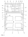
- Fig. 3
- ein schematisches Ablaufdiagramm eines Verfahrens zum Einstellen des Klangortes.
- Fig. 1
- a schematic representation of a motor vehicle with a device for adjusting a sound location of an audio system;
- Fig. 2a-2f
- Views of a combination device comprising a freely programmable display area for illustrating a setting of a sound location; and
- Fig. 3
- a schematic flow diagram of a method for adjusting the sound location.
In
Um eine Einstellung des Klangortes 31 zu ermöglichen, weist die Vorrichtung 23 einen Wertesteller 35 auf, der vorzugsweise als Drehsteller ausgebildet ist. Dieser ist mit der Steuereinheit 25 gekoppelt. Befindet sich die Vorrichtung 23 in einem Einstellmodus für einen der beiden Parameter, die den Klangort 31 festlegen, beispielsweise ein Balancewert und ein Faderwert, so kann mittels des Wertestellers 35 einer der beiden Parameter verändert werden. Bei einer bevorzugten Ausführungsform wird die grafische Darstellung während der Einstellung der Parameter zeitnah angepasst. Als feste Wertstellung wird beispielsweise ein mittels eines Strichs angedeuteter Wert 37 eingestellt, der einen Balancewert 41 (oder in einer anderen Ausführungsform ein Ort optimalen Stereohörens hinsichtlich einer links-rechts-Orientierung) festlegt. Mittels einer Zeitbestimmungseinheit 39 wird eine Ruhe-Zeitspanne ermittelt, die angibt, wie lange keine Veränderung der Drehstellung des als Drehstellers ausgebildeten Wertestellers 35 stattgefunden hat. Überschreitet die Ruhe-Zeitspanne eine vorgegebene Erfassungszeitspanne, so wird die Wertestellung als Balancewert 41 erfasst. Die Vorrichtung wechselt daraufhin automatisch in einen Einstellmodus für den anderen Parameter, hier einen Faderwert. Der Drehsteller wird nun in eine weitere Wertestellung 43 gedreht und nach einer erneuten Ruhe-Zeitspanne, die größer als die Erfassungszeitspanne ist, als Faderwert 45 erfasst. Hierdurch ist ein neuer Klangort 47 festgelegt. Bei einer bevorzugten Ausführungsform wechselt die Vorrichtung, nachdem beide Parameter erfasst worden sind, in einen Menümodus.In order to allow adjustment of the
Bei einer anderen Ausführungsform kann vorgesehen sein, dass der Wertesteller zusätzlich eine Eingabebetätigungshandlung erfassen kann, beispielsweise als Drehdrück- oder Drehziehsteller ausgebildet ist. Anstelle des Ermittelns einer Ruhe-Zeitspanne kann ein Erfassen durch eine Eingabebetätigungshandlung ausgelöst werden.In another embodiment, it may be provided that the value adjuster may additionally detect an input actuation action, for example as a rotary press or rotary puller. Instead of determining a rest period, capture may be triggered by an input actuation action.
In
Wird eine Wertestellung des Wertestellers verändert, beispielsweise eine Balance nach links verstellt, so gelangt man zu der Ansicht nach
In
Für den Fachmann ergibt es sich, dass die mit der Bestimmung der Ruhe-Zeitspanne verknüpften Verfahrensschritte ausgelassen werden können, wenn zum Beenden einer Eingabe eine Eingabebetätigungshandlung erfasst wird. Die Abfrage, ob die Ruhe-Zeitspanne größer als eine Erfassungszeitspanne ist, kann dann durch eine Abfrage ersetzt werden, in der geprüft wird, ob eine Eingabebetätigungshandlung vorliegt. Wieder andere Ausführungsformen können die soeben beschriebenen Ausführungsformen kombinieren, so dass sowohl über eine Eingabebetätigungshandlung als auch über einen Zeitablauf eine automatische Umschaltung zwischen dem einen Einstellmodus und dem anderen Einstellmodus aufgelöst werden kann.It will be apparent to those skilled in the art that the method steps associated with determining the idle time period may be omitted if an input actuation action is detected to terminate an input. The query as to whether the idle time period is greater than a detection period can then be replaced by a query in which it is checked whether an input operation action exists. Still other embodiments may combine the embodiments just described so that automatic switching between one set mode and the other set mode may be resolved via both an input action action and a timing.
Die Darstellung des Innenraums kann bei anderen Ausführungsformen alternativ oder zusätzlich auf einer Anzeigevorrichtung erfolgen, die in einer Mittelkonsole angeordnet ist. Dieses bietet den Vorteil, dass eine Bedienung durch einen Beifahrer erleichtert wird.In other embodiments, the representation of the interior can alternatively or additionally take place on a display device which is arranged in a center console. This offers the advantage that an operation by a passenger is facilitated.
Bei Ausführungsformen, bei denen eine als Touchscreen ausgebildete Anzeigevorrichtung vorhanden ist, kann der Wertesteller als virtuelles Bedienelement ausgebildet sein. Gegebenenfalls kann eine Darstellung des Innenraums zusätzlich auf dieser Anzeigevorrichtung erfolgen. Ebenso ist es möglich, in solchen Fällen eine andere Anzeigevorrichtung, beispielsweise die, die das Kombiinstrument darstellt, für eine Anzeige des Innenraum und die Klangortdarstellung zu verwenden und den virtuellen Wertesteller auf der beispielsweise in der Mittelkonsole angeordneten, als Touchscreen ausgebildeten Anzeigevorrichtung auszubilden.In embodiments in which a display device embodied as a touchscreen is present, the value adjuster can be designed as a virtual operating element. Optionally, a representation of the interior can also be done on this display device. It is also possible to use in such cases, another display device, for example, which represents the instrument cluster, for a display of the interior and the Klangortdarstellung and form the virtual value counter on the example arranged in the center console, designed as a touch screen display device.
Die beschriebenen Ausführungsformen sind lediglich beispielhaft. Weitere Ausführungsformen können die beschriebenen Merkmale in unterschiedlichen Kombinationen verwenden.The described embodiments are merely exemplary. Other embodiments may use the described features in different combinations.
- 11
- Kraftfahrzeugmotor vehicle
- 33
- Innenrauminner space
- 5-115-11
- Sitzeseats
- 13-1913-19
- Lautsprecherspeaker
- 2121
- Audiosystemsound system
- 2323
- Vorrichtung zum Einstellen eines KlangortesDevice for setting a sound location
- 2525
- Steuereinheitcontrol unit
- 2727
- Anzeigevorrichtungdisplay device
- 2929
- Anzeigeflächedisplay area
- 31, 31'31, 31 '
- ursprünglicher Klangortoriginal sound location
- 3333
- Fadenkreuzcrosshairs
- 3535
- Wertestellervalues plate
- 3737
- erste Wertestellungfirst valuation
- 3939
- ZeitbestimmungseinheitTime determination unit
- 4141
- Balancewertbalance value
- 4343
- weitere Wertestellungfurther valuation
- 4545
- Faderwertfader value
- 47, 47'47, 47 '
- neuer Klangortnew sound location
- 5151
- Kombiinstrumentinstrument cluster
- 5353
- DrehzahlanzeigerTachometer
- 5555
- GeschwindigkeitsanzeigerSpeedometer
- 5757
- Mittecenter
- 5959
- frei programmierbare Anzeigeflächefreely programmable display area
- 6161
- Menüeintrag BalanceeinstellungMenu item Balance setting
- 6363
- Menüeintrag FadereinstellungMenu entry Fader setting
- 6464
- weitere Menüeinträgefurther menu entries
- 6565
- Menümenu
- 6767
- Innenrauminner space
- 6969
- KlangortKlangort
- 7171
- Fadenkreuzcrosshairs
- 9191
- Verfahren zur Einstellung eines KlangortesMethod for setting a sound location
- 93-12993-129
- Verfahrensschrittesteps
Claims (10)
eine Anzeigevorrichtung (27),
eine mit der Anzeigevorrichtung (27) gekoppelte Steuereinheit (25), die eine grafische Darstellung auf der Anzeigevorrichtung (27) steuert, und eine mit der Steuereinheit (25) gekoppelte Bedieneinrichtung zum Erfassen von Nutzereingaben, mittels derer zwei Parameter zur Festlegung des Klangort einstellbar sind, wobei vorzugsweise während der Einstellung mittels der Steuereineinheit (25) auf einer Anzeigefläche (29) der Anzeigevorrichtung (27) der Klangort (31', 47') grafisch dargestellt ist,
dadurch gekennzeichnet, dass
die Bedieneinrichtung ein Wertesteller (35) ist und die Steuereinheit (25) ausgebildet ist, nach einem Erfassen einer Einstellung des einen der Parameter in einem Einstellmodus für den einen der Parameter über eine Wertestellung (37) des Wertestellers (35) automatisch in einen Einstellmodus für den anderen der Parameter zu wechseln, der über eine weitere Wertestellung (43) des Wertestellers (35) erfassbar ist.Device (23) for setting a sound location (31, 47) of an audio system (21) in an interior of a motor vehicle (1)
a display device (27),
a control unit (25) coupled to the display device (27), which controls a graphical representation on the display device (27), and an operating device, coupled to the control unit (25), for detecting user inputs by means of which two parameters for determining the sound location can be set wherein, preferably, during adjustment by means of the control unit (25) on a display surface (29) of the display device (27) the sound location (31 ', 47') is shown graphically,
characterized in that
the control device is a value counter (35) and the control unit (25) is adapted to automatically detect a setting of one of the parameters in a setting mode for the one of the parameters via a value position (37) of the value adjuster (35) in a setting mode for to change the other of the parameters, which can be detected via a further value position (43) of the value counter (35).
mittels einer Steuereinheit (25) eine grafische Darstellung einer Anzeigevorrichtung (27) gesteuert wird und bei einer Einstellung des Klangortes (31, 47) zur Festlegung des Klangortes (31, 47) zwei Parameter mittels einer Bedieneinrichtung erfasst werden, wobei vorzugsweise während der Einstellung der Klangort (31', 47') grafisch auf einer Anzeigefläche (29) der Anzeigevorrichtung (27) dargestellt wird,
dadurch gekennzeichnet, dass
die Bedieneinrichtung ein Wertesteller (35) ist und in einem Einstellmodus zur Einstellung des einen der Parameter eine Wertestellung (37) des Wertestellers (35) erfasst wird und automatisch in einen Einstellmodus für den anderen der Parameter gewechselt wird, in dem eine weitere Wertestellung (43) des Wertestellers (35) erfasst wird, um den anderen der Parameter einzustellen.Method (91) for setting a sound location (31, 47) of an audio system (21) in an interior (3) of a motor vehicle (1), in which
a graphical representation of a display device (27) is controlled by means of a control unit (25) and two parameters are detected by means of an operating device when setting the sound location (31, 47) for determining the sound location (31, 47), wherein preferably during the setting of Sound location (31 ', 47') is graphically displayed on a display surface (29) of the display device (27),
characterized in that
the operating device is a value counter (35) and, in a setting mode for setting one of the parameters, a value position (37) of the value counter (35) is detected and automatically changed to a setting mode for the other one of the parameters, in which a further value position (43 ) of the value adjuster (35) is detected to set the other one of the parameters.
Applications Claiming Priority (1)
| Application Number | Priority Date | Filing Date | Title |
|---|---|---|---|
| DE102007026542A DE102007026542A1 (en) | 2007-06-08 | 2007-06-08 | Device and method for adjusting a sound location of an audio system in the interior of a motor vehicle |
Publications (3)
| Publication Number | Publication Date |
|---|---|
| EP2003933A2 true EP2003933A2 (en) | 2008-12-17 |
| EP2003933A3 EP2003933A3 (en) | 2016-05-04 |
| EP2003933B1 EP2003933B1 (en) | 2018-07-25 |
Family
ID=39926422
Family Applications (1)
| Application Number | Title | Priority Date | Filing Date |
|---|---|---|---|
| EP08009673.8A Active EP2003933B1 (en) | 2007-06-08 | 2008-05-28 | Device and method for adjusting a sound position of an audio system in the interior of a motor vehicle |
Country Status (2)
| Country | Link |
|---|---|
| EP (1) | EP2003933B1 (en) |
| DE (1) | DE102007026542A1 (en) |
Citations (1)
| Publication number | Priority date | Publication date | Assignee | Title |
|---|---|---|---|---|
| DE10354492A1 (en) | 2003-11-21 | 2005-06-09 | Volkswagen Ag | Adjustment device for a public address system in a vehicle and corresponding adjustment method |
Family Cites Families (9)
| Publication number | Priority date | Publication date | Assignee | Title |
|---|---|---|---|---|
| US5680468A (en) * | 1995-02-21 | 1997-10-21 | Chrysler Corporation | Methods of and systems for speaker equalization in automotive vehicles having convertible tops |
| DE19608869C2 (en) * | 1996-03-07 | 1998-03-26 | Daimler Benz Ag | Operating system, in particular for components in a motor vehicle |
| DE19861065C2 (en) * | 1998-03-11 | 2001-11-22 | Grundig Ag | Car radio for a vehicle |
| US6760635B1 (en) * | 2000-05-12 | 2004-07-06 | International Business Machines Corporation | Automatic sound reproduction setting adjustment |
| JP2002354600A (en) * | 2001-05-29 | 2002-12-06 | Pioneer Electronic Corp | Acoustic device |
| KR100510708B1 (en) * | 2003-04-09 | 2005-08-26 | 현대모비스 주식회사 | Auto volume controlling device tuned by car speed and its operating method |
| DE10360664A1 (en) * | 2003-12-23 | 2005-07-28 | Daimlerchrysler Ag | Operating system for a motor vehicle |
| DE10360655A1 (en) * | 2003-12-23 | 2005-07-21 | Daimlerchrysler Ag | Operating system for a vehicle |
| US7373229B2 (en) * | 2004-07-29 | 2008-05-13 | Gm Global Technology Operations, Inc. | Multifunction control system |
-
2007
- 2007-06-08 DE DE102007026542A patent/DE102007026542A1/en not_active Withdrawn
-
2008
- 2008-05-28 EP EP08009673.8A patent/EP2003933B1/en active Active
Patent Citations (1)
| Publication number | Priority date | Publication date | Assignee | Title |
|---|---|---|---|---|
| DE10354492A1 (en) | 2003-11-21 | 2005-06-09 | Volkswagen Ag | Adjustment device for a public address system in a vehicle and corresponding adjustment method |
Also Published As
| Publication number | Publication date |
|---|---|
| DE102007026542A1 (en) | 2008-12-11 |
| EP2003933A3 (en) | 2016-05-04 |
| EP2003933B1 (en) | 2018-07-25 |
Similar Documents
| Publication | Publication Date | Title |
|---|---|---|
| EP2633381B1 (en) | Operating device for operating at least one electric device | |
| DE112014006432T5 (en) | A method and apparatus for providing a personalized operator control for a vehicle | |
| EP3243688B1 (en) | Method and device for the allocation of control commands in a vehicle, as well as vehicle | |
| DE102007029598A1 (en) | Vehicle interface with armrest control arrangement | |
| DE19735977C2 (en) | Operating and control unit for a heating, ventilation and / or air conditioning system and for the seat heating and / or seat ventilation system | |
| DE102012214295A1 (en) | Operating device at least for setting a desired seating position in a motor vehicle | |
| DE102010062317A1 (en) | Positioning device for adjusting seating position for adjustable vehicle seat, has driving unit to generate control signal for adjusting seat adjustable components based on parameter set selected according to user body height input | |
| EP3154813A1 (en) | Switchable operating device for a motor vehicle | |
| DE102004040829B4 (en) | Operating device for motor vehicles | |
| DE102008061989B4 (en) | Method and device for controlling an optical and / or acoustic output in a vehicle | |
| EP2003933B1 (en) | Device and method for adjusting a sound position of an audio system in the interior of a motor vehicle | |
| DE102020100062A1 (en) | Control unit and method for setting a parameter of a functional unit of a motor vehicle | |
| DE102017200197A1 (en) | Control unit for an in-vehicle system, in-vehicle system and vehicle | |
| DE102014018397A1 (en) | Operating unit for a motor vehicle for operating a plurality of different functions | |
| EP3188922B1 (en) | Control device and method for controlling functions in a vehicle, in particular a motor vehicle | |
| DE102012020855A1 (en) | Method for adjusting setting arrangement of seat of motor vehicle i.e. passenger car, involves playing seat position video by display device for vehicle training occupant to adjust seat setting in cooperation with seat position module | |
| DE10058360B4 (en) | Air conditioning control for a vehicle | |
| DE102009049111A1 (en) | Method for controlling information indication in vehicle, involves forming display portion within round instrument and another display portion outside round instrument on display area of former display portion | |
| DE102005034708B3 (en) | Operator system e.g., for motor vehicles, has operator device with elements for individual functions | |
| DE102007004660A1 (en) | Haptic operating unit for use in modern motor vehicle, has two operating components, where form of operating unit is changed by operating one of operating components and then control signal is produced | |
| DE102004053950A1 (en) | Indicator device for control unit of motor vehicle, has controlling and monitoring menu that automatically displays if contact of control switch of apparatus e.g. radio of vehicle, is identified | |
| WO2017125326A1 (en) | Adaptive operator control device for a motor vehicle | |
| DE102007012594B4 (en) | Device and method for operating a motor vehicle | |
| DE102016015753A1 (en) | Method for operating an operating device in a motor vehicle and operating device and motor vehicle | |
| DE102018216662A1 (en) | Dashboard layout, procedure and use |
Legal Events
| Date | Code | Title | Description |
|---|---|---|---|
| PUAI | Public reference made under article 153(3) epc to a published international application that has entered the european phase |
Free format text: ORIGINAL CODE: 0009012 |
|
| AK | Designated contracting states |
Kind code of ref document: A2 Designated state(s): AT BE BG CH CY CZ DE DK EE ES FI FR GB GR HR HU IE IS IT LI LT LU LV MC MT NL NO PL PT RO SE SI SK TR |
|
| AX | Request for extension of the european patent |
Extension state: AL BA MK RS |
|
| RAP1 | Party data changed (applicant data changed or rights of an application transferred) |
Owner name: VOLKSWAGEN AKTIENGESELLSCHAFT |
|
| PUAL | Search report despatched |
Free format text: ORIGINAL CODE: 0009013 |
|
| AK | Designated contracting states |
Kind code of ref document: A3 Designated state(s): AT BE BG CH CY CZ DE DK EE ES FI FR GB GR HR HU IE IS IT LI LT LU LV MC MT NL NO PL PT RO SE SI SK TR |
|
| AX | Request for extension of the european patent |
Extension state: AL BA MK RS |
|
| RIC1 | Information provided on ipc code assigned before grant |
Ipc: H04S 7/00 20060101AFI20160330BHEP |
|
| STAA | Information on the status of an ep patent application or granted ep patent |
Free format text: STATUS: REQUEST FOR EXAMINATION WAS MADE |
|
| 17P | Request for examination filed |
Effective date: 20161104 |
|
| RBV | Designated contracting states (corrected) |
Designated state(s): AT BE BG CH CY CZ DE DK EE ES FI FR GB GR HR HU IE IS IT LI LT LU LV MC MT NL NO PL PT RO SE SI SK TR |
|
| AKX | Designation fees paid |
Designated state(s): AT BE BG CH CY CZ DE DK EE ES FI FR GB GR HR HU IE IS IT LI LT LU LV MC MT NL NO PL PT RO SE SI SK TR |
|
| AXX | Extension fees paid |
Extension state: AL Extension state: RS Extension state: MK Extension state: BA |
|
| STAA | Information on the status of an ep patent application or granted ep patent |
Free format text: STATUS: EXAMINATION IS IN PROGRESS |
|
| 17Q | First examination report despatched |
Effective date: 20170126 |
|
| GRAP | Despatch of communication of intention to grant a patent |
Free format text: ORIGINAL CODE: EPIDOSNIGR1 |
|
| STAA | Information on the status of an ep patent application or granted ep patent |
Free format text: STATUS: GRANT OF PATENT IS INTENDED |
|
| INTG | Intention to grant announced |
Effective date: 20180507 |
|
| GRAS | Grant fee paid |
Free format text: ORIGINAL CODE: EPIDOSNIGR3 |
|
| GRAA | (expected) grant |
Free format text: ORIGINAL CODE: 0009210 |
|
| STAA | Information on the status of an ep patent application or granted ep patent |
Free format text: STATUS: THE PATENT HAS BEEN GRANTED |
|
| AK | Designated contracting states |
Kind code of ref document: B1 Designated state(s): AT BE BG CH CY CZ DE DK EE ES FI FR GB GR HR HU IE IS IT LI LT LU LV MC MT NL NO PL PT RO SE SI SK TR |
|
| REG | Reference to a national code |
Ref country code: GB Ref legal event code: FG4D Free format text: NOT ENGLISH |
|
| REG | Reference to a national code |
Ref country code: CH Ref legal event code: EP |
|
| REG | Reference to a national code |
Ref country code: AT Ref legal event code: REF Ref document number: 1023075 Country of ref document: AT Kind code of ref document: T Effective date: 20180815 |
|
| REG | Reference to a national code |
Ref country code: DE Ref legal event code: R096 Ref document number: 502008016201 Country of ref document: DE |
|
| REG | Reference to a national code |
Ref country code: IE Ref legal event code: FG4D Free format text: LANGUAGE OF EP DOCUMENT: GERMAN |
|
| REG | Reference to a national code |
Ref country code: NL Ref legal event code: MP Effective date: 20180725 |
|
| REG | Reference to a national code |
Ref country code: LT Ref legal event code: MG4D |
|
| PG25 | Lapsed in a contracting state [announced via postgrant information from national office to epo] |
Ref country code: NL Free format text: LAPSE BECAUSE OF FAILURE TO SUBMIT A TRANSLATION OF THE DESCRIPTION OR TO PAY THE FEE WITHIN THE PRESCRIBED TIME-LIMIT Effective date: 20180725 |
|
| PG25 | Lapsed in a contracting state [announced via postgrant information from national office to epo] |
Ref country code: PL Free format text: LAPSE BECAUSE OF FAILURE TO SUBMIT A TRANSLATION OF THE DESCRIPTION OR TO PAY THE FEE WITHIN THE PRESCRIBED TIME-LIMIT Effective date: 20180725 Ref country code: IS Free format text: LAPSE BECAUSE OF FAILURE TO SUBMIT A TRANSLATION OF THE DESCRIPTION OR TO PAY THE FEE WITHIN THE PRESCRIBED TIME-LIMIT Effective date: 20181125 Ref country code: BG Free format text: LAPSE BECAUSE OF FAILURE TO SUBMIT A TRANSLATION OF THE DESCRIPTION OR TO PAY THE FEE WITHIN THE PRESCRIBED TIME-LIMIT Effective date: 20181025 Ref country code: LT Free format text: LAPSE BECAUSE OF FAILURE TO SUBMIT A TRANSLATION OF THE DESCRIPTION OR TO PAY THE FEE WITHIN THE PRESCRIBED TIME-LIMIT Effective date: 20180725 Ref country code: NO Free format text: LAPSE BECAUSE OF FAILURE TO SUBMIT A TRANSLATION OF THE DESCRIPTION OR TO PAY THE FEE WITHIN THE PRESCRIBED TIME-LIMIT Effective date: 20181025 Ref country code: SE Free format text: LAPSE BECAUSE OF FAILURE TO SUBMIT A TRANSLATION OF THE DESCRIPTION OR TO PAY THE FEE WITHIN THE PRESCRIBED TIME-LIMIT Effective date: 20180725 Ref country code: FI Free format text: LAPSE BECAUSE OF FAILURE TO SUBMIT A TRANSLATION OF THE DESCRIPTION OR TO PAY THE FEE WITHIN THE PRESCRIBED TIME-LIMIT Effective date: 20180725 Ref country code: GR Free format text: LAPSE BECAUSE OF FAILURE TO SUBMIT A TRANSLATION OF THE DESCRIPTION OR TO PAY THE FEE WITHIN THE PRESCRIBED TIME-LIMIT Effective date: 20181026 |
|
| PG25 | Lapsed in a contracting state [announced via postgrant information from national office to epo] |
Ref country code: HR Free format text: LAPSE BECAUSE OF FAILURE TO SUBMIT A TRANSLATION OF THE DESCRIPTION OR TO PAY THE FEE WITHIN THE PRESCRIBED TIME-LIMIT Effective date: 20180725 Ref country code: ES Free format text: LAPSE BECAUSE OF FAILURE TO SUBMIT A TRANSLATION OF THE DESCRIPTION OR TO PAY THE FEE WITHIN THE PRESCRIBED TIME-LIMIT Effective date: 20180725 Ref country code: LV Free format text: LAPSE BECAUSE OF FAILURE TO SUBMIT A TRANSLATION OF THE DESCRIPTION OR TO PAY THE FEE WITHIN THE PRESCRIBED TIME-LIMIT Effective date: 20180725 |
|
| REG | Reference to a national code |
Ref country code: DE Ref legal event code: R097 Ref document number: 502008016201 Country of ref document: DE |
|
| PG25 | Lapsed in a contracting state [announced via postgrant information from national office to epo] |
Ref country code: CZ Free format text: LAPSE BECAUSE OF FAILURE TO SUBMIT A TRANSLATION OF THE DESCRIPTION OR TO PAY THE FEE WITHIN THE PRESCRIBED TIME-LIMIT Effective date: 20180725 Ref country code: RO Free format text: LAPSE BECAUSE OF FAILURE TO SUBMIT A TRANSLATION OF THE DESCRIPTION OR TO PAY THE FEE WITHIN THE PRESCRIBED TIME-LIMIT Effective date: 20180725 Ref country code: IT Free format text: LAPSE BECAUSE OF FAILURE TO SUBMIT A TRANSLATION OF THE DESCRIPTION OR TO PAY THE FEE WITHIN THE PRESCRIBED TIME-LIMIT Effective date: 20180725 Ref country code: EE Free format text: LAPSE BECAUSE OF FAILURE TO SUBMIT A TRANSLATION OF THE DESCRIPTION OR TO PAY THE FEE WITHIN THE PRESCRIBED TIME-LIMIT Effective date: 20180725 |
|
| PG25 | Lapsed in a contracting state [announced via postgrant information from national office to epo] |
Ref country code: SK Free format text: LAPSE BECAUSE OF FAILURE TO SUBMIT A TRANSLATION OF THE DESCRIPTION OR TO PAY THE FEE WITHIN THE PRESCRIBED TIME-LIMIT Effective date: 20180725 Ref country code: DK Free format text: LAPSE BECAUSE OF FAILURE TO SUBMIT A TRANSLATION OF THE DESCRIPTION OR TO PAY THE FEE WITHIN THE PRESCRIBED TIME-LIMIT Effective date: 20180725 |
|
| PLBE | No opposition filed within time limit |
Free format text: ORIGINAL CODE: 0009261 |
|
| STAA | Information on the status of an ep patent application or granted ep patent |
Free format text: STATUS: NO OPPOSITION FILED WITHIN TIME LIMIT |
|
| 26N | No opposition filed |
Effective date: 20190426 |
|
| PG25 | Lapsed in a contracting state [announced via postgrant information from national office to epo] |
Ref country code: SI Free format text: LAPSE BECAUSE OF FAILURE TO SUBMIT A TRANSLATION OF THE DESCRIPTION OR TO PAY THE FEE WITHIN THE PRESCRIBED TIME-LIMIT Effective date: 20180725 |
|
| REG | Reference to a national code |
Ref country code: CH Ref legal event code: PL |
|
| PG25 | Lapsed in a contracting state [announced via postgrant information from national office to epo] |
Ref country code: LI Free format text: LAPSE BECAUSE OF NON-PAYMENT OF DUE FEES Effective date: 20190531 Ref country code: CH Free format text: LAPSE BECAUSE OF NON-PAYMENT OF DUE FEES Effective date: 20190531 Ref country code: MC Free format text: LAPSE BECAUSE OF FAILURE TO SUBMIT A TRANSLATION OF THE DESCRIPTION OR TO PAY THE FEE WITHIN THE PRESCRIBED TIME-LIMIT Effective date: 20180725 |
|
| REG | Reference to a national code |
Ref country code: BE Ref legal event code: MM Effective date: 20190531 |
|
| PG25 | Lapsed in a contracting state [announced via postgrant information from national office to epo] |
Ref country code: LU Free format text: LAPSE BECAUSE OF NON-PAYMENT OF DUE FEES Effective date: 20190528 |
|
| PG25 | Lapsed in a contracting state [announced via postgrant information from national office to epo] |
Ref country code: TR Free format text: LAPSE BECAUSE OF FAILURE TO SUBMIT A TRANSLATION OF THE DESCRIPTION OR TO PAY THE FEE WITHIN THE PRESCRIBED TIME-LIMIT Effective date: 20180725 |
|
| PG25 | Lapsed in a contracting state [announced via postgrant information from national office to epo] |
Ref country code: IE Free format text: LAPSE BECAUSE OF NON-PAYMENT OF DUE FEES Effective date: 20190528 |
|
| PG25 | Lapsed in a contracting state [announced via postgrant information from national office to epo] |
Ref country code: BE Free format text: LAPSE BECAUSE OF NON-PAYMENT OF DUE FEES Effective date: 20190531 |
|
| PG25 | Lapsed in a contracting state [announced via postgrant information from national office to epo] |
Ref country code: PT Free format text: LAPSE BECAUSE OF FAILURE TO SUBMIT A TRANSLATION OF THE DESCRIPTION OR TO PAY THE FEE WITHIN THE PRESCRIBED TIME-LIMIT Effective date: 20181125 |
|
| REG | Reference to a national code |
Ref country code: AT Ref legal event code: MM01 Ref document number: 1023075 Country of ref document: AT Kind code of ref document: T Effective date: 20190528 |
|
| PG25 | Lapsed in a contracting state [announced via postgrant information from national office to epo] |
Ref country code: AT Free format text: LAPSE BECAUSE OF NON-PAYMENT OF DUE FEES Effective date: 20190528 |
|
| PG25 | Lapsed in a contracting state [announced via postgrant information from national office to epo] |
Ref country code: CY Free format text: LAPSE BECAUSE OF FAILURE TO SUBMIT A TRANSLATION OF THE DESCRIPTION OR TO PAY THE FEE WITHIN THE PRESCRIBED TIME-LIMIT Effective date: 20180725 |
|
| PG25 | Lapsed in a contracting state [announced via postgrant information from national office to epo] |
Ref country code: HU Free format text: LAPSE BECAUSE OF FAILURE TO SUBMIT A TRANSLATION OF THE DESCRIPTION OR TO PAY THE FEE WITHIN THE PRESCRIBED TIME-LIMIT; INVALID AB INITIO Effective date: 20080528 Ref country code: MT Free format text: LAPSE BECAUSE OF FAILURE TO SUBMIT A TRANSLATION OF THE DESCRIPTION OR TO PAY THE FEE WITHIN THE PRESCRIBED TIME-LIMIT Effective date: 20180725 |
|
| P01 | Opt-out of the competence of the unified patent court (upc) registered |
Effective date: 20230523 |
|
| PGFP | Annual fee paid to national office [announced via postgrant information from national office to epo] |
Ref country code: FR Payment date: 20230523 Year of fee payment: 16 Ref country code: DE Payment date: 20230531 Year of fee payment: 16 |
|
| PGFP | Annual fee paid to national office [announced via postgrant information from national office to epo] |
Ref country code: GB Payment date: 20230523 Year of fee payment: 16 |