EP2003863A1 - Handapparat für eine Breitbandtelekommunikationsanlage - Google Patents
Handapparat für eine Breitbandtelekommunikationsanlage Download PDFInfo
- Publication number
- EP2003863A1 EP2003863A1 EP07019896A EP07019896A EP2003863A1 EP 2003863 A1 EP2003863 A1 EP 2003863A1 EP 07019896 A EP07019896 A EP 07019896A EP 07019896 A EP07019896 A EP 07019896A EP 2003863 A1 EP2003863 A1 EP 2003863A1
- Authority
- EP
- European Patent Office
- Prior art keywords
- handset
- coupling
- coupling slots
- volume
- joining edge
- Prior art date
- Legal status (The legal status is an assumption and is not a legal conclusion. Google has not performed a legal analysis and makes no representation as to the accuracy of the status listed.)
- Ceased
Links
Images
Classifications
-
- H—ELECTRICITY
- H04—ELECTRIC COMMUNICATION TECHNIQUE
- H04M—TELEPHONIC COMMUNICATION
- H04M1/00—Substation equipment, e.g. for use by subscribers
- H04M1/02—Constructional features of telephone sets
- H04M1/03—Constructional features of telephone transmitters or receivers, e.g. telephone hand-sets
- H04M1/035—Improving the acoustic characteristics by means of constructional features of the housing, e.g. ribs, walls, resonating chambers or cavities
-
- H—ELECTRICITY
- H04—ELECTRIC COMMUNICATION TECHNIQUE
- H04M—TELEPHONIC COMMUNICATION
- H04M1/00—Substation equipment, e.g. for use by subscribers
- H04M1/02—Constructional features of telephone sets
- H04M1/0202—Portable telephone sets, e.g. cordless phones, mobile phones or bar type handsets
- H04M1/0249—Details of the mechanical connection between the housing parts or relating to the method of assembly
-
- H—ELECTRICITY
- H04—ELECTRIC COMMUNICATION TECHNIQUE
- H04M—TELEPHONIC COMMUNICATION
- H04M1/00—Substation equipment, e.g. for use by subscribers
- H04M1/60—Substation equipment, e.g. for use by subscribers including speech amplifiers
- H04M1/6033—Substation equipment, e.g. for use by subscribers including speech amplifiers for providing handsfree use or a loudspeaker mode in telephone sets
- H04M1/6041—Portable telephones adapted for handsfree use
Definitions
- the invention relates to a handset for a Breitbandtelekommunikationsstrom, the housing is composed to form a joining edge of an upper and a lower shell
- Telephone terminals that are connected to a broadband telecommunications system typically have handsets that are directly or wirelessly connected that can send and receive voice messages to a user.
- such handsets usually have built-in microphones for receiving the voice message and speakers for the transmission of such a voice message to the user, which are arranged in a common housing of the handset.
- this housing is usually to form a so-called joint edge of an upper and lower shell, that is essentially composed of two housing halves.
- a resonance volume is usually provided in the interior of the handset in the region of the loudspeaker.
- the acoustic signal of the voice message in the corresponding frequencies is amplified by resonance and thus can be taken more clearly perceived by the user.
- the limited available in handsets due to the design resonant volume therefore also limits the frequency range, which is amplified by the resonance, and thus the acoustically perceptible transmission quality of the system.
- the lower limit of the thus easily transferable signal frequencies is therefore at the usual dimension of handsets at about 400 Hz.
- handset conventional design are provided with a number of coupling slots. These coupling slots connect the resonance volume in the interior of the handset with the free field outside the handset. This coupling of the resonance volume to the outer air space makes it possible to enlarge it in the simplest way. This ensures that even the frequency range below 400 Hz can be amplified reproduced or transmitted and thus a particularly good sound of the voice message can be generated by the speaker.
- the coupling slots are usually arranged on the back of the handset.
- handsets can alternatively be placed completely open at the back to allow a maximum coupling of the free field.
- an amplification of the frequency range down to 100 Hz or even down to 20 Hz can be achieved.
- attaching apertures to the back of the handset not only limits the designer's freedom in optical design of the handsets as desired, but also the convenience and privacy of operation of such handsets for the broadband telecommunications equipment.
- the openings on the back of the handset and the unwanted non-directional radiation of the sound thus occurring can thus cause considerable damage to the sound leakage into the free field. This leads, for example, in installations in call centers to increased noise pollution and unwanted listening to third parties in confidential discussions.
- the invention is therefore an object of the invention to provide a handset for broadband telecommunications of the above type, in which a reliable Coupling of the resonance volume is guaranteed to the free field at particularly low retained sound leakage.
- This object is achieved by the joining edge is provided with a number of coupling slots.
- the invention is based on the consideration that, for the use of a handset for broadband telecommunications, ie with a particularly wide frequency spectrum during transmission, in this case the outside field should in any case be acoustically coupled to the resonance volume in the interior of the handset.
- suitable openings through which a sound conducting connection of the resonant volume is made with the outer field is to be maintained in any case.
- these openings should be applied to positions of the handset that do not promote sound leakage across the back of the handset. Since this requirement of the joining edge of the handset, which is formed when mating a top and bottom shell, is easily fulfilled anyway, the coupling slots, which couple the outside field acoustically with a cavity in the interior of the handset, moved into this joining edge.
- these coupling slots in the vicinity of the speaker, ie at the top of the handset, arranged, since they are then in direct communication with the resonance volume in the interior of the handset.
- the risk is kept particularly low, that the coupling slots are covered in the joining edge by, for example, the hands of the user and thus the acoustic coupling of the outer field is affected to the resonance volume in the interior of the handset.
- the passage area of the coupling slots is preferably selected such that the requirements for the frequency spectrum to be amplified are satisfied by the coupling to the free field.
- the width of the coupling slots extends preferably over the entire width of the joining edge, so that it is fully-circumferentially used for the coupling slots.
- the length of the coupling slots is preferably adapted to the required passage area.
- the coupling slots are arranged in a further advantageous embodiment symmetrically with respect to an axis of symmetry of the handset. This ensures that the type of use, that is, for example, whether the handset is held by a left hand or by a right hand, the functionality of the coupling slots influenced only slightly.
- the advantages achieved by the invention are, in particular, that the leakage sound is kept particularly low by the arrangement of the coupling slots in the joining edge of the housing, wherein at the same time the coupling of the acoustic freewheel to the resonant volume in the interior of the handset is still ensured. Especially the unwanted emission of sound waves through openings on the back of the handsets and the consequent lack of privacy is thus reduced in a particularly simple manner. Furthermore, by the use of openings as coupling slots in the joining edge which may be important for the manufacturers of such handsets important designerische freedom is not significantly limited, and visually undesirable blemish on both sides of the manufacturer and on the part of the buyer are avoided.
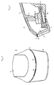
- the handset 1 according to Fig. 1 is part of a broadband telecommunication system connected to a plurality of terminals and intended for the transmission and reception of voice messages as required.
- the handset 1 is directly or wirelessly connected to an associated terminal.
- the housing of the handset 1 is composed of an upper shell 2 and a lower shell 4, which are fastened to each other via a plug connection in the interior of the handset 1.
- the lower shell 4 of the handset 1 includes in per se conventional design, among other outlet openings for a arranged inside the handset 1 microphone and a speaker unit, which are arranged spatially separated from each other.
- a hollow body is arranged in the interior of the handset, which serves as a resonance volume for the emitted sound waves.
- This resonant volume amplifies the exiting sound waves and improves the sound of the voice message. Since the high frequencies of the sound waves are preferably amplified by the structurally limited volume, play a role for a high sound quality and faithful reproduction in the transmission of voice messages but also the lower frequencies, a number of coupling slots 8 are arranged on the handset.
- Coupling slots 8 are mounted in the conventional design, however, on the back of the handset 1 and therefore pose a risk in privacy, since sound waves can pass undesirable through the coupling slots 8 on the back of the handset 1 in the outer free field.
- the handset gem. Fig. 1 but just specifically designed to be kept particularly low despite a sufficiently high acoustic coupling of the resonant volume to the exterior of such sound leaks.
- the handset 1 gem. Fig. 1 the coupling slots 8 specifically arranged in the joining edge 6 of the housing.
- the coupling slots 8 are optically hidden by the arrangement in the joining edge 6 and thus give the developers a particularly high designerische freedom.
- the in the Fig. 1 Coupling slots 8 shown are arranged symmetrically with respect to the longitudinal axis, ie the axis extending from the center of the bottom to the center of the top through the geometric center of the handset 1. As a result, the flexibility in the use of such handsets 1 is increased.
- the coupling slots 8 are limited in width by the width of the joining edge, but can be adjusted in length for optimal coupling of the acoustic free field. With an average joining edge of about 2 mm, this results in a preferred length of the coupling slots of about 12 mm. This allows a gain of frequencies down to 100 Hz can be achieved.
- FIG. 2 A longitudinal section through the top of the handset 1 for broadband telecommunications is in Fig. 2 shown.
- a loudspeaker unit 10 is placed in a loudspeaker socket 12 for the reception of incoming acoustic signals.
- the speaker unit 10 is pressed by the mating of the upper shell 2 and the lower shell 4 of the handset 1 by means of a molded on the upper shell 2 and directed into the interior of the handset holding web 14 in the speaker socket and held in it.
- the joining edge 6 formed when the upper and lower shells 4 are plugged together comprises a coupling slot 8 which connects a rear volume 16 delimited by the upper and lower shells 4 to the outer space.
- the back space volume 16 serves the loudspeaker unit 10 during operation of the handset 1 as a resonance volume for amplifying the sound waves emitted by the outlet openings 18.
- the targeted arrangement of the coupling slots 8 in the joining edge 6, the acoustic free field is coupled to the back space volume and thereby increases the resonance volume.
Landscapes
- Engineering & Computer Science (AREA)
- Signal Processing (AREA)
- Physics & Mathematics (AREA)
- Acoustics & Sound (AREA)
- Telephone Set Structure (AREA)
Abstract
Description
- Die Erfindung bezieht sich auf einen Handapparat für eine Breitbandtelekommunikationsanlage, dessen Gehäuse unter Bildung einer Fügekante aus einer Ober- und einer Unterschale zusammengesetzt ist
- Telefonendgeräte, die an eine Breitbandtelekömmunikationsanlage angeschlossen sind, verfügen üblicherweise über direkt oder kabellos verbundene Handapparate, die Sprachnachrichten an einen Benutzer senden und von diesem empfangen werden können. Hierzu verfügen solche Handapparate in der Regel über eingebaute Mikrofone zur Aufnahme der Sprachnachricht und über Lautsprecher zur Übermittlung einer solchen Sprachnachricht an den Benutzer, die in einem gemeinsamen Gehäuse des Handapparats angeordnet sind. Aus produktions-technischen Gründen ist dieses Gehäuse üblicherweise unter Bildung einer so genannten Fügekante aus einer Ober- und Unterschale, also im wesentlichen aus zwei Gehäusehälften, zusammengesetzt.
- Um bei der Übermittlung einer Sprachnachricht an den Benutzer ein besonders gutes Klangspektrum zu erhalten, ist im Inneren des Handapparates im Bereich des Lautsprechers üblicherweise ein Resonanzvolumen vorgesehen. In Abhängigkeit des zur Verfügung stehenden Volumens und insbesondere von dessen räumlicher Ausdehnung wird nämlich das akustische Signal der Sprachmitteilung in den entsprechenden Frequenzen durch Resonanz verstärkt und kann somit für den Benutzer deutlicher wahr genommen werden. Das in Handapparaten aufgrund der Bauart nur begrenzt zur Verfügung stehende Resonanzvolumen beschränkt daher auch den Frequenzbereich, der durch die Resonanz verstärkt wird, und somit auch die akustisch wahrnehmbare Übertragungsqualität des Systems. Die untere Grenze der auf diese Weise noch gut übertragbaren Signalfrequenzen liegt daher bei der üblichen Dimension von Handapparaten bei etwa 400 Hz.
- Um jedoch für eine bessere Hör- und Übertragungsqualität für das menschliche Gehör insgesamt wahrnehmbare Frequenzspektrum, das sich auf der Tieffrequenzseite bis hin zu Frequenzen von ca. 1 Hz erstreckt, übertragungsseitig besonders gut abzudecken, sind Handapparate üblicher Bauweise mit einer Anzahl von Koppelschlitzen versehen. Diese Koppelschlitze verbinden das Resonanzvolumen im Inneren des Handapparates mit dem Freifeld außerhalb des Handapparates. Diese Ankopplung des Resonanzvolumens an den äußeren Luftraum ermöglicht es, dieses auf einfachste Weise zu vergrößern. Hierdurch wird erreicht, dass auch der Frequenzbereich unter 400 Hz verstärkt wiedergegeben oder übertragen werden kann und somit ein besonders guter Klang der Sprachmitteilung durch den Lautsprecher erzeugt werden kann. Für eine zuverlässige Freifeldankopplung sind die Koppelschlitze üblicherweise an der Rückseite des Handapparates angeordnet. Je nach Verwendungszweck können Handapparate rückseitig alternativ auch sogar komplett offen gelegt werden, um eine maximale Ankopplung des Freifeldes zu ermöglichen. Je nach Ausarbeitung der Koppelschlitze und der durch sie erzielten Ankopplung ist dabei eine Verstärkung des Frequenzbereiches bis hinab zu 100 Hz oder auch bis hinab zu 20 Hz erreichbar.
- Das Anbringen von Öffnungen an der Rückseite des Handapparates schränkt jedoch nicht nur die an sich erwünschte designerische Freiheit bei der optischen Gestaltung der Handapparate, sondern auch den Komfort und die Abhörsicherheit beim Betrieb solcher Handapparate für die Breitbandtelekommunikationsanlagen ein. Gerade im Hinblick auf die Abhörsicherheit können die Öffnungen an der Rückseite des Handapparates und die damit eintretende unerwünschte ungerichtete Abstrahlung des Schalls also die Schallleckage ins Freifeld erhebliche Einschränkungen bedingen. Dies führt beispielsweise bei Anlagen in Call-Centern zu einer erhöhten Lärmbelästigung und zu unerwünschtem Mithören dritter Personen bei vertraulichen Gesprächen.
- Der Erfindung liegt daher die Aufgabe zugrunde, einen Handapparat für die Breitbandtelekommunikation der oben genannten Art anzugeben, bei dem eine zuverlässige Ankopplung des Resonanzvolumens an das Freifeld bei besonders gering gehaltener Schallleckage gewährleistet ist.
- Diese Aufgabe wird erfindungsgemäß gelöst, indem die Fügekante mit einer Anzahl von Koppelschlitzen versehen ist.
- Die Erfindung geht dabei von der Überlegung aus, dass für die Nutzung eines Handapparates für die Breitbandtelekommunikation, also mit besonders breitem Frequenzspektrum bei der Übertragung, bei diesem das Außenfeld in jedem Fall akustisch an das Resonanzvolumen im Inneren des Handapparates angekoppelt sein sollte. Hierzu sollten bei der Auslegung des Handapparats geeignete Öffnungen, durch die eine schallleitende Verbindung des Resonanzvolumens mit dem Außenfeld hergestellt wird in jedem Fall beibehalten werden. Zur Begrenzung von Schallleckage über die Rückseite des Handapparates sollten diese Öffnungen aber an Positionen des Handapparates angebracht werden, die keine Schallleckage über die Rückseite des Handapparates fördern. Da diese Anforderung von der Fügekante des Handapparates, die beim Zusammenstecken einer Ober- und Unter-schale gebildet wird, zwanglos ohnehin erfüllt wird, werden die Koppelschlitze, die das Außenfeld akustisch mit einem Hohlraum im Inneren des Handapparates ankoppeln, in diese Fügekante hinein verlagert.
- In bevorzugter Ausführung sind diese Koppelschlitze in der Nähe des Lautsprechers, also an der Oberseite des Handapparates, angeordnet, da sie dann mit dem Resonanzvolumen im Inneren des Handapparates in direkter Verbindung stehen. Zusätzlich wird dadurch die Gefahr besonders gering gehalten, dass die Koppelschlitze in der Fügekante durch beispielsweise die Hände des Benutzers abgedeckt werden und somit die akustische Ankoppelung des Außenfeldes an das Resonanzvolumen im Inneren des Handapparates beeinträchtigt ist.
- Die Durchtrittsfläche der Koppelschlitze ist vorzugsweise so gewählt, dass die Anforderungen an das zu verstärkende Frequenzspektrum durch die Ankopplung an das Freifeld erfüllt werden. Die Breite der Koppelschlitze erstreckt sich dabei vorzugsweise über die gesamte Breite der Fügekante, so dass diese voll-umfänglich für die Koppelschlitze genutzt ist. Die Länge der Koppelschlitze ist dabei vorzugsweise an die benötigte Durchtrittsfläche angepasst.
- Um in einfachster Weise den Produktionsaufwand bei der Herstellung der für den Handapparat verwendeten Ober- und Unterschale besonders zu verringern und die Flexibilität zu erhöhen, sind die Koppelschlitze in weiterer vorteilhafter Ausgestaltung symmetrisch bezüglich einer Symmetrieachse des Handapparates angeordnet. Hierdurch wird erreicht, dass die Art der Benutzung, also beispielsweise ob der Handapparat von einer linken Hand oder von einer rechten Hand gehalten wird, die Funktionalität der Koppelschlitze nur gering beeinflusst.
- Die mit der Erfindung erzielten Vorteile bestehen insbesondere darin, dass durch die Anordnung der Koppelschlitze in die Fügekante des Gehäuses der Leckageschall besonders gering gehalten wird, wobei gleichzeitig die Ankopplung des akustischen Freifeldes an das Resonanzvolumen im Inneren des Handapparates weiterhin sichergestellt wird. Gerade die unerwünschte Aussendung von Schallwellen durch Öffnungen an der Rückseite der Handapparate und der dadurch bedingte Mangel in der Abhörsicherheit ist somit auf besonders einfache Weise vermindert. Weiterhin ist durch die Verwendung von Öffnungen als Koppelschlitze in der Fügekante die für die Hersteller derartiger Handapparate möglicherweise wichtige designerische Freiheit nicht wesentlich eingeschränkt, und optisch unerwünschte Makel sowohl auf Seiten der Hersteller als auch auf Seiten der Käufer sind vermieden.
- Ein Ausführungsbeispiel der Erfindung wird anhand einer Zeichnung näher erläutert. Darin zeigen:
- Fig. 1
- die Oberseite eines Handapparates für die Breitbandtelekommunikation,
- Fig. 2
- einen Längsschnitt durch die Oberseite eines Handapparates für die Breitbandtelekommunikation
- Gleiche Teile sind in beiden Figuren mit denselben Bezugszeichen versehen.
- Der Handapparat 1 gemäß
Fig. 1 ist Teil einer mit einer Mehrzahl von Endgeräten verbundenen Breitbandtelekommunikationsanlage und zur bedarfsweisen Übermittlung und Aufnahme von Sprachmitteilungen vorgesehen. Der Handapparat 1 ist direkt oder kabellos mit einem zugeordneten Endgerät verbunden. Wie in der Darstellung nachFig. 1 erkennbar ist, ist das Gehäuse des Handapparates 1 aus einer Oberschale 2 und aus einer Unterschale 4 zusammengesetzt, die über eine Steckverbindung im Inneren des Handapparates 1 aneinander befestigt sind. Eine schmale Fügekante 6, die durch das Zusammenstecken der Ober- 2 und Unterschale 4 gebildet wird, verläuft an der Außenseite des Handapparates 1 einmal um diesen herum. - Die Unterschale 4 des Handapparates 1 beinhaltet in an sich üblicher Bauweise unter anderem Austrittsöffnungen für ein im Inneren des Handapparates 1 angeordnetes Mikrophon und eine Lautsprechereinheit, die räumlich voneinander getrennt angeordnet sind. In räumlicher Nähe des Lautsprechers ist im Inneren des Handapparates ein Hohlkörper angeordnet, der als Resonanzvolumen für die ausgesendeten Schallwellen dient. Durch dieses Resonanzvolumen werden die austretenden Schallwellen verstärkt und der Klang der Sprachmitteilung verbessert. Da durch das baulich beschränkte Volumen bevorzugt die hohen Frequenzen der Schallwellen verstärkt werden, für eine hohe Klangqualität und wirklichkeitstreue Wiedergabe bei der Übertragung der Sprachmitteilungen aber auch die tieferen Frequenzen eine Rolle spielen, sind am Handapparat eine Anzahl von Koppelschlitzen 8 angeordnet. Diese koppeln das äußere Freifeld an das Resonanzvolumen im Inneren des Handapparates 1 und ermöglichen so die Verstärkung der unteren Frequenzen und einen besonders guten Klang der Sprachmitteilung. Koppelschlitze 8 sind in üblicher Bauart jedoch an der Rückseite des Handapparates 1 angebracht und bergen daher ein Risiko in der Abhörsicherheit, da Schallwellen unerwünscht durch die Koppelschlitze 8 über die Rückseite des Handapparates 1 in das äußere Freifeld gelangen können.
- Demgegenüber ist der Handapparat gem.
Fig. 1 aber gerade gezielt dafür ausgelegt, dass trotz einer ausreichend hohen akustischen Ankopplung des Resonanzvolumens an den Außenraum derartiger Schallleckagen besonders gering gehalten sind. Dazu sind beim Handapparat 1 gem.Fig. 1 die Koppelschlitze 8 gezielt in der Fügekante 6 des Gehäuses angeordnet. Dadurch wird die unerwünschte Aussendung der Schallwellen über die Rückseite des Handapparates 1 erschwert. Weiterhin sind die Koppelschlitze 8 durch die Anordnung in der Fügekante 6 optisch versteckt und geben damit den Entwicklern eine besonders hohe designerische Freiheit. Die in derFig. 1 dargestellten Koppelschlitze 8 sind symmetrisch bezüglich der Längsachse, also der Achse, die von der Mitte der Unterseite zur Mitte der Oberseite durch den geometrischen Mittelpunkt des Handapparates 1 verläuft, angeordnet. Dadurch ist die Flexibilität in der Nutzung solcher Handapparate 1 erhöht. - Die Koppelschlitze 8 sind in der Breite durch die Breite der Fügekante begrenzt, können aber in der Länge für eine optimale Ankopplung des akustischen Freifeldes angepasst werden. Bei einer durchschnittlichen Fügekante von etwa 2 mm ergibt sich daher eine bevorzugte Länge der Koppelschlitze von ca. 12 mm. Hierdurch kann eine Verstärkung der Frequenzen bis 100 Hz hinab erreicht werden.
- Ein Längsschnitt durch die Oberseite des Handapparates 1 für die Breitbandtelekommunikation ist in
Fig. 2 dargestellt. In der Oberseite des Handapparates ist eine Lautsprechereinheit 10 zur Wiedergabe eintreffender akustischer Signale in einer Lautsprecherfassung 12 platziert. Die Lautsprechereinheit 10 wird dabei durch das Zusammenstecken der Oberschale 2 und der Unterschale 4 des Handapparates 1. mittels eines an der aus der Oberschale 2 angeformten und in den Innenraum des Handapparates gerichteten Haltesteges 14 in die Lautsprecherfassung gedrückt und in ihr gehalten. Die beim Zusammenstecken der Ober- 2 und Unterschale 4 gebildete Fügekante 6 umfasst einen Koppelschlitz 8, der ein durch die Ober- 2 und Unterschale 4 begrenztes Rückraumvolumen 16 mit dem Außenraum verbindet. - Das Rückraumvolumen 16 dient der Lautsprechereinheit 10 im Betrieb des Handapparates 1 als Resonanzvolumen zur Verstärkung der durch die Austrittsöffnungen 18 ausgestrahlten Schallwellen. Durch die gezielte Anordnung der Koppelschlitze 8 in der Fügekante 6 wird das akustische Freifeld an das Rückraumvolumen angekoppelt und das Resonanzvolumen hierdurch vergrößert. Durch das Ankoppeln des Außenraumes an das Rückraumvolumen können damit auch tiefere Frequenzen verstärkt werden und ein besonders guter Klang der Sprachmitteilung erreicht werden, welcher durch eine alleinige Nutzung des Rückraumvolumens als Resonanzvolumen nicht möglich wäre.
-
- 1
- Handapparat
- 2
- Oberschale
- 4
- Unterschale
- 6
- Fügekante
- 8
- Koppelschlitz
- 10
- Lautsprechereinheit
- 12
- Lautsprecherfassung
- 14
- Haltesteg
- 16
- Rückraumvolumen
- 18
- Austrittsöffnungen
Claims (4)
- Handapparat (1) für eine Breitbandtelekommunikationsanlage, dessen Gehäuse unter Bildung einer Fügekante (6) aus einer Ober- (2) und einer Unterschale (4) zusammengesetzt ist, wobei die Fügekante (6) mit einer Anzahl von Koppelschlitzen (8) versehen ist.
- Handapparat (1) nach Anspruch 1, bei dem die Koppelschlitze (8) an der Oberseite des Handapparates (1) angebracht sind.
- Handapparat (1) nach Anspruch 1 oder 2, bei dem die Länge der Koppelschlitze (8) derart gewählt ist, dass diese eine für einen Einsatzzweck ausreichende Durchtrittsfläche aufweisen.
- Handapparat (1) nach einem der Ansprüche 1 bis 3, bei dem die Koppelschlitze (8) symmetrisch bezüglich einer Symmetrieachse des Handapparates (1) angeordnet sind.
Applications Claiming Priority (1)
| Application Number | Priority Date | Filing Date | Title |
|---|---|---|---|
| DE102007027625A DE102007027625A1 (de) | 2007-06-12 | 2007-06-12 | Handapparat für eine Breitbandtelekommunikationsanlage |
Publications (1)
| Publication Number | Publication Date |
|---|---|
| EP2003863A1 true EP2003863A1 (de) | 2008-12-17 |
Family
ID=39590655
Family Applications (1)
| Application Number | Title | Priority Date | Filing Date |
|---|---|---|---|
| EP07019896A Ceased EP2003863A1 (de) | 2007-06-12 | 2007-10-11 | Handapparat für eine Breitbandtelekommunikationsanlage |
Country Status (3)
| Country | Link |
|---|---|
| US (1) | US7742593B2 (de) |
| EP (1) | EP2003863A1 (de) |
| DE (1) | DE102007027625A1 (de) |
Families Citing this family (1)
| Publication number | Priority date | Publication date | Assignee | Title |
|---|---|---|---|---|
| JP2013115742A (ja) * | 2011-11-30 | 2013-06-10 | Toshiba Corp | ハンドセット及び通信機器 |
Citations (6)
| Publication number | Priority date | Publication date | Assignee | Title |
|---|---|---|---|---|
| JP2853345B2 (ja) * | 1991-01-21 | 1999-02-03 | 松下電器産業株式会社 | 送受話器 |
| WO2000021330A1 (en) | 1998-10-05 | 2000-04-13 | Kirk Acoustics A/S | An electroacoustic communications unit |
| US6374120B1 (en) * | 1999-02-16 | 2002-04-16 | Denso Corporation | Acoustic guide for audio transducers |
| US20030086562A1 (en) * | 2001-11-08 | 2003-05-08 | Wong John Patrick | Hands-free speaker telephone |
| JP2004363717A (ja) * | 2003-06-02 | 2004-12-24 | Sanyo Electric Co Ltd | 携帯型無線端末機 |
| WO2007060730A1 (ja) * | 2005-11-25 | 2007-05-31 | Mitsubishi Denki Kabushiki Kaisha | 携帯端末 |
Family Cites Families (1)
| Publication number | Priority date | Publication date | Assignee | Title |
|---|---|---|---|---|
| DK176255B1 (da) * | 1999-10-29 | 2007-05-07 | Sonion Horsens As | Elektroakustisk kommunikationsenhed |
-
2007
- 2007-06-12 DE DE102007027625A patent/DE102007027625A1/de not_active Ceased
- 2007-10-11 EP EP07019896A patent/EP2003863A1/de not_active Ceased
-
2008
- 2008-05-12 US US12/119,347 patent/US7742593B2/en active Active
Patent Citations (6)
| Publication number | Priority date | Publication date | Assignee | Title |
|---|---|---|---|---|
| JP2853345B2 (ja) * | 1991-01-21 | 1999-02-03 | 松下電器産業株式会社 | 送受話器 |
| WO2000021330A1 (en) | 1998-10-05 | 2000-04-13 | Kirk Acoustics A/S | An electroacoustic communications unit |
| US6374120B1 (en) * | 1999-02-16 | 2002-04-16 | Denso Corporation | Acoustic guide for audio transducers |
| US20030086562A1 (en) * | 2001-11-08 | 2003-05-08 | Wong John Patrick | Hands-free speaker telephone |
| JP2004363717A (ja) * | 2003-06-02 | 2004-12-24 | Sanyo Electric Co Ltd | 携帯型無線端末機 |
| WO2007060730A1 (ja) * | 2005-11-25 | 2007-05-31 | Mitsubishi Denki Kabushiki Kaisha | 携帯端末 |
Also Published As
| Publication number | Publication date |
|---|---|
| DE102007027625A1 (de) | 2008-12-24 |
| US20080310618A1 (en) | 2008-12-18 |
| US7742593B2 (en) | 2010-06-22 |
Similar Documents
| Publication | Publication Date | Title |
|---|---|---|
| DE102013210689B3 (de) | Antenneneinrichtung für Hörinstrumente | |
| USRE48424E1 (en) | Custom fit in-ear monitors utilizing a single piece driver module | |
| US8233652B2 (en) | Detachable earpiece auditory device with spring operation | |
| US20190261078A1 (en) | Earphone | |
| DE102018221726A1 (de) | Audiovorrichtung mit akustischem Ventil | |
| US20100310106A1 (en) | In-ear headphones | |
| DE112007001275T5 (de) | Personenhöreinrichtung | |
| DE29608340U1 (de) | Kommunikationssystem für Benutzer von Hörhilfen | |
| EP2219392B1 (de) | Microfonmodul für eine hörvorrichtung | |
| DE69331308T2 (de) | Kompakte Lautsprecheranlage für eine Fernsprechstelle | |
| DE102016112340A1 (de) | In-Ohr Kopfhörersetmodul | |
| DE60026562T2 (de) | Elektroakustische kommunikationseinheit | |
| US7076074B2 (en) | Bearing of an electroacoustic miniature transducer in a device, particularly a hearing aid device, as well as an electroacoustic miniature transducer | |
| DE3826294A1 (de) | Freisprecheinrichtung fuer kommunikationssysteme | |
| US7447308B2 (en) | Low-noise transmitting receiving earset | |
| DE19640412C1 (de) | Kommunikationsendgerät | |
| DE102007027625A1 (de) | Handapparat für eine Breitbandtelekommunikationsanlage | |
| DE102006058420B4 (de) | Mobiles Kommunikationsgerät mit internen Antennen | |
| CN206602615U (zh) | 线控器及耳机 | |
| DE102014200917A1 (de) | HdO-Hörinstrument mit Gehäuse und Schallschlauch | |
| DE10254644B4 (de) | Telekommunikationsgerät mit einem akustisch entkoppelten Mikrofon | |
| DE102006059138B4 (de) | Hörhilfe- und/oder Gehörschutzgerät mit einem Audio-Eingang | |
| EP1755320B1 (de) | Freisprecheinrichtung für ein Mobiltelefon | |
| DE102016104598A1 (de) | Demonstrationsvorrichtung für Hörgeräte | |
| US20020172381A1 (en) | Piezoelectric microphone |
Legal Events
| Date | Code | Title | Description |
|---|---|---|---|
| PUAI | Public reference made under article 153(3) epc to a published international application that has entered the european phase |
Free format text: ORIGINAL CODE: 0009012 |
|
| AK | Designated contracting states |
Kind code of ref document: A1 Designated state(s): AT BE BG CH CY CZ DE DK EE ES FI FR GB GR HU IE IS IT LI LT LU LV MC MT NL PL PT RO SE SI SK TR |
|
| AX | Request for extension of the european patent |
Extension state: AL BA HR MK RS |
|
| 17P | Request for examination filed |
Effective date: 20090617 |
|
| 17Q | First examination report despatched |
Effective date: 20090716 |
|
| AKX | Designation fees paid |
Designated state(s): DE GB |
|
| STAA | Information on the status of an ep patent application or granted ep patent |
Free format text: STATUS: EXAMINATION IS IN PROGRESS |
|
| APBK | Appeal reference recorded |
Free format text: ORIGINAL CODE: EPIDOSNREFNE |
|
| APBN | Date of receipt of notice of appeal recorded |
Free format text: ORIGINAL CODE: EPIDOSNNOA2E |
|
| APBR | Date of receipt of statement of grounds of appeal recorded |
Free format text: ORIGINAL CODE: EPIDOSNNOA3E |
|
| APAF | Appeal reference modified |
Free format text: ORIGINAL CODE: EPIDOSCREFNE |
|
| APBT | Appeal procedure closed |
Free format text: ORIGINAL CODE: EPIDOSNNOA9E |
|
| STAA | Information on the status of an ep patent application or granted ep patent |
Free format text: STATUS: THE APPLICATION HAS BEEN REFUSED |
|
| 18R | Application refused |
Effective date: 20220918 |