EP2003224A1 - Secondary processing of structures derived from AI-RE-TM Alloys - Google Patents
Secondary processing of structures derived from AI-RE-TM Alloys Download PDFInfo
- Publication number
- EP2003224A1 EP2003224A1 EP20080251428 EP08251428A EP2003224A1 EP 2003224 A1 EP2003224 A1 EP 2003224A1 EP 20080251428 EP20080251428 EP 20080251428 EP 08251428 A EP08251428 A EP 08251428A EP 2003224 A1 EP2003224 A1 EP 2003224A1
- Authority
- EP
- European Patent Office
- Prior art keywords
- extruded
- alloy
- metal part
- compressive strain
- metal
- Prior art date
- Legal status (The legal status is an assumption and is not a legal conclusion. Google has not performed a legal analysis and makes no representation as to the accuracy of the status listed.)
- Granted
Links
Images



Classifications
-
- C—CHEMISTRY; METALLURGY
- C22—METALLURGY; FERROUS OR NON-FERROUS ALLOYS; TREATMENT OF ALLOYS OR NON-FERROUS METALS
- C22C—ALLOYS
- C22C21/00—Alloys based on aluminium
-
- C—CHEMISTRY; METALLURGY
- C22—METALLURGY; FERROUS OR NON-FERROUS ALLOYS; TREATMENT OF ALLOYS OR NON-FERROUS METALS
- C22F—CHANGING THE PHYSICAL STRUCTURE OF NON-FERROUS METALS AND NON-FERROUS ALLOYS
- C22F1/00—Changing the physical structure of non-ferrous metals or alloys by heat treatment or by hot or cold working
- C22F1/04—Changing the physical structure of non-ferrous metals or alloys by heat treatment or by hot or cold working of aluminium or alloys based thereon
Definitions
- the present invention relates to metal structures derived from aluminum - rare earth - transition metal (Al-RE-TM) alloys.
- the present invention relates to processing techniques for improving the ductility of metal parts derived from Al-RE-TM alloys.
- Al-RE-TM alloys have been considered for structural applications in the aerospace industry. Such alloys have high strengths, and can be formed into a variety of different structures. Furthermore, due to the lower density of aluminum, as compared to well-established alloys such as titanium, Al-RE-TM alloys are also capable of providing significant weight savings.
- aluminum-based alloys typically include high atomic percentages of rare earth and transition metal elements.
- such alloys accordingly have high volume fractions of intermetallic phases in the devitrified state, which results in alloys having low ductility (e.g., elongations less than 5%).
- High ductility is desirable for many aerospace applications. As such, there is a need for processing techniques that improve the ductility of Al-RE-TM alloys, while also preserving the strengths of the alloys.
- the present invention relates to a method for processing a metal part.
- the method includes extruding a Al-RE-TM alloy to form an extruded part having an extrusion axis.
- the extruded part is then heated and subjected to a compressive strain greater than 50%.
- FIG. 1 is a flow diagram of a method of processing a metal part derived from a Al-RE-TM alloy to improve the ductility of the metal part;
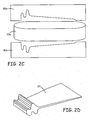
- FIGS. 2A-2D are schematic illustrations depicting a suitable forging process for forming an airfoil assembly
- FIGS. 3A-3I are perspective views depicting an alterative forging process, which include multiple compressive strain applications
- FIG. 4A is a macrograph of an extruded part prior to forging
- FIG. 4B is a macrograph of the metal part shown in FIG. 4A after forging.
- FIG. 5 is a graph of yield strengths and ductilities versus applied compressive strains for exemplary metal parts of the present invention and comparative metal parts.
- FIG. 1 is a flow diagram of method 10, which is a method for processing a metal part to increase its ductility, while also substantially retaining its strength.
- Method 10 includes steps 12-18, and initially involves extruding a AI-RE-TM alloy to form an extruded part (step 12).
- the extrusion process includes vacuum hot pressing the alloy into a porous billet and extruding the billet through an extrusion die.
- the billet can be extruded with a variety of extrusion-based systems, such as those commercially available from SAPA, Inc., Portland, OR. Suitable extrusion temperatures range from about 300°C to about 500°C.
- the extrusion system compresses and plastically deforms the billet to form the extruded part with a dense (i.e., substantially non-porous) alloy.
- the extruded part exits the extrusion system with an extrusion axis that extends along the length of the extruded part.
- the extruded part has a high strength, but low ductility (e.g., elongations to failure ranging from 1-4%). Suitable yield strengths for the extruded part range from about 620 megaPascals (MPa) (about 90 Ksi) to about 830 MPa (about 120 Ksi).
- the extruded part is then subjected to secondary processing. This involves heating the extruded part to a temperature that is above the crystallization temperature of the Al-RE-TM alloy (step 14). This causes the Al-RE-TM alloy to form a plastic-like state, thereby allowing the alloy to be plastically deformable.
- suitable temperatures for heating the extruded part range from about 300°C to about 450°C, with particularly suitable temperatures ranging from about 350°C to about 400°C.
- a compressive strain greater than 50% is applied to the heated extruded part (step 16).
- the compressive strain is applied to the heated extruded part in a direction that is substantially parallel to the extrusion axis.
- the Al-RE-TM alloy may be upset in a direction that is substantially parallel to the extrusion axis to form a variety of parts, such as turbine disks and blades.
- the compressive strain is applied to the heated extruded part in a direction that is substantially perpendicular to the extrusion axis. Perpendicular applications are suitable for simple blade forging.
- suitable applied compressive strains include compressive strains greater than about 50%, with particularly suitable compressive strains ranging from about 70% to about 90%.
- the applied compressive strains may be obtained with strain rates ranging from about 0.0001 seconds -1 to about 1,000 seconds -1 . This corresponds to strain rates ranging from slow strain rates of isothermal forging (e.g., for producing disks) to high strain rates of mechanical or hammer forgings (e.g., for producing blades).
- the heating and applied compressive strains of steps 14 and 16 may be performed in a variety of secondary processes.
- suitable secondary processes for heating and applying the compressive strains to the extruded part include forging operations and hot rolling operations.
- suitable forging systems for use with method 10 include thermal forging systems (e.g., systems commercially available from Weber Metals, Inc., Paramount, CA), mechanical forging systems (e.g., systems commercially available from Turbine Engine Component Technologies (TECT) Corporation, Newington, CT), and hammer forging systems (e.g., systems commercially available from Precision Components International, Inc., Columbus, GA).
- Suitable commercially available hot rolling systems include systems from Oak Ridge National Laboratory, Oak Ridge, TN; and systems from Material Sciences Corporation (Oak Ridge, TN).
- steps 14 and 16 are repeated until a desired strength and ductility are obtained.
- the extruded part may be heated and upset forged to a compressive strain greater than 50%.
- the forged metal part is then re-extruded or drawn to a size that fills a desired die dimension, and then close-die forged.
- the metal part is desirably drawn using small bites on the outer diameter.
- the drawing and upset forging may be repeated multiple times (e.g., 2-5 times), where each drawing uses small bites on the outer diameter and each upset forging applies a compressive strain greater than 50%.
- the resulting metal part is deformed from the extruded part dimensions due to the applied compressive strain.
- the metal part substantially retains its pre-secondary process strengths.
- suitable yield strengths for the metal parts after the heating and applied compressive strains of steps 14 and 16 include at least about 90% of the yield strength of the extruded part, with particularly suitable yield strengths including at least about 95% the yield strength of the extruded part.
- the yield strengths are determined pursuant to ASTM E8-04, entitled "Test Methods of Tension Testing of Metallic Materials".
- the ductility of the resulting metal part substantially increases due to the secondary processing.
- the secondary processing desirably increases the ductility of the metal part to a value of at least about 5%, where the ductilities are determined as tensile elongations to failure, pursuant to ASTM E8-04.
- suitable ductility increases for the metal part include percent increases of at least about 5%, with particularly suitable increases of at least about 10%, where the percent increases are relative to the ductility of the extruded part.
- the retained yield strengths and substantially-increased ductility allow the metal parts to be used in a variety of structural applications that require high ductility, such as aviation and aerospace applications.
- the metal part is then incorporated into an assembled structure (step 18).
- the metal part may also undergo post-processing operations (e.g., cutting, polishing, and painting) before or after incorporation into the assembled structure.
- post-processing operations e.g., cutting, polishing, and painting
- the metal parts maybe incorporated into a variety of assembled structures. Examples of suitable assembled structures and assembly techniques involving friction stir welding are disclosed in US patent application No. 11/818,701 entitled “Friction Stir Welded Structures Derived from Al-RE-TM alloys"; and in US patent application No. 11/818,931 entitled “Hollow Structures Formed with Friction Stir Welding".
- FIGS. 2A-2D are schematic illustrations of a suitable forging process for forming an airfoil assembly, pursuant to steps 14 and 16 of method 10 (shown in FIG. 1).
- FIG. 2A is a top view of forging die 20, which retains extruded part 22 and potting block 24.
- Forging die 20 includes die wall 26 and cavity 28 defined by die wall 26.
- Extruded part 22 is a part extruded from an Al-RE-TM alloy pursuant to step 12 of method 10 (shown in FIG. 1 ).
- Extruded part 22 is encased in potting block 24, which is a block of potting material for protecting extruded part 22 during the forging process.
- extruded part 22 and potting block 24 are placed within cavity 28, and are heated pursuant to step 14 of method 10 (shown in FIG. 1 ).
- a compressive force is applied downward onto extruded part 22 and potting block 24 with a punch mechanism. This applies a compressive strain greater than 50% on extruded part 22 in a direction parallel to its extrusion axis, and causes extruded part 22 and potting block 24 to deform to the dimensions of die wall 26.
- FIG. 2B is a top view of forging die 20 after extruded part 22 and potting block 24 are compressed (referred to as metal part 22a and potting block 24a, respectively).
- metal part 22a and potting block 24a are deformed to dimensions of die wall 26. This arrangement increases the compressive strain applied to extruded part 22 in the direction of its extrusion axis. Additionally, the resulting elongated shape of metal part 22a is readily shaped into an airfoil assembly. After the forging process, metal part 22a is removed from potting block 24a, and is then ready for shaping into an airfoil assembly.
- FIG. 2C is a perspective view of metal part 22a disposed between die block halves 30a and 30b of a blocker forging system.
- Metal part 22a is heated and die block halves 30a and 30b compress metal part 26a to form an airfoil assembly (not shown in FIG. 2C ).
- Die block halves 30a and 30b also desirably apply a compressive strain greater than 50% on metal part 22a to substantially retain the pre-secondary process strengths of metal part 22a.
- the resulting forged airfoil assembly may also undergo bubble forging treatment.
- FIG. 2D is a perspective view of airfoil assembly 32 forged from metal part 22a by die block halves 30a and 30b (shown in FIG. 2C ). Due to the forging operation on extruded part 22 with forging system 20, airfoil assembly 32 retains the strengths of extruded part 22 and has an increased ductility relative to extruded part 22. As such, airfoil assembly 32 is suitable for use in aviation and aerospace applications.
- FIGS. 3A-3I are perspective views of metal part 34 encased in potting block 36, which illustrate an alternative embodiment to steps 14 and 16 of method 10 (shown in FIG. 1 ). In this embodiment, multiple compressive strains are successively applied to metal part 34 in different directions to increase the ductility of metal part 34.
- metal part 34 is an extruded part that is initially encased in potting block 36.
- Metal part 34 has extrusion axis 38a and lateral axes 38b and 38c, where lateral axes 38b and 38c are substantially orthogonal to extrusion axis 38a and to each other.
- Metal part 34 and potting block 36 are initially oriented in a forging system (not shown) such that extrusion axis 38a extends vertically.
- Metal part 34 and potting block 36 are then heated and subjected to a first compressive strain greater than 50% in a direction parallel to extrusion axis 38a (represented by arrow 40). This vertically compresses metal part 34 and potting block 36 along extrusion axis 38a, thereby increasing their respective diameters.
- FIG. 3B shows metal part 34 and potting block 36 after the compressive strain is applied. Metal part 34 and potting block 36 are then drawn in the directions of lateral axes 38b and 38c until potting block 36 forms a rectangular prism.
- FIG. 3C shows metal part 34 and potting block 36 after being laterally drawn. As shown, potting block 36 is a rectangular prism having a length along axis 38b about 2.5 times longer than its height and depth along axes 38a and 38c, respectively.
- metal part 34 and potting block 36 are then reoriented in the forging system such that axis 38b extends vertically.
- Metal part 34 and potting block 36 are then heated and subjected to a second compressive strain greater than 50% in a direction parallel to axis 38b (represented by arrow 42). Accordingly, the second compressive strain is applied in a direction that is substantially perpendicular to the first compressive strain, and to extrusion axis 38a. This vertically compresses metal part 34 and potting block 36 along axis 38b.
- FIG. 3E shows metal part 34 and potting block 36 after the second compressive strain is applied.
- Metal part 34 and potting block 36 are then reoriented such that extrusion axis 38a extends vertically, and are drawn laterally in the directions of axes 38b and 38c until potting block 36 forms a second rectangular prism.
- FIG. 3F shows metal part 34 and potting block 36 after being laterally drawn. As shown, potting block 36 is a rectangular prism having a length along axis 38c about 2.5 times longer than its height and depth along axes 38a and 38b, respectively.
- metal part 34 and potting block 36 are then reoriented in the forging system such that axis 38c extends vertically.
- Metal part 34 and potting block 36 are then heated and subjected to a third compressive strain greater than 50% in a direction parallel to axis 38c (represented by arrow 44). Accordingly, the third compressive strain is applied in a direction that is substantially perpendicular to the first and second compressive strains, and to extrusion axis 38a. This vertically compresses metal part 34 and potting block 36 along axis 38c.
- FIG. 3H shows metal part 34 and potting block 36 after the third compressive strain is applied. After the third compressive strain is applied, metal part 34 and potting block 36 are then reoriented such that extrusion axis 38a extends vertically, and are drawn laterally in the directions of axes 38b and 38c until potting block 36 forms a third rectangular prism.
- FIG. 3I shows metal part 34 and potting block 36 after being laterally drawn.
- potting block 36 has a length along axis 38c that is substantially longer than its height and depth along axes 38a and 38b, respectively.
- This provides an elongated shape for metal part 34, which is similar to the shape of metal part 24a (shown in FIG. 2B ). As such, metal part 34 is readily shaped into an airfoil assembly, as discussed above.
- the Al-RE-TM alloys used to form extruded parts during the extrusion process in step 12 of method 10 are glassy, partially-devitrified, or fully devitrified alloys that at least include aluminum (Al), a rare earth metal (RE), and a transition metal (TM).
- Suitable concentrations of the aluminum in the alloy include the balance between the entire alloy weight and the sum of the concentrations of the other metals in the alloy (e.g., the sum of the concentrations of the rare earth metal and the transition metal).
- Suitable concentrations of the rare earth metal in the alloy range from about 3% by weight to about 20% by weight, with particularly suitable concentrations ranging from about 7% by weight to about 13% by weight, based on the entire weight of the alloy.
- Suitable concentrations of the transition metal in the alloy range from about 0.1% by weight to about 20% by weight, with particularly suitable concentrations ranging from about 1% by weight to about 15% by weight, based on the entire weight of the alloy. Additional examples of suitable Al-RE-TM alloys include those disclosed in U.S. Patent No. 6,974,510 .
- the Al-RE-TM alloy also includes one or more additional metals, such as magnesium, scandium, titanium, zirconium, iron, cobalt, gadolinium, and combinations thereof. Suitable concentrations of the additional metals in the alloy range from about 0.1 % by weight to about 10% by weight, with particularly suitable concentrations ranging from about 1% by weight to about 5% by weight, based on the entire weight of the alloy.
- additional metals such as magnesium, scandium, titanium, zirconium, iron, cobalt, gadolinium, and combinations thereof.
- Al-RE-TM alloy for use in forming extruded parts includes an alloy of aluminum-yttrium (Y)-nickel (Ni)-cobalt (Co) (referred to herein as an "Al-Y-Ni-Co" alloy), where yttrium is referred to as a rare earth element.
- Extruded rods of Examples 1 and 2 and Comparative Examples A and B were initially formed by extruding an Al-Y-Ni-Co alloy with an extrusion system commercially available from SAPA, Inc., Portland, OR.
- FIG. 4A is a macrograph of the extruded rod of Example 2, and is illustrative of the extruded rods of Examples 1 and 2 and Comparative Examples A and B.
- the extruded rod of Example 2 had a length of 34.0 millimeters (mm) (1.34 inches) and a diameter of 17.3 mm (0.68 inches).
- the extruded rods of Examples 1 and 2 and Comparative Example B were then forged with a forging system.
- the extruded rod of Comparative Example A was not subjected to the forging process.
- the forging system used was commercially available from Weber Metals, Inc., Paramount, CA.
- the forging involved heating the extruded rods to a temperature of 350°C (662°F) and applying a compressive strain to the heated extruded rod in a direction parallel to the extrusion axis. This compressed the lengths of the extruded rods of Examples 1 and 2 and Comparative Example B, thereby shortening the lengths and increasing the diameters.
- the compressive strain was continuously increased with a strain rate of 0.0002 seconds -1 , and until a predetermined compressive strain was reached.
- the predetermined compressive strain for the heated extruded rods of Comparative Example B and Examples 1 and 2 were 50%, 70%, and 85%, respectively.
- FIG. 4B is a macrograph of the resulting metal rod of Example 2 after the forging process.
- the Al-Y-Ni-Co alloy was forgeable, and the metal rod of Example 2 exhibited only a limited amount of edge cracking.
- the forged metal rod of Example 2 had a length of 4.60 mm (0.18 inches) and a diameter of 48.0 mm (1.89 inches).
- the room temperature yield strengths and ductilities of the resulting metal rods of Examples 1 and 2 and Comparative Examples A and B were then measured.
- the yield strengths and the ductilities i.e., tensile elongations to failure) were each determined pursuant to ASTM E8-04.
- FIG. 5 is a graph of the yield strengths and ductilities (i.e., elongations to failure) of the metal rods of Examples 1 and 2 and Comparative Examples A and B.
- the yields strengths were substantially unchanged by the applied compressive strains. However, when the applied compressive strains exceed about 50%, the ductilities substantially increased. Between compressive strains of 50% and 70%, the ductilities of the metal rods increased by about 8%, and between compressive strains of 50% and 85%, the ductilities of the metal rods increased by more than 10%.
- the application of a compressive strain greater than about 50% in a direction that is substantially parallel to the extrusion axis substantially increases the ductility of the Al-RE-TM alloys, thereby allowing such alloys to be used in a variety of applications (e.g., aviation and aerospace applications).
- Extruded rods of Example 3 and Comparative Example C were formed from an Al-Y-Ni-Co alloy in the same manner as discussed above for Examples 1 and 2 and Comparative Examples A and B. After the extrusion process, the extruded rod of Example 3 was then hot rolled with a hot rolling system commercially available from Material Sciences Corporation, Oak Ridge, TN. The hot rolling system heated the metal rod to a temperature of 350°C (662°F) and applied a compressive strain of 70% to the extruded rod in a direction perpendicular to the extrusion axis. The extruded rod of Comparative Example C was not hot rolled.
- the data in Table 1 shows that the hot rolling process also allows the metal rod of Example 3 to substantially retain its pre-secondary processing yield strength (i.e., about 91% retention). Additionally, the ductility of the metal rod of Example 3 is substantially increased compared to the ductility of the extruded rod of Comparative Example C. While the forging process discussed above for Examples 1 and 2 provided greater strength retentions and ductility increases, the hot rolling process also increased the ductility of the metal rod to above 5%. As such, the hot rolling process is also suitable for providing metal parts derived from Al-RE-TM alloys that can be used in aviation and aerospace applications.
Landscapes
- Chemical & Material Sciences (AREA)
- Engineering & Computer Science (AREA)
- Materials Engineering (AREA)
- Mechanical Engineering (AREA)
- Metallurgy (AREA)
- Organic Chemistry (AREA)
- Physics & Mathematics (AREA)
- Thermal Sciences (AREA)
- Crystallography & Structural Chemistry (AREA)
- Forging (AREA)
Abstract
Description
- The present invention relates to metal structures derived from aluminum - rare earth - transition metal (Al-RE-TM) alloys. In particular, the present invention relates to processing techniques for improving the ductility of metal parts derived from Al-RE-TM alloys.
- Al-RE-TM alloys have been considered for structural applications in the aerospace industry. Such alloys have high strengths, and can be formed into a variety of different structures. Furthermore, due to the lower density of aluminum, as compared to well-established alloys such as titanium, Al-RE-TM alloys are also capable of providing significant weight savings.
- To obtain good glass-formability, aluminum-based alloys typically include high atomic percentages of rare earth and transition metal elements. However, such alloys accordingly have high volume fractions of intermetallic phases in the devitrified state, which results in alloys having low ductility (e.g., elongations less than 5%). High ductility is desirable for many aerospace applications. As such, there is a need for processing techniques that improve the ductility of Al-RE-TM alloys, while also preserving the strengths of the alloys.
- The present invention relates to a method for processing a metal part. The method includes extruding a Al-RE-TM alloy to form an extruded part having an extrusion axis. The extruded part is then heated and subjected to a compressive strain greater than 50%.
- Certain preferred embodiments of the present invention will now be described, by way of example only, with reference to the accompanying drawings, in which:
-
FIG. 1 is a flow diagram of a method of processing a metal part derived from a Al-RE-TM alloy to improve the ductility of the metal part; -
FIGS. 2A-2D are schematic illustrations depicting a suitable forging process for forming an airfoil assembly; -
FIGS. 3A-3I are perspective views depicting an alterative forging process, which include multiple compressive strain applications; -
FIG. 4A is a macrograph of an extruded part prior to forging; -
FIG. 4B is a macrograph of the metal part shown inFIG. 4A after forging; and -
FIG. 5 is a graph of yield strengths and ductilities versus applied compressive strains for exemplary metal parts of the present invention and comparative metal parts. -
FIG. 1 is a flow diagram ofmethod 10, which is a method for processing a metal part to increase its ductility, while also substantially retaining its strength.Method 10 includes steps 12-18, and initially involves extruding a AI-RE-TM alloy to form an extruded part (step 12). The extrusion process includes vacuum hot pressing the alloy into a porous billet and extruding the billet through an extrusion die. The billet can be extruded with a variety of extrusion-based systems, such as those commercially available from SAPA, Inc., Portland, OR. Suitable extrusion temperatures range from about 300°C to about 500°C. - The extrusion system compresses and plastically deforms the billet to form the extruded part with a dense (i.e., substantially non-porous) alloy. The extruded part exits the extrusion system with an extrusion axis that extends along the length of the extruded part. The extruded part has a high strength, but low ductility (e.g., elongations to failure ranging from 1-4%). Suitable yield strengths for the extruded part range from about 620 megaPascals (MPa) (about 90 Ksi) to about 830 MPa (about 120 Ksi).
- To increase the ductility of the extruded part, the extruded part is then subjected to secondary processing. This involves heating the extruded part to a temperature that is above the crystallization temperature of the Al-RE-TM alloy (step 14). This causes the Al-RE-TM alloy to form a plastic-like state, thereby allowing the alloy to be plastically deformable. Examples of suitable temperatures for heating the extruded part range from about 300°C to about 450°C, with particularly suitable temperatures ranging from about 350°C to about 400°C.
- While the extruded part remains heated at the above-discussed temperatures, a compressive strain greater than 50% (i.e., an upset greater than 50%) is applied to the heated extruded part (step 16). In one embodiment, the compressive strain is applied to the heated extruded part in a direction that is substantially parallel to the extrusion axis. For example, the Al-RE-TM alloy may be upset in a direction that is substantially parallel to the extrusion axis to form a variety of parts, such as turbine disks and blades. In an alternative embodiment, the compressive strain is applied to the heated extruded part in a direction that is substantially perpendicular to the extrusion axis. Perpendicular applications are suitable for simple blade forging.
- Examples of suitable applied compressive strains include compressive strains greater than about 50%, with particularly suitable compressive strains ranging from about 70% to about 90%. The applied compressive strains may be obtained with strain rates ranging from about 0.0001 seconds-1 to about 1,000 seconds-1. This corresponds to strain rates ranging from slow strain rates of isothermal forging (e.g., for producing disks) to high strain rates of mechanical or hammer forgings (e.g., for producing blades).
- The heating and applied compressive strains of
steps method 10 include thermal forging systems (e.g., systems commercially available from Weber Metals, Inc., Paramount, CA), mechanical forging systems (e.g., systems commercially available from Turbine Engine Component Technologies (TECT) Corporation, Newington, CT), and hammer forging systems (e.g., systems commercially available from Precision Components International, Inc., Columbus, GA). Suitable commercially available hot rolling systems include systems from Oak Ridge National Laboratory, Oak Ridge, TN; and systems from Material Sciences Corporation (Oak Ridge, TN). - In an alternative embodiment,
steps - After
steps steps - In addition, the ductility of the resulting metal part substantially increases due to the secondary processing. The secondary processing desirably increases the ductility of the metal part to a value of at least about 5%, where the ductilities are determined as tensile elongations to failure, pursuant to ASTM E8-04. Examples of suitable ductility increases for the metal part include percent increases of at least about 5%, with particularly suitable increases of at least about 10%, where the percent increases are relative to the ductility of the extruded part. The retained yield strengths and substantially-increased ductility allow the metal parts to be used in a variety of structural applications that require high ductility, such as aviation and aerospace applications.
- After the secondary processing of
steps method 10, the metal parts maybe incorporated into a variety of assembled structures. Examples of suitable assembled structures and assembly techniques involving friction stir welding are disclosed inUS patent application No. 11/818,701 US patent application No. 11/818,931 -
FIGS. 2A-2D are schematic illustrations of a suitable forging process for forming an airfoil assembly, pursuant tosteps FIG. 1). FIG. 2A is a top view of forgingdie 20, which retains extrudedpart 22 andpotting block 24. Forgingdie 20 includesdie wall 26 andcavity 28 defined bydie wall 26. Extrudedpart 22 is a part extruded from an Al-RE-TM alloy pursuant to step 12 of method 10 (shown inFIG. 1 ). Extrudedpart 22 is encased inpotting block 24, which is a block of potting material for protecting extrudedpart 22 during the forging process. - During the forging process, extruded
part 22 andpotting block 24 are placed withincavity 28, and are heated pursuant to step 14 of method 10 (shown inFIG. 1 ). A compressive force is applied downward onto extrudedpart 22 andpotting block 24 with a punch mechanism. This applies a compressive strain greater than 50% onextruded part 22 in a direction parallel to its extrusion axis, and causes extrudedpart 22 andpotting block 24 to deform to the dimensions ofdie wall 26. -
FIG. 2B is a top view of forgingdie 20 after extrudedpart 22 andpotting block 24 are compressed (referred to asmetal part 22a andpotting block 24a, respectively). As shown,metal part 22a andpotting block 24a are deformed to dimensions ofdie wall 26. This arrangement increases the compressive strain applied to extrudedpart 22 in the direction of its extrusion axis. Additionally, the resulting elongated shape ofmetal part 22a is readily shaped into an airfoil assembly. After the forging process,metal part 22a is removed from pottingblock 24a, and is then ready for shaping into an airfoil assembly. -
FIG. 2C is a perspective view ofmetal part 22a disposed betweendie block halves Metal part 22a is heated and dieblock halves FIG. 2C ). Dieblock halves metal part 22a to substantially retain the pre-secondary process strengths ofmetal part 22a. The resulting forged airfoil assembly may also undergo bubble forging treatment. -
FIG. 2D is a perspective view ofairfoil assembly 32 forged frommetal part 22a bydie block halves FIG. 2C ). Due to the forging operation onextruded part 22 with forgingsystem 20,airfoil assembly 32 retains the strengths ofextruded part 22 and has an increased ductility relative to extrudedpart 22. As such,airfoil assembly 32 is suitable for use in aviation and aerospace applications. -
FIGS. 3A-3I are perspective views ofmetal part 34 encased inpotting block 36, which illustrate an alternative embodiment tosteps FIG. 1 ). In this embodiment, multiple compressive strains are successively applied tometal part 34 in different directions to increase the ductility ofmetal part 34. - As shown in
FIG. 3A ,metal part 34 is an extruded part that is initially encased inpotting block 36.Metal part 34 hasextrusion axis 38a andlateral axes lateral axes extrusion axis 38a and to each other.Metal part 34 andpotting block 36 are initially oriented in a forging system (not shown) such thatextrusion axis 38a extends vertically.Metal part 34 andpotting block 36 are then heated and subjected to a first compressive strain greater than 50% in a direction parallel toextrusion axis 38a (represented by arrow 40). This vertically compressesmetal part 34 andpotting block 36 alongextrusion axis 38a, thereby increasing their respective diameters. - .
FIG. 3B showsmetal part 34 andpotting block 36 after the compressive strain is applied.Metal part 34 andpotting block 36 are then drawn in the directions oflateral axes block 36 forms a rectangular prism.FIG. 3C showsmetal part 34 andpotting block 36 after being laterally drawn. As shown, pottingblock 36 is a rectangular prism having a length alongaxis 38b about 2.5 times longer than its height and depth alongaxes - As shown in
FIG. 3D ,metal part 34 andpotting block 36 are then reoriented in the forging system such thataxis 38b extends vertically.Metal part 34 andpotting block 36 are then heated and subjected to a second compressive strain greater than 50% in a direction parallel toaxis 38b (represented by arrow 42). Accordingly, the second compressive strain is applied in a direction that is substantially perpendicular to the first compressive strain, and toextrusion axis 38a. This vertically compressesmetal part 34 andpotting block 36 alongaxis 38b. -
FIG. 3E showsmetal part 34 andpotting block 36 after the second compressive strain is applied.Metal part 34 andpotting block 36 are then reoriented such thatextrusion axis 38a extends vertically, and are drawn laterally in the directions ofaxes block 36 forms a second rectangular prism.FIG. 3F showsmetal part 34 andpotting block 36 after being laterally drawn. As shown, pottingblock 36 is a rectangular prism having a length alongaxis 38c about 2.5 times longer than its height and depth alongaxes - As shown in
FIG. 3G ,metal part 34 andpotting block 36 are then reoriented in the forging system such thataxis 38c extends vertically.Metal part 34 andpotting block 36 are then heated and subjected to a third compressive strain greater than 50% in a direction parallel toaxis 38c (represented by arrow 44). Accordingly, the third compressive strain is applied in a direction that is substantially perpendicular to the first and second compressive strains, and toextrusion axis 38a. This vertically compressesmetal part 34 andpotting block 36 alongaxis 38c. -
FIG. 3H showsmetal part 34 andpotting block 36 after the third compressive strain is applied. After the third compressive strain is applied,metal part 34 andpotting block 36 are then reoriented such thatextrusion axis 38a extends vertically, and are drawn laterally in the directions ofaxes block 36 forms a third rectangular prism. -
FIG. 3I showsmetal part 34 andpotting block 36 after being laterally drawn. As shown, pottingblock 36 has a length alongaxis 38c that is substantially longer than its height and depth alongaxes metal part 34, which is similar to the shape ofmetal part 24a (shown inFIG. 2B ). As such,metal part 34 is readily shaped into an airfoil assembly, as discussed above. - The Al-RE-TM alloys used to form extruded parts during the extrusion process in
step 12 of method 10 (shown inFIG. 1 ) are glassy, partially-devitrified, or fully devitrified alloys that at least include aluminum (Al), a rare earth metal (RE), and a transition metal (TM). Suitable concentrations of the aluminum in the alloy include the balance between the entire alloy weight and the sum of the concentrations of the other metals in the alloy (e.g., the sum of the concentrations of the rare earth metal and the transition metal). Suitable concentrations of the rare earth metal in the alloy range from about 3% by weight to about 20% by weight, with particularly suitable concentrations ranging from about 7% by weight to about 13% by weight, based on the entire weight of the alloy. Suitable concentrations of the transition metal in the alloy range from about 0.1% by weight to about 20% by weight, with particularly suitable concentrations ranging from about 1% by weight to about 15% by weight, based on the entire weight of the alloy. Additional examples of suitable Al-RE-TM alloys include those disclosed inU.S. Patent No. 6,974,510 . - In one embodiment, the Al-RE-TM alloy also includes one or more additional metals, such as magnesium, scandium, titanium, zirconium, iron, cobalt, gadolinium, and combinations thereof. Suitable concentrations of the additional metals in the alloy range from about 0.1 % by weight to about 10% by weight, with particularly suitable concentrations ranging from about 1% by weight to about 5% by weight, based on the entire weight of the alloy. An example of a particularly suitable Al-RE-TM alloy for use in forming extruded parts includes an alloy of aluminum-yttrium (Y)-nickel (Ni)-cobalt (Co) (referred to herein as an "Al-Y-Ni-Co" alloy), where yttrium is referred to as a rare earth element.
- The present invention is more particularly described in the following examples that are intended as illustrations only, since numerous modifications and variations within the scope of the present invention will be apparent to those skilled in the art. Unless otherwise noted, all parts, percentages, and ratios reported in the following examples are on a weight basis.
- , Extruded rods of Examples 1 and 2 and Comparative Examples A and B were initially formed by extruding an Al-Y-Ni-Co alloy with an extrusion system commercially available from SAPA, Inc., Portland, OR.
FIG. 4A is a macrograph of the extruded rod of Example 2, and is illustrative of the extruded rods of Examples 1 and 2 and Comparative Examples A and B. The extruded rod of Example 2 had a length of 34.0 millimeters (mm) (1.34 inches) and a diameter of 17.3 mm (0.68 inches). - The extruded rods of Examples 1 and 2 and Comparative Example B were then forged with a forging system. The extruded rod of Comparative Example A was not subjected to the forging process. The forging system used was commercially available from Weber Metals, Inc., Paramount, CA. The forging involved heating the extruded rods to a temperature of 350°C (662°F) and applying a compressive strain to the heated extruded rod in a direction parallel to the extrusion axis. This compressed the lengths of the extruded rods of Examples 1 and 2 and Comparative Example B, thereby shortening the lengths and increasing the diameters. The compressive strain was continuously increased with a strain rate of 0.0002 seconds-1, and until a predetermined compressive strain was reached. The predetermined compressive strain for the heated extruded rods of Comparative Example B and Examples 1 and 2 were 50%, 70%, and 85%, respectively.
-
FIG. 4B is a macrograph of the resulting metal rod of Example 2 after the forging process. As shown, the Al-Y-Ni-Co alloy was forgeable, and the metal rod of Example 2 exhibited only a limited amount of edge cracking. The forged metal rod of Example 2 had a length of 4.60 mm (0.18 inches) and a diameter of 48.0 mm (1.89 inches). The room temperature yield strengths and ductilities of the resulting metal rods of Examples 1 and 2 and Comparative Examples A and B were then measured. The yield strengths and the ductilities (i.e., tensile elongations to failure) were each determined pursuant to ASTM E8-04. -
FIG. 5 is a graph of the yield strengths and ductilities (i.e., elongations to failure) of the metal rods of Examples 1 and 2 and Comparative Examples A and B. As shown inFIG. 5 , the yields strengths were substantially unchanged by the applied compressive strains. However, when the applied compressive strains exceed about 50%, the ductilities substantially increased. Between compressive strains of 50% and 70%, the ductilities of the metal rods increased by about 8%, and between compressive strains of 50% and 85%, the ductilities of the metal rods increased by more than 10%. Accordingly, the application of a compressive strain greater than about 50% in a direction that is substantially parallel to the extrusion axis substantially increases the ductility of the Al-RE-TM alloys, thereby allowing such alloys to be used in a variety of applications (e.g., aviation and aerospace applications). - Extruded rods of Example 3 and Comparative Example C were formed from an Al-Y-Ni-Co alloy in the same manner as discussed above for Examples 1 and 2 and Comparative Examples A and B. After the extrusion process, the extruded rod of Example 3 was then hot rolled with a hot rolling system commercially available from Material Sciences Corporation, Oak Ridge, TN. The hot rolling system heated the metal rod to a temperature of 350°C (662°F) and applied a compressive strain of 70% to the extruded rod in a direction perpendicular to the extrusion axis. The extruded rod of Comparative Example C was not hot rolled.
- The room temperature yield strengths, tensile strengths, and ductilities of the rods of Example 3 and Comparative Example C were then measured. The yield strengths and the ductilities (i.e., tensile elongations to failure) were each determined pursuant to ASTM E8-04. Table 1 provides the measured yield strengths, tensile strengths, and ductilities for the rods of Example 3 and Comparative Example C.
TABLE 1 Example Yield Strength Tensile Strength Ductility (MPa) (MPa) Comparative Example C 636 654 1.7% Example 3 580 610 6.6% - The data in Table 1 shows that the hot rolling process also allows the metal rod of Example 3 to substantially retain its pre-secondary processing yield strength (i.e., about 91% retention). Additionally, the ductility of the metal rod of Example 3 is substantially increased compared to the ductility of the extruded rod of Comparative Example C. While the forging process discussed above for Examples 1 and 2 provided greater strength retentions and ductility increases, the hot rolling process also increased the ductility of the metal rod to above 5%. As such, the hot rolling process is also suitable for providing metal parts derived from Al-RE-TM alloys that can be used in aviation and aerospace applications.
- Although the present invention has been described with reference to preferred embodiments, workers skilled in the art will recognize that changes may be made in form and detail without departing from the scope of the invention.
Claims (11)
- A method for processing a metal part, the method comprising:extruding a Al-RE-TM alloy to form an extruded part having an extrusion axis;heating the extruded part to a temperature above a crystallization temperature of the Al-RE-TM alloy; andapplying a compressive strain greater than 50% on the heated part.
- The method of claim 1, wherein the compressive strain is applied in a direction that is substantially parallel to the extrusion axis.
- The method of claim 1 or 2, wherein the temperature that the extruded part is heated to ranges from 300°C to 450°C.
- The method of claim 3, wherein the temperature that the extruded part is heated to is in a range from 350°C to 400°C.
- The method of any preceding claim, wherein the compressive strain is applied with a strain rate ranging from 0.0001 seconds-1 to 1,000 seconds-1.
- The method of any preceding claim, wherein the applied compressive strain ranges from 70% to 90%.
- The method of any preceding claim, wherein the metal part has a tensile strength that is at least 90% of a tensile strength of the extruded part, wherein the tensile strength is measured pursuant to ASTM E8-04.
- The method of any preceding claim, wherein the Al-RE-TM alloy comprises an Al-Y-Ni-Co alloy.
- The method of any preceding claim, further comprising:creating a finished metal part after the heating and applying steps.
- The method of any preceding claim, whereinapplying a compressive strain on the heated metal part provides a ductility increase of at least 5% relative to a ductility of the extruded part, wherein the ductility is measured pursuant to ASTM E8-04.
- The method of any preceding claim, wherein the heating and applying steps comprises:forging the extruded part at a temperature above a crystallization temperature of the AI-RE-TM alloy, and with a compressive strain greater than 50% in a direction that is substantially parallel to the extrusion axis.
Applications Claiming Priority (1)
| Application Number | Priority Date | Filing Date | Title |
|---|---|---|---|
| US11/818,764 US20080308197A1 (en) | 2007-06-15 | 2007-06-15 | Secondary processing of structures derived from AL-RE-TM alloys |
Publications (2)
| Publication Number | Publication Date |
|---|---|
| EP2003224A1 true EP2003224A1 (en) | 2008-12-17 |
| EP2003224B1 EP2003224B1 (en) | 2015-11-11 |
Family
ID=39699017
Family Applications (1)
| Application Number | Title | Priority Date | Filing Date |
|---|---|---|---|
| EP08251428.2A Ceased EP2003224B1 (en) | 2007-06-15 | 2008-04-14 | Secondary processing of structures derived from AI-RE-TM Alloys |
Country Status (2)
| Country | Link |
|---|---|
| US (1) | US20080308197A1 (en) |
| EP (1) | EP2003224B1 (en) |
Families Citing this family (4)
| Publication number | Priority date | Publication date | Assignee | Title |
|---|---|---|---|---|
| US8409497B2 (en) * | 2009-10-16 | 2013-04-02 | United Technologies Corporation | Hot and cold rolling high strength L12 aluminum alloys |
| US8603267B2 (en) * | 2011-06-27 | 2013-12-10 | United Technologies Corporation | Extrusion of glassy aluminum-based alloys |
| US20120328472A1 (en) * | 2011-06-27 | 2012-12-27 | United Technologies Corporation | Forging of glassy aluminum-based alloys |
| WO2015006466A1 (en) | 2013-07-10 | 2015-01-15 | United Technologies Corporation | Aluminum alloys and manufacture methods |
Citations (2)
| Publication number | Priority date | Publication date | Assignee | Title |
|---|---|---|---|---|
| US20030156968A1 (en) | 2001-03-23 | 2003-08-21 | Hisao Hattori | Heat-resistant and creep-resistant aluminum alloy and billet thereof, and method for their production |
| US20040170522A1 (en) | 2003-02-28 | 2004-09-02 | Watson Thomas J. | Aluminum base alloys |
Family Cites Families (21)
| Publication number | Priority date | Publication date | Assignee | Title |
|---|---|---|---|---|
| US4466266A (en) * | 1981-10-08 | 1984-08-21 | Gkn Forgings Limited | Forging apparatus |
| US4781772A (en) * | 1988-02-22 | 1988-11-01 | Inco Alloys International, Inc. | ODS alloy having intermediate high temperature strength |
| JP2724762B2 (en) * | 1989-12-29 | 1998-03-09 | 本田技研工業株式会社 | High-strength aluminum-based amorphous alloy |
| US5111570A (en) * | 1990-08-10 | 1992-05-12 | United Technologies Corporation | Forge joining repair technique |
| JPH0565584A (en) * | 1991-09-05 | 1993-03-19 | Yoshida Kogyo Kk <Ykk> | Production of high strength aluminum alloy powder |
| US5386628A (en) * | 1991-12-23 | 1995-02-07 | United Technologies Corporation | Method of making a diffusion bonded rocket chamber |
| US5375325A (en) * | 1992-05-26 | 1994-12-27 | United Technologies Corporation | Method of making a rocket chamber construction |
| US5294169A (en) * | 1993-07-30 | 1994-03-15 | United Technologies Automotive, Inc. | Cover plate |
| CN1322242C (en) * | 1996-03-19 | 2007-06-20 | 株式会社日立制作所 | Structure for friction welding |
| US5733102A (en) * | 1996-12-17 | 1998-03-31 | General Electric Company | Slot cooled blade tip |
| AU747689B2 (en) * | 1998-10-30 | 2002-05-16 | Corus Aluminium Walzprodukte Gmbh | Composite aluminium panel |
| GB2383968B (en) * | 2002-01-15 | 2005-07-27 | Rolls Royce Plc | Friction welding |
| US7360676B2 (en) * | 2002-09-21 | 2008-04-22 | Universal Alloy Corporation | Welded aluminum alloy structure |
| JP3762370B2 (en) * | 2003-01-14 | 2006-04-05 | 本田技研工業株式会社 | Friction stir welding method and apparatus |
| US7093745B2 (en) * | 2003-01-14 | 2006-08-22 | Honda Motor Co., Ltd. | Method of and apparatus for friction stir welding |
| FR2855439B1 (en) * | 2003-05-27 | 2006-07-14 | Snecma Moteurs | METHOD FOR MANUFACTURING A HOLLOW DAWN FOR TURBOMACHINE |
| US7032800B2 (en) * | 2003-05-30 | 2006-04-25 | General Electric Company | Apparatus and method for friction stir welding of high strength materials, and articles made therefrom |
| US7048175B2 (en) * | 2003-12-19 | 2006-05-23 | The Boeing Company | Friction welded structural assembly and preform and method for same |
| US7300708B2 (en) * | 2004-03-16 | 2007-11-27 | General Electric Company | Erosion and wear resistant protective structures for turbine engine components |
| US7189064B2 (en) * | 2004-05-14 | 2007-03-13 | General Electric Company | Friction stir welded hollow airfoils and method therefor |
| US7210611B2 (en) * | 2004-10-21 | 2007-05-01 | The Boeing Company | Formed structural assembly and associated preform and method |
-
2007
- 2007-06-15 US US11/818,764 patent/US20080308197A1/en not_active Abandoned
-
2008
- 2008-04-14 EP EP08251428.2A patent/EP2003224B1/en not_active Ceased
Patent Citations (2)
| Publication number | Priority date | Publication date | Assignee | Title |
|---|---|---|---|---|
| US20030156968A1 (en) | 2001-03-23 | 2003-08-21 | Hisao Hattori | Heat-resistant and creep-resistant aluminum alloy and billet thereof, and method for their production |
| US20040170522A1 (en) | 2003-02-28 | 2004-09-02 | Watson Thomas J. | Aluminum base alloys |
Also Published As
| Publication number | Publication date |
|---|---|
| EP2003224B1 (en) | 2015-11-11 |
| US20080308197A1 (en) | 2008-12-18 |
Similar Documents
| Publication | Publication Date | Title |
|---|---|---|
| DE60313065T2 (en) | Thin products of beta or quasi-beta titanium alloys, forging production | |
| Valiev et al. | Producing bulk ultrafine-grained materials by severe plastic deformation | |
| US4110131A (en) | Method for powder-metallurgic production of a workpiece from a high temperature alloy | |
| DE69935891T2 (en) | Method for producing an engine lift valve | |
| EP2386663B1 (en) | Method for producing a component and component from a gamma-titanium-aluminium base alloy | |
| US20170081751A1 (en) | Method for producing a preform from an alpha+gamma titanium aluminide alloy for producing a component with high load-bearing capacity for piston engines and gas turbines, in particular aircraft engines | |
| KR101237122B1 (en) | Titanium alloy microstructural refinement method and high temperature-high strain superplastic forming of titanium alloys | |
| JP2020032466A (en) | Method of manufacturing forged products and other processed products | |
| EP2272993B1 (en) | Method for producing a forged article from a gamma-titanium-aluminium base alloy | |
| EP3257963A1 (en) | METHOD FOR MANUFACTURING Ni-BASED SUPER-HEAT-RESISTANT ALLOY | |
| EP3372700B1 (en) | Method for making forged tial components | |
| KR20150130961A (en) | Split-pass open-die forging for hard-to-forge, strain-path sensitive titanium-base and nickel-base alloys | |
| KR20160033096A (en) | Method for Manufacturing a Titanium-Aluminum Alloy Part | |
| JP6696202B2 (en) | α + β type titanium alloy member and manufacturing method thereof | |
| EP2003224B1 (en) | Secondary processing of structures derived from AI-RE-TM Alloys | |
| DE102009039344B4 (en) | Composite material and method of manufacture | |
| US5154780A (en) | Metallurgical products improved by deformation processing and method thereof | |
| JP3310155B2 (en) | Manufacturing method of seamless pipe of α + β type titanium alloy with excellent fracture toughness | |
| US6962673B2 (en) | Heat-resistant, creep-resistant aluminum alloy and billet thereof as well as methods of preparing the same | |
| JP2000271693A (en) | Manufacturing method of magnesium alloy material | |
| US20080145691A1 (en) | Articles having a continuous grain size radial gradient and methods for making the same | |
| Derakhshandeh et al. | Microstructure and mechanical properties of ultrafine-grained titanium processed by multi-pass ECAP at room temperature using core–sheath method | |
| EP2540856A1 (en) | Forging of glassy aluminum-based alloys | |
| Zhang et al. | Deformation properties and bending/diffusion bonding processing of a P/M Ti-22Al-25Nb alloy at elevated temperature | |
| JPH06306508A (en) | Production of low anisotropy and high fatigue strength titanium base composite material |
Legal Events
| Date | Code | Title | Description |
|---|---|---|---|
| PUAI | Public reference made under article 153(3) epc to a published international application that has entered the european phase |
Free format text: ORIGINAL CODE: 0009012 |
|
| AK | Designated contracting states |
Kind code of ref document: A1 Designated state(s): AT BE BG CH CY CZ DE DK EE ES FI FR GB GR HR HU IE IS IT LI LT LU LV MC MT NL NO PL PT RO SE SI SK TR |
|
| AX | Request for extension of the european patent |
Extension state: AL BA MK RS |
|
| 17P | Request for examination filed |
Effective date: 20090320 |
|
| 17Q | First examination report despatched |
Effective date: 20090417 |
|
| AKX | Designation fees paid |
Designated state(s): DE GB |
|
| GRAP | Despatch of communication of intention to grant a patent |
Free format text: ORIGINAL CODE: EPIDOSNIGR1 |
|
| INTG | Intention to grant announced |
Effective date: 20150518 |
|
| GRAS | Grant fee paid |
Free format text: ORIGINAL CODE: EPIDOSNIGR3 |
|
| GRAA | (expected) grant |
Free format text: ORIGINAL CODE: 0009210 |
|
| AK | Designated contracting states |
Kind code of ref document: B1 Designated state(s): DE GB |
|
| REG | Reference to a national code |
Ref country code: GB Ref legal event code: FG4D |
|
| REG | Reference to a national code |
Ref country code: DE Ref legal event code: R082 Ref document number: 602008041093 Country of ref document: DE Representative=s name: SCHMITT-NILSON SCHRAUD WAIBEL WOHLFROM PATENTA, DE Ref country code: DE Ref legal event code: R082 Ref document number: 602008041093 Country of ref document: DE Representative=s name: KSNH PATENTANWAELTE KLUNKER/SCHMITT-NILSON/HIR, DE |
|
| REG | Reference to a national code |
Ref country code: DE Ref legal event code: R096 Ref document number: 602008041093 Country of ref document: DE |
|
| REG | Reference to a national code |
Ref country code: DE Ref legal event code: R097 Ref document number: 602008041093 Country of ref document: DE |
|
| PLBE | No opposition filed within time limit |
Free format text: ORIGINAL CODE: 0009261 |
|
| STAA | Information on the status of an ep patent application or granted ep patent |
Free format text: STATUS: NO OPPOSITION FILED WITHIN TIME LIMIT |
|
| 26N | No opposition filed |
Effective date: 20160812 |
|
| REG | Reference to a national code |
Ref country code: DE Ref legal event code: R082 Ref document number: 602008041093 Country of ref document: DE Representative=s name: SCHMITT-NILSON SCHRAUD WAIBEL WOHLFROM PATENTA, DE |
|
| REG | Reference to a national code |
Ref country code: DE Ref legal event code: R082 Ref document number: 602008041093 Country of ref document: DE Representative=s name: SCHMITT-NILSON SCHRAUD WAIBEL WOHLFROM PATENTA, DE Ref country code: DE Ref legal event code: R081 Ref document number: 602008041093 Country of ref document: DE Owner name: UNITED TECHNOLOGIES CORP. (N.D.GES.D. STAATES , US Free format text: FORMER OWNERS: THE CURATORS OF THE UNIVERSITY OF MISSOURI, ROLLA, MO., US; UNITED TECHNOLOGIES CORP., HARTFORD, CONN., US Ref country code: DE Ref legal event code: R081 Ref document number: 602008041093 Country of ref document: DE Owner name: THE CURATORS OF THE UNIVERSITY OF MISSOURI, RO, US Free format text: FORMER OWNERS: THE CURATORS OF THE UNIVERSITY OF MISSOURI, ROLLA, MO., US; UNITED TECHNOLOGIES CORP., HARTFORD, CONN., US |
|
| PGFP | Annual fee paid to national office [announced via postgrant information from national office to epo] |
Ref country code: GB Payment date: 20220323 Year of fee payment: 15 |
|
| PGFP | Annual fee paid to national office [announced via postgrant information from national office to epo] |
Ref country code: DE Payment date: 20220322 Year of fee payment: 15 |
|
| REG | Reference to a national code |
Ref country code: DE Ref legal event code: R081 Ref document number: 602008041093 Country of ref document: DE Owner name: THE CURATORS OF THE UNIVERSITY OF MISSOURI, RO, US Free format text: FORMER OWNERS: THE CURATORS OF THE UNIVERSITY OF MISSOURI, ROLLA, MO., US; UNITED TECHNOLOGIES CORP. (N.D.GES.D. STAATES DELAWARE), FARMINGTON, CONN., US Ref country code: DE Ref legal event code: R081 Ref document number: 602008041093 Country of ref document: DE Owner name: RAYTHEON TECHNOLOGIES CORPORATION (N.D.GES.D.S, US Free format text: FORMER OWNERS: THE CURATORS OF THE UNIVERSITY OF MISSOURI, ROLLA, MO., US; UNITED TECHNOLOGIES CORP. (N.D.GES.D. STAATES DELAWARE), FARMINGTON, CONN., US |
|
| REG | Reference to a national code |
Ref country code: DE Ref legal event code: R119 Ref document number: 602008041093 Country of ref document: DE |
|
| GBPC | Gb: european patent ceased through non-payment of renewal fee |
Effective date: 20230414 |
|
| PG25 | Lapsed in a contracting state [announced via postgrant information from national office to epo] |
Ref country code: GB Free format text: LAPSE BECAUSE OF NON-PAYMENT OF DUE FEES Effective date: 20230414 |
|
| PG25 | Lapsed in a contracting state [announced via postgrant information from national office to epo] |
Ref country code: GB Free format text: LAPSE BECAUSE OF NON-PAYMENT OF DUE FEES Effective date: 20230414 Ref country code: DE Free format text: LAPSE BECAUSE OF NON-PAYMENT OF DUE FEES Effective date: 20231103 |