EP2003221A1 - Very thin hard steel sheet and method for producing the same - Google Patents
Very thin hard steel sheet and method for producing the same Download PDFInfo
- Publication number
- EP2003221A1 EP2003221A1 EP07741011A EP07741011A EP2003221A1 EP 2003221 A1 EP2003221 A1 EP 2003221A1 EP 07741011 A EP07741011 A EP 07741011A EP 07741011 A EP07741011 A EP 07741011A EP 2003221 A1 EP2003221 A1 EP 2003221A1
- Authority
- EP
- European Patent Office
- Prior art keywords
- steel sheet
- phase
- average
- major axis
- thin steel
- Prior art date
- Legal status (The legal status is an assumption and is not a legal conclusion. Google has not performed a legal analysis and makes no representation as to the accuracy of the status listed.)
- Granted
Links
Images
Classifications
-
- C—CHEMISTRY; METALLURGY
- C21—METALLURGY OF IRON
- C21D—MODIFYING THE PHYSICAL STRUCTURE OF FERROUS METALS; GENERAL DEVICES FOR HEAT TREATMENT OF FERROUS OR NON-FERROUS METALS OR ALLOYS; MAKING METAL MALLEABLE, e.g. BY DECARBURISATION OR TEMPERING
- C21D9/00—Heat treatment, e.g. annealing, hardening, quenching or tempering, adapted for particular articles; Furnaces therefor
- C21D9/46—Heat treatment, e.g. annealing, hardening, quenching or tempering, adapted for particular articles; Furnaces therefor for sheet metals
-
- C—CHEMISTRY; METALLURGY
- C21—METALLURGY OF IRON
- C21D—MODIFYING THE PHYSICAL STRUCTURE OF FERROUS METALS; GENERAL DEVICES FOR HEAT TREATMENT OF FERROUS OR NON-FERROUS METALS OR ALLOYS; MAKING METAL MALLEABLE, e.g. BY DECARBURISATION OR TEMPERING
- C21D1/00—General methods or devices for heat treatment, e.g. annealing, hardening, quenching or tempering
- C21D1/06—Surface hardening
-
- C—CHEMISTRY; METALLURGY
- C21—METALLURGY OF IRON
- C21D—MODIFYING THE PHYSICAL STRUCTURE OF FERROUS METALS; GENERAL DEVICES FOR HEAT TREATMENT OF FERROUS OR NON-FERROUS METALS OR ALLOYS; MAKING METAL MALLEABLE, e.g. BY DECARBURISATION OR TEMPERING
- C21D8/00—Modifying the physical properties of ferrous metals or ferrous alloys by deformation combined with, or followed by, heat treatment
- C21D8/02—Modifying the physical properties of ferrous metals or ferrous alloys by deformation combined with, or followed by, heat treatment during manufacturing of plates or strips
- C21D8/04—Modifying the physical properties of ferrous metals or ferrous alloys by deformation combined with, or followed by, heat treatment during manufacturing of plates or strips to produce plates or strips for drawing, e.g. for deep-drawing
- C21D8/0421—Modifying the physical properties of ferrous metals or ferrous alloys by deformation combined with, or followed by, heat treatment during manufacturing of plates or strips to produce plates or strips for drawing, e.g. for deep-drawing characterised by the working steps
- C21D8/0426—Hot rolling
-
- C—CHEMISTRY; METALLURGY
- C21—METALLURGY OF IRON
- C21D—MODIFYING THE PHYSICAL STRUCTURE OF FERROUS METALS; GENERAL DEVICES FOR HEAT TREATMENT OF FERROUS OR NON-FERROUS METALS OR ALLOYS; MAKING METAL MALLEABLE, e.g. BY DECARBURISATION OR TEMPERING
- C21D8/00—Modifying the physical properties of ferrous metals or ferrous alloys by deformation combined with, or followed by, heat treatment
- C21D8/02—Modifying the physical properties of ferrous metals or ferrous alloys by deformation combined with, or followed by, heat treatment during manufacturing of plates or strips
- C21D8/04—Modifying the physical properties of ferrous metals or ferrous alloys by deformation combined with, or followed by, heat treatment during manufacturing of plates or strips to produce plates or strips for drawing, e.g. for deep-drawing
- C21D8/0447—Modifying the physical properties of ferrous metals or ferrous alloys by deformation combined with, or followed by, heat treatment during manufacturing of plates or strips to produce plates or strips for drawing, e.g. for deep-drawing characterised by the heat treatment
- C21D8/0457—Modifying the physical properties of ferrous metals or ferrous alloys by deformation combined with, or followed by, heat treatment during manufacturing of plates or strips to produce plates or strips for drawing, e.g. for deep-drawing characterised by the heat treatment with diffusion of elements, e.g. decarburising, nitriding
-
- C—CHEMISTRY; METALLURGY
- C21—METALLURGY OF IRON
- C21D—MODIFYING THE PHYSICAL STRUCTURE OF FERROUS METALS; GENERAL DEVICES FOR HEAT TREATMENT OF FERROUS OR NON-FERROUS METALS OR ALLOYS; MAKING METAL MALLEABLE, e.g. BY DECARBURISATION OR TEMPERING
- C21D9/00—Heat treatment, e.g. annealing, hardening, quenching or tempering, adapted for particular articles; Furnaces therefor
- C21D9/46—Heat treatment, e.g. annealing, hardening, quenching or tempering, adapted for particular articles; Furnaces therefor for sheet metals
- C21D9/48—Heat treatment, e.g. annealing, hardening, quenching or tempering, adapted for particular articles; Furnaces therefor for sheet metals deep-drawing sheets
-
- C—CHEMISTRY; METALLURGY
- C22—METALLURGY; FERROUS OR NON-FERROUS ALLOYS; TREATMENT OF ALLOYS OR NON-FERROUS METALS
- C22C—ALLOYS
- C22C38/00—Ferrous alloys, e.g. steel alloys
- C22C38/004—Very low carbon steels, i.e. having a carbon content of less than 0,01%
-
- C—CHEMISTRY; METALLURGY
- C22—METALLURGY; FERROUS OR NON-FERROUS ALLOYS; TREATMENT OF ALLOYS OR NON-FERROUS METALS
- C22C—ALLOYS
- C22C38/00—Ferrous alloys, e.g. steel alloys
- C22C38/02—Ferrous alloys, e.g. steel alloys containing silicon
-
- C—CHEMISTRY; METALLURGY
- C22—METALLURGY; FERROUS OR NON-FERROUS ALLOYS; TREATMENT OF ALLOYS OR NON-FERROUS METALS
- C22C—ALLOYS
- C22C38/00—Ferrous alloys, e.g. steel alloys
- C22C38/04—Ferrous alloys, e.g. steel alloys containing manganese
-
- C—CHEMISTRY; METALLURGY
- C22—METALLURGY; FERROUS OR NON-FERROUS ALLOYS; TREATMENT OF ALLOYS OR NON-FERROUS METALS
- C22C—ALLOYS
- C22C38/00—Ferrous alloys, e.g. steel alloys
- C22C38/06—Ferrous alloys, e.g. steel alloys containing aluminium
-
- C—CHEMISTRY; METALLURGY
- C22—METALLURGY; FERROUS OR NON-FERROUS ALLOYS; TREATMENT OF ALLOYS OR NON-FERROUS METALS
- C22C—ALLOYS
- C22C38/00—Ferrous alloys, e.g. steel alloys
- C22C38/14—Ferrous alloys, e.g. steel alloys containing titanium or zirconium
-
- C—CHEMISTRY; METALLURGY
- C22—METALLURGY; FERROUS OR NON-FERROUS ALLOYS; TREATMENT OF ALLOYS OR NON-FERROUS METALS
- C22C—ALLOYS
- C22C38/00—Ferrous alloys, e.g. steel alloys
- C22C38/18—Ferrous alloys, e.g. steel alloys containing chromium
- C22C38/40—Ferrous alloys, e.g. steel alloys containing chromium with nickel
- C22C38/42—Ferrous alloys, e.g. steel alloys containing chromium with nickel with copper
-
- C—CHEMISTRY; METALLURGY
- C22—METALLURGY; FERROUS OR NON-FERROUS ALLOYS; TREATMENT OF ALLOYS OR NON-FERROUS METALS
- C22C—ALLOYS
- C22C38/00—Ferrous alloys, e.g. steel alloys
- C22C38/18—Ferrous alloys, e.g. steel alloys containing chromium
- C22C38/40—Ferrous alloys, e.g. steel alloys containing chromium with nickel
- C22C38/48—Ferrous alloys, e.g. steel alloys containing chromium with nickel with niobium or tantalum
-
- C—CHEMISTRY; METALLURGY
- C22—METALLURGY; FERROUS OR NON-FERROUS ALLOYS; TREATMENT OF ALLOYS OR NON-FERROUS METALS
- C22C—ALLOYS
- C22C38/00—Ferrous alloys, e.g. steel alloys
- C22C38/60—Ferrous alloys, e.g. steel alloys containing lead, selenium, tellurium, or antimony, or more than 0.04% by weight of sulfur
-
- B—PERFORMING OPERATIONS; TRANSPORTING
- B21—MECHANICAL METAL-WORKING WITHOUT ESSENTIALLY REMOVING MATERIAL; PUNCHING METAL
- B21B—ROLLING OF METAL
- B21B1/00—Metal-rolling methods or mills for making semi-finished products of solid or profiled cross-section; Sequence of operations in milling trains; Layout of rolling-mill plant, e.g. grouping of stands; Succession of passes or of sectional pass alternations
- B21B1/40—Metal-rolling methods or mills for making semi-finished products of solid or profiled cross-section; Sequence of operations in milling trains; Layout of rolling-mill plant, e.g. grouping of stands; Succession of passes or of sectional pass alternations for rolling foils which present special problems, e.g. because of thinness
-
- C—CHEMISTRY; METALLURGY
- C21—METALLURGY OF IRON
- C21D—MODIFYING THE PHYSICAL STRUCTURE OF FERROUS METALS; GENERAL DEVICES FOR HEAT TREATMENT OF FERROUS OR NON-FERROUS METALS OR ALLOYS; MAKING METAL MALLEABLE, e.g. BY DECARBURISATION OR TEMPERING
- C21D2201/00—Treatment for obtaining particular effects
- C21D2201/05—Grain orientation
-
- C—CHEMISTRY; METALLURGY
- C21—METALLURGY OF IRON
- C21D—MODIFYING THE PHYSICAL STRUCTURE OF FERROUS METALS; GENERAL DEVICES FOR HEAT TREATMENT OF FERROUS OR NON-FERROUS METALS OR ALLOYS; MAKING METAL MALLEABLE, e.g. BY DECARBURISATION OR TEMPERING
- C21D2211/00—Microstructure comprising significant phases
- C21D2211/004—Dispersions; Precipitations
-
- C—CHEMISTRY; METALLURGY
- C21—METALLURGY OF IRON
- C21D—MODIFYING THE PHYSICAL STRUCTURE OF FERROUS METALS; GENERAL DEVICES FOR HEAT TREATMENT OF FERROUS OR NON-FERROUS METALS OR ALLOYS; MAKING METAL MALLEABLE, e.g. BY DECARBURISATION OR TEMPERING
- C21D2211/00—Microstructure comprising significant phases
- C21D2211/005—Ferrite
-
- C—CHEMISTRY; METALLURGY
- C21—METALLURGY OF IRON
- C21D—MODIFYING THE PHYSICAL STRUCTURE OF FERROUS METALS; GENERAL DEVICES FOR HEAT TREATMENT OF FERROUS OR NON-FERROUS METALS OR ALLOYS; MAKING METAL MALLEABLE, e.g. BY DECARBURISATION OR TEMPERING
- C21D8/00—Modifying the physical properties of ferrous metals or ferrous alloys by deformation combined with, or followed by, heat treatment
- C21D8/02—Modifying the physical properties of ferrous metals or ferrous alloys by deformation combined with, or followed by, heat treatment during manufacturing of plates or strips
- C21D8/04—Modifying the physical properties of ferrous metals or ferrous alloys by deformation combined with, or followed by, heat treatment during manufacturing of plates or strips to produce plates or strips for drawing, e.g. for deep-drawing
- C21D8/0421—Modifying the physical properties of ferrous metals or ferrous alloys by deformation combined with, or followed by, heat treatment during manufacturing of plates or strips to produce plates or strips for drawing, e.g. for deep-drawing characterised by the working steps
- C21D8/0436—Cold rolling
-
- C—CHEMISTRY; METALLURGY
- C21—METALLURGY OF IRON
- C21D—MODIFYING THE PHYSICAL STRUCTURE OF FERROUS METALS; GENERAL DEVICES FOR HEAT TREATMENT OF FERROUS OR NON-FERROUS METALS OR ALLOYS; MAKING METAL MALLEABLE, e.g. BY DECARBURISATION OR TEMPERING
- C21D8/00—Modifying the physical properties of ferrous metals or ferrous alloys by deformation combined with, or followed by, heat treatment
- C21D8/02—Modifying the physical properties of ferrous metals or ferrous alloys by deformation combined with, or followed by, heat treatment during manufacturing of plates or strips
- C21D8/04—Modifying the physical properties of ferrous metals or ferrous alloys by deformation combined with, or followed by, heat treatment during manufacturing of plates or strips to produce plates or strips for drawing, e.g. for deep-drawing
- C21D8/0421—Modifying the physical properties of ferrous metals or ferrous alloys by deformation combined with, or followed by, heat treatment during manufacturing of plates or strips to produce plates or strips for drawing, e.g. for deep-drawing characterised by the working steps
- C21D8/0442—Flattening; Dressing; Flexing
Definitions
- the present invention relates to a thin steel sheet having a sheet thickness of 0.400 mm or less which also includes a surface treated steel sheet used for electric equipments, electronic parts, building materials and metallic containers, and to a method of manufacturing the same.
- the present application claims the benefit of priority to Japanese Patent Application No. 2006-102766 , the content of which is incorporated herein by reference.
- a thin steel sheet having a sheet thickness of 0.400 mm or less has been used for various purposes such as for electric equipments, electronic parts, building materials and metallic containers, and a process of making a steel sheet more thin has been carried out to lower the cost of raw material.
- a member employing such material accordingly causes decrease in its strength, and thus hardening of material is also generally required at the time of thinning the material.
- One of obvious problem occurring in such an extra thin and hard material is deterioration in formability.
- a thin material immediately causes breakage when constriction is occurred, and thus it is extremely important to give a uniform deformation.
- a tensile test which is generally applied for evaluating characteristics of a steel sheet, it means that a sheet has to be hardened without turning down a uniform elongation.
- a steel sheet for containers for which a heavy working such as drawing, ironing or tensile elongation is performed methods disclosed in Patent Documents 1 to 3 or the like have been proposed to assure the formability.
- An object of the present invention is to prevent breakage or constriction caused by lack of uniform deformation, which is a problem occurring upon using an extra thin, hard material.
- an object is to, for deterioration in elongation due to a hardening of material, consider the deterioration of local elongation on a priority basis so as to assure a uniform elongation and to prevent a local deformation (constriction) up to a high strained region even for the same total elongation.
- another object of the present invention is to make clear a material condition, and to provide a steel sheet employing such the condition and a manufacturing method thereof.
- the present inventors have carried out a research on dispersing various second phases in a steel sheet for hardening the steel sheet.
- it belongs to a category of precipitation hardening and transformation hardening, and a material can be hardened by dispersing a second phase, according to which, of course, the formability deteriorates.
- the inventors found out that when a second phase having a specific morphology is dispersed in a steel sheet, hardening is achieved while preventing deterioration in uniform elongation.
- the inventors have in detail investigated morphology, amount and kind of second phase and also scopes of steel sheet materials for obtaining preferable properties, and thus completed the present invention. Key points of the present invention are as shown below.
- the present invention relates to a thin steel sheet having a sheet thickness of 0.400 mm or less and a manufacturing method thereof.
- a hot rolling condition is limited thereby controlling the morphology of oxide.
- rolling and elongation of oxide in the present invention completely differs from those provided with a limit of hot rolling condition for an enameling steel sheet. More specifically, it had been very difficult to get an idea to put a rolled and elongated oxide into practical use for a thin steel sheet aimed by the present invention, according to an extension technique provided with a limit of hot rolling condition for an enameling steel sheet.
- oxide in a thin steel sheet as for the present invention is controlled because it is an extremely unfavorable substance. This is because deformation concentrated around the oxide gives highly sensitive effect in breaking a base material as the base material itself is thin. A good example can be shown by flange formability in a process of manufacturing cans. In regard to a steel material used for such purpose, an oxide amount is strictly controlled and its production is given at a very low level.
- a technical difference in regard to a manufacturing method of enameling steel sheet and the present invention are mentioned as follows. First, in a production of enameling steel sheet, an oxide is temporarily rolled and elongated at a hot rolling step but the oxide cracks in the following cold rolling step thereby forming many voids around the cracked oxide. All oxides in an end product are finely cracked and are in an isotropic form.
- the oxide has to be a rolled and elongated oxide at a final stage, and thus a hot rolling step is employed as a way for this.
- a hot rolling step is employed as a way for this.
- an oxide rolled and elongated under hot rolling is still kept as a rolled and elongated oxide even after the cold rolling and annealing, and an anisotropic form is necessarily maintained to an end product.
- this difference may be fundamentally exhibited by difference in the composition of oxides.
- a compounded form of relatively soft Mn-containing oxide with hard Nb-, B-containing oxide works preferably in accelerating cracking.
- oxide be provided as a homogeneous substance and not as a compounded product including oxides of different composition, so as to give a uniform deformation at the time of cold rolling and avoid cracking.
- the steel of the present invention is invented on the basis of new findings such as when an oxide is rolled and elongated to a specific form and maintained as it is, a work hardening behavior thereof dramatically changes, and when a local deformation is strongly controlled, it well acts on a practical elongation capacity even in the case of a thin steel sheet.
- a hard, extra thin material exhibiting more uniform elongation capacity up to a high strained region while preventing a local deformation (constriction) from occurring, even if the same strength and the same total elongation are employed, can be obtained.
- a thin material is used, such as breakage due to a lack of uniform deformation and a generation of constriction.
- the C amount is set to 0.800% or less to avoid deterioration in formability.
- the amount is preferably 0.100% or less, more preferably 0.060% or less.
- the amount is preferably from 0.0050 to 0.040%, more preferably from 0.0080 to 0.030%.
- the content of C to be needed from the viewpoint of assuring the strength or the like may be low.
- the required strength can still be achieved at the C content of 0.0050% or less.
- the content of 0.0030% or less, as well as 0.0015% or less can also be employed. From the point of maintaining high drawability by improving an r value, it is preferable for the C amount to be small.
- the N amount is also set to 0.800% or less to avoid deterioration in formability.
- the amount is preferably 0.100% or less, more preferably 0.060% or less.
- the amount is preferably from 0.0050 to 0.040%, more preferably from 0.0080 to 0.030%.
- the content of N to be needed from the viewpoint of assuring the strength or the like may be low.
- the required strength can still be achieved at the N content of 0.0050% or less.
- the content of 0.0030% or less, as well as 0.0015% or less can also be employed. From the point of maintaining high drawability by improving an r value, it is preferable for the N amount to be small.
- Si is set to 2.0% or less because at a too high content, formability or surface treatment property deteriorates.
- oxide when oxide is used as the second phase, remaining of oxygen in the steel may become difficult or a rolled and elongated oxide which being the preferred characteristic for the present invention may be hardly obtained, as described later.
- the Si content when carburization or nitriding is carried out for forming the second phase, there may be a case where C or N entered in the steel forms coarse Si carbide or Si nitride in a crystalline grain boundary and thus causing brittle cracks.
- the Si content may have to be 1.5% or less, further 1.0% or less.
- the Si amount it is preferable for the Si amount to be small.
- the formability can be improved by setting the content to be 0.5% or less, further 0.1% or less, or even further 0.07% or less.
- Mn is set to 2.0% or less because at a too high content, formability or surface treatment property deteriorates. Meanwhile, in the steel of the present invention, when oxide is used as the second phase, as described later, a rolled and elongated oxide which is preferable for the present invention is readily obtained. In addition, when sulfide is used for forming the second phase, a rolled and elongated sulfide can be readily obtained, and thus this element is useful. Consequently, a preferred range of Mn is from 0.05 to 1.0%, preferably from 0.15 to 0.8%, and even more preferably from 0.25 to 0.7%.
- P is set to 0.10% or less because at a too high content, not only the formability deteriorates, but also when carburization or nitriding are performed for forming the second phase, the carburization property or nitriding property of the steel sheet is obstructed. From the point of maintaining high formability, it is preferable for the P amount to be small.
- the formability can be improved by setting the content to be 0.05% or less, further 0.01% or less.
- S is set to 0.100% or less or otherwise deteriorates heat-rolling ductility and becomes the cause of obstructing the casting or hot rolling.
- Mn, Cu, TI, REM or the like when a large amount of Mn, Cu, TI, REM or the like is added and a sulfide thereof is used as the second phase that is needed for the present invention, deterioration in hot-rolling ductility is small and thus this element is useful. Consequently, a preferred range of S is from 0.015 to 0.080%, preferably from 0.025 to 0.070%, and even more preferably from 0.035 to 0.060%.
- Al is set to 3.0% or less because at a high content, there may be a problem such as casting becomes difficult or defects on the surface increase.
- the Al content may sometimes have to be 0.010% or less, further 0.005% or less, even further 0.002% or less, or particularly further 0.001% or less.
- Al may serve as an element of forming an intermetallic compound such as Ni 3 Al, and exhibits a preferable effect on the dispersion of the second phase needed for the present invention.
- the content may vary depending on the kind or amount of metallic element forming a compound together with Al, but in this case, the Al content is preferably 1.0% or more, further 1.5% or more, even further 2.0% or more.
- O is preferably set to 0.010% or less when an oxide is not used as the second phase that provides the characteristic of the present invention because deoxidation via Al, Si, Ti or the like occurs. It is set so because when oxide in the steel becomes an isotropic form (spherical) which gives no effect for exhibiting advantages of the present invention, this element readily becomes the cause of cracking. Even in the case where an oxide is used as a useful second phase, excessive oxide may readily become the cause of cracking, and thus the O content has to be set to 0.200% or less, preferably 0.010 to 0.100%, more preferably 0.020 to 0.080%, even more preferably 0.030 to 0.050%.
- Ti causes the increase of recrystallization temperature of the steel sheet, and significantly deteriorates passability of extra thin steel sheet subjected in the present invention in annealing. Therefore, the Ti content is set to be 4.00% or less.
- the content may be 0.04% or less, more preferably 0.01% or less.
- oxides, sulfides, carbides, nitrides and intermetallic compounds, of Ti can be used as the second phase that provides the characteristic of the present invention.
- the content may vary depending on the kind or amount of an element forming the compound, but a sufficient effect can be exhibited at a content of 0.06% or more. More preferred is 0.100% or more.
- Nb has the same effect as Ti that it causes the increase of recrystallization temperature, and significantly deteriorates passability of extra thin steel sheet subjected in the present invention in annealing. Therefore, the Nb content is set to be 4.00% or less.
- the content may be 0.04% or less, more preferably 0.01% or less.
- oxides, sulfides, carbides, nitrides and intermetallic compounds, of Nb can be used as the second phase that provides the characteristic of the present invention.
- the content may vary depending on the kind or amount of an element forming the compound, but a sufficient effect can be exhibited at a content of 0.06% or more. More preferred is 0.100% or more.
- REM also has the same effect as Ti and Nb, and as it is an expensive element, the content is set to be 4.00% or less.
- the content may be 0.04% or less, more preferably 0.01 % or less.
- oxides, sulfides, carbides, nitrides and intermetallic compounds, of REM can be used as the second phase that provides the characteristic of the present invention.
- the content may vary depending on the kind or amount of an element forming the compound, but a sufficient effect can be exhibited at a content of 0.06% or more. More preferred is 0.100% or more.
- B also has the same effect as Ti and Nb. However, its ability to form carbonitride is less than that of Ti or Nb although it may vary depending on the added amount.
- B is added simultaneously with those elements for the purpose of forming carbide or nitride as the second phase, it causes the increase of recrystallization temperature of the steel sheet, and significantly deteriorates passability of extra thin steel sheet subjected in the present invention in annealing. Therefore, B is useful in the case where Ti or Nb content is small.
- the upper limit is set to 0.0300% because an excessive amount results in notable cracks in a steel slab upon casting.
- the content may be 0.0020% or less, more preferably 0.0010% or less.
- oxides, sulfides, carbides, nitrides and intermetallic compounds, of B can be used as the second phase that provides the characteristic of the present invention.
- the content may vary depending on the kind or amount of an element forming the compound, but a sufficient effect can be exhibited at a content of 0.0040% or more. More preferred is 0.0100% or more.
- Cu is set to 8.00% or less because at a too high content, not only the recrystallization temperature significantly increases, but also defects in surface quality are occurred and formability or surface treatment property deteriorates.
- a metallic Cu phase, an intermetallic compound phase or the like can also be used as the second phase.
- a sulfide is used for forming the second phase, a rolled and elongated sulfide is readily obtained and thus this is element is useful. Consequently, a preferred range of Cu is from 0.10 to 4.00%, more preferably from 0.20 to 3.00%, even more preferably from 0.30 to 2.50%.
- Ca is a useful element for the steel of the present invention as when a sulfide is used as the second phase, a rolled and elongated sulfide can be readily obtained.
- Ca is usually hardly contained in a large amount in the steel due to high reactivity, and thus the amount is set to 1.00% or less.
- a preferred range is from 0.01 to 0.50%, more preferably from 0.05 to 0.30%.
- Ni is an expensive element, and its amount is set to 8.00% or less.
- Ni serves as an element of forming an intermetallic compound such as Ni 3 Al, and it exhibits a favorable effect for the dispersion of the second phase needed for the present invention.
- the amount may vary depending on the kind or amount of metallic element forming a compound together with Ni, but is preferably 1.0% or more, further 1.5% or more, even further 2.0% or more.
- Cr is also an expensive element, and its amount is set to 20.00% or less. When a Cr compound is not used as the second phase that provides the characteristic of the present invention, there is no need of adding Cr, and the amount may be 0.06% or less, more preferably 0.02% or less.
- oxides, sulfides, carbides, nitrides and intermetallic compounds, of Cr can be used as the second phase that provides the characteristic of the present invention.
- the amount may vary depending on the kind or amount of an element forming the compound, but a sufficient effect can be exhibited at a content of 0.10% or more. More preferred is 0.50% or more, even more preferred is 1.5% or more, and further more preferred is 2.50% or more.
- the content of elements other than those mentioned above is not particularly limited, but Sn, Sb, Mo, Ta, V and W are added each by an amount of 0.10% or less which in total giving a sum of amounts of 0.50% or less, so as to impart properties not provided by the present invention. With this amount, the effect of the present invention is not interfered in any way. However, it is necessary to give an attention as there may be a case where those elements form a coarse compound having an isotropic form and thus deteriorating the formability.
- the amount of each element is preferably set to 0.010% or less and a sum of amounts of 0.050% or less, more preferably set to 0.0020% or less and a sum of amounts of 0.0050% or less, and even more preferably set to 0.0010% or less and a sum of amounts of 0.0030% or less.
- the observation method of the second phase is not particularly limited to those defined in the present invention.
- the morphology can be observed directly by a physical measuring equipment such as an electron microscope which allows the observation of micro regions.
- an observation can be made by a high-power optical microscope.
- an optical microscope or a scanning electron microscope (SEM) steel sheets a cross section of which is polished and further subjected to etching can be observed, and with a transmission electron microscope (TEM), a thin film as well as an extracted replica obtained by a SPEED method, or the like can be observed.
- SEM scanning electron microscope
- a residue in which a matrix is dissolved by an electrolysis extraction may also be observed.
- the observed second phase can be identified by EDX or electron beam diffraction patterns, but the technique is not limited to these and any analytical instrument currently providing a significantly improved performance may also be used. The point is that it is fine as long as a form, size and number density, or if necessary a kind, of the second phase can be determined according to an appropriate method. It is thought that there may be a case where a full identification is difficult in some kinds that provide a composition of various phases. However, since the effect of the present invention is achieved regardless of the kind by dispersing a second phase in a specific morphology, those difficult to be identified can also be included in the present invention.
- volume fraction and the number density when more fine nitrides are considered using more advanced analytical instrument, these values may be increased. However, the effect of the present invention still can be distinguished when a size of 0.02 ⁇ m or greater is used as an object with the use of a physical instrument of normal level.
- the present invention has a feature of containing 0.05% or more of the second phase observed as above, having an average major axis of 0.10 ⁇ m or greater and an average minor axis of 0.05 ⁇ m or greater and satisfying average major axis/average minor axis ⁇ 2.0.
- the size of average major axis is preferably 0.20 ⁇ m or greater, more preferably 0.50 ⁇ m or greater, even more preferably 1.00 ⁇ m or greater, even more preferably 2.00 ⁇ m or greater, even more preferably 5.00 ⁇ m or greater.
- a too large second phase it becomes the cause of breakage in an early stage of work thereby significantly deteriorating the ductility.
- the size is set preferably to 30 ⁇ m or less, more preferably to 20 ⁇ m or less.
- the average major axis/average minor axis is preferably 3.0 or more, more preferably 5.0 or more, even more preferably 8.0 or more.
- the volume fraction is preferably 0.1 % or more, more preferably 0.3% or more, even more preferably 1.0% or more, even further preferably 2.0% or more.
- the fraction is set preferably to 20% or less, more preferably to 10% or less.
- the number density of the second phase 0.01 pieces/ ⁇ m 2 or more when a cross section of the steel sheet is observed and 0.001 pieces/ ⁇ m 2 or more when a spatial dispersion is measured such as when a thin film is observed with extraction replica or transmission electron microscope, will exhibit a remarkable effects of the present invention.
- the number density is preferably 0.03 pieces/ ⁇ m 2 or more, more preferably 0.1 pieces/ ⁇ m 2 or more, even more preferably 0.3 pieces/ ⁇ m 2 or more.
- the number density is preferably 0.003 pieces/ ⁇ m 2 or more, more preferably 0.01 pieces/ ⁇ m 2 or more, even more preferably 0.03 pieces/ ⁇ m 2 or more.
- the number density correlates with the above-mentioned size and volume fraction, and it is necessary to be careful not to extremely increase or decrease the density within the scope of not deteriorating the formability as in the size and volume fraction.
- the second phase in the present invention is harder than an Fe phase provided as a matrix, and thus a deformation of matrix occurs on a priority basis upon a deformation of steel sheet.
- the deformation of matrix is restricted by the second phase, work-hardening of the matrix becomes significant. Consequently, it is believed that the strain transmissibility improves and the deformation continues while being covered in a larger area thereby giving a higher uniform elongation.
- an anisotropic second phase is dispersed, it is believed that a restriction degree in the matrix becomes greater than that in a general isotropic second phase.
- the deformation of matrix that is a main phase making the most of the sheet by volume is definitely the reason for a uniform deformation in the steel of the present invention and not the second phase.
- the main phase is Fe
- a main phase in the present invention is supposed as a ferrite phase of Fe.
- Its volume fraction is preferably 80% or more.
- a pearlite, bainite or martensite is known as the phase mainly composed of Fe, but in the present invention, as strengthening the sheet is achieved by a dispersion of second phase, the main phase is preferably a soft and uniform phase from the viewpoint of formability.
- the volume fraction is preferably 85% or more, more preferably 90% or more, so as to avoid deterioration in elongation capacity due to a formation of second phase in excess.
- an orientation relationship of the second phase and the main phase is also an important matter. As already mentioned in the mechanism above, the effect of the present invention is believed to correlate with a binding state of Fe phase and the second phase.
- an average major axis of the second phase is preferably in a ⁇ 100> orientation or a ⁇ 110> orientation of the Fe phase that is in contact with the second phase. This orientation relationship can be determined by usual electron beam diffraction or the like.
- a kind of second phase is described next.
- the second phase is a simple substance of or a composite compound of oxide, sulfide, carbide, nitride or an intermetallic compound
- a remarkable effect can be obtained.
- oxides including one or two of Fe, Mn, Si, Al, Cr, REM, Ti and Nb can be employed.
- sulfide sulfides including one or two of Ti, Mn, Cu, Ca and REM can be employed.
- carbide carbides including one or two of Fe, Ti, Nb, Si and Cr can be employed.
- nitride nitrides including one or two of Fe, Ti, Nb, Al, B and Cr can be employed.
- intermetallic compound intermetallic compounds including one or two of Fe, Ti, Nb, Al, Si and Mn can be employed.
- carbide a pearlite composition that is normally observed for steel, in specific, a layer composition including cementite and a ferrite phase generated due to a transformation of austenite at high temperature is excluded for the present invention as it cannot provide an effect of the present invention at all.
- metamorphic intermetallic compound there are NiAl, Ni 3 Al, Ni 3 (Al, Ti), N 2 TiAl, Ni 3 Ti, Ni 3 Mo, Ni 4 Mo, Ni 3 Nb, Co 3 W, Fe 2 Mo, Fe 2 Ti, Fe 2 (Ni, Co) and the like.
- oxides, sulfides, carbides, nitrides and intermetallic compounds are a compound usually seen in a steel material, and a special compound is not necessarily employed. However, a special compound can still be formed to a morphology lying within the scope of the present invention.
- the kind of the phase is not limited to those mentioned above as only the representative elements are mentioned in the above.
- the second phase that exists in steel is not limited to one kind and a case where two or more kinds are combined is also included in the present invention. These may exist independently or may together form a composite compound. Moreover, a phase that is not included in the present invention from a morphological view can also be existed simultaneously.
- the important matter is the morphological feature of the second phase.
- This difference is thought to be affected by kind or amount of the second phase that can be formed in a steel sheet; a morphology difference that can be controlled by manufacture conditions as described later; and kind of the second phase itself that also correlates with a binding state with the matrix.
- classification of preferred kind of the second phase and the element forming the second phase can be made as shown below.
- the kind can be ranked as follows: intermetallic compound>carbide ⁇ nitride>oxide>sulfide.
- this order is made only by estimating the effect assuming that the morphology and the amount are the same, and there may be a case where assuring the amount or controlling the morphology is difficult depending on the manufacturing method or the kind of the second phase. Thus, this order is only for a rough indication.
- the effect of elements the following points can be mentioned.
- oxide preferred are those including Fe, Mn and REM; while Si, Al, Cr, Ti and Nb provide a small effect.
- sulfide preferred are Mn, Ca and REM; while Ti and Cu provide a small effect.
- carbide preferred are Cr, Ti and Si; while Fe and Nb provide a small effect.
- nitride preferred are Fe, Ti, B and Cr; while Nb and Al provide a small effect.
- an intermetallic compound preferred are Fe, Al, Si and Mn; while Ti and Nb provide a small effect.
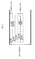
- a region in a thickness direction of the steel sheet employed in this specification will be described with reference to FIG. 1 .
- the terms '1/8 sheet thickness surface layer' and '1/4 sheet thickness center layer' indicate corresponding regions shown in FIG.1 .
- a region corresponding to '1/8 sheet thickness surface layer' is present on both surfaces of the steel sheet, but those having only one '1/8 sheet thickness surface layer' on any side can also be included in the scope of the present invention.
- the second phase which is the characteristic of the present invention is not necessarily uniformly dispersed in a whole area when distribution in a direction of the steel sheet is taken into consideration, and it may be unevenly distributed in the sheet thickness direction. It is rather better to form a multilayer constitution including a layer with many second phases and a layer with less second phases in a thickness direction, from the viewpoint of effect of the present invention. A mechanism for this is not clear, but it is believed that a layer with many second phases and a layer with less second phases restrict the deformation of one another thereby increasing the measure of work hardening, and thus a local deformation is controlled. This can be thought alternatively that an effect similar to a restricting relationship between the second phase and the matrix is occurring in macro-spaces.
- the volume fraction of the second phase (a volume fraction of 1/8 sheet thickness surface layer)/(a volume fraction of 1/4 sheet thickness center layer) ⁇ 10 is preferable, or regarding the number density of the second phase, (a volume fraction of 1/8 sheet thickness surface layer)/(a volume fraction of 1/4 sheet thickness center layer) ⁇ 10 is preferable.
- the ratios are preferably 20 or more, more preferably 50 or more, even more preferably 100 or more, even further preferably 200 or more.
- it is necessary to be careful not to form too many second phases in the surface layer part because it may cause a surface defect or may cause the sheet to break readily.
- the present invention applies only to a steel sheet having a sheet thickness of 0.400 mm or less. This is because there is no point of applying a technique limited to a uniform elongation to a steel sheet having a greater thickness as in the present invention because upon working, molding still takes place to a certain degree after the formation of constriction due to a local ductility.
- the technique can be used usefully to an extra thin steel sheet having a thickness of preferably 0.250 mm or less, more preferably 0.200 mm or less, even more preferably 0.150 mm or less.
- a preferred applicable material is a steel sheet satisfying a maximum strength ⁇ 350 MPa and HR30T Rockwell hardness ⁇ 54, according to a tensile test (specifically, a tensile test carried out with the use of a tensile test specimen having a parallel part of 25 mm wide and 60 mm long under conditions of a distance between marks of 50 mm and a deformation rate of 5 mm/min) carried out with the use of a JIS5 tensile test specimen. More preferred is a steel sheet satisfying a maximum strength 400 ⁇ MPa and HR30T Rockwell hardness ⁇ 57, and even more preferred is a steel sheet satisfying a maximum strength ⁇ 450 MPa and HR30T Rockwell hardness ⁇ 61.
- the steel sheet of the present invention provides the characteristic in satisfying (uniform elongation)/(local elongation) ⁇ 1.0, according to a tensile test carried out with the use of a JIS5 tensile test specimen.
- the ratio is preferably 1.5 or more, more preferably 2.0 or more, even more preferably 3.5 or more, even further preferably 5.0 or more.
- the steel satisfies yield stress/maximum strength ⁇ 0.9, more preferably 0.8 or less, even more preferably 0.7 or less, even further preferably 0.6 or less, according to a tensile test carried out with the use of a JIS5 tensile test specimen.
- a preferred embodiment includes rolling and elongating an oxide by rolling in a hot-rolling step to be modified into a preferable form. In order to do this, a certain degree of work amount is required, and a thickness of a steel slab subjected to casting is set to preferably 50 mm or more, more preferably 150 mm or more. In order for the rolled and elongated oxide to have an appropriate size, a size of the oxide before subjected to rolling and elongation is preferably between 10 ⁇ m and 25 ⁇ m.
- the oxide is rolled and elongated by rolling and accordingly an acicular oxide which is preferable for the present invention is obtained.
- the oxide is hardly rolled and elongated at a temperature lower than 1000°C, such as at about 900°C or below, it partly cracks, and oxides having a reasonable acicular morphology disperse at an appropriate interval in the steel sheet.
- a temperature control upon hot-rolling a strain amount for each temperature region and also a control of strain rate so as to control softening of work-hardened ferrite, also become important.
- a preferable effect as in the case of oxide can be obtained.
- a case where a carbide is used as the characteristic second phase will be illustrated.
- a carbide having a more preferable configuration from C and additive elements which are previously contained in a steel by heat treatment or the like in manufacturing processes.
- a method of using carburization will be illustrated as the more preferable configuration.
- the condition includes after cold rolling, performing a carburization treatment at a temperature ranging between 600 and 700°C under a condition of giving ⁇ (carburization time (sec)) * (carburization temperature (°C)) ⁇ / ⁇ (carburizing gas concentration (%)) * (cooling rate in carburization treatment (°C/sec)) ⁇ ⁇ 20, simultaneously with or after a recrystallization annealing, thereby increasing a C amount by 0.0002% or more. If the temperature is out of above range, carburization efficiency decreases at a low temperature side, and on the contrary if the temperature is too high, the configuration of the carbide may be easily isotropic.
- the preferable configuration of the second phase can be achieved. Basically, since the carbide can be sufficiently grown with a gradual cooling treatment at a high temperature for a long time while suppressing the growth of the deposition nucleus of the carbide in a low C concentration, the development of the anisotropic second phase is remarkable.
- the carburization condition it is preferable to control the value of the above formula such that only surface part is carburized.
- This value may also depend on the plate thickness, and is preferably 500 or less, more preferably 200 or less.
- the condition of atmosphere including the type of carburizing gas may be the generally known condition.
- the carburizing method is not limited to the gas carburization illustrated herein, and the generally known carburizing method can be applied.
- 0.0002 % or more which is the increased amount of C may seem to be very small as the increased amount, but this amount is sufficient for exhibiting the effect of the present invention in consideration of the increased amount at a surface layer of the steel plate in an extra thin material.
- the condition includes after cold rolling, performing a nitriding treatment at a temperature ranging between 600 and 700°C under a condition of giving ⁇ (nitriding time (sec)) * (nitriding temperature (°C)) ⁇ / ⁇ (nitriding gas concentration (%))* (cooling rate in nitriding treatment (°C/sec)) ⁇ ⁇ 20, simultaneously with or after a recrystallization annealing, thereby increasing an N amount by 0.0002% or more.
- the condition of atmosphere including the type of nitriding gas may be the generally known condition.
- the nitriding method is not limited to the gas nitration illustrated herein, and the generally known nitriding method can be applied similar to the case of carburization.
- the intermetallic compound is used as the second phase
- the cooling speed is too rapid, the nucleus generation frequency of the intermetallic compound becomes high and the anisotropic growth is not occurred so that the isotropic intermetallic compound is formed with high density.
- the manufacturing methods of various second phases illustrated herein are different depending on elements forming the objective second phase and amounts thereof and not limited to the above described ranges. If the kind of elements forming the second phase, the type and amount of the second phase to be formed, and the directionality of the configuration to be controlled are known, suitable conditions can be sought within in a general metallurgical category and it is not difficult for a person skilled in the art to identify the conditions through several trial.
- a re-cold rolling may be performed after a recrystallization annealing for the hardness adjustment or plate thickness adjustment.
- the rolling reduction ranging from about several % near the skin-pass which is performed for the shape adjustment up to 50% or more similar to a cold rolling is practically used.
- the effect of the present invention is not damaged.
- the rolling reduction is too high, an absolute value of uniform elongation becomes small.
- a work-hardened amount in a uniform elongation region becomes small so that it is not a preferable method considering the application of the effect of the present invention.
- the rolling reduction is preferably 30% or less, more preferably 20% or less, further preferably 10% or less, and most preferably 3% or less.
- the effect of the present invention does not depend on the heat history and manufacturing history, after component adjustment and before annealing. Since a slab in case of performing a hot rolling is not limited to a manufacturing method such as a continuous casting process and does not depend on the heat history until reaching a hot rolling, the effect of the present invention can be achieved even with a slab reheating method, CC-DR method directly heat rolling the cast slab without reheating, and a thin slab casting omitting the rough rolling or the like. Furthermore, the effect of the present invention can be obtained even with a dual phase region rolling having a finishing temperature of ⁇ + y phases and a continuous hot rolling which rolls by connecting a rough bar, without depending on a hot rolling condition.
- the steel of the present invention is particularly preferable when it is used for a member having a welded portion, because a uniform deformation property in a heat-affected portion is improved and the occurrence of a constricted part is suppressed.
- the steel plate of the present invention can be used with any surface treatment. In the scope of the present invention, the steel plate is not damaged by applying the surface treatment.
- the surface treatment includes applying tin, chrome (tin-free), Ni, zinc, aluminum or the like which is generally performed for a metal plating.
- the effect of the present invention can be obtained with respect to a primitive plate for a laminate steel plate coated with an organic film which is used recently.
- the steel plate of the present invention can be generally used for electric apparatuses, electronic components, architectural materials or metal containers, and also can be used in other applications if the use thereof includes the task similar to the above-described matter.
- a hard extra-thin material exhibiting more uniform elongation capacity while preventing a local deformation (constriction) from occurring up to a high strained region, even if the same strength and the same total elongation are employed, can be obtained.
Landscapes
- Chemical & Material Sciences (AREA)
- Engineering & Computer Science (AREA)
- Materials Engineering (AREA)
- Mechanical Engineering (AREA)
- Metallurgy (AREA)
- Organic Chemistry (AREA)
- Physics & Mathematics (AREA)
- Thermal Sciences (AREA)
- Crystallography & Structural Chemistry (AREA)
- Heat Treatment Of Sheet Steel (AREA)
- Solid-Phase Diffusion Into Metallic Material Surfaces (AREA)
Abstract
Description
- The present invention relates to a thin steel sheet having a sheet thickness of 0.400 mm or less which also includes a surface treated steel sheet used for electric equipments, electronic parts, building materials and metallic containers, and to a method of manufacturing the same.
The present application claims the benefit of priority to Japanese Patent Application No.2006-102766 - A thin steel sheet having a sheet thickness of 0.400 mm or less has been used for various purposes such as for electric equipments, electronic parts, building materials and metallic containers, and a process of making a steel sheet more thin has been carried out to lower the cost of raw material. When it is made thin, a member employing such material accordingly causes decrease in its strength, and thus hardening of material is also generally required at the time of thinning the material. One of obvious problem occurring in such an extra thin and hard material is deterioration in formability. In particular, contrary to a thick material used for automobiles and the like, a thin material immediately causes breakage when constriction is occurred, and thus it is extremely important to give a uniform deformation. According to a tensile test which is generally applied for evaluating characteristics of a steel sheet, it means that a sheet has to be hardened without turning down a uniform elongation. Among the thin materials, for a steel sheet for containers for which a heavy working such as drawing, ironing or tensile elongation is performed, methods disclosed in
Patent Documents 1 to 3 or the like have been proposed to assure the formability. - However, these methods are not particularly focusing on a uniform elongation, and although high ductility (total formability) is provided, the ductility is increased more likely by a local elongation. Therefore, in practice, they do not give answers to problems mentioned in this application, such as defect in surface quality due to breakage or constriction.
- [Patent Document 1] Japanese Unexamined Patent Application, First Publication No.
H02-118026 - [Patent Document 2] Japanese Unexamined Patent Application, First Publication No.
H03-257123 - [Patent Document 3] Japanese Unexamined Patent Application, First Publication No.
H10-72640 - An object of the present invention is to prevent breakage or constriction caused by lack of uniform deformation, which is a problem occurring upon using an extra thin, hard material. In specific, an object is to, for deterioration in elongation due to a hardening of material, consider the deterioration of local elongation on a priority basis so as to assure a uniform elongation and to prevent a local deformation (constriction) up to a high strained region even for the same total elongation. Furthermore, another object of the present invention is to make clear a material condition, and to provide a steel sheet employing such the condition and a manufacturing method thereof.
- The present inventors have carried out a research on dispersing various second phases in a steel sheet for hardening the steel sheet. In specific, it belongs to a category of precipitation hardening and transformation hardening, and a material can be hardened by dispersing a second phase, according to which, of course, the formability deteriorates. However, after experimentation, the inventors found out that when a second phase having a specific morphology is dispersed in a steel sheet, hardening is achieved while preventing deterioration in uniform elongation. In addition, the inventors have in detail investigated morphology, amount and kind of second phase and also scopes of steel sheet materials for obtaining preferable properties, and thus completed the present invention. Key points of the present invention are as shown below.
- (1) Controlling a morphology of the second phase: so as to give highly anisotropic acicular ones.
- (2) Controlling a size of the second phase: so as to give a relatively larger sized ones than that of usual precipitates.
- (3) Controlling a number density of the second phase: so as to give a relatively thin distribution.
- (4) A matrix is provided as a Fe ferrite phase, and an orientation of the second phase is arranged in a specific direction to the matrix.
- The inventors of the present invention have carried out keen investigation based on above-mentioned technical ideas, and as a result, they have achieved the present invention. Key points thereof are as described in the contents shown below.
- (1) A hard extra-thin steel sheet having a sheet thickness of 0.400 mm or less, including: by mass%, C: 0 to 0.800%; N: 0 to 0.600%; Si: 0 to 2.0%; Mn: 0 to 2.0%; P: 0 to 0.10%; S: 0 to 0.100%; Al: 0 to 3.0%; and O: 0 to 0.200%. The hard extra-thin steel sheet contains 0.05% or more, by volume fraction, of a second phase having an average major axis of 0.10 µm or greater and an average minor axis of 0.05 µm or greater and satisfying average major axis/average minor axis ≥ 2.0.
- (2) The hard extra-thin steel sheet according to (1) above, which further contains at least one of: Ti: 0 to 4.00%; Nb: 0 to 4.00%; REM: 0 to 4.00%; B: 0 to 0.0300%; Cu: 0 to 8.00%; Ca: 0 to 1.00%; Ni: 0 to 8.00%; and Cr: 0 to 20.00%.
- (3) The hard extra-thin steel sheet according to (1) above, wherein a number density of the second phase having an average major axis of 0.5 µm or greater and an average minor axis of 0.1 µm or greater and satisfying average major axis/average minor axis ≥ 2.0 is 0.01 pieces/µm2 or more.
- (4) The hard extra-thin steel sheet according to (1) above, wherein a number density of the second phase having an average major axis of 0.5 µm or greater and an average minor axis of 0.1 µm or greater and satisfying average major axis/average minor axis ≥ 2.0 is 0.001 pieces/µm2 or more.
-
- (5) The hard extra-thin steel sheet according to (1) above, wherein a main phase is a ferrite phase of Fe and a volume fraction of which is 80% or more.
- (6) The hard extra-thin steel sheet according to (1) above, wherein a direction of the average major axis of the second phase having an average major axis of 0.5 µm or greater and an average minor axis of 0.1 µm or greater and satisfying average major axis/average minor axis ≥ 2.0 is in a <100> orientation or <110> orientation of an Fe phase that is in contact with the second phase.
- (7) The hard extra-thin steel sheet according to (1) above, wherein the second phase having an average major axis of 0.5 µm or greater and an average minor axis of 0.1 µm or greater and satisfying average major axis/average minor axis ≥ 2.0 is a simple substance of or a composite compound of oxide, sulfide, carbide, nitride or an intermetallic compound.
-
- (8) The hard extra-thin steel sheet according to (7) above, wherein the second phase having an average major axis of 0.5 µm or greater and an average minor axis of 0.1 µm or greater and satisfying average major axis/average minor axis ≥ 2.0 is an oxide including one or two kind(s) of Fe, Mn, Si, Al, Cr, REM, Ti and Nb.
- (9) The hard extra-thin steel sheet according to (7) above,
wherein the second phase having an average major axis of 0.5 µm or greater and an average minor axis of 0.1 µm or greater and satisfying average major axis/average minor axis ≥ 2.0 is a sulfide including one or two kind(s) of Ti, Mn, Cu, Ca and REM. - (10) The hard extra-thin steel sheet according to (7) above, wherein the second phase having an average major axis of 0.5 µm or greater and an average minor axis of 0.1 µm or greater and satisfying average major axis/average minor axis ≥ 2.0 is a carbide including one or two kind(s) of Fe, Ti, Nb, Si and Cr.
-
- (11) The hard extra-thin steel sheet according to (7) above, wherein the second phase having an average major axis of 0.5 µm or greater and an average minor axis of 0.1 µm or greater and satisfying average major axis/average minor axis ≥ 2.0 is a nitride including at least one or two kind(s) of Fe, Ti, Nb, Al, B and Cr.
- (12) The hard extra-thin steel sheet according to (7) above, wherein the second phase having an average major axis of 0.5 µm or greater and an average minor axis of 0.1 µm or greater and satisfying average major axis/average minor axis ≥ 2.0 is an intermetallic compound including at least one or two kind(s) of Fe, Ti, Nb, Al, Si and Mn.
- (13) The hard extra-thin steel sheet according to (1) above,
-
- (14) The hard extra-thin steel.sheet according to (1) above, wherein a number density of the second phase having an average major axis of 0.5 µm or greater and an average minor axis of 0.1 µm or greater and satisfying average major axis/average minor axis ≥ 2.0 satisfies (a number density of 1/8 sheet thickness surface layer)/(a number density of 1/4 sheet thickness center layer) ≥ 10.
- (15) The hard extra-thin steel sheet according to (1) above, which satisfies maximum strength ≥ 350 MPa and HR30T Rockwell hardness ≥ 54, according to a tensile test carried out with the use of a tensile test specimen having a parallel part of 25 mm wide and 60 mm long with a distance between marks of 50 mm at a deformation rate of 5 mm/min.
- (16) The hard extra-thin steel sheet according to (1) above, which satisfies uniform elongation/local elongation ≥ 1.0 according to a tensile test carried out with the use of a tensile test specimen having a parallel part of 25 mm wide and 60 mm long with a distance between marks of 50 mm at a deformation rate of 5 mm/min.
-
- (17) The hard extra-thin steel sheet according to (1) above, which satisfies yield stress/maximum strength ≤ 0.9 according to a tensile test carried out with the use of a tensile test specimen having a parallel part of 25 mm wide and 60 mm long with a distance between marks of 50 mm at a deformation rate of 5 mm/min.
- (18) A method of manufacturing the hard extra-thin steel sheet according to (8) above, which includes: upon hot rolling a bloom of steel having a thickness of 50 mm or more and containing oxide with an average diameter of 10µm to 25 µm, at 600°C or above, performing rolling at a total real strain of 0.4 or more under conditions of 1,000°C or above and a strain rate of 1/sec or more; and then performing rolling at a total real strain of 0.7 or more under conditions of 1,000°C or less and a strain rate of 10/sec or more.
- (19) A method of manufacturing the hard extra-thin steel sheet according to (9) above, which includes: upon hot rolling a bloom of steel having a thickness of 50 mm or more and containing sulfide with an average diameter of 10µm to 25 µm, at 600°C or above, performing rolling at a total real strain of 0.4 or more under conditions of 1,000°C or above and a strain rate of 1/sec or more; and then performing rolling at a total real strain of 0.7 or more under conditions of 1,000°C or less and a strain rate of 10/sec or more.
-
- (20) A method of manufacturing the hard extra-thin steel sheet according to (10) above, which includes, after cold rolling, performing a carburization treatment at a temperature ranging between 600 and 700°C under a condition of giving {(carburization time (sec)) * (carburization temperature (°C))}/{(carburizing gas concentration (%))* (cooling rate in carburization treatment (°C/sec))} ≥ 20, simultaneously with or after a recrystallization annealing, thereby increasing a C amount by 0.0002% or more.
- (21) A method of manufacturing the hard extra-thin steel sheet according to (11) above, which includes, after cold rolling, performing a nitriding treatment at a temperature ranging between 600 and 700°C under a condition of giving {(nitriding time (sec)) * (nitriding temperature (°C))}/{(nitriding gas concentration (%))* (cooling rate in nitriding treatment (°C/sec))} ≥ 20, simultaneously with or after a recrystallization annealing, thereby increasing an N amount by 0.0002% or more.
- (22) A method of manufacturing the hard extra-thin steel sheet according to (12) above, which includes performing cooling from a temperature of 900°C or above for the step of manufacturing a steel sheet, wherein cooling from 900°C down to 500°C is performed at a cooling rate of 20°C/sec or lower, thereby increasing a volume fraction of the intermetallic compound by 2.0-fold or more.
- The present invention relates to a thin steel sheet having a sheet thickness of 0.400 mm or less and a manufacturing method thereof. As a part of manufacturing method of an enameling steel sheet, there is a conventional technique in which a hot rolling condition is limited thereby controlling the morphology of oxide.
However, rolling and elongation of oxide in the present invention completely differs from those provided with a limit of hot rolling condition for an enameling steel sheet. More specifically, it had been very difficult to get an idea to put a rolled and elongated oxide into practical use for a thin steel sheet aimed by the present invention, according to an extension technique provided with a limit of hot rolling condition for an enameling steel sheet. These will be explained in detail below. - In general, inclusion of oxide in a thin steel sheet as for the present invention is controlled because it is an extremely unfavorable substance. This is because deformation concentrated around the oxide gives highly sensitive effect in breaking a base material as the base material itself is thin.
A good example can be shown by flange formability in a process of manufacturing cans. In regard to a steel material used for such purpose, an oxide amount is strictly controlled and its production is given at a very low level. An adverse effect of oxide on a thin material does not just stay on as the oxide problem, and when a rolled and elongated oxide as in an enameling steel sheet cracks in a cold rolling process and forms voids therearound, those voids give a cutting effect, thereby causing a further deterioration in formability of the base material.
Therefore, in the past, it was impossible to get an idea to put an oxide, even more a rolled and elongated oxide that may crack in cold rolling, into practical use for the purpose of improving the property for a thin material aimed by the present invention. - A technical difference in regard to a manufacturing method of enameling steel sheet and the present invention are mentioned as follows.
First, in a production of enameling steel sheet, an oxide is temporarily rolled and elongated at a hot rolling step but the oxide cracks in the following cold rolling step thereby forming many voids around the cracked oxide. All oxides in an end product are finely cracked and are in an isotropic form. - In contrast, in the present invention, the oxide has to be a rolled and elongated oxide at a final stage, and thus a hot rolling step is employed as a way for this. In other words, an oxide rolled and elongated under hot rolling is still kept as a rolled and elongated oxide even after the cold rolling and annealing, and an anisotropic form is necessarily maintained to an end product. When the same condition is employed for a hot rolling, this difference may be fundamentally exhibited by difference in the composition of oxides. In specific, for an enameling steel sheet, a compounded form of relatively soft Mn-containing oxide with hard Nb-, B-containing oxide works preferably in accelerating cracking. Meanwhile, for steel of the present invention, it is preferable that oxide be provided as a homogeneous substance and not as a compounded product including oxides of different composition, so as to give a uniform deformation at the time of cold rolling and avoid cracking.
- Even if oxide is temporarily rolled and elongated as in an enameling steel sheet, if the oxide becomes isotropic by cracking afterwards, work hardenability which is the characteristic of the present invention, excellent uniform elongation resulted therefrom, specifically a control effect on local deformation cannot be exhibited at all.
As explained above, even if a technique of manufacturing an enameling steel sheet is understood, it is not easy, even for a person skilled in the art, to apply the technique of including a large amount of oxide to a target steel of the present invention and to a use application, so as to investigate the effect of its morphology.
The steel of the present invention is invented on the basis of new findings such as when an oxide is rolled and elongated to a specific form and maintained as it is, a work hardening behavior thereof dramatically changes, and when a local deformation is strongly controlled, it well acts on a practical elongation capacity even in the case of a thin steel sheet. - According to the present invention, a hard, extra thin material exhibiting more uniform elongation capacity up to a high strained region while preventing a local deformation (constriction) from occurring, even if the same strength and the same total elongation are employed, can be obtained. Thus, it becomes possible to prevent problems occurred when a thin material is used, such as breakage due to a lack of uniform deformation and a generation of constriction.
-
-
FIG 1 is a diagram showing a region in a thickness direction of a hard extra-thin steel sheet of the present invention. - Hereinafter, the present invention will be described in more detail.
First, components will be explained. All the components are in mass%. The C amount is set to 0.800% or less to avoid deterioration in formability. The amount is preferably 0.100% or less, more preferably 0.060% or less. Particularly, in case of using carbide as the second phase that provides the characteristic of the present invention, the amount is preferably from 0.0050 to 0.040%, more preferably from 0.0080 to 0.030%. In the steel of the present invention in which a material strength is increased by dispersion of various second phases, the content of C to be needed from the viewpoint of assuring the strength or the like may be low. The required strength can still be achieved at the C content of 0.0050% or less. The content of 0.0030% or less, as well as 0.0015% or less can also be employed. From the point of maintaining high drawability by improving an r value, it is preferable for the C amount to be small. - As in the case of C, the N amount is also set to 0.800% or less to avoid deterioration in formability. The amount is preferably 0.100% or less, more preferably 0.060% or less. Particularly, in case of using nitride as the second phase that provides the characteristic of the present invention, the amount is preferably from 0.0050 to 0.040%, more preferably from 0.0080 to 0.030%. In the steel of the present invention in which a material strength is increased by dispersion of various second phases, the content of N to be needed from the viewpoint of assuring the strength or the like may be low. The required strength can still be achieved at the N content of 0.0050% or less. The content of 0.0030% or less, as well as 0.0015% or less can also be employed. From the point of maintaining high drawability by improving an r value, it is preferable for the N amount to be small.
- Si is set to 2.0% or less because at a too high content, formability or surface treatment property deteriorates. However, in the steel of the present invention, when oxide is used as the second phase, remaining of oxygen in the steel may become difficult or a rolled and elongated oxide which being the preferred characteristic for the present invention may be hardly obtained, as described later. In addition, when carburization or nitriding is carried out for forming the second phase, there may be a case where C or N entered in the steel forms coarse Si carbide or Si nitride in a crystalline grain boundary and thus causing brittle cracks. In order to avoid such the negative effects, the Si content may have to be 1.5% or less, further 1.0% or less. In particular, from the point of maintaining high formability, it is preferable for the Si amount to be small. The formability can be improved by setting the content to be 0.5% or less, further 0.1% or less, or even further 0.07% or less.
- Mn is set to 2.0% or less because at a too high content, formability or surface treatment property deteriorates. Meanwhile, in the steel of the present invention, when oxide is used as the second phase, as described later, a rolled and elongated oxide which is preferable for the present invention is readily obtained. In addition, when sulfide is used for forming the second phase, a rolled and elongated sulfide can be readily obtained, and thus this element is useful. Consequently, a preferred range of Mn is from 0.05 to 1.0%, preferably from 0.15 to 0.8%, and even more preferably from 0.25 to 0.7%.
P is set to 0.10% or less because at a too high content, not only the formability deteriorates, but also when carburization or nitriding are performed for forming the second phase, the carburization property or nitriding property of the steel sheet is obstructed. From the point of maintaining high formability, it is preferable for the P amount to be small. The formability can be improved by setting the content to be 0.05% or less, further 0.01% or less. - S is set to 0.100% or less or otherwise deteriorates heat-rolling ductility and becomes the cause of obstructing the casting or hot rolling. However, when a large amount of Mn, Cu, TI, REM or the like is added and a sulfide thereof is used as the second phase that is needed for the present invention, deterioration in hot-rolling ductility is small and thus this element is useful. Consequently, a preferred range of S is from 0.015 to 0.080%, preferably from 0.025 to 0.070%, and even more preferably from 0.035 to 0.060%.
- Al is set to 3.0% or less because at a high content, there may be a problem such as casting becomes difficult or defects on the surface increase. However, since Al is a strong deoxidizing element, remaining of oxygen in the steel becomes difficult when oxide is used as the second phase. Thus, the Al content may sometimes have to be 0.010% or less, further 0.005% or less, even further 0.002% or less, or particularly further 0.001% or less. Alternatively, Al may serve as an element of forming an intermetallic compound such as Ni3Al, and exhibits a preferable effect on the dispersion of the second phase needed for the present invention. The content may vary depending on the kind or amount of metallic element forming a compound together with Al, but in this case, the Al content is preferably 1.0% or more, further 1.5% or more, even further 2.0% or more.
- O is preferably set to 0.010% or less when an oxide is not used as the second phase that provides the characteristic of the present invention because deoxidation via Al, Si, Ti or the like occurs. It is set so because when oxide in the steel becomes an isotropic form (spherical) which gives no effect for exhibiting advantages of the present invention, this element readily becomes the cause of cracking. Even in the case where an oxide is used as a useful second phase, excessive oxide may readily become the cause of cracking, and thus the O content has to be set to 0.200% or less, preferably 0.010 to 0.100%, more preferably 0.020 to 0.080%, even more preferably 0.030 to 0.050%.
- Next, elements which may be added as necessary will be explained.
Ti causes the increase of recrystallization temperature of the steel sheet, and significantly deteriorates passability of extra thin steel sheet subjected in the present invention in annealing. Therefore, the Ti content is set to be 4.00% or less. When a Ti compound is not used as the second phase that provides the characteristic of the present invention, there is no need of adding Ti, and the content may be 0.04% or less, more preferably 0.01% or less. Meanwhile, oxides, sulfides, carbides, nitrides and intermetallic compounds, of Ti can be used as the second phase that provides the characteristic of the present invention. The content may vary depending on the kind or amount of an element forming the compound, but a sufficient effect can be exhibited at a content of 0.06% or more. More preferred is 0.100% or more. - Nb has the same effect as Ti that it causes the increase of recrystallization temperature, and significantly deteriorates passability of extra thin steel sheet subjected in the present invention in annealing. Therefore, the Nb content is set to be 4.00% or less. When an Nb compound is not used as the second phase that provides the characteristic of the present invention, there is no need of adding Nb, and the content may be 0.04% or less, more preferably 0.01% or less. Meanwhile, oxides, sulfides, carbides, nitrides and intermetallic compounds, of Nb can be used as the second phase that provides the characteristic of the present invention. The content may vary depending on the kind or amount of an element forming the compound, but a sufficient effect can be exhibited at a content of 0.06% or more. More preferred is 0.100% or more.
- REM also has the same effect as Ti and Nb, and as it is an expensive element, the content is set to be 4.00% or less. When a REM compound is not used as the second phase that provides the characteristic of the present invention, there is no need of adding REM, and the content may be 0.04% or less, more preferably 0.01 % or less. Meanwhile, oxides, sulfides, carbides, nitrides and intermetallic compounds, of REM can be used as the second phase that provides the characteristic of the present invention. The content may vary depending on the kind or amount of an element forming the compound, but a sufficient effect can be exhibited at a content of 0.06% or more. More preferred is 0.100% or more.
- B also has the same effect as Ti and Nb. However, its ability to form carbonitride is less than that of Ti or Nb although it may vary depending on the added amount. When B is added simultaneously with those elements for the purpose of forming carbide or nitride as the second phase, it causes the increase of recrystallization temperature of the steel sheet, and significantly deteriorates passability of extra thin steel sheet subjected in the present invention in annealing. Therefore, B is useful in the case where Ti or Nb content is small. The upper limit is set to 0.0300% because an excessive amount results in notable cracks in a steel slab upon casting. When a B compound is not used as the second phase that provides the characteristic of the present invention, there is no need of adding B, and the content may be 0.0020% or less, more preferably 0.0010% or less. Meanwhile, oxides, sulfides, carbides, nitrides and intermetallic compounds, of B can be used as the second phase that provides the characteristic of the present invention. The content may vary depending on the kind or amount of an element forming the compound, but a sufficient effect can be exhibited at a content of 0.0040% or more. More preferred is 0.0100% or more.
- Cu is set to 8.00% or less because at a too high content, not only the recrystallization temperature significantly increases, but also defects in surface quality are occurred and formability or surface treatment property deteriorates. Meanwhile, in the steel of the present invention, a metallic Cu phase, an intermetallic compound phase or the like can also be used as the second phase. Furthermore, when a sulfide is used for forming the second phase, a rolled and elongated sulfide is readily obtained and thus this is element is useful. Consequently, a preferred range of Cu is from 0.10 to 4.00%, more preferably from 0.20 to 3.00%, even more preferably from 0.30 to 2.50%.
Ca is a useful element for the steel of the present invention as when a sulfide is used as the second phase, a rolled and elongated sulfide can be readily obtained. However, Ca is usually hardly contained in a large amount in the steel due to high reactivity, and thus the amount is set to 1.00% or less. A preferred range is from 0.01 to 0.50%, more preferably from 0.05 to 0.30%. - Ni is an expensive element, and its amount is set to 8.00% or less. In the present invention, Ni serves as an element of forming an intermetallic compound such as Ni3Al, and it exhibits a favorable effect for the dispersion of the second phase needed for the present invention. The amount may vary depending on the kind or amount of metallic element forming a compound together with Ni, but is preferably 1.0% or more, further 1.5% or more, even further 2.0% or more.
Cr is also an expensive element, and its amount is set to 20.00% or less. When a Cr compound is not used as the second phase that provides the characteristic of the present invention, there is no need of adding Cr, and the amount may be 0.06% or less, more preferably 0.02% or less. Meanwhile, oxides, sulfides, carbides, nitrides and intermetallic compounds, of Cr can be used as the second phase that provides the characteristic of the present invention. The amount may vary depending on the kind or amount of an element forming the compound, but a sufficient effect can be exhibited at a content of 0.10% or more. More preferred is 0.50% or more, even more preferred is 1.5% or more, and further more preferred is 2.50% or more. - The content of elements other than those mentioned above is not particularly limited, but Sn, Sb, Mo, Ta, V and W are added each by an amount of 0.10% or less which in total giving a sum of amounts of 0.50% or less, so as to impart properties not provided by the present invention. With this amount, the effect of the present invention is not interfered in any way. However, it is necessary to give an attention as there may be a case where those elements form a coarse compound having an isotropic form and thus deteriorating the formability. If there is no particular purpose, the amount of each element is preferably set to 0.010% or less and a sum of amounts of 0.050% or less, more preferably set to 0.0020% or less and a sum of amounts of 0.0050% or less, and even more preferably set to 0.0010% or less and a sum of amounts of 0.0030% or less.
- Next, the second phase which is the most important factor in the present invention will be described. First, an observation or the like of the second phase will be described. The observation method of the second phase is not particularly limited to those defined in the present invention. The morphology can be observed directly by a physical measuring equipment such as an electron microscope which allows the observation of micro regions. In case of observing a relatively large size, an observation can be made by a high-power optical microscope. With an optical microscope or a scanning electron microscope (SEM), steel sheets a cross section of which is polished and further subjected to etching can be observed, and with a transmission electron microscope (TEM), a thin film as well as an extracted replica obtained by a SPEED method, or the like can be observed. In addition, a residue in which a matrix is dissolved by an electrolysis extraction may also be observed. The observed second phase can be identified by EDX or electron beam diffraction patterns, but the technique is not limited to these and any analytical instrument currently providing a significantly improved performance may also be used. The point is that it is fine as long as a form, size and number density, or if necessary a kind, of the second phase can be determined according to an appropriate method. It is thought that there may be a case where a full identification is difficult in some kinds that provide a composition of various phases. However, since the effect of the present invention is achieved regardless of the kind by dispersing a second phase in a specific morphology, those difficult to be identified can also be included in the present invention. In regard to the volume fraction and the number density, when more fine nitrides are considered using more advanced analytical instrument, these values may be increased. However, the effect of the present invention still can be distinguished when a size of 0.02 µm or greater is used as an object with the use of a physical instrument of normal level.
- The present invention has a feature of containing 0.05% or more of the second phase observed as above, having an average major axis of 0.10 µm or greater and an average minor axis of 0.05 µm or greater and satisfying average major axis/average minor axis ≥ 2.0. The size of average major axis is preferably 0.20 µm or greater, more preferably 0.50 µm or greater, even more preferably 1.00 µm or greater, even more preferably 2.00 µm or greater, even more preferably 5.00 µm or greater. However, if a too large second phase is existed, it becomes the cause of breakage in an early stage of work thereby significantly deteriorating the ductility. Therefore, the size is set preferably to 30 µm or less, more preferably to 20 µm or less. However, if the phase number is extremely small, a possibility of giving an adverse effect is very small even if the phase is large, and thus it cannot be said that an existence of the phase having a greater size than those mentioned above is outside the range of the present invention. The average major axis/average minor axis is preferably 3.0 or more, more preferably 5.0 or more, even more preferably 8.0 or more. The volume fraction is preferably 0.1 % or more, more preferably 0.3% or more, even more preferably 1.0% or more, even further preferably 2.0% or more. However, if the amount of the second phase is too large, in some cases, breakage in an early stage of work may occur thereby significantly deteriorating the ductility. Therefore, the fraction is set preferably to 20% or less, more preferably to 10% or less.
- In regard to the number density of the second phase, 0.01 pieces/µm2 or more when a cross section of the steel sheet is observed and 0.001 pieces/µm2 or more when a spatial dispersion is measured such as when a thin film is observed with extraction replica or transmission electron microscope, will exhibit a remarkable effects of the present invention. In the case of a cross-section observation, the number density is preferably 0.03 pieces/µm2 or more, more preferably 0.1 pieces/µm2 or more, even more preferably 0.3 pieces/µm2 or more. In the case of a spatial measurement, the number density is preferably 0.003 pieces/µm2 or more, more preferably 0.01 pieces/µm2 or more, even more preferably 0.03 pieces/µm2 or more. The number density correlates with the above-mentioned size and volume fraction, and it is necessary to be careful not to extremely increase or decrease the density within the scope of not deteriorating the formability as in the size and volume fraction.
- As such, a mechanism of controlling the occurrence of local deformation by controlling the morphology of the second phase is not clear, but an attempt is made below.
The second phase in the present invention is harder than an Fe phase provided as a matrix, and thus a deformation of matrix occurs on a priority basis upon a deformation of steel sheet. In addition, since the deformation of matrix is restricted by the second phase, work-hardening of the matrix becomes significant. Consequently, it is believed that the strain transmissibility improves and the deformation continues while being covered in a larger area thereby giving a higher uniform elongation. When an anisotropic second phase is dispersed, it is believed that a restriction degree in the matrix becomes greater than that in a general isotropic second phase. Aside from this, it can be thought that a binding state between a strong anisotropic second phase and a matrix becomes weak, and thus the interface undergoes a sliding due to the deformation and additionally forms many voids, thereby allowing deformation. Accordingly, it is thought that a state in which deformation of a matrix itself is controlled is shown up to a higher strained region and thus a uniform deformation continues. In the steel of the present invention, there are many cases where a local formability is lowered at the same time of providing a large measure of work hardening, but a mechanism to fully explain the phenomenon is not yet clear. - The deformation of matrix that is a main phase making the most of the sheet by volume is definitely the reason for a uniform deformation in the steel of the present invention and not the second phase. It is natural that the main phase is Fe, and a main phase in the present invention is supposed as a ferrite phase of Fe. Its volume fraction is preferably 80% or more. In general, a pearlite, bainite or martensite is known as the phase mainly composed of Fe, but in the present invention, as strengthening the sheet is achieved by a dispersion of second phase, the main phase is preferably a soft and uniform phase from the viewpoint of formability. The volume fraction is preferably 85% or more, more preferably 90% or more, so as to avoid deterioration in elongation capacity due to a formation of second phase in excess.
Furthermore, an orientation relationship of the second phase and the main phase is also an important matter. As already mentioned in the mechanism above, the effect of the present invention is believed to correlate with a binding state of Fe phase and the second phase. In relation to this, an average major axis of the second phase is preferably in a <100> orientation or a <110> orientation of the Fe phase that is in contact with the second phase. This orientation relationship can be determined by usual electron beam diffraction or the like. - A kind of second phase is described next. In the present invention, when the second phase is a simple substance of or a composite compound of oxide, sulfide, carbide, nitride or an intermetallic compound, a remarkable effect can be obtained. In the case of an oxide, oxides including one or two of Fe, Mn, Si, Al, Cr, REM, Ti and Nb can be employed. In the case of a sulfide, sulfides including one or two of Ti, Mn, Cu, Ca and REM can be employed. In the case of carbide, carbides including one or two of Fe, Ti, Nb, Si and Cr can be employed. In the case of a nitride, nitrides including one or two of Fe, Ti, Nb, Al, B and Cr can be employed. In the case of an intermetallic compound, intermetallic compounds including one or two of Fe, Ti, Nb, Al, Si and Mn can be employed. In regard to the carbide, a pearlite composition that is normally observed for steel, in specific, a layer composition including cementite and a ferrite phase generated due to a transformation of austenite at high temperature is excluded for the present invention as it cannot provide an effect of the present invention at all. As the metamorphic intermetallic compound, there are NiAl, Ni3Al, Ni3(Al, Ti), N2TiAl, Ni3Ti, Ni3Mo, Ni4Mo, Ni3Nb, Co3W, Fe2Mo, Fe2Ti, Fe2(Ni, Co) and the like.
Above-mentioned oxides, sulfides, carbides, nitrides and intermetallic compounds are a compound usually seen in a steel material, and a special compound is not necessarily employed. However, a special compound can still be formed to a morphology lying within the scope of the present invention. The kind of the phase is not limited to those mentioned above as only the representative elements are mentioned in the above. In addition, the second phase that exists in steel is not limited to one kind and a case where two or more kinds are combined is also included in the present invention. These may exist independently or may together form a composite compound. Moreover, a phase that is not included in the present invention from a morphological view can also be existed simultaneously. - The important matter is the morphological feature of the second phase. However, in reality, there is quite a difference in the effect depending on the second phase formed. This difference is thought to be affected by kind or amount of the second phase that can be formed in a steel sheet; a morphology difference that can be controlled by manufacture conditions as described later; and kind of the second phase itself that also correlates with a binding state with the matrix.
- Their effects are not fully classified yet, but from a phenomenon point of view, classification of preferred kind of the second phase and the element forming the second phase can be made as shown below. The kind can be ranked as follows: intermetallic compound>carbide ≈ nitride>oxide>sulfide. However, this order is made only by estimating the effect assuming that the morphology and the amount are the same, and there may be a case where assuring the amount or controlling the morphology is difficult depending on the manufacturing method or the kind of the second phase. Thus, this order is only for a rough indication. In regard to the effect of elements, the following points can be mentioned. In the case of oxide, preferred are those including Fe, Mn and REM; while Si, Al, Cr, Ti and Nb provide a small effect. In the case of sulfide, preferred are Mn, Ca and REM; while Ti and Cu provide a small effect. In the case of carbide, preferred are Cr, Ti and Si; while Fe and Nb provide a small effect. In the case of nitride, preferred are Fe, Ti, B and Cr; while Nb and Al provide a small effect. In the case of an intermetallic compound, preferred are Fe, Al, Si and Mn; while Ti and Nb provide a small effect.
- Now, a region in a thickness direction of the steel sheet employed in this specification will be described with reference to
FIG. 1 . The terms '1/8 sheet thickness surface layer' and '1/4 sheet thickness center layer' indicate corresponding regions shown inFIG.1 . Here, a region corresponding to '1/8 sheet thickness surface layer' is present on both surfaces of the steel sheet, but those having only one '1/8 sheet thickness surface layer' on any side can also be included in the scope of the present invention. It is relatively easy to give different nitride distribution to front and back of the sheet by modifying a manufacturing method, and a steel sheet having different front and back layers as such can also be included for the present invention. This is because an effect of improving a uniform formability which is the target of the present invention can still be achieved by one layer. For the volume fraction and the number density mentioned above, measurement values can be taken as data as long as they do not seem to be abnormal, and those satisfying requirements for the present invention in specific regions of 1/8 surface layer and 1/4 center layer can be satisfactorily employed. Herein, the '1/8 sheet thickness position' is also included in '1/8 sheet thickness surface layer'. - The second phase which is the characteristic of the present invention is not necessarily uniformly dispersed in a whole area when distribution in a direction of the steel sheet is taken into consideration, and it may be unevenly distributed in the sheet thickness direction. It is rather better to form a multilayer constitution including a layer with many second phases and a layer with less second phases in a thickness direction, from the viewpoint of effect of the present invention. A mechanism for this is not clear, but it is believed that a layer with many second phases and a layer with less second phases restrict the deformation of one another thereby increasing the measure of work hardening, and thus a local deformation is controlled. This can be thought alternatively that an effect similar to a restricting relationship between the second phase and the matrix is occurring in macro-spaces. In particular, it is possible to obtain a great part of the effect of the present invention by distributing the second phases intensively in a surface layer part of the steel sheet. In specific, regarding the volume fraction of the second phase, (a volume fraction of 1/8 sheet thickness surface layer)/(a volume fraction of 1/4 sheet thickness center layer) ≥ 10 is preferable, or regarding the number density of the second phase, (a volume fraction of 1/8 sheet thickness surface layer)/(a volume fraction of 1/4 sheet thickness center layer) ≥ 10 is preferable. The ratios are preferably 20 or more, more preferably 50 or more, even more preferably 100 or more, even further preferably 200 or more. However, it is necessary to be careful not to form too many second phases in the surface layer part because it may cause a surface defect or may cause the sheet to break readily.
- Next, characteristics of the steel sheet which to be the target of the present invention will be described. First, there is a limit that the present invention applies only to a steel sheet having a sheet thickness of 0.400 mm or less. This is because there is no point of applying a technique limited to a uniform elongation to a steel sheet having a greater thickness as in the present invention because upon working, molding still takes place to a certain degree after the formation of constriction due to a local ductility. The technique can be used usefully to an extra thin steel sheet having a thickness of preferably 0.250 mm or less, more preferably 0.200 mm or less, even more preferably 0.150 mm or less.
- Furthermore, even in the case of thin material, it is still possible to impart a certain degree of uniform elongation to a hard material, and thus the applicable scope of this technique includes a hard material. This is also because the second phase which provides the characteristic of the present invention causes hardening by quite a degree. A preferred applicable material is a steel sheet satisfying a maximum strength ≥ 350 MPa and HR30T Rockwell hardness ≥ 54, according to a tensile test (specifically, a tensile test carried out with the use of a tensile test specimen having a parallel part of 25 mm wide and 60 mm long under conditions of a distance between marks of 50 mm and a deformation rate of 5 mm/min) carried out with the use of a JIS5 tensile test specimen. More preferred is a steel sheet satisfying a maximum strength 400 ≥ MPa and HR30T Rockwell hardness ≥ 57, and even more preferred is a steel sheet satisfying a maximum strength ≥ 450 MPa and HR30T Rockwell hardness ≥ 61. In addition, the steel sheet of the present invention provides the characteristic in satisfying (uniform elongation)/(local elongation) ≥ 1.0, according to a tensile test carried out with the use of a JIS5 tensile test specimen. The ratio is preferably 1.5 or more, more preferably 2.0 or more, even more preferably 3.5 or more, even further preferably 5.0 or more. As mentioned before, it is also a characteristic of the present invention that the steel has a large measure of work hardening. The steel satisfies yield stress/maximum strength ≤ 0.9, more preferably 0.8 or less, even more preferably 0.7 or less, even further preferably 0.6 or less, according to a tensile test carried out with the use of a JIS5 tensile test specimen.
- Hereinbelow, one preferred example of the manufacturing method will be represented for each kind of the second phase in the steel of the present invention. First, a case where an oxide is used as a special second phase will be represented. A preferred embodiment includes rolling and elongating an oxide by rolling in a hot-rolling step to be modified into a preferable form. In order to do this, a certain degree of work amount is required, and a thickness of a steel slab subjected to casting is set to preferably 50 mm or more, more preferably 150 mm or more. In order for the rolled and elongated oxide to have an appropriate size, a size of the oxide before subjected to rolling and elongation is preferably between 10 µm and 25 µm. If the size is too small, rolling and elongation becomes difficult, and if the size is too big, a state of spatial dispersion after rolling becomes linear thus is not preferable from the viewpoint of exhibiting the effect of the present invention. Next, it is effective to perform rolling at a total real strain of 0.4 or more under conditions of 1,000°C or above and a strain rate of 1/sec or more; and then performing a rolling at a total real strain of 0.7 or more under conditions of 1,000°C and a strain rate of 10/sec or more. A mechanism for this is not clear, but it can be assumed as follows. At a high-temperature region of 1000°C, the oxide softens and gives a small hardness difference when compared with that of hardened ferrite. Therefore, the oxide is rolled and elongated by rolling and accordingly an acicular oxide which is preferable for the present invention is obtained. The oxide is hardly rolled and elongated at a temperature lower than 1000°C, such as at about 900°C or below, it partly cracks, and oxides having a reasonable acicular morphology disperse at an appropriate interval in the steel sheet. In order to appropriately roll, elongate and disperse in such a way, a temperature control upon hot-rolling, a strain amount for each temperature region and also a control of strain rate so as to control softening of work-hardened ferrite, also become important.
By applying the temperature, strain amount and strain rate conditions to the case of sulfide, a preferable effect as in the case of oxide can be obtained. - Next, a case where a carbide is used as the characteristic second phase will be illustrated.
In this case, it is possible to produce a carbide having a more preferable configuration from C and additive elements which are previously contained in a steel by heat treatment or the like in manufacturing processes. However, in the present invention, a method of using carburization will be illustrated as the more preferable configuration. By using the carburization, as described above, it is possible to disperse the characteristic second phase only on the surface of the steel plate and the concentration of C gradually increases; so that the carbide having anisotropic configuration grown in a preferential orientation can be formed easily. The condition includes after cold rolling, performing a carburization treatment at a temperature ranging between 600 and 700°C under a condition of giving {(carburization time (sec)) * (carburization temperature (°C))}/{(carburizing gas concentration (%)) * (cooling rate in carburization treatment (°C/sec))} ≥ 20, simultaneously with or after a recrystallization annealing, thereby increasing a C amount by 0.0002% or more. If the temperature is out of above range, carburization efficiency decreases at a low temperature side, and on the contrary if the temperature is too high, the configuration of the carbide may be easily isotropic. Under a condition in which {(carburization time (sec)) * (carburization temperature (°C))}/{(carburizing gas concentration (%))* (cooling rate in carburization treatment (°C/sec))} is 20 or more, the preferable configuration of the second phase can be achieved. Basically, since the carbide can be sufficiently grown with a gradual cooling treatment at a high temperature for a long time while suppressing the growth of the deposition nucleus of the carbide in a low C concentration, the development of the anisotropic second phase is remarkable. However, when the carburization is performed at a high temperature for a long time, C entered into the steel from a surface of the plate reaches the center of a plate thickness by spreading so that the promotion of the effect of the present invention due to above-described multi-layered structure is disappeared. Therefore, according to the carburization condition, it is preferable to control the value of the above formula such that only surface part is carburized. This value may also depend on the plate thickness, and is preferably 500 or less, more preferably 200 or less. The condition of atmosphere including the type of carburizing gas may be the generally known condition. Furthermore, the carburizing method is not limited to the gas carburization illustrated herein, and the generally known carburizing method can be applied. Furthermore, 0.0002 % or more which is the increased amount of C may seem to be very small as the increased amount, but this amount is sufficient for exhibiting the effect of the present invention in consideration of the increased amount at a surface layer of the steel plate in an extra thin material. - Further, by applying the carburization condition to a condition where a nitride obtained by nitriding is used for the second phase, the preferable effect similar to the carbide can be obtained. Namely, the condition includes after cold rolling, performing a nitriding treatment at a temperature ranging between 600 and 700°C under a condition of giving {(nitriding time (sec)) * (nitriding temperature (°C))}/{(nitriding gas concentration (%))* (cooling rate in nitriding treatment (°C/sec))} ≥ 20, simultaneously with or after a recrystallization annealing, thereby increasing an N amount by 0.0002% or more. The condition of atmosphere including the type of nitriding gas may be the generally known condition. Furthermore, the nitriding method is not limited to the gas nitration illustrated herein, and the generally known nitriding method can be applied similar to the case of carburization.
- In the case where the intermetallic compound is used as the second phase, it is appropriate for obtaining the preferable second phase in the present invention that by gradually cooling from a state in which the whole or most of the intermetallic compound is dissolved, the formation is progressed mainly by the growth of the intermetallic compound. Therefore, in the step of manufacturing a steel sheet, cooling from a temperature of 900°C or above, wherein cooling from 900°C down to 500°C is performed at a cooling rate of 20°C/sec or lower, thereby increasing a volume fraction of the intermetallic compound by 2.0-fold or more is performed. When the temperature before starting the cooling is too low, dissolving of the intermetallic compound becomes insufficient and the growth after that cannot be caused. Furthermore, the cooling speed is too rapid, the nucleus generation frequency of the intermetallic compound becomes high and the anisotropic growth is not occurred so that the isotropic intermetallic compound is formed with high density.
Of course, the manufacturing methods of various second phases illustrated herein are different depending on elements forming the objective second phase and amounts thereof and not limited to the above described ranges. If the kind of elements forming the second phase, the type and amount of the second phase to be formed, and the directionality of the configuration to be controlled are known, suitable conditions can be sought within in a general metallurgical category and it is not difficult for a person skilled in the art to identify the conditions through several trial. - In manufacture of a thin steel plate, a re-cold rolling may be performed after a recrystallization annealing for the hardness adjustment or plate thickness adjustment. The rolling reduction ranging from about several % near the skin-pass which is performed for the shape adjustment up to 50% or more similar to a cold rolling is practically used. In a case where a re-cold rolling method is applied to the present invention, the effect of the present invention is not damaged. However, if the rolling reduction is too high, an absolute value of uniform elongation becomes small. Furthermore, a work-hardened amount in a uniform elongation region becomes small so that it is not a preferable method considering the application of the effect of the present invention. The rolling reduction is preferably 30% or less, more preferably 20% or less, further preferably 10% or less, and most preferably 3% or less.
- The effect of the present invention does not depend on the heat history and manufacturing history, after component adjustment and before annealing. Since a slab in case of performing a hot rolling is not limited to a manufacturing method such as a continuous casting process and does not depend on the heat history until reaching a hot rolling, the effect of the present invention can be achieved even with a slab reheating method, CC-DR method directly heat rolling the cast slab without reheating, and a thin slab casting omitting the rough rolling or the like. Furthermore, the effect of the present invention can be obtained even with a dual phase region rolling having a finishing temperature of α + y phases and a continuous hot rolling which rolls by connecting a rough bar, without depending on a hot rolling condition.
- Furthermore, the steel of the present invention is particularly preferable when it is used for a member having a welded portion, because a uniform deformation property in a heat-affected portion is improved and the occurrence of a constricted part is suppressed.
The steel plate of the present invention can be used with any surface treatment. In the scope of the present invention, the steel plate is not damaged by applying the surface treatment. The surface treatment includes applying tin, chrome (tin-free), Ni, zinc, aluminum or the like which is generally performed for a metal plating. The effect of the present invention can be obtained with respect to a primitive plate for a laminate steel plate coated with an organic film which is used recently.
The steel plate of the present invention can be generally used for electric apparatuses, electronic components, architectural materials or metal containers, and also can be used in other applications if the use thereof includes the task similar to the above-described matter. - Steels including components as shown in Table 1 were subjected to hot rolling, cold rolling, recrystallization annealing and re-cold rolling to manufacture various steel sheets, and then various tests for evaluation were carried out. Observation of the second phase was done through a cross section of steel sheet, a thin film of steel sheet, extracted replica and extracted residue by electrolysis, with the use of SEM and TEM. In addition, elements contained in the second phase were subjected to a qualitative analysis using EDX. Properties of the material were measured by a tensile test in a rolling direction with JIS5 tensile specimen and a Rockwell surface hardness.
The measurement results and evaluations are shown in Tables 2 to 5. A meaning of the terms in Tables is as follows: - 'average major axis' and 'average minor axis': these are mean values each obtained when enough number of second phases satisfying conditions of an average major axis of 1.0 µm or greater, an average minor axis of 0.05µm or greater and average major axis/average minor axis ≥ 2.0 was subjected to a measurement so as to avoid giving the bias.
- 'average major axis/average minor axis': it is a ratio of 'average major axis' to 'average minor axis'. The value is an index showing an anisotropy degree of oxide which is the root of providing effects of the present invention.
- 'Contained elements': elements detected from the second phase representing characteristics of the present invention.
- 'Orientation': relationship between a direction of average major axis of the second phase and a crystal orientation of a main phase that is in contact with the second phase. In case of relating with an orientation, it refers to a crystal orientation of the main phase.
- 'Flange formability': a body of three-piece cans each prepared by curling and welding a flat sheet into a cylindrical form was prepared by number of 10,000 pieces. Then, each of them was subjected to a flange forming using a die and mold. For a result, when all cans were successfully flange formed without causing breakage, it was ranked as 'pass', and when even 1 can was broken, it was ranked as 'failure'.
- 'Evaluation': classified into Normal Level: C, Excellent: B, Remarkably Excellent: A. Those evaluated as A and B were accepted as the present invention.
-
- (Example 1) Experimental results when oxide was used as the second phase are shown in Table 2. A form of the oxide was controlled mainly by a size of the oxide depending on a casting condition and a measure of rolling and elongation depending on a hot-rolling condition. "A number density" of oxide was determined by observing cross section with SEM. It was confirmed that good and uniform elongation is achieved by controlling the state of oxide to be within the scope of the present invention.
- (Example 2) Experimental results when sulfide was used as the second phase are shown in Table 3. A form of sulfide was controlled mainly by a size of the sulfide depending on a casting condition and a measure of rolling and elongation depending on a hot-rolling condition. "A number density" of sulfide was determined by observing cross section with TEM. It was confirmed that good and uniform elongation is achieved by controlling the state of sulfide to be within the scope of the present invention.
-
- (Example 3) Experimental results when carbide or nitride was used as the second phase are shown in Table 4. A form of carbide or nitride was controlled mainly by a carburizing condition or a nitriding condition. All "base sheet" in this Example are steel sheets subjected to recrystallization and annealing at 700°C. For comparison, properties of a sheet subjected to a re-cold rolling only and not to a carburizing or nitriding treatment and prepared to have the same hardness degree to those subjected to carburization or nitriding treatment were also shown. Observation of carbide or nitride was made at 1/8 sheet thickness and at the center of sheet thickness. The "number density" of carbide or nitride was determined by observing residue that remained when 1/8 sheet thickness surface layer or 1/4 sheet thickness center layer was electrolyzed, using SEM. In Table 4, the "volume fraction" and "number density" described regarding to the second phase and values described regarding to the main phase are values for the 1/8 sheet thickness layer surface. It was confirmed that a good and uniform elongation is achieved by controlling the state of sulfide to be within the scope of the present invention.
- (Example 4) Experimental results when intermetallic compound was used as the second phase are shown in Table 5. Ni3Al was used as the intermetallic compound. A form of Ni3Al was controlled mainly by a recrystallization and annealing condition, particularly controlled by a fusing degree depending on an annealing temperature, and by nucleation/crystal growth caused by a cooling process carried out thereafter. All of the "base sheets" in this Example are cold-rolled steel sheets and nothing else. "A number density" of Ni3Al was determined by observation with TEM. When comparison with steel sheets other than the sheets of Examples 1 to 4 was made, it was confirmed that good characteristics can be obtained by controlling the state of intermetallic compound to be within the scope of the present invention.
- [Table 1]
TABLE 1 Steel Components (mass%) C Si Mn P S Al N O Ti Nb B REM Cu Ca Ni Cr Note a1 0.0008 0.03 0.1 0.004 0.023 0.0009 0.0022 0.016 - - 0.0025 - 0.02 - 0.01 0.03 a2 0.002 0.003 0.3 0.008 0.002 0.0018 0.0025 0.025 0.002 - - - 0.06 0.002 0.01 2.2 a3 0.0011 0.02 0.2 0.015 0.018 0.0088 0.0014 0.065 - 0.002 - - - - - - a4 0.0035 0.01 0.05 0.011 0.008 0.0032 0.002 0.048 0.003 0.075 - - 0.01 - - - b1 0.0006 ≤2.0 0.77 0.016 0.039 0.023 0.0025 0.002 - 0.001 0.0002 0.12 0.25 0.01 0.3 - b2 0.0015 1.8 ≤2.0 0.033 0.093 0.044 0.0025 - 0.005 - 0.0009 - - 0.25 0.05 - b3 0.0095 0.58 0.34 0.005 0.048 0.068 0.0041 0.001 0.002 - - 0.68 - 0.06 - 0.08 b4 0.0062 0.05 0.1 0.043 0.055 0.055 0.0018 0.005 0.011 0.002 - - 1.5 - 0.8 - c1 0.0288 0.01 0.1 0.024 0.011 0.001 0.0046 0.009 0.21 0.002 - - - - 0.05 0.06 from C:0.002 into 0.0288 by carburizing c2 0.002 0.01 0.1 0.024 0.011 0.001 0.0046 0.009 0.21 0.002 - - - - 0.05 0.06 non-carburization material of c1 c3 0.086 0.07 0.2 0.013 0.015 0.046 0.0034 0.004 - - - - - - - 10.3 from C:0.0012 into 0.086 by carburizing c4 0.0012 0.07 0.2 0.013 0.015 0.046 0.0034 0.004 - - - - - - - 10.3 non-carburization material of c3 c5 0.021 0.006 ≤2.0 0.016 0.004 0.033 0.022 0.003 - 0.002 - - 0.01 0.02 - 0.38 from N:0.0018 into 0.022 by nitriding c6 0.021 0.006 ≤2.0 0.016 0.004 0.033 0.0018 0.003 - 0.002 - - 0.01 0.02 - 0.38 non-nitriding material of c5 material c7 0.046 0.02 1.3 0.011 0.009 1.7 0.085 - 0.013 0.015 - - - - 0.03 3.79 from N:0.014 into 0.085 by nitriding c8 0.046 0.02 1.3 0.011 0.009 1.7 0.014 - 0.013 0.015 - - - - 0.03 3.79 non-nitriding material of c7 material d1 0.002 0.02 0.21 0.003 0.001 1.8 0.0021 - 0.01 0.003 - - - - 3.8 - d2 0.0031 0.21 0.31 0.007 0.002 ≤3.0 0.0022 - 0.03 - - - - - 6.6 0.52 


- [Table 4]


- [Table 5]


- According to the present invention, a hard extra-thin material exhibiting more uniform elongation capacity while preventing a local deformation (constriction) from occurring up to a high strained region, even if the same strength and the same total elongation are employed, can be obtained.
Claims (22)
- A hard extra-thin steel sheet having a sheet thickness of 0.400 mm or less, comprising:by mass%,C: 0 to 0.800%;N: 0 to 0.600%;Si: 0 to 2.0%;Mn: 0 to 2.0%;P: 0 to 0.10%;S: 0 to 0.100%;Al: 0 to 3.0%; andO: 0 to 0.200%, wherein
the hard extra-thin steel sheet contains 0.05% or more, by volume fraction, of a second phase having an average major axis of 0.10 µm or greater and an average minor axis of 0.05 µm or greater and satisfying average major axis/average minor axis ≥ 2.0. - The hard extra-thin steel sheet according to Claim 1, further comprising at least one of:Ti: 0 to 4.00%;Nb: 0 to 4.00%;REM: 0 to 4.00%;B: 0 to 0.0300%;Cu: 0 to 8.00%;Ca: 0 to 1.00%;Ni: 0 to 8.00%; andCr: 0 to 20.00%.
- The hard extra-thin steel sheet according to Claim 1,
wherein a number density of the second phase having an average major axis of 0.5 µm or greater and an average minor axis of 0.1 µm or greater and satisfying average major axis/average minor axis ≥ 2.0 is 0.01 pieces/µm2 or more. - The hard extra-thin steel sheet according to Claim 1,
wherein a number density of the second phase having an average major axis of 0.5 µm or greater and an average minor axis of 0.1 µm or greater and satisfying average major axis/average minor axis ≥ 2.0 is 0.001 pieces/µm2 or more. - The hard extra-thin steel sheet according to Claim 1,
wherein a main phase is a ferrite phase of Fe and a volume fraction of which is 80% or more. - The hard extra-thin steel sheet according to Claim 1,
wherein a direction of the average major axis of the second phase having an average major axis of 0.5 µm or greater and an average minor axis of 0.1 µm or greater and satisfying average major axis/average minor axis ≥ 2.0 is in a <100> orientation or <110> orientation of an Fe phase that is in contact with the second phase. - The hard extra-thin steel sheet according to Claim 1,
wherein the second phase having an average major axis of 0.5 µm or greater and an average minor axis of 0.1 µm or greater and satisfying average major axis/average minor axis ≥ 2.0 is a simple substance of or a composite compound of oxide, sulfide, carbide, nitride or an intermetallic compound. - The hard extra-thin steel sheet according to Claim 7,
wherein the second phase having an average major axis of 0.5 µm or greater and an average minor axis of 0.1 µm or greater and satisfying average major axis/average minor axis ≥ 2.0 is an oxide including one or two kind(s) of Fe, Mn, Si, Al, Cr, REM, Ti and Nb. - The hard extra-thin steel sheet according to Claim 7,
wherein the second phase having an average major axis of 0.5 µm or greater and an average minor axis of 0.1 µm or greater and satisfying average major axis/average minor axis ≥ 2.0 is a sulfide including one or two kind(s) of Ti, Mn, Cu, Ca and REM. - The hard extra-thin steel sheet according to Claim 7,
wherein the second phase having an average major axis of 0.5 µm or greater and an average minor axis of 0.1 µm or greater and satisfying average major axis/average minor axis ≥ 2.0 is a carbide including one or two kind(s) of Fe, Ti, Nb, Si and Cr. - The hard extra-thin steel sheet according to Claim 7,
wherein the second phase having an average major axis of 0.5 µm or greater and an average minor axis of 0.1 µm or greater and satisfying average major axis/average minor axis ≥ 2.0 is a nitride including at least one or two kind(s) of Fe, Ti, Nb, Al, B and Cr. - The hard extra-thin steel sheet according to Claim 7,
wherein the second phase having an average major axis of 0.5 µm or greater and an average minor axis of 0.1 µm or greater and satisfying average major axis/average minor axis ≥ 2.0 is an intermetallic compound including at least one or two kind(s) of Fe, Ti, Nb, Al, Si and Mn. - The hard extra-thin steel sheet according to Claim 1,
wherein a volume fraction of the second phase having an average major axis of 0.5 µm or greater and an average minor axis of 0.1 µm or greater and satisfying average major axis/average minor axis ≥ 2.0 satisfies (a volume fraction of 1/8 sheet thickness surface layer)/(a volume fraction of 1/4 sheet thickness center layer) ≥ 10. - The hard extra-thin steel sheet according to Claim 1,
wherein a number density of the second phase having an average major axis of 0.5 µm or greater and an average minor axis of 0.1 µm or greater and satisfying average major axis/average minor axis ≥ 2.0 satisfies (a number density of 1/8 sheet thickness surface layer)/(a number density of 1/4 sheet thickness center layer) ≥ 10. - The hard extra-thin steel sheet according to Claim 1,
which satisfies maximum strength ≥ 350 MPa and HR30T Rockwell hardness ≥ 54, according to a tensile test carried out with the use of a tensile test specimen having a parallel part of 25 mm wide and 60 mm long with a distance between marks of 50 mm at a deformation rate of 5 mm/min. - The hard extra-thin steel sheet according to Claim 1,
which satisfies uniform elongation/local elongation ≥ 1.0 according to a tensile test carried out with the use of a tensile test specimen having a parallel part of 25 mm wide and 60 mm long with a distance between marks of 50 mm at a deformation rate of 5 mm/min. - The hard extra-thin steel sheet according to Claim 1,
which satisfies yield stress/maximum strength ≤ 0.9 according to a tensile test carried out with the use of a tensile test specimen having a parallel part of 25 mm wide and 60 mm long with a distance between marks of 50 mm at a deformation rate of 5 mm/min. - A method of manufacturing the hard extra-thin steel sheet according to claim 8, comprising:upon hot rolling a bloom of steel having a thickness of 50 mm or more and containing oxide with an average diameter of 10µm to 25 µm, at 600°C or above,performing rolling at a total real strain of 0.4 or more under conditions of 1,000°C or above and a strain rate of 1/sec or more; and thenperforming rolling at a total real strain of 0.7 or more under conditions of 1,000°C or less and a strain rate of 10/sec or more.
- A method of manufacturing the hard extra-thin steel sheet according to claim 9, comprising:upon hot rolling a bloom of steel having a thickness of 50 mm or more and containing sulfide with an average diameter of 10µm to 25 µm, at 600°C or above,performing rolling at a total real strain of 0.4 or more under conditions of 1,000°C or above and a strain rate of 1/sec or more; and thenperforming rolling at a total real strain of 0.7 or more under conditions of 1,000°C or less and a strain rate of 10/sec or more.
- A method of manufacturing the hard extra-thin steel sheet according to claim 10, comprising:after cold rolling, performing a carburization treatment at a temperature ranging between 600 and 700°C under a condition of giving {(carburization time (sec)) * (carburization temperature (°C))}/{(carburizing gas concentration (%))* (cooling rate in carburization treatment (°C/sec))} ≥ 20, simultaneously with or after a recrystallization annealing, thereby increasing a C amount by 0.0002% or more.
- A method of manufacturing the hard extra-thin steel sheet according to claim 11, comprising:after cold rolling, performing a nitriding treatment at a temperature ranging between 600 and 700°C under a condition of giving {(nitriding time (sec)) * (nitriding temperature (°C))}/{(nitriding gas concentration (%))* (cooling rate in nitriding treatment (°C/sec))} ≥ 20, simultaneously with or after a recrystallization annealing, thereby increasing an N amount by 0.0002% or more.
- A method of manufacturing the hard extra-thin steel sheet according to claim 12, comprising:performing cooling from a temperature of 900°C or above for the step of manufacturing a steel sheet, wherein cooling from 900°C down to 500°C is performed at a cooling rate of 20°C/sec or lower, thereby increasing a volume fraction of the intermetallic compound by 2.0-fold or more.
Applications Claiming Priority (2)
| Application Number | Priority Date | Filing Date | Title |
|---|---|---|---|
| JP2006102766 | 2006-04-04 | ||
| PCT/JP2007/057575 WO2007116913A1 (en) | 2006-04-04 | 2007-04-04 | Very thin hard steel sheet and method for producing the same |
Publications (3)
| Publication Number | Publication Date |
|---|---|
| EP2003221A1 true EP2003221A1 (en) | 2008-12-17 |
| EP2003221A4 EP2003221A4 (en) | 2014-12-03 |
| EP2003221B1 EP2003221B1 (en) | 2016-05-25 |
Family
ID=38581203
Family Applications (1)
| Application Number | Title | Priority Date | Filing Date |
|---|---|---|---|
| EP07741011.6A Active EP2003221B1 (en) | 2006-04-04 | 2007-04-04 | Hard extra-thin steel sheet and method for manufacturing the same |
Country Status (6)
| Country | Link |
|---|---|
| EP (1) | EP2003221B1 (en) |
| JP (1) | JP5058978B2 (en) |
| KR (1) | KR101065545B1 (en) |
| CN (1) | CN101415851B (en) |
| ES (1) | ES2575997T3 (en) |
| WO (1) | WO2007116913A1 (en) |
Cited By (14)
| Publication number | Priority date | Publication date | Assignee | Title |
|---|---|---|---|---|
| EP2341156A1 (en) | 2010-01-04 | 2011-07-06 | Benteler Automobiltechnik GmbH | Use of a steel alloy in a hot-forming and press-hardening |
| US20120067469A1 (en) * | 2009-05-18 | 2012-03-22 | Hidekuni Murakami | Very thin steel sheet and production method thereof |
| CN102443743A (en) * | 2010-10-09 | 2012-05-09 | 王振民 | Multi-element alloy wear-resistant steel fixing wedge |
| US9163303B2 (en) | 2010-04-07 | 2015-10-20 | Toyota Jidosha Kabushiki Kaisha | Austenitic heat-resistant cast steel |
| US9765678B2 (en) | 2012-05-10 | 2017-09-19 | Hitachi Metals, Ltd. | Heat-resistant, austenitic cast steel having excellent machinability and exhaust member made thereof |
| US10006111B2 (en) | 2011-09-07 | 2018-06-26 | Hitachi Powdered Metals Co., Ltd. | Sintered alloy and manufacturing method thereof |
| CN108374126A (en) * | 2018-04-17 | 2018-08-07 | 东北大学 | A kind of high intensity fine grain reinforcing bar and preparation method thereof |
| US20190153574A1 (en) * | 2016-07-19 | 2019-05-23 | Nippon Steel & Sumitomo Metal Corporation | Steel for Induction Hardening |
| US20190241997A1 (en) * | 2016-07-19 | 2019-08-08 | Nippon Steel & Sumitomo Metal Corporation | Steel for Induction Hardening |
| US20190300993A1 (en) * | 2016-07-19 | 2019-10-03 | Nippon Steel & Sumitomo Metal Corporation | Steel for Induction Hardening |
| US20190300992A1 (en) * | 2016-07-19 | 2019-10-03 | Nippon Steel & Sumitomo Metal Corporation | Steel for Induction Hardening |
| US20190300994A1 (en) * | 2016-07-19 | 2019-10-03 | Nippon Steel & Sumitomo Metal Corporation | Steel for Induction Hardening |
| US12098450B2 (en) | 2018-08-24 | 2024-09-24 | Komatsu Ltd. | Tracked undercarriage component, and method for producing the same |
| RU2852890C1 (en) * | 2025-02-28 | 2025-12-16 | Публичное Акционерное Общество "Новолипецкий металлургический комбинат" | Hot-rolled coil for casing and tubing pipes and method for its manufacture |
Families Citing this family (35)
| Publication number | Priority date | Publication date | Assignee | Title |
|---|---|---|---|---|
| JP5251255B2 (en) * | 2008-05-21 | 2013-07-31 | 新日鐵住金株式会社 | Hard ultrathin steel sheet with small local deformability and method for producing the same |
| TWI494445B (en) * | 2009-03-30 | 2015-08-01 | Nippon Steel & Sumitomo Metal Corp | Carburized steel part |
| KR101308719B1 (en) * | 2009-12-04 | 2013-09-13 | 주식회사 포스코 | High strength and heat-resistance cold-rolled steel sheet having excellent formability, heat resistance, surface properties for working and manufacturing method thereof |
| KR101286172B1 (en) * | 2009-12-04 | 2013-07-15 | 주식회사 포스코 | High strength and heat-resistance cold-rolled steel sheet having excellent formability, heat resistance for working and manufacturing method thereof |
| JP5540885B2 (en) * | 2010-05-20 | 2014-07-02 | 新日鐵住金株式会社 | Hot-rolled hot-rolled steel sheet and manufacturing method thereof |
| US8882942B2 (en) | 2010-07-09 | 2014-11-11 | Nippon Steel & Sumitomo Metal Corporation | Ni-added steel plate and method of manufacturing the same |
| KR101351944B1 (en) * | 2010-12-08 | 2014-01-23 | 주식회사 포스코 | Cold-rolled steel sheet having excellent formability, heat resistance, surface properties for working and manufacturing method thereof |
| KR101351951B1 (en) * | 2010-12-08 | 2014-01-23 | 주식회사 포스코 | High strength cold-rolled steel sheet having excellent formability, heat resistance for working and manufacturing method thereof |
| CN102071357B (en) * | 2011-01-05 | 2013-07-31 | 武钢集团昆明钢铁股份有限公司 | Melting method of nitrogenous niobium vanadium microalloying 500MPa and 550MPa high-intensity aseismic reinforcing steel bar |
| CN102071358A (en) * | 2011-01-26 | 2011-05-25 | 天津钢铁集团有限公司 | Low-alloy and high-intensity steel plate with yield strength being 550MPa level and production method |
| WO2013046357A1 (en) | 2011-09-28 | 2013-04-04 | 新日鐵住金株式会社 | Nickel steel plate and manufacturing process therefor |
| CN103045960B (en) * | 2012-12-21 | 2015-02-04 | 无锡市华尔泰机械制造有限公司 | Flange for wind power drum and manufacturing technique thereof |
| CN104152811A (en) * | 2014-07-25 | 2014-11-19 | 安徽霍山科皖特种铸造有限责任公司 | High-ductility steel |
| CN104894472B (en) * | 2015-05-22 | 2017-03-08 | 武汉钢铁(集团)公司 | Elevated oxygen level steel and its smelting process |
| CN105013833B (en) * | 2015-06-30 | 2017-04-05 | 攀钢集团西昌钢钒有限公司 | Belt plate shape control method that Ultra-thin is chill |
| WO2017043660A1 (en) * | 2015-09-11 | 2017-03-16 | 新日鐵住金株式会社 | Steel sheet and enameled product |
| KR101918720B1 (en) * | 2016-12-19 | 2018-11-14 | 주식회사 포스코 | Non-oriented electrical steel sheet and method for manufacturing the same |
| CN107245669A (en) * | 2017-06-22 | 2017-10-13 | 威斯卡特工业(中国)有限公司 | A kind of casting foundry alloy and its production method |
| TWI704237B (en) * | 2018-05-17 | 2020-09-11 | 日商日本製鐵股份有限公司 | Steel sheet and enameled product |
| CN108914009A (en) * | 2018-08-28 | 2018-11-30 | 宝钢湛江钢铁有限公司 | Al+Ti system high strength and low cost ship steel and its manufacturing method |
| KR102179214B1 (en) * | 2018-11-30 | 2020-11-16 | 주식회사 포스코 | Cold-rolled steel sheet for enamel and method of manufacturing the same |
| CN110029278B (en) * | 2019-03-28 | 2020-06-05 | 江苏利淮钢铁有限公司 | High-purity ultralow-carbon low-aluminum steel and production method thereof |
| KR102326324B1 (en) | 2019-12-20 | 2021-11-12 | 주식회사 포스코 | High strength blackplate and manufacturing method the same |
| KR102348509B1 (en) * | 2019-12-20 | 2022-01-06 | 주식회사 포스코 | Steel sheet for enamel and method of manufacturing the same |
| EP3875626B1 (en) * | 2020-03-06 | 2024-07-17 | ThyssenKrupp Rasselstein GmbH | Packaging sheet product |
| WO2021221393A1 (en) | 2020-04-28 | 2021-11-04 | 주식회사 포스코 | Welding wires for obtaining giga-grade welds, welded structures manufactured using same, and welding method thereof |
| CN111394656B (en) * | 2020-05-06 | 2022-03-18 | 合肥易知谷机械设计有限公司 | Crystallizer |
| JP7682672B2 (en) * | 2021-03-30 | 2025-05-26 | 日鉄ステンレス株式会社 | Ferritic stainless steel material, martensitic stainless steel material, ferritic-martensite dual-phase stainless steel material, their manufacturing methods, and corrosion-resistant members |
| CN113564476A (en) * | 2021-07-28 | 2021-10-29 | 马鞍山钢铁股份有限公司 | Base plate for nitriding steel, production method, nitriding steel with excellent corrosion resistance, nitriding method and application thereof |
| CN115852243B (en) * | 2021-09-24 | 2024-07-12 | 宝山钢铁股份有限公司 | A kind of high corrosion resistance and heat resistance pre-nickel plated battery shell steel and its manufacturing method |
| CN114134423B (en) * | 2021-12-02 | 2022-05-17 | 东北大学 | A kind of ultra-short process rare earth oriented silicon steel and preparation method thereof |
| CN115323269A (en) * | 2022-07-21 | 2022-11-11 | 阳春新钢铁有限责任公司 | Method for controlling cracks of Q235 round steel under high drawing speed condition |
| WO2025225532A1 (en) * | 2024-04-23 | 2025-10-30 | Jfeスチール株式会社 | Steel sheet and method for manufacturing same |
| WO2025243592A1 (en) * | 2024-05-23 | 2025-11-27 | Jfeスチール株式会社 | High-strength galvanized steel sheet, and methods for producing high-strength galvanized steel sheet and hot-rolled steel sheet and cold-rolled steel sheet for producing high-strength galvanized steel sheet |
| JP7743945B1 (en) * | 2024-05-23 | 2025-09-25 | Jfeスチール株式会社 | High-strength galvanized steel sheet, and a method for manufacturing a hot-rolled steel sheet, a cold-rolled steel sheet, and a high-strength galvanized steel sheet |
Family Cites Families (14)
| Publication number | Priority date | Publication date | Assignee | Title |
|---|---|---|---|---|
| JPH02118026A (en) | 1988-10-28 | 1990-05-02 | Kawasaki Steel Corp | Manufacture of steel sheet for can |
| JPH086143B2 (en) | 1990-03-06 | 1996-01-24 | 新日本製鐵株式会社 | Manufacturing method of steel plate for ultra-thin welding can with excellent stripping property |
| JP3726371B2 (en) | 1996-08-30 | 2005-12-14 | Jfeスチール株式会社 | Steel plate for cans with high age-hardening properties and excellent material stability and method for producing the same |
| JP4213833B2 (en) * | 1999-10-21 | 2009-01-21 | 新日本製鐵株式会社 | High toughness and high strength steel with excellent weld toughness and manufacturing method thereof |
| JP2002003987A (en) * | 2000-06-26 | 2002-01-09 | Nippon Steel Corp | Low yield ratio high strength steel excellent in weldability and low temperature toughness and method for producing the same |
| CN1276987C (en) * | 2001-10-19 | 2006-09-27 | 住友金属工业株式会社 | Thin steel sheet having excellent workability and forming accuracy and manufacturing method thereof |
| US7922837B2 (en) * | 2001-10-29 | 2011-04-12 | Nippon Steel Corporation | Steel sheet for vitreous enameling and method for producing the same |
| KR100733016B1 (en) * | 2002-06-17 | 2007-06-27 | 제이에프이 스틸 가부시키가이샤 | Тi-added ferritic stainless steel sheet and its manufacturing method |
| JP3817216B2 (en) * | 2002-11-15 | 2006-09-06 | 新日本製鐵株式会社 | Steel materials and steel welded parts with excellent toughness in weld heat affected zone |
| JP4315844B2 (en) * | 2004-03-05 | 2009-08-19 | 株式会社神戸製鋼所 | High strength cold-rolled steel sheet with excellent coating adhesion |
| CN101014727A (en) * | 2004-09-09 | 2007-08-08 | 新日本制铁株式会社 | Steel sheet for extreme thin container and method for manufacturing the same |
| JP4245540B2 (en) | 2004-10-04 | 2009-03-25 | 新光機器株式会社 | Handy cap chip removal device |
| EP2679699A3 (en) * | 2005-03-31 | 2014-08-20 | Kabushiki Kaisha Kobe Seiko Sho | High strength cold-rolled steel sheet and automobile components of steel having excellent properties in coating film adhesion, workability, and hydrogen embrittlement resistivity |
| US20090047168A1 (en) * | 2005-11-09 | 2009-02-19 | Hidekuni Murakami | Continuously Cast Enameled Steel Sheet Remarkably Excellent in Fishscale Resistance and Method of Production of the Same |
-
2007
- 2007-04-04 KR KR1020087024085A patent/KR101065545B1/en active Active
- 2007-04-04 EP EP07741011.6A patent/EP2003221B1/en active Active
- 2007-04-04 WO PCT/JP2007/057575 patent/WO2007116913A1/en not_active Ceased
- 2007-04-04 ES ES07741011.6T patent/ES2575997T3/en active Active
- 2007-04-04 JP JP2008509867A patent/JP5058978B2/en active Active
- 2007-04-04 CN CN2007800116843A patent/CN101415851B/en active Active
Cited By (19)
| Publication number | Priority date | Publication date | Assignee | Title |
|---|---|---|---|---|
| US20120067469A1 (en) * | 2009-05-18 | 2012-03-22 | Hidekuni Murakami | Very thin steel sheet and production method thereof |
| US9689052B2 (en) * | 2009-05-18 | 2017-06-27 | Nippon Steel & Sumitomo Metal Corporation | Very thin steel sheet and production method thereof |
| EP2341156A1 (en) | 2010-01-04 | 2011-07-06 | Benteler Automobiltechnik GmbH | Use of a steel alloy in a hot-forming and press-hardening |
| DE102010003997A1 (en) * | 2010-01-04 | 2011-07-07 | Benteler Automobiltechnik GmbH, 33102 | Use of a steel alloy |
| US9163303B2 (en) | 2010-04-07 | 2015-10-20 | Toyota Jidosha Kabushiki Kaisha | Austenitic heat-resistant cast steel |
| CN102443743A (en) * | 2010-10-09 | 2012-05-09 | 王振民 | Multi-element alloy wear-resistant steel fixing wedge |
| US10006111B2 (en) | 2011-09-07 | 2018-06-26 | Hitachi Powdered Metals Co., Ltd. | Sintered alloy and manufacturing method thereof |
| DE102012016645B4 (en) * | 2011-09-07 | 2019-12-05 | Hitachi Powdered Metals Co., Ltd. | Sintered alloy and manufacturing method therefor |
| US9765678B2 (en) | 2012-05-10 | 2017-09-19 | Hitachi Metals, Ltd. | Heat-resistant, austenitic cast steel having excellent machinability and exhaust member made thereof |
| US20190300992A1 (en) * | 2016-07-19 | 2019-10-03 | Nippon Steel & Sumitomo Metal Corporation | Steel for Induction Hardening |
| US20190241997A1 (en) * | 2016-07-19 | 2019-08-08 | Nippon Steel & Sumitomo Metal Corporation | Steel for Induction Hardening |
| US20190300993A1 (en) * | 2016-07-19 | 2019-10-03 | Nippon Steel & Sumitomo Metal Corporation | Steel for Induction Hardening |
| US20190153574A1 (en) * | 2016-07-19 | 2019-05-23 | Nippon Steel & Sumitomo Metal Corporation | Steel for Induction Hardening |
| US20190300994A1 (en) * | 2016-07-19 | 2019-10-03 | Nippon Steel & Sumitomo Metal Corporation | Steel for Induction Hardening |
| US10801091B2 (en) * | 2016-07-19 | 2020-10-13 | Nippon Steel Corporation | Steel for induction hardening |
| US10808304B2 (en) * | 2016-07-19 | 2020-10-20 | Nippon Steel Corporation | Steel for induction hardening |
| CN108374126A (en) * | 2018-04-17 | 2018-08-07 | 东北大学 | A kind of high intensity fine grain reinforcing bar and preparation method thereof |
| US12098450B2 (en) | 2018-08-24 | 2024-09-24 | Komatsu Ltd. | Tracked undercarriage component, and method for producing the same |
| RU2852890C1 (en) * | 2025-02-28 | 2025-12-16 | Публичное Акционерное Общество "Новолипецкий металлургический комбинат" | Hot-rolled coil for casing and tubing pipes and method for its manufacture |
Also Published As
| Publication number | Publication date |
|---|---|
| WO2007116913A1 (en) | 2007-10-18 |
| KR20080106330A (en) | 2008-12-04 |
| KR101065545B1 (en) | 2011-09-19 |
| JPWO2007116913A1 (en) | 2009-08-20 |
| CN101415851A (en) | 2009-04-22 |
| ES2575997T3 (en) | 2016-07-04 |
| CN101415851B (en) | 2011-06-08 |
| EP2003221B1 (en) | 2016-05-25 |
| EP2003221A4 (en) | 2014-12-03 |
| JP5058978B2 (en) | 2012-10-24 |
Similar Documents
| Publication | Publication Date | Title |
|---|---|---|
| EP2003221B1 (en) | Hard extra-thin steel sheet and method for manufacturing the same | |
| EP3415653B1 (en) | High-strength galvanized steel sheet and method for producing same | |
| EP3489382B1 (en) | Steel sheet and method for producing same | |
| EP3904552B1 (en) | High-strength hot-dip galvanized steel sheet and method for manufacturing same | |
| EP2246456B1 (en) | High-strength steel sheet and process for production thereof | |
| EP1616970B1 (en) | High strength hot-rolled steel plate | |
| EP2258887A1 (en) | High-strength steel sheet and process for production thereof | |
| EP2695961B1 (en) | High-strength steel sheet excellent in workability and manufacturing method thereof | |
| EP2530180A1 (en) | Steel sheet and process for producing steel sheet | |
| WO2020090303A1 (en) | High-strength steel sheet and manufacturing method therefor | |
| WO2018124157A1 (en) | High-strength galvanized steel sheet and method for manufacturing same | |
| CN101460647A (en) | High-strength steel sheets and processes for production of the same | |
| KR20210124418A (en) | High-strength steel sheet and its manufacturing method | |
| EP2554705A1 (en) | Hot-dip galvanized steel sheet with high tensile strength and superior processability and method for producing same | |
| EP2258886A1 (en) | High-strength hot-dip galvanized steel sheet with excellent processability and process for producing the same | |
| EP2586886A1 (en) | High-tension/hot-rolled steel sheet having excellent workability, and method for producing same | |
| WO2021251276A1 (en) | Steel sheet and manufacturing method therefor | |
| EP3889283A1 (en) | High-strength steel sheet and method for manufacturing same | |
| WO2020209275A1 (en) | Steel sheet and method for manufacturing same | |
| JP7273354B2 (en) | steel plate | |
| EP1741800A1 (en) | Steel sheet for can and method for production thereof | |
| EP4585707A1 (en) | Steel plate | |
| EP4321646A1 (en) | High-strength hot-rolled steel plate and method for manufacturing high-strength hot-rolled steel plate | |
| KR20090007783A (en) | Steel sheet for ultrathin container and its manufacturing method | |
| JP7787482B2 (en) | Steel plates and outer panel components |
Legal Events
| Date | Code | Title | Description |
|---|---|---|---|
| PUAI | Public reference made under article 153(3) epc to a published international application that has entered the european phase |
Free format text: ORIGINAL CODE: 0009012 |
|
| 17P | Request for examination filed |
Effective date: 20081029 |
|
| AK | Designated contracting states |
Kind code of ref document: A1 Designated state(s): BE DE ES FR GB |
|
| DAX | Request for extension of the european patent (deleted) | ||
| RBV | Designated contracting states (corrected) |
Designated state(s): BE DE ES FR GB |
|
| RAP1 | Party data changed (applicant data changed or rights of an application transferred) |
Owner name: NIPPON STEEL & SUMITOMO METAL CORPORATION |
|
| A4 | Supplementary search report drawn up and despatched |
Effective date: 20141104 |
|
| RIC1 | Information provided on ipc code assigned before grant |
Ipc: C21D 1/06 20060101ALI20141029BHEP Ipc: C22C 38/60 20060101ALI20141029BHEP Ipc: C22C 38/00 20060101AFI20141029BHEP Ipc: B21B 3/00 20060101ALI20141029BHEP Ipc: C21D 8/04 20060101ALI20141029BHEP Ipc: C21D 9/48 20060101ALI20141029BHEP Ipc: B21B 1/26 20060101ALI20141029BHEP Ipc: C21D 9/46 20060101ALI20141029BHEP |
|
| GRAP | Despatch of communication of intention to grant a patent |
Free format text: ORIGINAL CODE: EPIDOSNIGR1 |
|
| INTG | Intention to grant announced |
Effective date: 20160105 |
|
| GRAS | Grant fee paid |
Free format text: ORIGINAL CODE: EPIDOSNIGR3 |
|
| GRAA | (expected) grant |
Free format text: ORIGINAL CODE: 0009210 |
|
| AK | Designated contracting states |
Kind code of ref document: B1 Designated state(s): BE DE ES FR GB |
|
| REG | Reference to a national code |
Ref country code: GB Ref legal event code: FG4D |
|
| RIN1 | Information on inventor provided before grant (corrected) |
Inventor name: MURAKAMI, HIDEKUNI |
|
| REG | Reference to a national code |
Ref country code: ES Ref legal event code: FG2A Ref document number: 2575997 Country of ref document: ES Kind code of ref document: T3 Effective date: 20160704 |
|
| REG | Reference to a national code |
Ref country code: DE Ref legal event code: R096 Ref document number: 602007046431 Country of ref document: DE |
|
| REG | Reference to a national code |
Ref country code: DE Ref legal event code: R097 Ref document number: 602007046431 Country of ref document: DE |
|
| PLBE | No opposition filed within time limit |
Free format text: ORIGINAL CODE: 0009261 |
|
| STAA | Information on the status of an ep patent application or granted ep patent |
Free format text: STATUS: NO OPPOSITION FILED WITHIN TIME LIMIT |
|
| REG | Reference to a national code |
Ref country code: FR Ref legal event code: PLFP Year of fee payment: 11 |
|
| 26N | No opposition filed |
Effective date: 20170228 |
|
| REG | Reference to a national code |
Ref country code: FR Ref legal event code: PLFP Year of fee payment: 12 |
|
| REG | Reference to a national code |
Ref country code: DE Ref legal event code: R082 Ref document number: 602007046431 Country of ref document: DE Representative=s name: VOSSIUS & PARTNER PATENTANWAELTE RECHTSANWAELT, DE Ref country code: DE Ref legal event code: R081 Ref document number: 602007046431 Country of ref document: DE Owner name: NIPPON STEEL CORPORATION, JP Free format text: FORMER OWNER: NIPPON STEEL & SUMITOMO METAL CORPORATION, TOKYO, JP |
|
| PGFP | Annual fee paid to national office [announced via postgrant information from national office to epo] |
Ref country code: BE Payment date: 20250318 Year of fee payment: 19 |
|
| PGFP | Annual fee paid to national office [announced via postgrant information from national office to epo] |
Ref country code: FR Payment date: 20250310 Year of fee payment: 19 |
|
| PGFP | Annual fee paid to national office [announced via postgrant information from national office to epo] |
Ref country code: GB Payment date: 20250227 Year of fee payment: 19 |
|
| PGFP | Annual fee paid to national office [announced via postgrant information from national office to epo] |
Ref country code: DE Payment date: 20250305 Year of fee payment: 19 |
|
| PGFP | Annual fee paid to national office [announced via postgrant information from national office to epo] |
Ref country code: ES Payment date: 20250506 Year of fee payment: 19 |