EP2002938A2 - Impact tool with vibration reduction - Google Patents
Impact tool with vibration reduction Download PDFInfo
- Publication number
- EP2002938A2 EP2002938A2 EP08010832A EP08010832A EP2002938A2 EP 2002938 A2 EP2002938 A2 EP 2002938A2 EP 08010832 A EP08010832 A EP 08010832A EP 08010832 A EP08010832 A EP 08010832A EP 2002938 A2 EP2002938 A2 EP 2002938A2
- Authority
- EP
- European Patent Office
- Prior art keywords
- crank
- tool
- crank mechanism
- ofthe
- opening
- Prior art date
- Legal status (The legal status is an assumption and is not a legal conclusion. Google has not performed a legal analysis and makes no representation as to the accuracy of the status listed.)
- Granted
Links
Images







Classifications
-
- B—PERFORMING OPERATIONS; TRANSPORTING
- B25—HAND TOOLS; PORTABLE POWER-DRIVEN TOOLS; MANIPULATORS
- B25D—PERCUSSIVE TOOLS
- B25D17/00—Details of, or accessories for, portable power-driven percussive tools
- B25D17/24—Damping the reaction force
-
- B—PERFORMING OPERATIONS; TRANSPORTING
- B25—HAND TOOLS; PORTABLE POWER-DRIVEN TOOLS; MANIPULATORS
- B25D—PERCUSSIVE TOOLS
- B25D11/00—Portable percussive tools with electromotor or other motor drive
- B25D11/06—Means for driving the impulse member
- B25D11/12—Means for driving the impulse member comprising a crank mechanism
- B25D11/125—Means for driving the impulse member comprising a crank mechanism with a fluid cushion between the crank drive and the striking body
-
- B—PERFORMING OPERATIONS; TRANSPORTING
- B25—HAND TOOLS; PORTABLE POWER-DRIVEN TOOLS; MANIPULATORS
- B25D—PERCUSSIVE TOOLS
- B25D17/00—Details of, or accessories for, portable power-driven percussive tools
- B25D17/06—Hammer pistons; Anvils ; Guide-sleeves for pistons
-
- B—PERFORMING OPERATIONS; TRANSPORTING
- B25—HAND TOOLS; PORTABLE POWER-DRIVEN TOOLS; MANIPULATORS
- B25D—PERCUSSIVE TOOLS
- B25D2211/00—Details of portable percussive tools with electromotor or other motor drive
- B25D2211/003—Crossed drill and motor spindles
-
- B—PERFORMING OPERATIONS; TRANSPORTING
- B25—HAND TOOLS; PORTABLE POWER-DRIVEN TOOLS; MANIPULATORS
- B25D—PERCUSSIVE TOOLS
- B25D2217/00—Details of, or accessories for, portable power-driven percussive tools
- B25D2217/0011—Details of anvils, guide-sleeves or pistons
- B25D2217/0019—Guide-sleeves
-
- B—PERFORMING OPERATIONS; TRANSPORTING
- B25—HAND TOOLS; PORTABLE POWER-DRIVEN TOOLS; MANIPULATORS
- B25D—PERCUSSIVE TOOLS
- B25D2217/00—Details of, or accessories for, portable power-driven percussive tools
- B25D2217/0073—Arrangements for damping of the reaction force
- B25D2217/0076—Arrangements for damping of the reaction force by use of counterweights
- B25D2217/0088—Arrangements for damping of the reaction force by use of counterweights being mechanically-driven
-
- B—PERFORMING OPERATIONS; TRANSPORTING
- B25—HAND TOOLS; PORTABLE POWER-DRIVEN TOOLS; MANIPULATORS
- B25D—PERCUSSIVE TOOLS
- B25D2217/00—Details of, or accessories for, portable power-driven percussive tools
- B25D2217/0073—Arrangements for damping of the reaction force
- B25D2217/0076—Arrangements for damping of the reaction force by use of counterweights
- B25D2217/0092—Arrangements for damping of the reaction force by use of counterweights being spring-mounted
-
- B—PERFORMING OPERATIONS; TRANSPORTING
- B25—HAND TOOLS; PORTABLE POWER-DRIVEN TOOLS; MANIPULATORS
- B25D—PERCUSSIVE TOOLS
- B25D2250/00—General details of portable percussive tools; Components used in portable percussive tools
- B25D2250/035—Bleeding holes, e.g. in piston guide-sleeves
-
- B—PERFORMING OPERATIONS; TRANSPORTING
- B25—HAND TOOLS; PORTABLE POWER-DRIVEN TOOLS; MANIPULATORS
- B25D—PERCUSSIVE TOOLS
- B25D2250/00—General details of portable percussive tools; Components used in portable percussive tools
- B25D2250/065—Details regarding assembling of the tool
Definitions
- the present invention relates to a vibration reducing technique in an impact tool which drives a tool bit, such as a hammer and a hammer drill.
- WO2005/105386 discloses an electric hammer having a vibration reducing mechanism.
- the known hammer has a dynamic vibration reducer, wherein a crank mechanism is utilized to actively drive a weight of the dynamic vibration reducer to reduce vibration caused during hammering operation.
- a representative impact tool performs a predetermined hammering operation on a workpiece by a striking movement of a tool bit in its axial direction.
- the representative impact tool includes a tool body, a cylinder housed within the tool body, a dynamic vibration reducer and a mechanical vibration mechanism.
- the "predetermined hammering operation" in this invention suitably includes not only a hammering operation in which the tool bit performs only a striking movement in its axial direction, but a hammer drill operation in which it performs a striking movement in its axial direction and a rotation around its axis.
- the dynamic vibration reducer in this invention has a weight that can linearly move under a biasing force of an elastic element, and the dynamic vibration reducer reduces vibration of the tool body during hammering operation by the movement of the weight in the axial direction of the tool bit. It is at least necessary for the weight as an element of the dynamic vibration reducer to be acted upon by the biasing force of the elastic element. The weight may further be acted upon by a damping force of a damping element.
- the "elastic element” in this invention typically comprises a spring.
- the mechanical vibration mechanism actively drives the weight by applying external force other than vibration of the tool body to the weight via the elastic element. By thus actively driving the weight via the mechanical vibration mechanism and forcibly vibrating the dynamic vibration reducer, the dynamic vibration reducer can be steadily actuated regardless ofthe magnitude of vibration on the impact tool.
- the weight and the elastic element are disposed on the axis ofthe tool bit and between an inner wall surface of the tool body and an outer wall surface of the cylinder in such a manner as to cover at least part of the outer wall surface of the cylinder in the circumferential direction.
- the manner of "covering at least part ofthe outer wall surface ofthe cylinder in the circumferential direction" widely includes, as for the weight, the manner in which the weight has a cylindrical body which is circular, elliptical or polygonal in section and covers the entire outer wall surface ofthe cylinder in the circumferential direction, and the manner in which the weight has a cylindrical body which has a cut in part in the circumferential direction, such as a body generally C-shaped in section, and as for the elastic element, it represents the manner in which a coil spring is annularly disposed outside the cylinder.
- the centers of gravity ofthe weight and the elastic element can be placed substantially on the axis ofthe tool bit.
- a couple, or force of rotation around an axis extending transverse to the axial direction of the tool bit can be prevented from being generated when the weight moves in the axial direction of the tool bit.
- the existing space can be utilized to dispose the vibration reducing mechanism, which is effective in reducing the size ofthe impact tool.
- the impact tool further includes an actuating mechanism that linearly drives the tool bit.
- the actuating mechanism includes a motor, a striking element that linearly moves in the axial direction ofthe tool bit in such a manner as to cause the tool bit to linearly move, and a first crank mechanism that converts a rotating output of the motor into linear motion and thereby drives the striking element.
- the mechanical vibration mechanism includes a sliding element that linearly moves in the axial direction ofthe tool bit in such a manner as to apply an external force to the elastic element and a second crank mechanism that converts rotation of the first crank mechanism into linear motion and thereby drives the sliding element. Further, the second crank mechanism is rotationally driven by the motor via the first crank mechanism. According to this invention, both the striking element and the sliding element can be driven by the single motor, and thus a rational driving system can be provided.
- the impact tool further includes an opening that is formed in the tool body and provided as a hole through which the first crank mechanism is mounted within the tool body, and a covering member that can be mounted on the opening from outside the tool body in such a manner as to close the opening.
- the first crank mechanism has a crank shaft that is rotatably disposed within the tool body and faces the opening.
- the second crank mechanism has a crank shaft that is rotatably mounted to the covering member and opposed to the crank shaft of the first crank mechanism.
- a concave portion is formed in one of opposed ends of the crank shafts of the first and second crank mechanisms, and a convex portion is formed on the other of the opposed ends of the crank shafts and can engage with the concave portion.
- crank shaft of the first crank mechanism and the crank shaft of the second crank mechanism are interconnected by engagement between the concave portion and the convex portion such that rotation of the crank shaft of the first crank mechanism can be transmitted to the crank shaft of the second crank mechanism.
- the manner of being “opposed” in this invention preferably represents the manner of being opposed substantially on the same axis.
- the second crank mechanism is mounted on the covering member for closing the opening, and when the covering member is mounted on the opening, the crank shaft of the first crank mechanism and the crank shaft of the second crank mechanism are interconnected by engagement between the concave portion and the convex portion such that rotation can be transmitted.
- the opening formed in the tool body is designed and provided as a hole through which the first crank mechanism is mounted within the tool body. Further, an upper region above the first crank mechanism exists as free space. According to this invention, the second crank mechanism can be disposed by utilizing this free space. Thus, the second crank mechanism can be installed without changing the outside dimensions ofthe existing impact tool.
- the weight is disposed on the tool body such that the weight can move along the inner wall surface of the tool body in the axial direction of the tool bit.
- the linear movement of the weight along the inner wall surface of the tool body can be stabilized.
- the weight and the elastic element which are disposed on the tool body side can be arranged out of contact with the outer wall surface of the cylinder. Therefore, if such a construction is applied to an impact tool of the type, for example, in which the striking element is driven via pressure fluctuations of air within the cylinder and strikes the tool bit, the weight can be avoided from having an adverse effect on the air vent which is formed in the cylinder in order to provide communication between the air chamber and the outside.
- a representative impact tool may include a tool body, a cylinder housed within the tool body, a driving element that linearly moves in the axial direction ofthe tool bit within the cylinder, a striking element that linearly moves in the axial direction of the tool bit within the cylinder, and an air chamber defined between the driving element and the striking element within the cylinder.
- the striking element is caused to linearly move via pressure fluctuations ofthe air chamber as a result ofthe linear movement ofthe driving element and strikes the tool bit, whereby the predetermined hammering operation is performed on the workpiece.
- the impact tool may further include a ventilation part that is formed in the cylinder and provides communication between the air chamber and the outside in order to regulate pressure of the air chamber so as to achieve smooth movement of the striking element, and a ventilation part opening-closing member that is disposed outside the cylinder and can slide in the axial direction of the tool bit.
- the ventilation part opening-closing member controls opening and closing ofthe ventilation part by moving between an open position for opening the ventilation part and a closed position for closing the ventilation part at a predetermined timing.
- the ventilation part opening-closing member is disposed outside the cylinder and controls opening and closing of the ventilation part
- the timing of opening and closing the ventilation part, or the time at which the ventilation part is switched from the closed position to the open position during striking movement of the striking element and the time at which the ventilation part is switched from the open position to the closed position during suction of the striking element can be arbitrarily adjusted in the relationship with the position ofthe striking element.
- the ventilation part can be opened only when necessary.
- the pressure of the air chamber can be controlled such that, during striking movement of the striking element, optimum striking speed is provided for the striking element, and during suction of the striking element, optimum suction force acts upon the striking element.
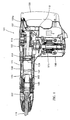
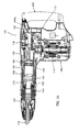
- FIG. 1 shows an entire electric hammer 101 as a representative embodiment of the impact tool according to the present invention.
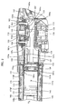
- FIGS. 2 , 4 and 6 are enlarged sectional views each showing an essential part of the hammer.
- FIG. 2 shows the state in which a slide sleeve for forcibly moving a dynamic vibration reducer is substantially in an intermediate position.
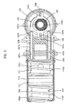
- FIGS. 4 and 5 show the state in which the slide sleeve is in a front end position
- FIGS. 6 and 7 show the state in which the slide sleeve is in a rear end position
- the hammer 101 of this embodiment includes a body 103, a hammer bit 119 detachably coupled to the tip end region (on the left side as viewed in FIG. 1 ) of the body 103 via a tool holder 137, and a handgrip 109 that is connected to the body 103 on the side opposite the hammer bit 119 and designed to be held by a user.
- the body 103 and the hammer bit 119 are features that correspond to the "tool body” and the "tool bit", respectively, according to the present invention.
- the hammer bit 119 is held by the tool holder 137 such that it is allowed to reciprocate with respect to the tool holder 137 in its axial direction and prevented from rotating with respect to the tool holder 137 in its circumferential direction.
- the side ofthe hammer bit 119 is taken as the front side and the side of the handgrip 109 as the rear side.
- the body 103 includes a motor housing 105 that houses a driving motor 111, and a gear housing 107 that houses a first motion converting mechanism 113 and a second motion converting mechanism 116, and a barrel housing 108 that houses a striking mechanism 115.
- the rotating output of the driving motor 111 is appropriately converted into linear motion via the first motion converting mechanism 113 and transmitted to the striking element 115. Then, an impact force is generated in the axial direction of the hammer bit 119 via the striking element 115. Further, the rotating output of the driving motor 111 is transmitted to the second motion converting mechanism 116 via the first motion converting mechanism 113 and converted into linear motion by the second motion converting mechanism 116.
- the linear motion then serves as a driving force for forcibly vibrating a dynamic vibration reducer 171 which will be described below.
- the first motion converting mechanism 113 and the striking mechanism 115 are features that correspond to the "actuating mechanism", and the second motion converting mechanism 116 corresponds to the "mechanical vibration mechanism” according to this invention.
- the driving motor 111 is a feature that corresponds to the "motor” according to this invention. Further, a slide switch 109a is provided on the handgrip 109 and can be slid by the user to drive the driving motor 111.
- the first motion converting mechanism 113 includes a driving gear 121 that is rotated in a horizontal plane by the driving motor 111 (see FIG. 1 ), a first crank shaft 125 integrally having a driven gear 123 that engages with the driving gear 121, a connecting member in the form of a crank arm 127 that is loosely connected at its one end to the first crank shaft 125 via an eccentric pin 126 in a position displaced a predetermined distance from the center of rotation of the first crank shaft 125, and a driving element in the form of a piston 129 mounted to the other end of the crank arm 127 via a connecting shaft 128.
- the first crank shaft 125, the eccentric pin 126, the crank arm 127 and the piston 129 form a first crank mechanism.
- the striking mechanism 115 includes a striking element in the form of a striker 143 that is slidably disposed within the bore of the cylinder 141, and an intermediate element in the form of an impact bolt 145 that is slidably disposed within the tool holder 137 and transmits the kinetic energy of the striker 143 to the hammer bit 119.
- An air chamber 141a is defined between the piston 129 and the striker 143 within the cylinder 141.
- the striker 143 is driven via the action of an air spring of the air chamber 141a ofthe cylinder 141 which is caused by sliding movement of the piston 129.
- the striker 143 then collides with (strikes) the intermediate element in the form of the impact bolt 145 that is slidably disposed within the tool holder 137 and transmits the striking force to the hammer bit 119 via the impact bolt 145.
- the cylinder 141 is disposed coaxially with the hammer bit 119. Therefore, the piston 129 and the striker 143 linearly move on the same axis as the hammer bit 119. Further, the cylinder 141 is inserted from the front into the bore of a cylindrical cylinder holding portion 107a formed in the front region of the gear housing 107 and held there, and is housed within the barrel housing 108 joined to the gear housing 107.
- the dynamic vibration reducer 171 that reduces vibration of the body 103 during hammering operation and the second motion converting mechanism 116 that forcibly vibrates the dynamic vibration reducer 171 by actively driving a weight 173 ofthe dynamic vibration reducer 171 will now be described.
- forcibly vibrating the dynamic vibration reducer 171 is referred to as forced vibration.
- the dynamic vibration reducer 171 is provided in the inner space of the barrel housing 108 and mainly includes a cylindrical weight 173 annularly arranged outside the cylinder 141 and front and rear biasing springs 175F, 175R disposed on the front and rear sides of the weight 173 in the axial direction of the hammer bit.
- the biasing springs 175F, 175R are features that correspond to the "elastic element" according to this invention.
- the front and rear biasing springs 175F, 175R exert a spring force on the weight 173 in a direction toward each other when the weight 173 moves in the axial direction ofthe hammer bit 119.
- the weight 173 is arranged such that its center (of gravity) coincides with the axis ofthe hammer bit 119 and can freely slide with its outer wall surface held in contact with the inner wall surface (cylindrical surface) of the barrel housing 108.
- the front and rear biasing springs 175F, 175R are formed by compression coil springs and, like the weight 173, they are arranged such that each of their centers coincides with the axis ofthe hammer bit 119.
- One end (rear end) of the rear biasing spring 175R is held in contact with a front surface of the flange 151a ofthe slide sleeve 151, while the other end (front end) is held in contact with the axial rear end ofthe weight 173.
- one end (rear end) of the front biasing spring 175F is held in contact with the axial front end of the weight 173, while the other end (front end) is held in contact with a stepped surface 108a ofthe barrel housing 108.
- the slide sleeve 151 forms an input member that inputs the driving force ofthe second motion converting mechanism 116 into the weight 173 via the rear biasing spring 175R.
- the slide sleeve 151 is fitted on the cylinder 141 such that it can slide in the axial direction ofthe hammer bit, and the slide sleeve 151 is slid by the second motion converting mechanism 116.
- the slide sleeve 151 is a feature that corresponds to the "sliding element" according to this invention.
- An air vent 141b is formed in the cylinder 141 in order to regulate pressure of the air chamber 141a and provides communication between the air chamber 141a and the outside.
- the slide sleeve 151 In order to prevent the slide sleeve 151 fitted on the cylinder 141 from always closing the air vent 141b, the slide sleeve 151 includes an annular space 151b that always communicates with the air vent 141b, and a plurality of communication holes 151c that radially extend through the slide sleeve 151 and provide communication between the space 151b and the outside.
- the second motion converting mechanism 116 is disposed above the first motion converting mechanism 113.
- the second motion converting mechanism 116 mainly includes a second crank shaft 153 that is rotationally driven in a horizontal plane by rotation of the eccentric pin 126 of the first motion converting mechanism 113, an eccentric shaft portion I55 integrally formed with the second crank shaft 153, a connecting plate 157 that is caused to reciprocate in the axial direction of the hammer bit by rotation of the eccentric shaft portion 155, and an actuating member in the form of right and left straight rods 159 that linearly move together with the connecting plate 157 and moves the slide sleeve 151 forward.
- the second crank shaft 153, the eccentric shaft portion 155 and the connecting plate 157 form the second crank mechanism which is a feature that corresponds to the "second crank mechanism" according to this invention.
- the second crank shaft 153 is coaxially opposed to the first crank shaft 125.
- the second crank shaft 153 has a disk-like portion 153a on its axial lower end.
- a recess (groove) 153b is formed in the lower surface of the disk-like portion 153a in a position displaced from the center of rotation of the second crank shaft 153.
- the recess 153b is engaged with a protruding end 126a of the eccentric pin 126 of the first motion converting mechanism 113.
- the recess 153b and the protruding end 126a are features that correspond to the "concave portion" and the "convex portion", respectively, according to this invention.
- the second crank shaft 153 is rotationally driven by a driving force that is inputted from the first crank shaft 125 via engagement between the recess 153b and the protruding end 126.
- An opening 107b to be used for mounting the first motion converting mechanism 113 is formed in the gear housing 107 above the first motion converting mechanism 113.
- the second crank mechanism is mounted on a crank cap 163 which is removably fitted over the opening 107b.
- the crank cap 163 is a feature that corresponds to the "covering member" according to this invention.
- the second crank shaft 153 is rotatably supported on the crank cap 163 via a bearing 165.
- the eccentric shaft portion 155 has a circular shape of which center is displaced a predetermined distance from the center of rotation of the second crank shaft 153.
- the connecting plate 157 is engaged with a ring 155a that is fitted on the eccentric shaft portion 155, via an elliptical hole 157a elongated in a direction transverse to the axial direction ofthe hammer bit. Further, the connecting plate 157 is guided by front and rear guide pins 156 mounted to the crank cap 163 in such a manner as to linearly move in the axial direction of the hammer bit.
- front and rear guide grooves 157c are formed in the connecting plate 157 and extend in the axial direction of the hammer bit, and the guide grooves 157c are slidably engaged with the associated guide pins 156.
- the right and left rods 159 are slidably fitted into respective guide holes 107c that are formed through the cylinder holding portion 107a of the gear housing 107 in the axial direction of the hammer bit.
- One axial end (rear end) of each of the rods 159 is held in contact with a planar front surface 157b of the connecting plate 157, while the other axial end (front end) is held in contact with a rear end surface of the slide sleeve 151.
- the second crank shaft 153 and the connecting plate 157 which form the second crank mechanism are mounted to the crank cap 163 before the crank cap 163 is mounted on the opening 107b of the gear housing 107.
- the connecting plate 157 is held between the inner wall surface of the crank cap 163 and the disk-like portion 153a of the second crank shaft 153, so that the connecting plate 157 is prevented from moving in the axial direction of the second crank shaft 153 (in the vertical direction).
- the crank cap 163 with the second crank shaft 153 and the connecting plate 157 mounted thereto is fitted over the opening 107b from outside (above) the gear housing 107 and fastened to the gear housing 107 by a plurality of screws 163a.
- the recess 153b formed in the disk-like portion 153a of the second crank shaft 153 is engaged with the protruding end 126a of the eccentric pin 126 of the first crank mechanism which is already mounted within the gear housing 107, and the rear end of the rod 159 is brought into contact with the front surface 157b of the connecting plate 157.
- the first and second crank mechanisms are assembled in a mechanically interconnected manner such that the rotating force can be transmitted.
- the kinetic energy of the striker 143 which is caused by the collision with the impact bolt 145 is transmitted to the hammer bit 119.
- the hammer bit 119 performs a striking movement in its axial direction, and the hammering operation is performed on the workpiece.
- impulsive and cyclic vibration is caused in the body 103 in the axial direction ofthe hammer bit.
- Main vibration of the body 103 which is to be reduced is a compressing reaction force which is produced when the piston 129 and the striker 143 compress air within the air chamber 141a, and a striking reaction force which is produced with a slight time lag behind the compressing reaction force when the striker 143 strikes the hammer bit 119 via the impact bolt 145.
- the weight 173 and the biasing springs 175F, 175R serve as vibration reducing elements in the dynamic vibration reducer 171 and cooperate to passively reduce vibration of the body 103 of the hammer 101.
- the above-mentioned vibration which is caused in the body 103 of the hammer 101 can be effectively alleviated or reduced.
- a user strongly presses the hammer 101 against the workpiece, so that a considerable load is applied to the hammer bit 119 from the workpiece side. Therefore, although vibration reduction is highly required, the amount of vibration to be inputted to the dynamic vibration reducer 171 may be limited.
- vibration of the body 103 can be more effectively reduced by forced vibration of the dynamic vibration reducer 171.
- the second crank shaft 153 that is engaged with the protruding end 126a of the eccentric pin 126 via the recess 153b is caused to rotate at the same speed as the first crank shaft 125.
- the connecting plate 157 engaged with the eccentric shaft portion 155 is caused to reciprocate in the axial direction of the hammer bit 119.
- FIGS. 2 and 3 show the state in which the slide sleeve 151 that moves in the longitudinal direction is substantially in its intermediate position.
- FIGS. 4 and 5 show the state in which the slide sleeve 151 is in its front end position
- FIGS. 6 and 7 show the state in which the slide sleeve 151 is in its rear end position.
- the weight 173 of the dynamic vibration reducer 171 is actively driven via the biasing springs 175F, 175R and causes the dynamic vibration reducer 171 to be forcibly vibrated.
- the dynamic vibration reducer 171 serves as an active vibration reducing mechanism in which the weight 173 is actively driven. Therefore, the vibration which is caused in the body 103 during hammering operation can be further effectively reduced or alleviated. As a result, a sufficient vibration reducing function can be ensured even in operations of the type in which, although vibration reduction is highly required, only a small amount of vibration is inputted to the dynamic vibration reducer 171 and the dynamic vibration reducer 171 does not sufficiently function, particularly, for example, in a hammering operation which is performed with the user's strong pressing force applied to the body 103 (force of pressing the hammer bit 119 against the workpiece).
- a spring receiving member in the form of the slide sleeve 151 is driven via the second crank mechanism which is formed by the eccentric shaft portion 155 and the connecting plate 157, and the weight 173 is actively driven via the rear biasing spring 175R.
- the timing of driving the weight 173 with respect to the timing of driving the piston 129 (the striker 143) by the first crank mechanism, or the crank phase ofthe second crank mechanism can be adjusted such that, when the striker 143 is caused to move forward via pressure fluctuations of the air chamber 141a and strikes the hammer bit 119 via the impact bolt 145, the weight 173 of the dynamic vibration reducer 171 counteracts impulsive vibration caused in the body 103 or linearly moves in a direction opposite to the intermediate region of either one or both of the above-mentioned compressing reaction force and the striking reaction force produced immediately after the compressing reaction force.
- the linear movement ofthe weight 173 can be timed to coincide with generation of a large amount of vibration during hammering operation, so that the vibration reducing function of the weight 173 can be performed in an optimum manner.
- the weight 173 and the biasing springs 175F, 175R which form the dynamic vibration reducer 171 are annularly arranged outside the cylinder 141.
- the space between the outer periphery of the cylinder 141 and the inner periphery of the barrel housing 108 can be effectively utilized to dispose the vibration reducing mechanism, which is effective in reducing the size of the electric hammer 101.
- the weight 173 and the biasing springs 175F, 175R can be disposed such that their centers of gravity are placed on the axis of the hammer bit 119.
- a couple force of lateral or vertical rotation around an axis extending transverse to the axial direction of the hammer bit
- a couple can be prevented from acting upon the body 103 when the weight 173 reciprocates in the axial direction ofthe hammer bit 119.
- the weight 173 is disposed such that it can slide in the axial direction of the hammer bit 119 along the inner wall surface ofthe barrel housing 108. With this construction, the sliding movement of the weight 173 can be stabilized. Further, the weight 173 can be disposed out of contact with the outer wall surface ofthe cylinder 141. Thus, the weight 173 can be avoided from having an adverse effect on the air vent 141b which is formed in the cylinder 141 in order to provide communication between the air chamber 141a and the outside.
- the crank cap 163 is fitted over the opening 107b in order to close the opening 107b ofthe gear housing 107, and the second crank shaft 153 and the connecting plate 157 which form the second crank mechanism are mounted on the crank cap 163. Moreover, when the crank cap 163 is fitted over the opening 107b, the recess 153b formed in the disk-like portion 153a of the second crank shaft 153 is engaged with the protruding end 126a of the eccentric pin 126 of the first crank shaft 125, so that the second crank mechanism is mechanically interconnected with the first crank mechanism. With this construction, the second crank mechanism can be mounted simply by mounting the crank cap 163 on the opening 107b. Thus, according to this embodiment, mounting of the second crank mechanism is facilitated and ease of assembly can be increased.
- crank cap 163 in which the second crank shaft 153 and the connecting plate 157 which form the second crank mechanism are mounted on the crank cap 163, a crank cap which is designed and provided exclusively for the purpose of closing the opening 107b, or a crank cap without the second crank mechanism, can be mounted in place of the crank cap 163 with the second crank mechanism. In this manner, shift from the hammer 101 with the dynamic vibration reducer 171 to a low-end model without the dynamic vibration reducer 171 can be readily realized.
- the opening 107b formed in the gear housing 107 is designed and provided as a hole through which the first crank mechanism is mounted in the gear housing 107. Further, an upper region above the first crank mechanism exists as free space. In this embodiment, the second crank mechanism is disposed by utilizing this free space, so that the second crank mechanism can be installed without changing the outside dimensions of the existing electric hammer 101.
- the slide sleeve 151 that is slidably fitted on the cylinder 141 has a cylindrical body elongated in the axial direction of the hammer bit or in the sliding direction. With this construction, the sliding movement of the slide sleeve 151 can be stabilized. As a result, a simple construction in which the rods 159 push the slide sleeve 151 can be applied.
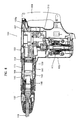
- FIG. 8 is a sectional view showing an entire electric hammer 101 according to this embodiment.
- FIG. 9 is an enlarged sectional view showing an essential part ofthe hammer.
- FIG. 10 is a sectional view taken along line D-D in FIG. 9 .
- This embodiment is a modification to the mechanical vibration mechanism for forcibly vibrating the dynamic vibration reducer 171 in the electric hammer 101 having the dynamic vibration reducer 171 that reduces vibration ofthe body 103.
- forced vibration ofthe dynamic vibration reducer 171 is effected by the second crank mechanism which is mounted on a motion converting mechanism 213 that drives the striker 143, and the second motion converting mechanism 116 in the above-mentioned first embodiment is omitted.
- the second crank mechanism which is mounted on a motion converting mechanism 213 that drives the striker 143
- the second motion converting mechanism 116 in the above-mentioned first embodiment is omitted.
- it has the same construction as the first embodiment.
- Components or elements in this embodiment which are substantially identical to those in the first embodiment are given like numerals as in the first embodiment and will not be described or only briefly described.
- the motion converting mechanism 213 includes the first crank mechanism that drives the striker 143 and the second crank mechanism that drives the dynamic vibration reducer 171.
- the first crank mechanism mainly includes a driving gear 221 that is rotated in a horizontal plane by the driving motor 111 (see FIG.
- a driven gear 223 that engages with the driving gear 221
- a crank shaft 225 that rotates together with the driven gear 223
- a crank plate 225a that is integrally formed on the upper end of the crank shaft 225
- a connecting member in the form of a crank arm 227 that is loosely connected at its one end to the crank plate 225a via an eccentric pin 226 in a position displaced a predetermined distance from the center of rotation of the crank plate 225a
- a driving element in the form of a piston 229 mounted to the other end of the crank arm 227 via a connecting shaft 228.
- the second crank mechanism mainly includes an eccentric shaft portion 255 integrally formed with the crank shaft 225, a connecting plate 257 that is caused to reciprocate in the axial direction of the hammer bit 119 by rotation of the eccentric shaft portion 255, and an actuating member in the form of right and left straight rods 259 that linearly move together with the connecting plate 257 and move the slide sleeve 151 forward.
- the eccentric shaft portion 255 has a circular shape of which center is displaced a predetermined distance from the center of rotation of the crank shaft 225.
- the connecting plate 257 is engaged with a ring 255a that is fitted on the eccentric shaft portion 255, via an elliptical hole 257a elongated in a direction transverse to the axial direction of the hammer bit. Further, the connecting plate 257 is guided by front and rear guide pins 256 mounted to the gear housing 107 in such a manner as to linearly move. Further, front and rear guide grooves 257c are formed in the connecting plate 257 and extend in the axial direction of the hammer bit, and the guide grooves 257c are slidably engaged with the associated guide pins 256. As shown in FIG.
- the right and left rods 259 are slidably fitted into respective guide holes 107c that are formed through the cylinder holding portion 107a of the gear housing 107 in the axial direction of the hammer bit.
- One axial end (rear end) of each of the rods 259 is held in contact with a planar front surface 257b ofthe connecting plate 257, while the other axial end (front end) is held in contact with a rear end surface of the slide sleeve 151 of the dynamic vibration reducer 171.
- the opening 107b is formed in the gear housing 107 above the motion converting mechanism 213 and covered by a crank cap 263 which is removably fastened to the gear housing 107 by screws 263a.
- the weight 173 is actively driven via the biasing springs 175F, 175R by linearly moving the slide sleeve 151 via the second crank mechanism.
- vibration which is caused in the body 103 in the axial direction of the hammer bit during hammering operation can be effectively reduced or alleviated by forced vibration of the dynamic vibration reducer 171.
- the second crank mechanism that forcibly vibrates the dynamic vibration reducer 171 is mounted on the first crank mechanism that drives the striker 143.
- the eccentric shaft portion 255 is disposed on the crank shaft 225, and the slide sleeve 151 is driven via the connecting plate 257 that engages with the eccentric shaft portion 255 and via the rods 259.
- the number of parts for driving the slide sleeve 151 can be reduced compared with the first embodiment.
- the electric hammer 101 is described as a representative example of the impact tool.
- the present invention can also be applied to a hammer drill in which the hammer bit 119 can perform a striking movement in its axial direction and a rotation around its axis.
- FIG. 11 shows an entire electric hammer 101 as a representative embodiment of the impact tool according to the present invention.
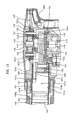
- FIGS. 12 and 13 are enlarged sectional views each showing an essential part ofthe hammer, in the open state and the closed state of an air vent of an air chamber, respectively.
- FIG. 14 is a sectional view taken along line A-A in FIG. 12 .
- the hammer 101 of this embodiment includes a body 103, a hammer bit 119 detachably coupled to the tip end region (on the left side as viewed in FIG. 11 ) of the body 103 via a tool holder 137, and a handgrip 109 that is connected to the body 103 on the side opposite the hammer bit 119 and designed to be held by a user.
- the body 103 and the hammer bit 119 are features that correspond to the "tool body” and the "tool bit", respectively, according to the present invention.
- the hammer bit 119 is held by the tool holder 137 such that it is allowed to reciprocate with respect to the tool holder 137 in its axial direction and prevented from rotating with respect to the tool holder 137 in its circumferential direction.
- the side ofthe hammer bit 119 is taken as the front side and the side of the handgrip 109 as the rear side.
- the body 103 includes a motor housing 105 that houses a driving motor 111, and a gear housing 107 that houses a first motion converting mechanism 113 and a second motion converting mechanism 116, and a barrel housing 108 that houses a striking mechanism 115.
- the rotating output of the driving motor 111 is appropriately converted into linear motion via the first motion converting mechanism 113 and transmitted to the striking element 115. Then, an impact force is generated in the axial direction of the hammer bit 119 via the striking element 115. Further, the rotating output of the driving motor 111 is transmitted to the second motion converting mechanism 116 via the first motion converting mechanism 113 and converted into linear motion by the second motion converting mechanism 116.
- the linear motion is inputted into a slide sleeve 151 that opens and closes an air vent 141b of an air chamber 141a which will be described below, as a driving force for sliding the slide sleeve 151.
- the driving motor 111 is a feature that corresponds to the "motor” according to this invention.
- a slide switch 109a is provided on the handgrip 109 and can be slid by the user to drive the driving motor 111.
- the first motion converting mechanism 113 includes a driving gear 121 that is rotated in a horizontal plane by the driving motor 111 (see FIG. 11 ), a first crank shaft 125 integrally having a driven gear 123 that engages with the driving gear 121, a connecting member in the form of a crank arm 127 that is loosely connected at its one end to the first crank shaft 125 via an eccentric pin 126 in a position displaced a predetermined distance from the center of rotation of the first crank shaft 125, and a driving element in the form of a piston 129 mounted to the other end of the crank arm 127 via a connecting shaft 128.
- the first crank shaft 125, the eccentric pin 126, the crank arm 127 and the piston 129 form a first crank mechanism.
- the striking mechanism 115 includes a striking element in the form of a striker 143 that is slidably disposed within the bore of the cylinder 141, and an intermediate element in the form of an impact bolt 145 that is slidably disposed within the tool holder 137 and transmits the kinetic energy of the striker 143 to the hammer bit 119.
- An air chamber 141a is defined between the piston 129 and the striker 143 within the cylinder 141.
- the striker 143 is driven via the action of an air spring of the air chamber 141a of the cylinder 141 which is caused by sliding movement of the piston 129.
- the striker 143 then collides with (strikes) the intermediate element in the form of the impact bolt 145 that is slidably disposed within the tool holder 137 and transmits the striking force to the hammer bit 119 via the impact bolt 145.
- the cylinder 141 is disposed coaxially with the hammer bit 119. Therefore, the piston 129 and the striker 143 linearly move on the same axis as the hammer bit 119. Further, the cylinder 141 is inserted from the front into the bore of a cylindrical cylinder holding portion 107a formed in the front region of the gear housing 107 and held there, and is housed within the barrel housing 108 joined to the gear housing 107.
- the air chamber 141a serves to drive the striker 143 via the action of the air spring and communicates with the outside via one or more pressure regulating air vents 141b that are formed in the cylinder 141 and radially extend through it.
- the air vent 141b is a feature that corresponds to the "ventilation part” according to this invention.
- a slide sleeve 151 is disposed outside the cylinder 141 and serves to open and close the air vent 141b.
- the slide sleeve 151 is a feature that corresponds to the "ventilation part opening-closing member" according to this invention.
- the slide sleeve 151 is fitted on the cylinder 141 such that it can slide in the axial direction of the hammer bit, and the slide sleeve 151 is slid by the second motion converting mechanism 116.
- the slide sleeve 151 has a ring-like groove 151b and a plurality of communication holes 151c.
- the ring-like groove 151b is formed in the inner wall surface of the slide sleeve 151, having a predetermined width in the axial direction and extending in the circumferential direction of the slide sleeve 151.
- the communication holes 151c radially extend through the slide sleeve 151 in such a manner as to provide communication between the groove 151b and the outside.
- the slide sleeve 151 slides on the cylinder 141 and is placed in a region in which the ring-like groove 151b faces the air vent 141b of the cylinder 141, the slide sleeve 151 opens the air vent 141b.
- the slide sleeve 151 moves out of the region in which the ring-like groove 151b faces the air vent 141b, the slide sleeve 151 closes the air vent 141b.
- the second motion converting mechanism 116 is disposed above the first motion converting mechanism 113.
- the second motion converting mechanism 116 mainly includes a second crank shaft 153 that is rotationally driven in a horizontal plane by rotation of the eccentric pin 126 of the first motion converting mechanism 113, an eccentric shaft portion 155 integrally formed with the second crank shaft 153, a connecting member in the form of a connecting plate 157 that is caused to reciprocate in the axial direction of the hammer bit by rotation of the eccentric shaft portion 155, an actuating member in the form of right and left straight rods 159 that linearly move together with the connecting plate 157 and move the slide sleeve 151 forward, and a pressing spring 161 that biases the slide sleeve 151 in such a manner as to move the slide sleeve 151 rearward.
- the second crank shaft 153, the eccentric shaft portion 155 and the connecting plate 157 form the second crank mechanism which is a feature that corresponds to the "second crank mechanism
- the second crank shaft 153 is coaxially opposed to the first crank shaft 125.
- the second crank shaft 153 has a disk-like portion 153a on its axial lower end.
- a recess (groove) 153b is formed in the lower surface of the disk-like portion 153a in a position displaced from the center of rotation of the second crank shaft 153.
- the recess 153b is engaged with a protruding end 126a of the eccentric pin 126 of the first motion converting mechanism 113.
- the recess 153b and the protruding end 126a are features that correspond to the "concave portion" and the "convex portion", respectively, according to this invention.
- the second crank shaft 153 is rotationally driven by a driving force that is inputted from the first crank shaft 125 via engagement between the recess 153b and the protruding end 126.
- An opening 107b to be used for mounting the first motion converting mechanism 113 is formed in the gear housing 107 above the first motion converting mechanism 113.
- the second crank mechanism is mounted on a crank cap 163 which is removably fitted over the opening 107b.
- the crank cap 163 is a feature that corresponds to the "covering member" according to this invention.
- the second crank shaft 153 is rotatably supported on the crank cap 163 via a bearing 165.
- the eccentric shaft portion 155 has a circular shape of which center is displaced a predetermined distance from the center of rotation of the second crank shaft 153.
- the connecting plate 157 is engaged with a ring 155a that is fitted on the eccentric shaft portion 155, via an elliptical hole 157a elongated in a direction transverse to the axial direction ofthe hammer bit. Further, the connecting plate 157 is guided by front and rear guide pins 156 mounted to the crank cap 163 in such a manner as to linearly move in the axial direction ofthe hammer bit.
- front and rear guide grooves 157c are formed in the connecting plate 157 and extend in the axial direction of the hammer bit, and the guide grooves 157c are slidably engaged with the associated guide pins 156.
- the right and left rods 159 are slidably fitted into respective guide holes 107c that are formed through the cylinder holding portion 107a of the gear housing 107 in the axial direction of the hammer bit.
- One axial end (rear end) of each of the rods 159 is held in contact with a planar front surface 157b ofthe connecting plate 157, while the other axial end (front end) is held in contact with a rear end surface of the slide sleeve 151.
- the pressing spring 161 is a coil spring disposed outside the slide sleeve 151.
- One axial end (rear end) ofthe pressing spring 161 is held in contact with a flange 151a of the slide sleeve 151, while the other axial end (front end) is held in contact with a stepped surface 108a ofthe barrel housing 108.
- the second crank shaft 153 and the connecting plate 157 which form the second crank mechanism are mounted to the crank cap 163 before the crank cap 163 is mounted on the opening 107b ofthe gear housing 107.
- the connecting plate I57 is held between the inner wall surface of the crank cap 163 and the disk-like portion 153a of the second crank shaft 153, so that the connecting plate 157 is prevented from moving in the axial direction ofthe second crank shaft 153.
- the crank cap 163 with the second crank shaft 153 and the connecting plate 157 mounted thereto is fitted over the opening 107b from outside (above) the gear housing 107 and fastened to the gear housing 107 by a plurality of screws 163a.
- the recess 153b formed in the disk-like portion 153a of the second crank shaft 153 is engaged with the protruding end 126a of the eccentric pin 126 of the first crank mechanism which is already mounted within the gear housing 107, and the rear end of the rod 159 is brought into contact with the front surface 157b of the connecting plate 157.
- the first and second crank mechanisms are assembled in a mechanically interconnected manner such that the rotating force can be transmitted.
- the kinetic energy of the striker 143 which is caused by the collision with the impact boh 145 is transmitted to the hammer bit 119.
- the hammer bit 119 performs a striking movement in its axial direction, and the hammering operation is performed on the workpiece.
- the slide sleeve 151 controls opening and closing of the air vent 141b of the cylinder 141 via the second motion converting mechanism 116.
- the eccentric shaft portion 155 of the second crank shaft 153 is caused to rotate in a horizontal plane.
- the connecting plate 157 engaged with the eccentric shaft portion 155 is caused to reciprocate in the axial direction of the hammer bit 119.
- the maximum retracted end or the rearmost position to which the piston 129 can be moved is defined as the top dead center, while the maximum advanced end or the front position to which the piston 129 can be moved is defined as the bottom dead center.
- the crank angle of the first crank mechanism is 0°, the piston 129 is placed in the top dead center, while, when the crank angle is 180°, the piston 129 is placed in the bottom dead center.
- the opening and closing timing of the slide sleeve 151 is set such that, when the crank angle is in the range of about 135° to 220°, the air vent 141b of the air chamber 141a is opened, while, otherwise or when the crank angle is in the range of about 0° to 135° or 220° to 360°, the air vent 141b is closed.
- FIG. 12 shows the state in which the air vent 141b is open and
- FIG. 13 shows the state in which the air vent 141b is closed.
- the air chamber 141a has a minimum capacity when the piston 129 is moved a crank angle of about 70° to 87° from the top dead center. Specifically, the piston 129 is placed closest to the striker 143 so that air within the air chamber 141a is compressed to a maximum extent. Thereafter, the striker 143 is caused to move forward by pressure ofthe high-pressure compressed air. When the crank angle is about 180°, the striker 143 strikes the hammer bit 119 via the impact bolt 145. After the striking movement, the striker 143 is caused to move rearward by rebound of the striking movement and by pressure difference (suction force) between the pressure within the air chamber 141a which acts upon the rear end surface of the striker 143 and the outside pressure (substantially the atmospheric pressure).
- the period between the instant when the striker 143 starts moving forward and the instant when the striker 143 returns to the initial position after colliding with the hammer bit 119 is defined as one cycle.
- the slide sleeve 151 starts opening the air vent 141b at the crank angle of about 137° and then holds the open state in a predetermined angle range. Thereafter, the slide sleeve 151 closes the air vent 141b at the crank angle of about 220°.
- the times when the slide sleeve 151 opens and closes the air vent 141b can be arbitrarily set in the relationship with the position of the striker 143 (the piston 129).
- such times can be set such that, during forward movement (striking movement) of the striker 143, the air vent 141b is opened in the position where (at the time when) high-pressure pressurized air within the air chamber 141a can provide optimum striking speed for the striker 143. Further, during rearward movement of the striker 143, the air vent 141b is closed in the position where (at the time when) the striker 143 can be acted upon by optimum suction force. As a result, performance of the electric hammer 101 can be improved. Further, the period (interval) during which the air vent 141b is open is determined by the width (in the axial direction of the hammer bit 119) of the ring-like groove 151b formed in the slide sleeve 151.
- the times when the slide sleeve 151 opens and closes the air vent 141b can be easily adjusted by appropriately adjusting (setting) the position of the eccentric shaft portion 155 ofthe second crank mechanism in the direction of rotation with respect to the eccentric pin 126 of the first crank mechanism which drives the striker 143.
- the period during which the air vent 141b is open can be appropriately adjusted by changing the width of the ring-like groove 151b formed in the slide sleeve 151.
- the air vent 141b can be opened only when necessary and only during a necessary period.
- the crank cap 163 is fitted over the opening 107b in order to close the opening 107b ofthe gear housing 107, and the second crank shaft 153 and the connecting plate 157 which form the second crank mechanism are mounted on the crank cap 163. Moreover, when the crank cap 163 is fitted over the opening 107b, the recess 153b formed in the disk-like portion 153a of the second crank shaft 153 is engaged with the protruding end 126a of the eccentric pin 126 of the first crank shaft 125, so that the second crank mechanism is mechanically interconnected with the first crank mechanism. With this construction, the second crank mechanism can be mounted simply by mounting the crank cap 163 on the opening 107b. Thus, according to this embodiment, mounting of the second crank mechanism is facilitated and ease of assembly can be increased.
- the opening 107b formed in the gear housing 107 is designed and provided as a hole through which the first crank mechanism is mounted in the gear housing 107. Further, an upper region above the first crank mechanism exists as free space. In this embodiment, the second crank mechanism is disposed by utilizing this free space, so that the second crank mechanism can be installed without changing the outside dimensions of the existing electric hammer 101.
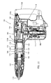
- FIG. 15 shows an entire electric hammer 101 according to this embodiment.
- FIG. 16 is an enlarged sectional view showing an essential part of the hammer.
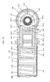
- FIG. 17 is a sectional view taken along line B-B in FIG. 16 .
- a dynamic vibration reducer 171 for reducing vibration of the body 103 is installed in the hammer 101.
- the slide sleeve 151 that linearly moves in the axial direction of the hammer bit in order to open and close the air vent 141b of the air chamber 141a is utilized as a vibration means for actively vibrating the dynamic vibration reducer 171.
- it has the same construction as the first embodiment.
- Components or elements in this embodiment which are substantially identical to those in the first embodiment are given like numerals as in the first embodiment and will not be described or only briefly described.
- forcibly vibrating the dynamic vibration reducer 171 is referred to as forced vibration.
- the dynamic vibration reducer 171 is provided in the inner space of the barrel housing 108 and mainly includes a cylindrical weight 173 annularly arranged outside the cylinder 141 and front and rear biasing springs 175F, 175R disposed on the front and rear sides of the weight 173 in the axial direction of the hammer bit.
- the front and rear biasing springs 175F, 175R exert a spring force on the weight 173 in a direction toward each other when the weight 173 moves in the axial direction ofthe hammer bit 119.
- the weight 173 is arranged such that its center (of gravity) coincides with the axis ofthe hammer bit 119 and can freely slide with its outer wall surface held in contact with the inner wall surface of the barrel housing 108.
- the front and rear biasing springs 175F, 175R are formed by compression coil springs and, like the weight 173, they are arranged such that each of their centers coincides with the axis ofthe hammer bit 119.
- One end (rear end) of the rear biasing spring 175R is held in contact with a front surface of the flange 151a of the slide sleeve 151, while the other end (front end) is held in contact with the axial rear end of the weight 173.
- the rear biasing spring 175R also serves as a pressing spring for biasing the slide sleeve 151 rearward.
- the dynamic vibration reducer 171 having the above-described construction serves to reduce impulsive and cyclic vibration caused during hammering operation (when the hammer bit 119 is driven).
- the weight 173 and the biasing springs 175F, 175R serve as vibration reducing elements in the dynamic vibration reducer 171 and cooperate to passively reduce vibration of the body 103 of the hammer 101.
- the vibration of the body 103 in the hammer 101 can be effectively alleviated or reduced.
- the connecting plate 157 engaged with the eccentric shaft portion 155 is caused to reciprocate in the axial direction of the hammer bit 119.
- the connecting plate 157 moves forward, the slide sleeve 151 is pushed forward via the rod 159 and compresses the biasing springs 175F, 175R.
- the connecting plate 157 moves rearward, the slide sleeve 151 is pushed rearward by the spring force of the biasing springs 175F, 175R.
- the weight 173 of the dynamic vibration reducer 171 is actively driven via the biasing springs 175F, 175R and causes the dynamic vibration reducer 171 to be forcibly vibrated.
- the slide sleeve 151 serves as a vibration means for forcibly vibrating the dynamic vibration reducer 171 by actively driving the weight 173 of the dynamic vibration reducer 171.
- the dynamic vibration reducer 171 serves as an active vibration reducing mechanism in which the weight 173 is actively driven. Therefore, the vibration which is caused in the body 103 during hammering operation can be further effectively reduced or alleviated.
- the slide sleeve 151 can provide forced vibration of the dynamic vibration reducer 171 while maintaining the function of controlling opening and closing ofthe air vents 141b which is described in the first embodiment.
- the weight 173 and the biasing springs 175F, 175R which form the dynamic vibration reducer 171 are annularly arranged outside the cylinder 141.
- the outer peripheral space of the cylinder 141 can be effectively utilized.
- the weight 173 and the biasing springs 175F, 175R can be disposed such that their centers of gravity are placed on the axis ofthe hammer bit 119.
- a couple force of lateral or vertical rotation around an axis extending transverse to the axial direction of the hammer bit
- the weight 173 is disposed such that it can slide in the axial direction of the hammer bit along the inner wall surface of the barrel housing 108. With this construction, the sliding movement ofthe weight 173 can be stabilized.
- the electric hammer 101 is described as a representative example of the impact tool.
- the present invention can also be applied to a hammer drill in which the hammer bit 119 can perform a striking movement in its axial direction and a rotation around its axis.
Landscapes
- Engineering & Computer Science (AREA)
- Mechanical Engineering (AREA)
- Percussive Tools And Related Accessories (AREA)
Abstract
Description
- The present invention relates to a vibration reducing technique in an impact tool which drives a tool bit, such as a hammer and a hammer drill.
-
WO2005/105386 discloses an electric hammer having a vibration reducing mechanism. The known hammer has a dynamic vibration reducer, wherein a crank mechanism is utilized to actively drive a weight of the dynamic vibration reducer to reduce vibration caused during hammering operation. - It is an object of the invention to provide a technique for further improving the vibration reducing performance in an impact tool.
- Above-mentioned object can be achieved by a claimed invention. A representative impact tool performs a predetermined hammering operation on a workpiece by a striking movement of a tool bit in its axial direction. The representative impact tool includes a tool body, a cylinder housed within the tool body, a dynamic vibration reducer and a mechanical vibration mechanism. The "predetermined hammering operation" in this invention suitably includes not only a hammering operation in which the tool bit performs only a striking movement in its axial direction, but a hammer drill operation in which it performs a striking movement in its axial direction and a rotation around its axis. The dynamic vibration reducer in this invention has a weight that can linearly move under a biasing force of an elastic element, and the dynamic vibration reducer reduces vibration of the tool body during hammering operation by the movement of the weight in the axial direction of the tool bit. It is at least necessary for the weight as an element of the dynamic vibration reducer to be acted upon by the biasing force of the elastic element. The weight may further be acted upon by a damping force of a damping element. The "elastic element" in this invention typically comprises a spring. The mechanical vibration mechanism actively drives the weight by applying external force other than vibration of the tool body to the weight via the elastic element. By thus actively driving the weight via the mechanical vibration mechanism and forcibly vibrating the dynamic vibration reducer, the dynamic vibration reducer can be steadily actuated regardless ofthe magnitude of vibration on the impact tool.
- According to the preferred embodiment of the present invention, the weight and the elastic element are disposed on the axis ofthe tool bit and between an inner wall surface of the tool body and an outer wall surface of the cylinder in such a manner as to cover at least part of the outer wall surface of the cylinder in the circumferential direction. The manner of "covering at least part ofthe outer wall surface ofthe cylinder in the circumferential direction" widely includes, as for the weight, the manner in which the weight has a cylindrical body which is circular, elliptical or polygonal in section and covers the entire outer wall surface ofthe cylinder in the circumferential direction, and the manner in which the weight has a cylindrical body which has a cut in part in the circumferential direction, such as a body generally C-shaped in section, and as for the elastic element, it represents the manner in which a coil spring is annularly disposed outside the cylinder.
- According to this invention, with the construction in which the weight and the elastic element that form the dynamic vibration reducer are disposed between the inner wall surface of the tool body and the outer wall surface of the cylinder, the centers of gravity ofthe weight and the elastic element can be placed substantially on the axis ofthe tool bit. As a result, a couple, or force of rotation around an axis extending transverse to the axial direction of the tool bit, can be prevented from being generated when the weight moves in the axial direction of the tool bit. Moreover, according to this invention, the existing space can be utilized to dispose the vibration reducing mechanism, which is effective in reducing the size ofthe impact tool.
- According to a further embodiment of the present invention, the impact tool further includes an actuating mechanism that linearly drives the tool bit. The actuating mechanism includes a motor, a striking element that linearly moves in the axial direction ofthe tool bit in such a manner as to cause the tool bit to linearly move, and a first crank mechanism that converts a rotating output of the motor into linear motion and thereby drives the striking element. The mechanical vibration mechanism includes a sliding element that linearly moves in the axial direction ofthe tool bit in such a manner as to apply an external force to the elastic element and a second crank mechanism that converts rotation of the first crank mechanism into linear motion and thereby drives the sliding element. Further, the second crank mechanism is rotationally driven by the motor via the first crank mechanism.
According to this invention, both the striking element and the sliding element can be driven by the single motor, and thus a rational driving system can be provided. - According to a further embodiment of the present invention, the impact tool further includes an opening that is formed in the tool body and provided as a hole through which the first crank mechanism is mounted within the tool body, and a covering member that can be mounted on the opening from outside the tool body in such a manner as to close the opening. The first crank mechanism has a crank shaft that is rotatably disposed within the tool body and faces the opening. The second crank mechanism has a crank shaft that is rotatably mounted to the covering member and opposed to the crank shaft of the first crank mechanism. A concave portion is formed in one of opposed ends of the crank shafts of the first and second crank mechanisms, and a convex portion is formed on the other of the opposed ends of the crank shafts and can engage with the concave portion. When the covering member is mounted on the opening, the crank shaft of the first crank mechanism and the crank shaft of the second crank mechanism are interconnected by engagement between the concave portion and the convex portion such that rotation of the crank shaft of the first crank mechanism can be transmitted to the crank shaft of the second crank mechanism. The manner of being "opposed" in this invention preferably represents the manner of being opposed substantially on the same axis.
- According to this invention, the second crank mechanism is mounted on the covering member for closing the opening, and when the covering member is mounted on the opening, the crank shaft of the first crank mechanism and the crank shaft of the second crank mechanism are interconnected by engagement between the concave portion and the convex portion such that rotation can be transmitted. With this construction, by mounting the second crank mechanism on the covering member in advance and then fitting the covering member over the opening, the second crank mechanism can be easily mounted on the first crank mechanism. Thus, ease of assembly can be increased. The opening formed in the tool body is designed and provided as a hole through which the first crank mechanism is mounted within the tool body. Further, an upper region above the first crank mechanism exists as free space. According to this invention, the second crank mechanism can be disposed by utilizing this free space. Thus, the second crank mechanism can be installed without changing the outside dimensions ofthe existing impact tool.
- According to a further embodiment of the present invention, the weight is disposed on the tool body such that the weight can move along the inner wall surface of the tool body in the axial direction of the tool bit. With this construction, the linear movement of the weight along the inner wall surface of the tool body can be stabilized. Further, the weight and the elastic element which are disposed on the tool body side can be arranged out of contact with the outer wall surface of the cylinder. Therefore, if such a construction is applied to an impact tool of the type, for example, in which the striking element is driven via pressure fluctuations of air within the cylinder and strikes the tool bit, the weight can be avoided from having an adverse effect on the air vent which is formed in the cylinder in order to provide communication between the air chamber and the outside.
- Further, as another aspect of the invention, a representative impact tool may include a tool body, a cylinder housed within the tool body, a driving element that linearly moves in the axial direction ofthe tool bit within the cylinder, a striking element that linearly moves in the axial direction of the tool bit within the cylinder, and an air chamber defined between the driving element and the striking element within the cylinder. The striking element is caused to linearly move via pressure fluctuations ofthe air chamber as a result ofthe linear movement ofthe driving element and strikes the tool bit, whereby the predetermined hammering operation is performed on the workpiece.
- Further, the impact tool may further include a ventilation part that is formed in the cylinder and provides communication between the air chamber and the outside in order to regulate pressure of the air chamber so as to achieve smooth movement of the striking element, and a ventilation part opening-closing member that is disposed outside the cylinder and can slide in the axial direction of the tool bit. During hammering operation by the tool bit, the ventilation part opening-closing member controls opening and closing ofthe ventilation part by moving between an open position for opening the ventilation part and a closed position for closing the ventilation part at a predetermined timing.
- According to the invention, with the construction in which the ventilation part opening-closing member is disposed outside the cylinder and controls opening and closing of the ventilation part, the timing of opening and closing the ventilation part, or the time at which the ventilation part is switched from the closed position to the open position during striking movement of the striking element and the time at which the ventilation part is switched from the open position to the closed position during suction of the striking element, can be arbitrarily adjusted in the relationship with the position ofthe striking element. Specifically, according to this invention, the ventilation part can be opened only when necessary. As a result, the pressure of the air chamber can be controlled such that, during striking movement of the striking element, optimum striking speed is provided for the striking element, and during suction of the striking element, optimum suction force acts upon the striking element.
- Other objects, features and advantages of the present invention will be readily understood after reading the following detailed description together with the accompanying drawings and the claims.
-
-
FIG. 1 is a sectional side view schematically showing an entire electric hammer according to a first embodiment ofthis invention. -
FIG. 2 is an enlarged sectional view showing an essential part of the hammer in the state in which a slide sleeve is substantially in an intermediate position. -
FIG. 3 is a sectional view taken along line A-A inFIG. 2 . -
FIG. 4 is an enlarged sectional view showing the essential part ofthe hammer in the state in which the slide sleeve is in a front end position. -
FIG. 5 is a sectional view taken along line B-B inFIG. 4 . -
FIG. 6 is an enlarged sectional view showing the essential part ofthe hammer in the state in which the slide sleeve is in a rear end position. -
FIG. 7 is a sectional view taken along line C-C inFIG. 6 . -
FIG. 8 is a sectional side view schematically showing an entire electric hammer according to a second embodiment of this invention. -
FIG. 9 is an enlarged sectional view showing an essential part of the hammer. -
FIG. 10 is a sectional view taken along line D-D inFIG. 9 . -
FIG. 11 is a sectional side view schematically showing an entire electric hammer according to a third embodiment of this invention. -
FIG. 12 is an enlarged sectional view showing an essential part of the hammer in the state in which an air vent of an air chamber is open. -
FIG. 13 is an enlarged sectional view showing an essential part of the hammer in the state in which the air vent of the air chamber is closed. -
FIG. 14 is a sectional view taken along line A-A inFIG. 12 . -
FIG. 15 is a sectional side view schematically showing an entire electric hammer according to a fourth embodiment of this invention. -
FIG. 16 is an enlarged sectional view showing an essential part of the hammer. -
FIG. 17 is a sectional view taken along line B-B inFIG. 16 . - Each of the additional features and method steps disclosed above and below may be utilized separately or in conjunction with other features and method steps to provide and manufacture improved impact tools and method for using such impact tools and devices utilized therein. Representative examples ofthe present invention, which examples utilized many of these additional features and method steps in conjunction, will now be described in detail with reference to the drawings. This detailed description is merely intended to teach a person skilled in the art further details for practicing preferred aspects ofthe present teachings and is not intended to limit the scope of the invention. Only the claims define the scope ofthe claimed invention. Therefore, combinations of features and steps disclosed within the following detailed description may not be necessary to practice the invention in the broadest sense, and are instead taught merely to particularly describe some representative examples of the invention, which detailed description will now be given with reference to the accompanying drawings.
- A first embodiment of the present invention is now described with reference to FIGS. to 7.
FIG. 1 shows an entireelectric hammer 101 as a representative embodiment of the impact tool according to the present invention.FIGS. 2 ,4 and6 are enlarged sectional views each showing an essential part of the hammer.FIG. 2 shows the state in which a slide sleeve for forcibly moving a dynamic vibration reducer is substantially in an intermediate position.FIGS. 4 and5 show the state in which the slide sleeve is in a front end position, andFIGS. 6 and7 show the state in which the slide sleeve is in a rear end position - As shown in
FIG. 1 , thehammer 101 of this embodiment includes abody 103, ahammer bit 119 detachably coupled to the tip end region (on the left side as viewed inFIG. 1 ) of thebody 103 via atool holder 137, and ahandgrip 109 that is connected to thebody 103 on the side opposite thehammer bit 119 and designed to be held by a user. Thebody 103 and thehammer bit 119 are features that correspond to the "tool body" and the "tool bit", respectively, according to the present invention. Thehammer bit 119 is held by thetool holder 137 such that it is allowed to reciprocate with respect to thetool holder 137 in its axial direction and prevented from rotating with respect to thetool holder 137 in its circumferential direction. In the present embodiment, for the sake ofconvenience of explanation, the side ofthehammer bit 119 is taken as the front side and the side of thehandgrip 109 as the rear side. - The
body 103 includes amotor housing 105 that houses a drivingmotor 111, and agear housing 107 that houses a firstmotion converting mechanism 113 and a secondmotion converting mechanism 116, and abarrel housing 108 that houses astriking mechanism 115. The rotating output of the drivingmotor 111 is appropriately converted into linear motion via the firstmotion converting mechanism 113 and transmitted to thestriking element 115. Then, an impact force is generated in the axial direction of thehammer bit 119 via thestriking element 115. Further, the rotating output of the drivingmotor 111 is transmitted to the secondmotion converting mechanism 116 via the firstmotion converting mechanism 113 and converted into linear motion by the secondmotion converting mechanism 116. The linear motion then serves as a driving force for forcibly vibrating adynamic vibration reducer 171 which will be described below. The firstmotion converting mechanism 113 and thestriking mechanism 115 are features that correspond to the "actuating mechanism", and the secondmotion converting mechanism 116 corresponds to the "mechanical vibration mechanism" according to this invention. The drivingmotor 111 is a feature that corresponds to the "motor" according to this invention. Further, a slide switch 109a is provided on thehandgrip 109 and can be slid by the user to drive the drivingmotor 111. - As shown in
FIG. 2 , the firstmotion converting mechanism 113 includes adriving gear 121 that is rotated in a horizontal plane by the driving motor 111 (seeFIG. 1 ), afirst crank shaft 125 integrally having a drivengear 123 that engages with thedriving gear 121, a connecting member in the form of acrank arm 127 that is loosely connected at its one end to thefirst crank shaft 125 via aneccentric pin 126 in a position displaced a predetermined distance from the center of rotation of thefirst crank shaft 125, and a driving element in the form of apiston 129 mounted to the other end of thecrank arm 127 via a connectingshaft 128. Thefirst crank shaft 125, theeccentric pin 126, thecrank arm 127 and thepiston 129 form a first crank mechanism. - The
striking mechanism 115 includes a striking element in the form of astriker 143 that is slidably disposed within the bore of thecylinder 141, and an intermediate element in the form of animpact bolt 145 that is slidably disposed within thetool holder 137 and transmits the kinetic energy of thestriker 143 to thehammer bit 119. Anair chamber 141a is defined between thepiston 129 and thestriker 143 within thecylinder 141. Thestriker 143 is driven via the action of an air spring of theair chamber 141aofthe cylinder 141 which is caused by sliding movement of thepiston 129. Thestriker 143 then collides with (strikes) the intermediate element in the form of theimpact bolt 145 that is slidably disposed within thetool holder 137 and transmits the striking force to thehammer bit 119 via theimpact bolt 145. Thecylinder 141 is disposed coaxially with thehammer bit 119. Therefore, thepiston 129 and thestriker 143 linearly move on the same axis as thehammer bit 119. Further, thecylinder 141 is inserted from the front into the bore of a cylindricalcylinder holding portion 107a formed in the front region of thegear housing 107 and held there, and is housed within thebarrel housing 108 joined to thegear housing 107. - The
dynamic vibration reducer 171 that reduces vibration of thebody 103 during hammering operation and the secondmotion converting mechanism 116 that forcibly vibrates thedynamic vibration reducer 171 by actively driving aweight 173 ofthedynamic vibration reducer 171 will now be described. In this specification, forcibly vibrating thedynamic vibration reducer 171 is referred to as forced vibration. Thedynamic vibration reducer 171 is provided in the inner space of thebarrel housing 108 and mainly includes acylindrical weight 173 annularly arranged outside thecylinder 141 and front and rear biasing springs 175F, 175R disposed on the front and rear sides of theweight 173 in the axial direction of the hammer bit. The biasing springs 175F, 175R are features that correspond to the "elastic element" according to this invention. The front and rear biasing springs 175F, 175R exert a spring force on theweight 173 in a direction toward each other when theweight 173 moves in the axial direction ofthehammer bit 119. - The
weight 173 is arranged such that its center (of gravity) coincides with the axis ofthehammer bit 119 and can freely slide with its outer wall surface held in contact with the inner wall surface (cylindrical surface) of thebarrel housing 108. Further, the front and rear biasing springs 175F, 175R are formed by compression coil springs and, like theweight 173, they are arranged such that each of their centers coincides with the axis ofthehammer bit 119. One end (rear end) of therear biasing spring 175R is held in contact with a front surface of theflange 151aofthe slide sleeve 151, while the other end (front end) is held in contact with the axial rear end oftheweight 173. Further, one end (rear end) of thefront biasing spring 175F is held in contact with the axial front end of theweight 173, while the other end (front end) is held in contact with a steppedsurface 108aofthe barrel housing 108. - The
slide sleeve 151 forms an input member that inputs the driving force ofthe secondmotion converting mechanism 116 into theweight 173 via therear biasing spring 175R. Theslide sleeve 151 is fitted on thecylinder 141 such that it can slide in the axial direction ofthe hammer bit, and theslide sleeve 151 is slid by the secondmotion converting mechanism 116. Theslide sleeve 151 is a feature that corresponds to the "sliding element" according to this invention. Anair vent 141b is formed in thecylinder 141 in order to regulate pressure of theair chamber 141a and provides communication between theair chamber 141a and the outside. In order to prevent theslide sleeve 151 fitted on thecylinder 141 from always closing theair vent 141b, theslide sleeve 151 includes anannular space 151b that always communicates with theair vent 141b, and a plurality ofcommunication holes 151c that radially extend through theslide sleeve 151 and provide communication between thespace 151b and the outside. - The second
motion converting mechanism 116 is disposed above the firstmotion converting mechanism 113. As shown inFIGS. 2 to 7 , the secondmotion converting mechanism 116 mainly includes asecond crank shaft 153 that is rotationally driven in a horizontal plane by rotation of theeccentric pin 126 of the firstmotion converting mechanism 113, an eccentric shaft portion I55 integrally formed with thesecond crank shaft 153, a connectingplate 157 that is caused to reciprocate in the axial direction of the hammer bit by rotation of theeccentric shaft portion 155, and an actuating member in the form of right and leftstraight rods 159 that linearly move together with the connectingplate 157 and moves theslide sleeve 151 forward. Thesecond crank shaft 153, theeccentric shaft portion 155 and the connectingplate 157 form the second crank mechanism which is a feature that corresponds to the "second crank mechanism" according to this invention. - The
second crank shaft 153 is coaxially opposed to thefirst crank shaft 125. Thesecond crank shaft 153 has a disk-like portion 153a on its axial lower end. A recess (groove) 153b is formed in the lower surface of the disk-like portion 153a in a position displaced from the center of rotation of thesecond crank shaft 153. Therecess 153b is engaged with a protruding end 126a of theeccentric pin 126 of the firstmotion converting mechanism 113. Therecess 153b and the protruding end 126a are features that correspond to the "concave portion" and the "convex portion", respectively, according to this invention. Specifically, thesecond crank shaft 153 is rotationally driven by a driving force that is inputted from thefirst crank shaft 125 via engagement between therecess 153b and theprotruding end 126. Anopening 107b to be used for mounting the firstmotion converting mechanism 113 is formed in thegear housing 107 above the firstmotion converting mechanism 113. The second crank mechanism is mounted on acrank cap 163 which is removably fitted over theopening 107b. Thecrank cap 163 is a feature that corresponds to the "covering member" according to this invention. - The
second crank shaft 153 is rotatably supported on thecrank cap 163 via abearing 165. Theeccentric shaft portion 155 has a circular shape of which center is displaced a predetermined distance from the center of rotation of thesecond crank shaft 153. The connectingplate 157 is engaged with a ring 155a that is fitted on theeccentric shaft portion 155, via anelliptical hole 157a elongated in a direction transverse to the axial direction ofthe hammer bit. Further, the connectingplate 157 is guided by front and rear guide pins 156 mounted to the crankcap 163 in such a manner as to linearly move in the axial direction of the hammer bit. Further, front andrear guide grooves 157c are formed in the connectingplate 157 and extend in the axial direction of the hammer bit, and theguide grooves 157c are slidably engaged with the associated guide pins 156. As shown inFIG. 4 , the right and leftrods 159 are slidably fitted into respective guide holes 107c that are formed through thecylinder holding portion 107a of thegear housing 107 in the axial direction of the hammer bit. One axial end (rear end) of each of therods 159 is held in contact with a planarfront surface 157b of the connectingplate 157, while the other axial end (front end) is held in contact with a rear end surface of theslide sleeve 151. - The
second crank shaft 153 and the connectingplate 157 which form the second crank mechanism are mounted to the crankcap 163 before thecrank cap 163 is mounted on theopening 107b of thegear housing 107. The connectingplate 157 is held between the inner wall surface of thecrank cap 163 and the disk-like portion 153a of thesecond crank shaft 153, so that the connectingplate 157 is prevented from moving in the axial direction of the second crank shaft 153 (in the vertical direction). Thecrank cap 163 with thesecond crank shaft 153 and the connectingplate 157 mounted thereto is fitted over theopening 107b from outside (above) thegear housing 107 and fastened to thegear housing 107 by a plurality of screws 163a. At this time, therecess 153b formed in the disk-like portion 153a of thesecond crank shaft 153 is engaged with the protruding end 126a of theeccentric pin 126 of the first crank mechanism which is already mounted within thegear housing 107, and the rear end of therod 159 is brought into contact with thefront surface 157b of the connectingplate 157. Thus, the first and second crank mechanisms are assembled in a mechanically interconnected manner such that the rotating force can be transmitted. - Operation ofthe
hammer 101 having the above-described construction is now explained. When the driving motor 111 (shown inFIG. 1 ) is driven, the rotating output of the drivingmotor 111 causes thedriving gear 121 to rotate in the horizontal plane. When thedriving gear 121 rotates, thefirst crank shaft 125 revolves in the horizontal plane via the drivengear 123 that engages with thedriving gear 121. Then, thepiston 129 is caused to linearly slide within thecylinder 141 via thecrank arm 127. Thus, thestriker 143 reciprocates within thecylinder 141 and collides with (strikes) theimpact bolt 145 by the action of the air spring function within thecylinder 141 as a result of the sliding movement of thepiston 129. The kinetic energy of thestriker 143 which is caused by the collision with theimpact bolt 145 is transmitted to thehammer bit 119. Thus, thehammer bit 119 performs a striking movement in its axial direction, and the hammering operation is performed on the workpiece. - During the above-mentioned hammering operation (when the
hammer bit 119 is driven), impulsive and cyclic vibration is caused in thebody 103 in the axial direction ofthe hammer bit. Main vibration of thebody 103 which is to be reduced is a compressing reaction force which is produced when thepiston 129 and thestriker 143 compress air within theair chamber 141a, and a striking reaction force which is produced with a slight time lag behind the compressing reaction force when thestriker 143 strikes thehammer bit 119 via theimpact bolt 145.
In thedynamic vibration reducer 171 in this embodiment, theweight 173 and the biasing springs 175F, 175R serve as vibration reducing elements in thedynamic vibration reducer 171 and cooperate to passively reduce vibration of thebody 103 of thehammer 101. Thus, the above-mentioned vibration which is caused in thebody 103 of thehammer 101 can be effectively alleviated or reduced.
In some actual operation, a user strongly presses thehammer 101 against the workpiece, so that a considerable load is applied to thehammer bit 119 from the workpiece side. Therefore, although vibration reduction is highly required, the amount of vibration to be inputted to thedynamic vibration reducer 171 may be limited. - In such type of operation, vibration of the
body 103 can be more effectively reduced by forced vibration of thedynamic vibration reducer 171. Specifically, in this embodiment, during hammering operation, when thefirst crank shaft 125 rotates, thesecond crank shaft 153 that is engaged with the protruding end 126a of theeccentric pin 126 via therecess 153b is caused to rotate at the same speed as thefirst crank shaft 125. When theeccentric shaft portion 155 of thesecond crank shaft 153 rotates in a horizontal plane, the connectingplate 157 engaged with theeccentric shaft portion 155 is caused to reciprocate in the axial direction of thehammer bit 119. When the connectingplate 157 moves forward, theslide sleeve 151 is pushed forward via therods 159 and compresses the biasing springs 175F, 175R. On the other hand, when the connectingplate 157 moves rearward, theslide sleeve 151 is pushed rearward by the spring force of the biasing springs 175F, 175R.FIGS. 2 and3 show the state in which theslide sleeve 151 that moves in the longitudinal direction is substantially in its intermediate position.FIGS. 4 and5 show the state in which theslide sleeve 151 is in its front end position, andFIGS. 6 and7 show the state in which theslide sleeve 151 is in its rear end position. Specifically, during hammering operation, theweight 173 of thedynamic vibration reducer 171 is actively driven via the biasing springs 175F, 175R and causes thedynamic vibration reducer 171 to be forcibly vibrated. - Thus, the
dynamic vibration reducer 171 serves as an active vibration reducing mechanism in which theweight 173 is actively driven. Therefore, the vibration which is caused in thebody 103 during hammering operation can be further effectively reduced or alleviated. As a result, a sufficient vibration reducing function can be ensured even in operations of the type in which, although vibration reduction is highly required, only a small amount of vibration is inputted to thedynamic vibration reducer 171 and thedynamic vibration reducer 171 does not sufficiently function, particularly, for example, in a hammering operation which is performed with the user's strong pressing force applied to the body 103 (force of pressing thehammer bit 119 against the workpiece). - In this embodiment, a spring receiving member in the form of the
slide sleeve 151 is driven via the second crank mechanism which is formed by theeccentric shaft portion 155 and the connectingplate 157, and theweight 173 is actively driven via therear biasing spring 175R. With this construction, the timing of driving theweight 173 with respect to the timing of driving the piston 129 (the striker 143) by the first crank mechanism, or the crank phase ofthe second crank mechanism, can be adjusted such that, when thestriker 143 is caused to move forward via pressure fluctuations of theair chamber 141a and strikes thehammer bit 119 via theimpact bolt 145, theweight 173 of thedynamic vibration reducer 171 counteracts impulsive vibration caused in thebody 103 or linearly moves in a direction opposite to the intermediate region of either one or both of the above-mentioned compressing reaction force and the striking reaction force produced immediately after the compressing reaction force. As a result, the linear movement oftheweight 173 can be timed to coincide with generation of a large amount of vibration during hammering operation, so that the vibration reducing function of theweight 173 can be performed in an optimum manner. - Further, in this embodiment, the
weight 173 and the biasing springs 175F, 175R which form thedynamic vibration reducer 171 are annularly arranged outside thecylinder 141. With this construction, the space between the outer periphery of thecylinder 141 and the inner periphery of thebarrel housing 108 can be effectively utilized to dispose the vibration reducing mechanism, which is effective in reducing the size of theelectric hammer 101. Further, by the annular arrangement, theweight 173 and the biasing springs 175F, 175R can be disposed such that their centers of gravity are placed on the axis of thehammer bit 119. As a result, a couple (force of lateral or vertical rotation around an axis extending transverse to the axial direction of the hammer bit) can be prevented from acting upon thebody 103 when theweight 173 reciprocates in the axial direction ofthehammer bit 119. - Further, in this embodiment, the
weight 173 is disposed such that it can slide in the axial direction of thehammer bit 119 along the inner wall surface ofthebarrel housing 108. With this construction, the sliding movement of theweight 173 can be stabilized. Further, theweight 173 can be disposed out of contact with the outer wall surface ofthecylinder 141. Thus, theweight 173 can be avoided from having an adverse effect on theair vent 141b which is formed in thecylinder 141 in order to provide communication between theair chamber 141a and the outside. - Further, in this embodiment, the
crank cap 163 is fitted over theopening 107b in order to close theopening 107b ofthegear housing 107, and thesecond crank shaft 153 and the connectingplate 157 which form the second crank mechanism are mounted on thecrank cap 163. Moreover, when thecrank cap 163 is fitted over theopening 107b, therecess 153b formed in the disk-like portion 153a of thesecond crank shaft 153 is engaged with the protruding end 126a of theeccentric pin 126 of thefirst crank shaft 125, so that the second crank mechanism is mechanically interconnected with the first crank mechanism. With this construction, the second crank mechanism can be mounted simply by mounting thecrank cap 163 on theopening 107b. Thus, according to this embodiment, mounting of the second crank mechanism is facilitated and ease of assembly can be increased. - Further, in the case of the construction, like this embodiment, in which the
second crank shaft 153 and the connectingplate 157 which form the second crank mechanism are mounted on thecrank cap 163, a crank cap which is designed and provided exclusively for the purpose of closing theopening 107b, or a crank cap without the second crank mechanism, can be mounted in place of thecrank cap 163 with the second crank mechanism. In this manner, shift from thehammer 101 with thedynamic vibration reducer 171 to a low-end model without thedynamic vibration reducer 171 can be readily realized. - Further, the
opening 107b formed in thegear housing 107 is designed and provided as a hole through which the first crank mechanism is mounted in thegear housing 107. Further, an upper region above the first crank mechanism exists as free space. In this embodiment, the second crank mechanism is disposed by utilizing this free space, so that the second crank mechanism can be installed without changing the outside dimensions of the existingelectric hammer 101. - Further, the
slide sleeve 151 that is slidably fitted on thecylinder 141 has a cylindrical body elongated in the axial direction of the hammer bit or in the sliding direction. With this construction, the sliding movement of theslide sleeve 151 can be stabilized. As a result, a simple construction in which therods 159 push theslide sleeve 151 can be applied. - A second embodiment ofthe present invention is now described with reference to
FIGS. 8 to 10 .FIG. 8 is a sectional view showing an entireelectric hammer 101 according to this embodiment.FIG. 9 is an enlarged sectional view showing an essential part ofthe hammer.FIG. 10 is a sectional view taken along line D-D inFIG. 9 . This embodiment is a modification to the mechanical vibration mechanism for forcibly vibrating thedynamic vibration reducer 171 in theelectric hammer 101 having thedynamic vibration reducer 171 that reduces vibration ofthebody 103. In this embodiment, forced vibration ofthedynamic vibration reducer 171 is effected by the second crank mechanism which is mounted on amotion converting mechanism 213 that drives thestriker 143, and the secondmotion converting mechanism 116 in the above-mentioned first embodiment is omitted. In the other points, it has the same construction as the first embodiment. Components or elements in this embodiment which are substantially identical to those in the first embodiment are given like numerals as in the first embodiment and will not be described or only briefly described. - The
motion converting mechanism 213 according to this embodiment includes the first crank mechanism that drives thestriker 143 and the second crank mechanism that drives thedynamic vibration reducer 171. The first crank mechanism mainly includes adriving gear 221 that is rotated in a horizontal plane by the driving motor 111 (seeFIG. 8 ), a drivengear 223 that engages with thedriving gear 221, acrank shaft 225 that rotates together with the drivengear 223, acrank plate 225a that is integrally formed on the upper end of thecrank shaft 225, a connecting member in the form of acrank arm 227 that is loosely connected at its one end to the crankplate 225a via aneccentric pin 226 in a position displaced a predetermined distance from the center of rotation of thecrank plate 225a, and a driving element in the form of apiston 229 mounted to the other end of thecrank arm 227 via a connectingshaft 228. The second crank mechanism mainly includes aneccentric shaft portion 255 integrally formed with thecrank shaft 225, a connectingplate 257 that is caused to reciprocate in the axial direction of thehammer bit 119 by rotation of theeccentric shaft portion 255, and an actuating member in the form of right and leftstraight rods 259 that linearly move together with the connectingplate 257 and move theslide sleeve 151 forward. - The
eccentric shaft portion 255 has a circular shape of which center is displaced a predetermined distance from the center of rotation of thecrank shaft 225. The connectingplate 257 is engaged with a ring 255a that is fitted on theeccentric shaft portion 255, via an elliptical hole 257a elongated in a direction transverse to the axial direction of the hammer bit. Further, the connectingplate 257 is guided by front and rear guide pins 256 mounted to thegear housing 107 in such a manner as to linearly move. Further, front andrear guide grooves 257c are formed in the connectingplate 257 and extend in the axial direction of the hammer bit, and theguide grooves 257c are slidably engaged with the associated guide pins 256. As shown inFIG. 10 , the right and leftrods 259 are slidably fitted into respective guide holes 107c that are formed through thecylinder holding portion 107a of thegear housing 107 in the axial direction of the hammer bit. One axial end (rear end) of each of therods 259 is held in contact with a planarfront surface 257b ofthe connectingplate 257, while the other axial end (front end) is held in contact with a rear end surface of theslide sleeve 151 of thedynamic vibration reducer 171. Theopening 107b is formed in thegear housing 107 above themotion converting mechanism 213 and covered by acrank cap 263 which is removably fastened to thegear housing 107 by screws 263a. - According to this embodiment having the above-described construction, like the first embodiment, during hammering operation by the
hammer bit 119, theweight 173 is actively driven via the biasing springs 175F, 175R by linearly moving theslide sleeve 151 via the second crank mechanism. Specifically, vibration which is caused in thebody 103 in the axial direction of the hammer bit during hammering operation can be effectively reduced or alleviated by forced vibration of thedynamic vibration reducer 171. Particularly, in themotion converting mechanism 213 in this embodiment, the second crank mechanism that forcibly vibrates thedynamic vibration reducer 171 is mounted on the first crank mechanism that drives thestriker 143. Specifically, theeccentric shaft portion 255 is disposed on thecrank shaft 225, and theslide sleeve 151 is driven via the connectingplate 257 that engages with theeccentric shaft portion 255 and via therods 259. With this construction, according to this embodiment, the number of parts for driving theslide sleeve 151 can be reduced compared with the first embodiment. - Further, in the above-described embodiments, the
electric hammer 101 is described as a representative example of the impact tool. However, naturally, the present invention can also be applied to a hammer drill in which thehammer bit 119 can perform a striking movement in its axial direction and a rotation around its axis. - A third embodiment of the present invention is now described with reference to
FIGS. 11 to 14 .FIG. 11 shows an entireelectric hammer 101 as a representative embodiment of the impact tool according to the present invention.FIGS. 12 and13 are enlarged sectional views each showing an essential part ofthe hammer, in the open state and the closed state of an air vent of an air chamber, respectively.FIG. 14 is a sectional view taken along line A-A inFIG. 12 . - As shown in
FIG. 11 , thehammer 101 of this embodiment includes abody 103, ahammer bit 119 detachably coupled to the tip end region (on the left side as viewed inFIG. 11 ) of thebody 103 via atool holder 137, and ahandgrip 109 that is connected to thebody 103 on the side opposite thehammer bit 119 and designed to be held by a user. Thebody 103 and thehammer bit 119 are features that correspond to the "tool body" and the "tool bit", respectively, according to the present invention. Thehammer bit 119 is held by thetool holder 137 such that it is allowed to reciprocate with respect to thetool holder 137 in its axial direction and prevented from rotating with respect to thetool holder 137 in its circumferential direction. In the present embodiment, for the sake ofconvenience of explanation, the side ofthehammer bit 119 is taken as the front side and the side of thehandgrip 109 as the rear side. - The
body 103 includes amotor housing 105 that houses a drivingmotor 111, and agear housing 107 that houses a firstmotion converting mechanism 113 and a secondmotion converting mechanism 116, and abarrel housing 108 that houses astriking mechanism 115. The rotating output of the drivingmotor 111 is appropriately converted into linear motion via the firstmotion converting mechanism 113 and transmitted to thestriking element 115. Then, an impact force is generated in the axial direction of thehammer bit 119 via thestriking element 115. Further, the rotating output of the drivingmotor 111 is transmitted to the secondmotion converting mechanism 116 via the firstmotion converting mechanism 113 and converted into linear motion by the secondmotion converting mechanism 116. The linear motion is inputted into aslide sleeve 151 that opens and closes anair vent 141b of anair chamber 141a which will be described below, as a driving force for sliding theslide sleeve 151. The drivingmotor 111 is a feature that corresponds to the "motor" according to this invention. Further, a slide switch 109a is provided on thehandgrip 109 and can be slid by the user to drive the drivingmotor 111. - As shown in
FIGS. 12 and13 , the firstmotion converting mechanism 113 includes adriving gear 121 that is rotated in a horizontal plane by the driving motor 111 (seeFIG. 11 ), afirst crank shaft 125 integrally having a drivengear 123 that engages with thedriving gear 121, a connecting member in the form of acrank arm 127 that is loosely connected at its one end to thefirst crank shaft 125 via aneccentric pin 126 in a position displaced a predetermined distance from the center of rotation of thefirst crank shaft 125, and a driving element in the form of apiston 129 mounted to the other end of thecrank arm 127 via a connectingshaft 128. Thefirst crank shaft 125, theeccentric pin 126, thecrank arm 127 and thepiston 129 form a first crank mechanism. - As shown in
FIG. 11 , thestriking mechanism 115 includes a striking element in the form of astriker 143 that is slidably disposed within the bore of thecylinder 141, and an intermediate element in the form of animpact bolt 145 that is slidably disposed within thetool holder 137 and transmits the kinetic energy of thestriker 143 to thehammer bit 119. Anair chamber 141a is defined between thepiston 129 and thestriker 143 within thecylinder 141. Thestriker 143 is driven via the action of an air spring of theair chamber 141a of thecylinder 141 which is caused by sliding movement of thepiston 129. Thestriker 143 then collides with (strikes) the intermediate element in the form of theimpact bolt 145 that is slidably disposed within thetool holder 137 and transmits the striking force to thehammer bit 119 via theimpact bolt 145. Thecylinder 141 is disposed coaxially with thehammer bit 119. Therefore, thepiston 129 and thestriker 143 linearly move on the same axis as thehammer bit 119. Further, thecylinder 141 is inserted from the front into the bore of a cylindricalcylinder holding portion 107a formed in the front region of thegear housing 107 and held there, and is housed within thebarrel housing 108 joined to thegear housing 107. - The
air chamber 141a serves to drive thestriker 143 via the action of the air spring and communicates with the outside via one or more pressure regulatingair vents 141b that are formed in thecylinder 141 and radially extend through it. Theair vent 141b is a feature that corresponds to the "ventilation part" according to this invention. Aslide sleeve 151 is disposed outside thecylinder 141 and serves to open and close theair vent 141b. Theslide sleeve 151 is a feature that corresponds to the "ventilation part opening-closing member" according to this invention. Theslide sleeve 151 is fitted on thecylinder 141 such that it can slide in the axial direction of the hammer bit, and theslide sleeve 151 is slid by the secondmotion converting mechanism 116. Theslide sleeve 151 has a ring-like groove 151b and a plurality ofcommunication holes 151c. The ring-like groove 151b is formed in the inner wall surface of theslide sleeve 151, having a predetermined width in the axial direction and extending in the circumferential direction of theslide sleeve 151. The communication holes 151c radially extend through theslide sleeve 151 in such a manner as to provide communication between thegroove 151b and the outside. When theslide sleeve 151 slides on thecylinder 141 and is placed in a region in which the ring-like groove 151b faces theair vent 141b of thecylinder 141, theslide sleeve 151 opens theair vent 141b. On the other hand, when theslide sleeve 151 moves out of the region in which the ring-like groove 151b faces theair vent 141b, theslide sleeve 151 closes theair vent 141b. - The second
motion converting mechanism 116 is disposed above the firstmotion converting mechanism 113. As shown inFIGS. 12 to 14 , the secondmotion converting mechanism 116 mainly includes asecond crank shaft 153 that is rotationally driven in a horizontal plane by rotation of theeccentric pin 126 of the firstmotion converting mechanism 113, aneccentric shaft portion 155 integrally formed with thesecond crank shaft 153, a connecting member in the form of a connectingplate 157 that is caused to reciprocate in the axial direction of the hammer bit by rotation of theeccentric shaft portion 155, an actuating member in the form of right and leftstraight rods 159 that linearly move together with the connectingplate 157 and move theslide sleeve 151 forward, and apressing spring 161 that biases theslide sleeve 151 in such a manner as to move theslide sleeve 151 rearward. Thesecond crank shaft 153, theeccentric shaft portion 155 and the connectingplate 157 form the second crank mechanism which is a feature that corresponds to the "second crank mechanism" according to this invention. - The
second crank shaft 153 is coaxially opposed to thefirst crank shaft 125. Thesecond crank shaft 153 has a disk-like portion 153a on its axial lower end. A recess (groove) 153b is formed in the lower surface of the disk-like portion 153a in a position displaced from the center of rotation of thesecond crank shaft 153. Therecess 153b is engaged with a protruding end 126a of theeccentric pin 126 of the firstmotion converting mechanism 113. Therecess 153b and the protruding end 126a are features that correspond to the "concave portion" and the "convex portion", respectively, according to this invention. Specifically, thesecond crank shaft 153 is rotationally driven by a driving force that is inputted from thefirst crank shaft 125 via engagement between therecess 153b and theprotruding end 126. Anopening 107b to be used for mounting the firstmotion converting mechanism 113 is formed in thegear housing 107 above the firstmotion converting mechanism 113. The second crank mechanism is mounted on acrank cap 163 which is removably fitted over theopening 107b. Thecrank cap 163 is a feature that corresponds to the "covering member" according to this invention. - The
second crank shaft 153 is rotatably supported on thecrank cap 163 via abearing 165. Theeccentric shaft portion 155 has a circular shape of which center is displaced a predetermined distance from the center of rotation of thesecond crank shaft 153. The connectingplate 157 is engaged with a ring 155a that is fitted on theeccentric shaft portion 155, via anelliptical hole 157a elongated in a direction transverse to the axial direction ofthe hammer bit. Further, the connectingplate 157 is guided by front and rear guide pins 156 mounted to the crankcap 163 in such a manner as to linearly move in the axial direction ofthe hammer bit. Further, front andrear guide grooves 157c are formed in the connectingplate 157 and extend in the axial direction of the hammer bit, and theguide grooves 157c are slidably engaged with the associated guide pins 156. As shown inFIG. 14 , the right and leftrods 159 are slidably fitted into respective guide holes 107c that are formed through thecylinder holding portion 107a of thegear housing 107 in the axial direction of the hammer bit. One axial end (rear end) of each of therods 159 is held in contact with a planarfront surface 157b ofthe connectingplate 157, while the other axial end (front end) is held in contact with a rear end surface of theslide sleeve 151. Thepressing spring 161 is a coil spring disposed outside theslide sleeve 151. One axial end (rear end) ofthe pressingspring 161 is held in contact with aflange 151a of theslide sleeve 151, while the other axial end (front end) is held in contact with a steppedsurface 108aofthe barrel housing 108. - The
second crank shaft 153 and the connectingplate 157 which form the second crank mechanism are mounted to the crankcap 163 before thecrank cap 163 is mounted on theopening 107b ofthegear housing 107. The connecting plate I57 is held between the inner wall surface of thecrank cap 163 and the disk-like portion 153a of thesecond crank shaft 153, so that the connectingplate 157 is prevented from moving in the axial direction ofthe second crankshaft 153. Thecrank cap 163 with thesecond crank shaft 153 and the connectingplate 157 mounted thereto is fitted over theopening 107b from outside (above) thegear housing 107 and fastened to thegear housing 107 by a plurality of screws 163a. At this time, therecess 153b formed in the disk-like portion 153a of thesecond crank shaft 153 is engaged with the protruding end 126a of theeccentric pin 126 of the first crank mechanism which is already mounted within thegear housing 107, and the rear end of therod 159 is brought into contact with thefront surface 157b of the connectingplate 157. Thus, the first and second crank mechanisms are assembled in a mechanically interconnected manner such that the rotating force can be transmitted. - Operation of the
hammer 101 having the above-described construction is now explained. When the driving motor 111 (shown inFIG. 11 ) is driven, the rotating output of the drivingmotor 111 causes thedriving gear 121 to rotate in the horizontal plane. When thedriving gear 121 rotates, thefirst crank shaft 125 revolves in the horizontal plane via the drivengear 123 that engages with thedriving gear 121. Then, thepiston 129 is caused to linearly slide within thecylinder 141 via thecrank arm 127. Thus, thestriker 143 reciprocates within thecylinder 141 and collides with (strikes) theimpact bolt 145 by the action of the air spring function within thecylinder 141 as a result of the sliding movement of thepiston 129. The kinetic energy of thestriker 143 which is caused by the collision with the impact boh 145 is transmitted to thehammer bit 119. Thus, thehammer bit 119 performs a striking movement in its axial direction, and the hammering operation is performed on the workpiece. - During the above-mentioned hammering operation, the
slide sleeve 151 controls opening and closing of theair vent 141b of thecylinder 141 via the secondmotion converting mechanism 116. Specifically, when thesecond crank shaft 153 of the secondmotion converting mechanism 116 is rotated via theeccentric pin 126 of the firstmotion converting mechanism 113, theeccentric shaft portion 155 of thesecond crank shaft 153 is caused to rotate in a horizontal plane. As a result, the connectingplate 157 engaged with theeccentric shaft portion 155 is caused to reciprocate in the axial direction of thehammer bit 119. When the connectingplate 157 moves forward, therods 159 move theslide sleeve 151 forward against the biasing force of thepressing spring 161, while, when the connectingplate 157 moves rearward, therods 159 move theslide sleeve 151 rearward by the biasing force ofthe pressingspring 161. Opening and closingofthe air vent 141b via the ring-like groove 151b and the communication holes 151c are effected by this forward and rearward movement oftheslide sleeve 151. - Now, control of opening and closing of the
air vent 141b is now explained. In this embodiment, the maximum retracted end or the rearmost position to which thepiston 129 can be moved is defined as the top dead center, while the maximum advanced end or the front position to which thepiston 129 can be moved is defined as the bottom dead center. When the crank angle of the first crank mechanism is 0°, thepiston 129 is placed in the top dead center, while, when the crank angle is 180°, thepiston 129 is placed in the bottom dead center. Further, in this embodiment, the opening and closing timing of theslide sleeve 151 is set such that, when the crank angle is in the range of about 135° to 220°, theair vent 141b of theair chamber 141a is opened, while, otherwise or when the crank angle is in the range of about 0° to 135° or 220° to 360°, theair vent 141b is closed.FIG. 12 shows the state in which theair vent 141b is open andFIG. 13 shows the state in which theair vent 141b is closed. - The
air chamber 141a has a minimum capacity when thepiston 129 is moved a crank angle of about 70° to 87° from the top dead center. Specifically, thepiston 129 is placed closest to thestriker 143 so that air within theair chamber 141a is compressed to a maximum extent. Thereafter, thestriker 143 is caused to move forward by pressure ofthe high-pressure compressed air. When the crank angle is about 180°, thestriker 143 strikes thehammer bit 119 via theimpact bolt 145. After the striking movement, thestriker 143 is caused to move rearward by rebound of the striking movement and by pressure difference (suction force) between the pressure within theair chamber 141a which acts upon the rear end surface of thestriker 143 and the outside pressure (substantially the atmospheric pressure). - In this embodiment, the period between the instant when the
striker 143 starts moving forward and the instant when thestriker 143 returns to the initial position after colliding with thehammer bit 119 is defined as one cycle. Theslide sleeve 151 starts opening theair vent 141b at the crank angle of about 137° and then holds the open state in a predetermined angle range. Thereafter, theslide sleeve 151 closes theair vent 141b at the crank angle of about 220°. Specifically, according to this embodiment, the times when theslide sleeve 151 opens and closes theair vent 141b can be arbitrarily set in the relationship with the position of the striker 143 (the piston 129). Specifically, such times can be set such that, during forward movement (striking movement) of thestriker 143, theair vent 141b is opened in the position where (at the time when) high-pressure pressurized air within theair chamber 141a can provide optimum striking speed for thestriker 143. Further, during rearward movement of thestriker 143, theair vent 141b is closed in the position where (at the time when) thestriker 143 can be acted upon by optimum suction force. As a result, performance of theelectric hammer 101 can be improved. Further, the period (interval) during which theair vent 141b is open is determined by the width (in the axial direction of the hammer bit 119) of the ring-like groove 151b formed in theslide sleeve 151. - Further, according to this embodiment, in which the
slide sleeve 151 is mechanically driven by the second crank mechanism, the times when theslide sleeve 151 opens and closes theair vent 141b can be easily adjusted by appropriately adjusting (setting) the position of theeccentric shaft portion 155 ofthe second crank mechanism in the direction of rotation with respect to theeccentric pin 126 of the first crank mechanism which drives thestriker 143. Further, the period during which theair vent 141b is open can be appropriately adjusted by changing the width of the ring-like groove 151b formed in theslide sleeve 151. Specifically, according to this embodiment, theair vent 141b can be opened only when necessary and only during a necessary period. Further, with the construction in which the second crank mechanism is driven via the first crank mechanism, both thestriker 143 and theslide sleeve 151 can be efficiently driven by thesingle driving motor 111. - Further, in this embodiment, the
crank cap 163 is fitted over theopening 107b in order to close theopening 107b ofthegear housing 107, and thesecond crank shaft 153 and the connectingplate 157 which form the second crank mechanism are mounted on thecrank cap 163. Moreover, when thecrank cap 163 is fitted over theopening 107b, therecess 153b formed in the disk-like portion 153a of thesecond crank shaft 153 is engaged with the protruding end 126a of theeccentric pin 126 of thefirst crank shaft 125, so that the second crank mechanism is mechanically interconnected with the first crank mechanism. With this construction, the second crank mechanism can be mounted simply by mounting thecrank cap 163 on theopening 107b. Thus, according to this embodiment, mounting of the second crank mechanism is facilitated and ease of assembly can be increased. - The
opening 107b formed in thegear housing 107 is designed and provided as a hole through which the first crank mechanism is mounted in thegear housing 107. Further, an upper region above the first crank mechanism exists as free space. In this embodiment, the second crank mechanism is disposed by utilizing this free space, so that the second crank mechanism can be installed without changing the outside dimensions of the existingelectric hammer 101. - A fourth embodiment of the present invention is now described with reference to
FIGS. 15 to 17 .FIG. 15 shows an entireelectric hammer 101 according to this embodiment.FIG. 16 is an enlarged sectional view showing an essential part of the hammer.FIG. 17 is a sectional view taken along line B-B inFIG. 16 . In this embodiment, adynamic vibration reducer 171 for reducing vibration of thebody 103 is installed in thehammer 101. Further, theslide sleeve 151 that linearly moves in the axial direction of the hammer bit in order to open and close theair vent 141b of theair chamber 141a is utilized as a vibration means for actively vibrating thedynamic vibration reducer 171. In the other points, it has the same construction as the first embodiment. Components or elements in this embodiment which are substantially identical to those in the first embodiment are given like numerals as in the first embodiment and will not be described or only briefly described. In this specification, forcibly vibrating thedynamic vibration reducer 171 is referred to as forced vibration. - The
dynamic vibration reducer 171 is provided in the inner space of thebarrel housing 108 and mainly includes acylindrical weight 173 annularly arranged outside thecylinder 141 and front and rear biasing springs 175F, 175R disposed on the front and rear sides of theweight 173 in the axial direction of the hammer bit. The front and rear biasing springs 175F, 175R exert a spring force on theweight 173 in a direction toward each other when theweight 173 moves in the axial direction ofthehammer bit 119. - The
weight 173 is arranged such that its center (of gravity) coincides with the axis ofthehammer bit 119 and can freely slide with its outer wall surface held in contact with the inner wall surface of thebarrel housing 108. Further, the front and rear biasing springs 175F, 175R are formed by compression coil springs and, like theweight 173, they are arranged such that each of their centers coincides with the axis ofthehammer bit 119. One end (rear end) of therear biasing spring 175R is held in contact with a front surface of theflange 151a of theslide sleeve 151, while the other end (front end) is held in contact with the axial rear end of theweight 173. Further, one end (rear end) of thefront biasing spring 175F is held in contact with the axial front end of theweight 173, while the other end (front end) is held in contact with the steppedsurface 108aofthe barrel housing 108. Therefore, in this embodiment, therear biasing spring 175R also serves as a pressing spring for biasing theslide sleeve 151 rearward. - The
dynamic vibration reducer 171 having the above-described construction serves to reduce impulsive and cyclic vibration caused during hammering operation (when thehammer bit 119 is driven). Specifically, theweight 173 and the biasing springs 175F, 175R serve as vibration reducing elements in thedynamic vibration reducer 171 and cooperate to passively reduce vibration of thebody 103 of thehammer 101. Thus, the vibration of thebody 103 in thehammer 101 can be effectively alleviated or reduced. - Further, in this embodiment, during hammering operation, when the
eccentric shaft portion 155 of thesecond crank shaft 153 rotates in a horizontal plane, the connectingplate 157 engaged with theeccentric shaft portion 155 is caused to reciprocate in the axial direction of thehammer bit 119. When the connectingplate 157 moves forward, theslide sleeve 151 is pushed forward via therod 159 and compresses the biasing springs 175F, 175R. On the other hand, when the connectingplate 157 moves rearward, theslide sleeve 151 is pushed rearward by the spring force of the biasing springs 175F, 175R. By this linear movement of theslide sleeve 151, theweight 173 of thedynamic vibration reducer 171 is actively driven via the biasing springs 175F, 175R and causes thedynamic vibration reducer 171 to be forcibly vibrated. Specifically, theslide sleeve 151 serves as a vibration means for forcibly vibrating thedynamic vibration reducer 171 by actively driving theweight 173 of thedynamic vibration reducer 171. Thus, thedynamic vibration reducer 171 serves as an active vibration reducing mechanism in which theweight 173 is actively driven. Therefore, the vibration which is caused in thebody 103 during hammering operation can be further effectively reduced or alleviated. As a result, a sufficient vibration reducing function can be ensured even in operations of the type in which, although vibration reduction is highly required, only a small amount of vibration is inputted to thedynamic vibration reducer 171 and thedynamic vibration reducer 171 does not sufficiently function, particularly, for example, in an operation which is performed with the user's strong pressing force applied to the body 103 (force of pressing thehammer bit 119 against the workpiece). - As described above, according to this embodiment, the
slide sleeve 151 can provide forced vibration of thedynamic vibration reducer 171 while maintaining the function of controlling opening and closingofthe air vents 141b which is described in the first embodiment. - Further, in this embodiment, the
weight 173 and the biasing springs 175F, 175R which form thedynamic vibration reducer 171 are annularly arranged outside thecylinder 141. Thus, the outer peripheral space of thecylinder 141 can be effectively utilized. Further, theweight 173 and the biasing springs 175F, 175R can be disposed such that their centers of gravity are placed on the axis ofthehammer bit 119. As a result, a couple (force of lateral or vertical rotation around an axis extending transverse to the axial direction of the hammer bit) can be prevented from acting upon thebody 103 when theweight 173. reciprocates.
Further, in this embodiment, theweight 173 is disposed such that it can slide in the axial direction of the hammer bit along the inner wall surface of thebarrel housing 108. With this construction, the sliding movement oftheweight 173 can be stabilized. - Further, in the above-described embodiments, the
electric hammer 101 is described as a representative example of the impact tool. However, naturally, the present invention can also be applied to a hammer drill in which thehammer bit 119 can perform a striking movement in its axial direction and a rotation around its axis. -
- 101 electric hammer (impact tool)
- 103 body (tool body)
- 105 motor housing
- 107 gear housing
- 107a cylinder holding portion
- 107b opening
- 107c guide hole
- 108 barrel housing
- 108a stepped surface
- 109 handgrip
- 109a slide switch
- 111 driving motor (motor)
- 113 first motion converting mechanism (actuating mechanism)
- 115 striking mechanism (actuating mechanism)
- 116 second motion converting mechanism (vibration mechanism)
- 119 hammer bit (tool bit)
- 121 driving gear
- 123 driven gear
- 125 first crank shaft
- 126 eccentric pin
- 126a protruding end
- 127 crank arm
- 128 connecting shaft
- 129 piston (driving element)
- 137 tool holder
- 141 cylinder
- 141a air chamber
- 141b air vent
- 143 striker (striking element)
- 145 impact bolt (intermediate element) 151 slide sleeve (sliding element)
- 151a a flange
- 151b space
- 151c communication hole
- 153 second crank shaft
- 153a disk-like portion
- 153b recess (concave portion)
- 155 eccentric shaft portion
- 155a ring
- 156 guide pin
- 157 connecting plate
- 157a elliptical hole
- 157b front surface
- 157c guide groove
- 159 rod
- 163 crank cap (covering member)
- 163a screw
- 165 bearing
- 171 dynamic vibration reducer
- 173 weight
- 175F, 175R biasing spring (elastic element)
- 213 motion converting mechanism
- 221 driving gear
- 223 driven gear
- 225 crank shaft
- 225a crank plate
- 226 eccentric pin
- 227 crank arm
- 228 connecting shaft
- 229 piston (driving element)
- 255 eccentric shaft portion
- 255a ring
- 256 guide pin
- 257 connecting plate
- 257a elliptical hole
- 257b front surface
- 257c guide groove
- 259 rod
- 263 crank cap
- 263a screw
Claims (11)
- An impact tool which performs a predetermined hammering operation on a workpiece by a striking movement of a tool bit in its axial direction, comprising:a tool body,a cylinder housed within the tool body,a dynamic vibration reducer having a weight that linearly moves under a biasing force of an elastic element, wherein the dynamic vibration reducer reduces vibration of the tool body during hammering operation by the movement of the weight in the axial direction of the tool bit, anda mechanical vibration mechanism that actively drives the weight by applying external force other than vibration of the tool body to the weight via the elastic element,the weight and the elastic element being disposed on the axis ofthe tool bit and between an inner wall surface of the tool body and an outer wall surface ofthe cylinder in such a manner as to cover at least part of the outer wall surface of the cylinder in the circumferential direction.
- The impact tool as defined in claim 1, further comprising an actuating mechanism that linearly drives the tool bit, wherein:the actuating mechanism includes a motor, a striking element that linearly moves in the axial direction of the tool bit in such a manner as to cause the tool bit to linearly move, and a first crank mechanism that converts a rotating output ofthe motor into linear motion and thereby drives the striking element, andthe mechanical vibration mechanism includes a sliding element that linearly moves in the axial direction of the tool bit in such a manner as to apply an external force to the elastic element and a second crank mechanism that converts rotation of the first crank mechanism into linear motion and thereby drives the sliding element.
- The impact tool as defined in claim 2, further comprising:an opening that is formed in the tool body and provided as a hole through which the first crank mechanism is mounted within the tool body, anda covering member that can be mounted on the opening from outside the tool body in such a manner as to close the opening, wherein:the first crank mechanism has a crank shaft that is rotatably disposed within the tool body and faces the opening,the second crank mechanism has a crank shaft that is rotatably mounted to the covering member and opposed to the crank shaft of the first crank mechanism,a concave portion is formed in one of opposed ends of the crank shafts of the first and second crank mechanisms, and a convex portion is formed on the other ofthe opposed ends of the crank shafts and can engage with the concave portion, andwhen the covering member is mounted on the opening, the crank shaft of the first crank mechanism and the crank shaft ofthe second crank mechanism are interconnected by engagement between the concave portion and the convex portion such that rotation of the crank shaft of the first crank mechanism can be transmitted to the crank shaft ofthe second crank mechanism.
- The impact tool as defined in claim 2, wherein the first crank mechanism includes a rotatable crank shaft having an eccentric portion in a position displaced from its center of rotation, and a connecting member that converts rotation of the eccentric portion into linear motion of the driving element, and
the second crank mechanism includes a rotatable crank shaft having an eccentric portion in a position displaced from its center of rotation, and a connecting member that converts rotation of the eccentric portion into linear motion of the sliding element. - The impact tool as defined in any one of claims I to 4, wherein the weight is disposed on the tool body such that the weight can move along the inner wall surface of the tool body in the axial direction of the tool bit.
- An impact tool which performs a predetermined hammering operation on a workpiece by a striking movement of a tool bit in its axial direction, comprising:a tool body,a cylinder housed within the tool body,a driving element that linearly moves in the axial direction of the tool bit within the cylinder,a striking element that linearly moves in the axial direction of the tool bit within the cylinder,an air chamber defined between the driving element and the striking element within the cylinder, wherein the striking element is caused to linearly move via pressure fluctuations of the air chamber as a result of the linear movement of the driving element and strikes the tool bit, whereby the predetermined hammering operation is performed on the workpiece,a ventilation part that is formed in the cylinder and provides communication between the air chamber and the outside in order to regulate pressure of the air chamber so as to achieve smooth movement ofthe striking element, anda ventilation part opening-closing member that is disposed outside the cylinder and can slide in the axial direction ofthe tool bit, wherein, during hammering operation by the tool bit, the ventilation part opening-closing member controls opening and closing of the ventilation part by moving between an open position for opening the ventilation part and a closed position for closing the ventilation part at a predetermined timing.
- The impact tool as defined in claim 6, further comprising a motor housed within the tool body, a first crank mechanism that converts a rotating output of the motor into linear motion in the axial direction of the tool bit and thereby drives the driving element, and a second crank mechanism that converts rotation of the first crank mechanism into linear motion in the axial direction of the tool bit and thereby drives the ventilation part opening-closing member.
- The impact tool as defined in claim 7, further comprising:an opening that is formed in the tool body and provided as a hole through which the first crank mechanism is mounted within the tool body, anda covering member that can be mounted on the opening from outside the tool body in such a manner as to close the opening, wherein:the first crank mechanism has a crank shaft that is rotatably disposed within the tool body and faces the opening,the second crank mechanism has a crank shaft that is rotatably mounted to the covering member and opposed to the crank shaft of the first crank mechanism,a concave portion is formed in one of opposed ends of the crank shafts of the first and second crank mechanisms, and a convex portion is formed on the other ofthe opposed ends ofthe crank shafts and can engage with the concave portion, andwhen the covering member is mounted on the opening, the crank shaft of the first crank mechanism and the crank shaft of the second crank mechanism are interconnected by engagement between the concave portion and the convex portion such that rotation of the crank shaft of the first crank mechanism can be transmitted to the crank shaft ofthe second crank mechanism.
- The impact tool as defined in claim 7, wherein:the first crank mechanism includes a rotatable crank shaft having an eccentric portion in a position displaced from its center of rotation, and a connecting member that converts rotation of the eccentric portion into linear motion of the driving element, andthe second crank mechanism includes a rotatable crank shaft having an eccentric portion in a position displaced from its center of rotation, and a connecting member that converts rotation of the eccentric portion into linear motion of the ventilation part opening-closing member.
- The impact tool as defined in any one of claims 7 to 9, wherein, if a maximum retracted rear end position and a maximum advanced front end position of the driving element are taken as 0° and 180°, respectively, in terms ofthe crank angle of the first crank mechanism, the ventilation part opening-closing member opens the ventilation part when the crank angle is in the range of about 135° to 220°, and closes the ventilation part outside said angle range.
- The impact tool as defined in any one of claims 6 to 10, further comprising:a dynamic vibration reducer having a weight that is arranged outside the cylinder and can linearly move under a biasing force of an elastic element, wherein the dynamic vibration reducer reduces vibration of the tool body during hammering operation by the movement of the weight in the axial direction of the tool bit,wherein the ventilation part opening-closing member serves as a vibration means for forcibly vibrating the dynamic vibration reducer by actively driving the weight via the elastic element.
Applications Claiming Priority (2)
| Application Number | Priority Date | Filing Date | Title |
|---|---|---|---|
| JP2007159152A JP5009059B2 (en) | 2007-06-15 | 2007-06-15 | Impact tool |
| JP2007159166A JP5009060B2 (en) | 2007-06-15 | 2007-06-15 | Impact tool |
Publications (3)
| Publication Number | Publication Date |
|---|---|
| EP2002938A2 true EP2002938A2 (en) | 2008-12-17 |
| EP2002938A3 EP2002938A3 (en) | 2010-07-07 |
| EP2002938B1 EP2002938B1 (en) | 2016-07-06 |
Family
ID=39730728
Family Applications (1)
| Application Number | Title | Priority Date | Filing Date |
|---|---|---|---|
| EP08010832.7A Active EP2002938B1 (en) | 2007-06-15 | 2008-06-13 | Impact tool with vibration reduction |
Country Status (3)
| Country | Link |
|---|---|
| US (1) | US7832498B2 (en) |
| EP (1) | EP2002938B1 (en) |
| RU (1) | RU2478034C2 (en) |
Cited By (4)
| Publication number | Priority date | Publication date | Assignee | Title |
|---|---|---|---|---|
| EP2269781A3 (en) * | 2009-07-02 | 2014-01-29 | Robert Bosch GmbH | Device for reduction and/or compensation of vibrations, in particular for a handheld machine tool and for use in handheld machine tools |
| CN106737423A (en) * | 2016-12-26 | 2017-05-31 | 重庆市帅之盾门业有限公司 | Safe nailing device |
| CN113015600A (en) * | 2018-12-21 | 2021-06-22 | 喜利得股份公司 | Portable power tool |
| CN115056362A (en) * | 2022-07-05 | 2022-09-16 | 永康市灵威电器有限公司 | Electric tool accessory and lithium electric tool |
Families Citing this family (11)
| Publication number | Priority date | Publication date | Assignee | Title |
|---|---|---|---|---|
| US7806201B2 (en) * | 2007-07-24 | 2010-10-05 | Makita Corporation | Power tool with dynamic vibration damping |
| JP5361504B2 (en) * | 2009-04-10 | 2013-12-04 | 株式会社マキタ | Impact tool |
| JP5345893B2 (en) | 2009-05-08 | 2013-11-20 | 株式会社マキタ | Impact tool |
| DE102009054723A1 (en) * | 2009-12-16 | 2011-06-22 | Robert Bosch GmbH, 70469 | Hand tool |
| JP5767511B2 (en) * | 2011-06-01 | 2015-08-19 | 株式会社マキタ | Reciprocating work tool |
| DE102011081617A1 (en) * | 2011-08-26 | 2013-02-28 | Hilti Aktiengesellschaft | Hand-held machine tool |
| DE102012208986A1 (en) * | 2012-05-29 | 2013-12-05 | Hilti Aktiengesellschaft | Chiseling machine tool |
| JP6510250B2 (en) * | 2015-01-29 | 2019-05-08 | 株式会社マキタ | Work tools |
| US10814468B2 (en) | 2017-10-20 | 2020-10-27 | Milwaukee Electric Tool Corporation | Percussion tool |
| CN214723936U (en) | 2018-01-26 | 2021-11-16 | 米沃奇电动工具公司 | Impact tool |
| US11571796B2 (en) | 2018-04-04 | 2023-02-07 | Milwaukee Electric Tool Corporation | Rotary hammer |
Citations (1)
| Publication number | Priority date | Publication date | Assignee | Title |
|---|---|---|---|---|
| WO2005105386A1 (en) | 2004-04-30 | 2005-11-10 | Makita Corporation | Working tool |
Family Cites Families (18)
| Publication number | Priority date | Publication date | Assignee | Title |
|---|---|---|---|---|
| SU44889A1 (en) * | 1934-11-27 | 1935-11-30 | И.М. Млодик | Electric drill corner |
| US2875731A (en) * | 1956-03-23 | 1959-03-03 | Buckeye Steel Castings Co | Vibration absorbers for reciprocating tools |
| US4279091A (en) * | 1979-12-03 | 1981-07-21 | Edwards Jesse B | Firearm recoil reducer |
| DE3122979A1 (en) * | 1981-06-10 | 1983-01-05 | Hilti AG, 9494 Schaan | DRILLING OR CHISEL HAMMER |
| GB9407902D0 (en) * | 1994-04-21 | 1994-06-15 | Univ Aberdeen | Moling apparatus |
| DE4415348A1 (en) * | 1994-05-02 | 1995-11-09 | Hilti Ag | Drilling and chiseling device |
| JP3459493B2 (en) * | 1995-05-25 | 2003-10-20 | 株式会社マキタ | Impact tool |
| IT1312111B1 (en) | 1999-05-18 | 2002-04-04 | Lamberti Spa | SURFACE MIXTURES SUITABLE FOR USE AS BATHERS AND EMULSIFIED AGROCHEMICAL INCOMPOSITIONS |
| GB0109747D0 (en) | 2001-04-20 | 2001-06-13 | Black & Decker Inc | Hammer |
| JP4270887B2 (en) | 2003-01-10 | 2009-06-03 | 株式会社マキタ | Electric reciprocating tool |
| DE602004027011D1 (en) | 2003-03-21 | 2010-06-17 | Black & Decker Inc | Uziervorrichtung |
| DE602004026134D1 (en) * | 2003-04-01 | 2010-05-06 | Makita Corp | power tool |
| JP4527468B2 (en) | 2004-08-17 | 2010-08-18 | 株式会社マキタ | Electric tool |
| GB2429675A (en) * | 2005-06-23 | 2007-03-07 | Black & Decker Inc | Vibration dampening mechanism |
| JP4509890B2 (en) | 2005-08-19 | 2010-07-21 | 株式会社マキタ | Impact type work tool |
| US7383895B2 (en) | 2005-08-19 | 2008-06-10 | Makita Corporation | Impact power tool |
| JP4686372B2 (en) * | 2006-02-01 | 2011-05-25 | 株式会社マキタ | Impact type work tool |
| GB0804967D0 (en) * | 2008-03-18 | 2008-04-16 | Black & Decker Inc | Powered hammer with a vibration dampening mechanism |
-
2008
- 2008-06-11 US US12/155,902 patent/US7832498B2/en active Active
- 2008-06-13 EP EP08010832.7A patent/EP2002938B1/en active Active
- 2008-06-16 RU RU2008124131/02A patent/RU2478034C2/en active
Patent Citations (1)
| Publication number | Priority date | Publication date | Assignee | Title |
|---|---|---|---|---|
| WO2005105386A1 (en) | 2004-04-30 | 2005-11-10 | Makita Corporation | Working tool |
Cited By (7)
| Publication number | Priority date | Publication date | Assignee | Title |
|---|---|---|---|---|
| EP2269781A3 (en) * | 2009-07-02 | 2014-01-29 | Robert Bosch GmbH | Device for reduction and/or compensation of vibrations, in particular for a handheld machine tool and for use in handheld machine tools |
| CN106737423A (en) * | 2016-12-26 | 2017-05-31 | 重庆市帅之盾门业有限公司 | Safe nailing device |
| CN106737423B (en) * | 2016-12-26 | 2023-11-10 | 新沂市宏祥电子有限公司 | safety nail shooter |
| CN113015600A (en) * | 2018-12-21 | 2021-06-22 | 喜利得股份公司 | Portable power tool |
| US12479077B2 (en) | 2018-12-21 | 2025-11-25 | Hilti Aktiengesellschaft | Portable power tool |
| CN115056362A (en) * | 2022-07-05 | 2022-09-16 | 永康市灵威电器有限公司 | Electric tool accessory and lithium electric tool |
| CN115056362B (en) * | 2022-07-05 | 2022-12-13 | 永康市灵威电器有限公司 | Electric tool accessory and lithium electric tool |
Also Published As
| Publication number | Publication date |
|---|---|
| RU2478034C2 (en) | 2013-03-27 |
| EP2002938B1 (en) | 2016-07-06 |
| US7832498B2 (en) | 2010-11-16 |
| EP2002938A3 (en) | 2010-07-07 |
| US20080308287A1 (en) | 2008-12-18 |
| RU2008124131A (en) | 2009-12-27 |
Similar Documents
| Publication | Publication Date | Title |
|---|---|---|
| EP2002938B1 (en) | Impact tool with vibration reduction | |
| EP1992453B1 (en) | Impact tool | |
| EP2018939B1 (en) | Power tool with vibration damping mechanism | |
| US7604071B2 (en) | Power tool with vibration reducing means | |
| EP1439038B1 (en) | Electric hammer | |
| EP2564986B1 (en) | Impact tool | |
| US7383895B2 (en) | Impact power tool | |
| EP1475190B1 (en) | Power tool | |
| US7967078B2 (en) | Impact tool | |
| RU2268818C2 (en) | Powered tool | |
| EP1992452B1 (en) | Impact tool | |
| JP5202997B2 (en) | Work tools | |
| EP2529892B1 (en) | Power tool | |
| JP5009059B2 (en) | Impact tool | |
| JP5009060B2 (en) | Impact tool |
Legal Events
| Date | Code | Title | Description |
|---|---|---|---|
| PUAI | Public reference made under article 153(3) epc to a published international application that has entered the european phase |
Free format text: ORIGINAL CODE: 0009012 |
|
| AK | Designated contracting states |
Kind code of ref document: A2 Designated state(s): AT BE BG CH CY CZ DE DK EE ES FI FR GB GR HR HU IE IS IT LI LT LU LV MC MT NL NO PL PT RO SE SI SK TR |
|
| AX | Request for extension of the european patent |
Extension state: AL BA MK RS |
|
| RIC1 | Information provided on ipc code assigned before grant |
Ipc: B25D 17/24 20060101AFI20080911BHEP Ipc: B25D 17/06 20060101ALI20100316BHEP Ipc: B25D 11/12 20060101ALI20100316BHEP |
|
| PUAL | Search report despatched |
Free format text: ORIGINAL CODE: 0009013 |
|
| AK | Designated contracting states |
Kind code of ref document: A3 Designated state(s): AT BE BG CH CY CZ DE DK EE ES FI FR GB GR HR HU IE IS IT LI LT LU LV MC MT NL NO PL PT RO SE SI SK TR |
|
| AX | Request for extension of the european patent |
Extension state: AL BA MK RS |
|
| 17P | Request for examination filed |
Effective date: 20101105 |
|
| AKX | Designation fees paid |
Designated state(s): AT BE BG CH CY CZ DE DK EE ES FI FR GB GR HR HU IE IS IT LI LT LU LV MC MT NL NO PL PT RO SE SI SK TR |
|
| 17Q | First examination report despatched |
Effective date: 20130328 |
|
| GRAP | Despatch of communication of intention to grant a patent |
Free format text: ORIGINAL CODE: EPIDOSNIGR1 |
|
| INTG | Intention to grant announced |
Effective date: 20160215 |
|
| GRAS | Grant fee paid |
Free format text: ORIGINAL CODE: EPIDOSNIGR3 |
|
| GRAA | (expected) grant |
Free format text: ORIGINAL CODE: 0009210 |
|
| AK | Designated contracting states |
Kind code of ref document: B1 Designated state(s): AT BE BG CH CY CZ DE DK EE ES FI FR GB GR HR HU IE IS IT LI LT LU LV MC MT NL NO PL PT RO SE SI SK TR |
|
| REG | Reference to a national code |
Ref country code: GB Ref legal event code: FG4D |
|
| REG | Reference to a national code |
Ref country code: AT Ref legal event code: REF Ref document number: 810369 Country of ref document: AT Kind code of ref document: T Effective date: 20160715 Ref country code: CH Ref legal event code: EP |
|
| REG | Reference to a national code |
Ref country code: IE Ref legal event code: FG4D |
|
| REG | Reference to a national code |
Ref country code: DE Ref legal event code: R096 Ref document number: 602008044960 Country of ref document: DE |
|
| REG | Reference to a national code |
Ref country code: NL Ref legal event code: MP Effective date: 20160706 |
|
| REG | Reference to a national code |
Ref country code: LT Ref legal event code: MG4D |
|
| REG | Reference to a national code |
Ref country code: AT Ref legal event code: MK05 Ref document number: 810369 Country of ref document: AT Kind code of ref document: T Effective date: 20160706 |
|
| PG25 | Lapsed in a contracting state [announced via postgrant information from national office to epo] |
Ref country code: NL Free format text: LAPSE BECAUSE OF FAILURE TO SUBMIT A TRANSLATION OF THE DESCRIPTION OR TO PAY THE FEE WITHIN THE PRESCRIBED TIME-LIMIT Effective date: 20160706 Ref country code: LT Free format text: LAPSE BECAUSE OF FAILURE TO SUBMIT A TRANSLATION OF THE DESCRIPTION OR TO PAY THE FEE WITHIN THE PRESCRIBED TIME-LIMIT Effective date: 20160706 Ref country code: HR Free format text: LAPSE BECAUSE OF FAILURE TO SUBMIT A TRANSLATION OF THE DESCRIPTION OR TO PAY THE FEE WITHIN THE PRESCRIBED TIME-LIMIT Effective date: 20160706 Ref country code: IS Free format text: LAPSE BECAUSE OF FAILURE TO SUBMIT A TRANSLATION OF THE DESCRIPTION OR TO PAY THE FEE WITHIN THE PRESCRIBED TIME-LIMIT Effective date: 20161106 Ref country code: NO Free format text: LAPSE BECAUSE OF FAILURE TO SUBMIT A TRANSLATION OF THE DESCRIPTION OR TO PAY THE FEE WITHIN THE PRESCRIBED TIME-LIMIT Effective date: 20161006 Ref country code: FI Free format text: LAPSE BECAUSE OF FAILURE TO SUBMIT A TRANSLATION OF THE DESCRIPTION OR TO PAY THE FEE WITHIN THE PRESCRIBED TIME-LIMIT Effective date: 20160706 Ref country code: IT Free format text: LAPSE BECAUSE OF FAILURE TO SUBMIT A TRANSLATION OF THE DESCRIPTION OR TO PAY THE FEE WITHIN THE PRESCRIBED TIME-LIMIT Effective date: 20160706 |
|
| PG25 | Lapsed in a contracting state [announced via postgrant information from national office to epo] |
Ref country code: SE Free format text: LAPSE BECAUSE OF FAILURE TO SUBMIT A TRANSLATION OF THE DESCRIPTION OR TO PAY THE FEE WITHIN THE PRESCRIBED TIME-LIMIT Effective date: 20160706 Ref country code: LV Free format text: LAPSE BECAUSE OF FAILURE TO SUBMIT A TRANSLATION OF THE DESCRIPTION OR TO PAY THE FEE WITHIN THE PRESCRIBED TIME-LIMIT Effective date: 20160706 Ref country code: ES Free format text: LAPSE BECAUSE OF FAILURE TO SUBMIT A TRANSLATION OF THE DESCRIPTION OR TO PAY THE FEE WITHIN THE PRESCRIBED TIME-LIMIT Effective date: 20160706 Ref country code: AT Free format text: LAPSE BECAUSE OF FAILURE TO SUBMIT A TRANSLATION OF THE DESCRIPTION OR TO PAY THE FEE WITHIN THE PRESCRIBED TIME-LIMIT Effective date: 20160706 Ref country code: PT Free format text: LAPSE BECAUSE OF FAILURE TO SUBMIT A TRANSLATION OF THE DESCRIPTION OR TO PAY THE FEE WITHIN THE PRESCRIBED TIME-LIMIT Effective date: 20161107 Ref country code: PL Free format text: LAPSE BECAUSE OF FAILURE TO SUBMIT A TRANSLATION OF THE DESCRIPTION OR TO PAY THE FEE WITHIN THE PRESCRIBED TIME-LIMIT Effective date: 20160706 Ref country code: BE Free format text: LAPSE BECAUSE OF FAILURE TO SUBMIT A TRANSLATION OF THE DESCRIPTION OR TO PAY THE FEE WITHIN THE PRESCRIBED TIME-LIMIT Effective date: 20160706 Ref country code: GR Free format text: LAPSE BECAUSE OF FAILURE TO SUBMIT A TRANSLATION OF THE DESCRIPTION OR TO PAY THE FEE WITHIN THE PRESCRIBED TIME-LIMIT Effective date: 20161007 |
|
| REG | Reference to a national code |
Ref country code: DE Ref legal event code: R097 Ref document number: 602008044960 Country of ref document: DE |
|
| PG25 | Lapsed in a contracting state [announced via postgrant information from national office to epo] |
Ref country code: RO Free format text: LAPSE BECAUSE OF FAILURE TO SUBMIT A TRANSLATION OF THE DESCRIPTION OR TO PAY THE FEE WITHIN THE PRESCRIBED TIME-LIMIT Effective date: 20160706 Ref country code: EE Free format text: LAPSE BECAUSE OF FAILURE TO SUBMIT A TRANSLATION OF THE DESCRIPTION OR TO PAY THE FEE WITHIN THE PRESCRIBED TIME-LIMIT Effective date: 20160706 |
|
| PLBE | No opposition filed within time limit |
Free format text: ORIGINAL CODE: 0009261 |
|
| STAA | Information on the status of an ep patent application or granted ep patent |
Free format text: STATUS: NO OPPOSITION FILED WITHIN TIME LIMIT |
|
| PG25 | Lapsed in a contracting state [announced via postgrant information from national office to epo] |
Ref country code: SK Free format text: LAPSE BECAUSE OF FAILURE TO SUBMIT A TRANSLATION OF THE DESCRIPTION OR TO PAY THE FEE WITHIN THE PRESCRIBED TIME-LIMIT Effective date: 20160706 Ref country code: CZ Free format text: LAPSE BECAUSE OF FAILURE TO SUBMIT A TRANSLATION OF THE DESCRIPTION OR TO PAY THE FEE WITHIN THE PRESCRIBED TIME-LIMIT Effective date: 20160706 Ref country code: BG Free format text: LAPSE BECAUSE OF FAILURE TO SUBMIT A TRANSLATION OF THE DESCRIPTION OR TO PAY THE FEE WITHIN THE PRESCRIBED TIME-LIMIT Effective date: 20161006 Ref country code: DK Free format text: LAPSE BECAUSE OF FAILURE TO SUBMIT A TRANSLATION OF THE DESCRIPTION OR TO PAY THE FEE WITHIN THE PRESCRIBED TIME-LIMIT Effective date: 20160706 |
|
| 26N | No opposition filed |
Effective date: 20170407 |
|
| REG | Reference to a national code |
Ref country code: FR Ref legal event code: PLFP Year of fee payment: 10 |
|
| PG25 | Lapsed in a contracting state [announced via postgrant information from national office to epo] |
Ref country code: SI Free format text: LAPSE BECAUSE OF FAILURE TO SUBMIT A TRANSLATION OF THE DESCRIPTION OR TO PAY THE FEE WITHIN THE PRESCRIBED TIME-LIMIT Effective date: 20160706 |
|
| PG25 | Lapsed in a contracting state [announced via postgrant information from national office to epo] |
Ref country code: MC Free format text: LAPSE BECAUSE OF FAILURE TO SUBMIT A TRANSLATION OF THE DESCRIPTION OR TO PAY THE FEE WITHIN THE PRESCRIBED TIME-LIMIT Effective date: 20160706 |
|
| REG | Reference to a national code |
Ref country code: CH Ref legal event code: PL |
|
| REG | Reference to a national code |
Ref country code: IE Ref legal event code: MM4A |
|
| PG25 | Lapsed in a contracting state [announced via postgrant information from national office to epo] |
Ref country code: IE Free format text: LAPSE BECAUSE OF NON-PAYMENT OF DUE FEES Effective date: 20170613 Ref country code: CH Free format text: LAPSE BECAUSE OF NON-PAYMENT OF DUE FEES Effective date: 20170630 Ref country code: LI Free format text: LAPSE BECAUSE OF NON-PAYMENT OF DUE FEES Effective date: 20170630 Ref country code: LU Free format text: LAPSE BECAUSE OF NON-PAYMENT OF DUE FEES Effective date: 20170613 |
|
| REG | Reference to a national code |
Ref country code: FR Ref legal event code: PLFP Year of fee payment: 11 |
|
| PG25 | Lapsed in a contracting state [announced via postgrant information from national office to epo] |
Ref country code: MT Free format text: LAPSE BECAUSE OF NON-PAYMENT OF DUE FEES Effective date: 20170613 |
|
| PG25 | Lapsed in a contracting state [announced via postgrant information from national office to epo] |
Ref country code: HU Free format text: LAPSE BECAUSE OF FAILURE TO SUBMIT A TRANSLATION OF THE DESCRIPTION OR TO PAY THE FEE WITHIN THE PRESCRIBED TIME-LIMIT; INVALID AB INITIO Effective date: 20080613 |
|
| PG25 | Lapsed in a contracting state [announced via postgrant information from national office to epo] |
Ref country code: CY Free format text: LAPSE BECAUSE OF NON-PAYMENT OF DUE FEES Effective date: 20160706 |
|
| PG25 | Lapsed in a contracting state [announced via postgrant information from national office to epo] |
Ref country code: TR Free format text: LAPSE BECAUSE OF FAILURE TO SUBMIT A TRANSLATION OF THE DESCRIPTION OR TO PAY THE FEE WITHIN THE PRESCRIBED TIME-LIMIT Effective date: 20160706 |
|
| PGFP | Annual fee paid to national office [announced via postgrant information from national office to epo] |
Ref country code: DE Payment date: 20250429 Year of fee payment: 18 |
|
| PGFP | Annual fee paid to national office [announced via postgrant information from national office to epo] |
Ref country code: GB Payment date: 20250501 Year of fee payment: 18 |
|
| PGFP | Annual fee paid to national office [announced via postgrant information from national office to epo] |
Ref country code: FR Payment date: 20250508 Year of fee payment: 18 |