EP2002859A2 - A deflectable stylet - Google Patents
A deflectable stylet Download PDFInfo
- Publication number
- EP2002859A2 EP2002859A2 EP08252004A EP08252004A EP2002859A2 EP 2002859 A2 EP2002859 A2 EP 2002859A2 EP 08252004 A EP08252004 A EP 08252004A EP 08252004 A EP08252004 A EP 08252004A EP 2002859 A2 EP2002859 A2 EP 2002859A2
- Authority
- EP
- European Patent Office
- Prior art keywords
- deflectable
- stylet
- deflection
- deflectable member
- control
- Prior art date
- Legal status (The legal status is an assumption and is not a legal conclusion. Google has not performed a legal analysis and makes no representation as to the accuracy of the status listed.)
- Granted
Links
- 238000006073 displacement reaction Methods 0.000 claims abstract description 12
- 230000015572 biosynthetic process Effects 0.000 claims description 22
- 238000004873 anchoring Methods 0.000 claims description 4
- 230000000295 complement effect Effects 0.000 claims description 3
- 238000005755 formation reaction Methods 0.000 description 13
- 239000000463 material Substances 0.000 description 9
- 239000004696 Poly ether ether ketone Substances 0.000 description 3
- 230000000694 effects Effects 0.000 description 3
- 239000004033 plastic Substances 0.000 description 3
- 229920003023 plastic Polymers 0.000 description 3
- 229920002530 polyetherether ketone Polymers 0.000 description 3
- 229910001220 stainless steel Inorganic materials 0.000 description 2
- 239000010935 stainless steel Substances 0.000 description 2
- 229910000831 Steel Inorganic materials 0.000 description 1
- 230000000747 cardiac effect Effects 0.000 description 1
- 239000004020 conductor Substances 0.000 description 1
- 230000001419 dependent effect Effects 0.000 description 1
- 238000003698 laser cutting Methods 0.000 description 1
- 238000000034 method Methods 0.000 description 1
- 238000012986 modification Methods 0.000 description 1
- 230000004048 modification Effects 0.000 description 1
- 238000009877 rendering Methods 0.000 description 1
- 239000010959 steel Substances 0.000 description 1
- 210000005166 vasculature Anatomy 0.000 description 1
Images


Classifications
-
- A—HUMAN NECESSITIES
- A61—MEDICAL OR VETERINARY SCIENCE; HYGIENE
- A61M—DEVICES FOR INTRODUCING MEDIA INTO, OR ONTO, THE BODY; DEVICES FOR TRANSDUCING BODY MEDIA OR FOR TAKING MEDIA FROM THE BODY; DEVICES FOR PRODUCING OR ENDING SLEEP OR STUPOR
- A61M25/00—Catheters; Hollow probes
- A61M25/01—Introducing, guiding, advancing, emplacing or holding catheters
- A61M25/0105—Steering means as part of the catheter or advancing means; Markers for positioning
- A61M25/0133—Tip steering devices
- A61M25/0138—Tip steering devices having flexible regions as a result of weakened outer material, e.g. slots, slits, cuts, joints or coils
-
- A—HUMAN NECESSITIES
- A61—MEDICAL OR VETERINARY SCIENCE; HYGIENE
- A61M—DEVICES FOR INTRODUCING MEDIA INTO, OR ONTO, THE BODY; DEVICES FOR TRANSDUCING BODY MEDIA OR FOR TAKING MEDIA FROM THE BODY; DEVICES FOR PRODUCING OR ENDING SLEEP OR STUPOR
- A61M25/00—Catheters; Hollow probes
- A61M25/01—Introducing, guiding, advancing, emplacing or holding catheters
- A61M25/0105—Steering means as part of the catheter or advancing means; Markers for positioning
- A61M25/0133—Tip steering devices
- A61M25/0147—Tip steering devices with movable mechanical means, e.g. pull wires
-
- A—HUMAN NECESSITIES
- A61—MEDICAL OR VETERINARY SCIENCE; HYGIENE
- A61M—DEVICES FOR INTRODUCING MEDIA INTO, OR ONTO, THE BODY; DEVICES FOR TRANSDUCING BODY MEDIA OR FOR TAKING MEDIA FROM THE BODY; DEVICES FOR PRODUCING OR ENDING SLEEP OR STUPOR
- A61M25/00—Catheters; Hollow probes
- A61M25/01—Introducing, guiding, advancing, emplacing or holding catheters
- A61M25/0105—Steering means as part of the catheter or advancing means; Markers for positioning
- A61M25/0133—Tip steering devices
- A61M25/0136—Handles therefor
Landscapes
- Health & Medical Sciences (AREA)
- Life Sciences & Earth Sciences (AREA)
- Engineering & Computer Science (AREA)
- Biomedical Technology (AREA)
- Pulmonology (AREA)
- Anesthesiology (AREA)
- Biophysics (AREA)
- Heart & Thoracic Surgery (AREA)
- Hematology (AREA)
- Animal Behavior & Ethology (AREA)
- General Health & Medical Sciences (AREA)
- Public Health (AREA)
- Veterinary Medicine (AREA)
- Mechanical Engineering (AREA)
- Media Introduction/Drainage Providing Device (AREA)
Abstract
Description
- The present application claims priority from United States of America Provisional
Patent Application No 60/934,736 filed on 15 June 2007 - This invention relates, generally, to catheters and, more particularly, to a deflectable stylet for a catheter and to a catheter including the deflectable stylet.
- In the field of cardiac procedures, use is made of a catheter which is steered through a patient's vasculature and is then placed at the desired site. Generally, the site is within a heart of the patient and a distal part of the catheter needs to be manoeuvred into position against heart wall tissue. To be able to manipulate the distal part of the catheter to place it in tissue contact, the end of the catheter is flexible. A deflectable stylet is associated with the catheter for deflecting the distal part of the catheter.
- Often, the part of the heart wall which needs to be accessed is awkwardly situated resulting in it being difficult to place the distal part of the catheter in contact with the desired part of the tissue to be treated or diagnosed.
- According to a first aspect of the invention, there is provided a deflectable stylet for a catheter, the stylet including
an elongate deflectable member with a bend-enhancing region defined at a distal part of the deflectable member;
an actuator having a distal end fast with a distal end of the deflectable member, relative displacement between the actuator and the deflectable member causing deflection of the distal part of the deflectable member at the bend-enhancing region; and
a control member displaceably arranged relative to the deflectable member, the control member interacting with the bend-enhancing region of the deflectable member for controlling the extent of deflection of the distal part of the deflectable member. - By "the extent of deflection of the distal part of the deflectable member" is generally meant the size of the radius of curvature of the deflected distal part of the deflectable member. However, the deflectable member may be able to be deflected in ways other than into a curved shape, for example, into a helical shape and the control member may be operable to control the shape of such helical deflection and the terminology "the extent of deflection of the distal part of the deflectable member" is intended to cover such applications as well as other applications.
- The bend-enhancing region of the deflectable member may be defined by a plurality of longitudinally spaced, transversely extending slots formed in the distal part of the deflectable member. The slots may be arranged in groups. The spacing between the slots of one group may differ with respect to the spacing between the slots of at least one other group. Thus, for example, the slots may be arranged in three groups. The slots in the most distal group may be closer together than the slots in the middle group and the slots in the middle group may be closer together than the slots in the most proximal group.
- The control member may be configured to impede the bend-enhancing region of the deflectable member for controlling the extent of deflection of the distal part of the deflectable member.
- In one embodiment, the deflectable member may comprise an elongate tubular member defining a passage with the control member being a tube received in the passage of the tubular member and the control member and the tubular member being slidably displaceable relative to each other to control the extent of deflection of the distal part of the deflectable member. In another embodiment, the deflectable member may comprise an elongate tubular member defining a passage with the control member being a sleeve received over the tubular member and the control member and the tubular member being slidably displaceable relative to each other to control the extent of deflection of the distal part of the deflectable member.
- The actuator may be a pull wire. The pull wire may be received in the passage of the tubular member.
- The control member may impart torsional stiffness to the deflectable member. However, there may be embodiments where the control member provides insufficient torsional stiffness to the deflectable member. In such circumstances, the stylet may include a stiffening element for imparting torsional stiffness to the deflectable member.
- The stylet may include a deflection control mechanism connectable to a catheter handle, the deflection control mechanism controlling relative axial displacement of the deflectable member, the actuator and the control member relative to each other.
- The deflection control mechanism may include a body member and a mounting formation for engaging a complementary receiving formation of the catheter handle, the mounting formation being displaceably arranged relative to the body member and the mounting formation acting on a deflection control element of the catheter handle and further mounting one of the deflectable member and the actuator. The body member of the deflection control mechanism may define an anchoring formation for anchoring the other of the actuator and the deflectable member.
- The deflection control mechanism may further include a mounting member displaceably arranged relative to the body member, the mounting member mounting a proximal end of the control member.
- Preferably, the stylet is a disposable item. Thus, the components of the stylet may be of low cost materials. For example, the deflectable member may be of a low cost plastics material such as PEEK. The control member and the actuator may be of a steel material such as a stainless steel.
- According to a second aspect of the invention, there is provided a catheter assembly which includes
a handle having a handle body;
an electrode sheath extending from a distal end of the handle body, the electrode sheath defining a lumen; and
a deflectable stylet, as described above, arranged within the lumen of the electrode sheath. - The handle body may define a receiving formation for receiving an attachment formation of the deflection control mechanism of the stylet.
- The handle may include a deflection control member displaceably arranged relative to the handle body, the deflection control member including the engaging formation to be engaged by the mounting formation of the deflection control mechanism. The handle may further include a projection control member displaceably arranged on the handle body for controlling projection of the electrode sheath relative to the stylet. The control member of the stylet may be received in the lumen of the electrode sheath, over the deflectable member, for imparting torsional stiffness to the deflectable member and to the electrode sheath.
-
-
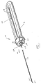
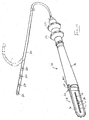
Fig. 1 shows a three dimensional view of an embodiment of a deflectable stylet; -
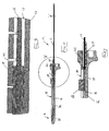
Fig. 2 shows a side view of a part of the stylet; -
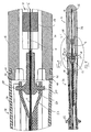
Fig. 3 shows a side view of a deflectable member of the stylet; -
Fig. 4 shows, on an enlarged scale, a sectional end view of the deflectable member taken along line IV-IV inFig.3 ; -
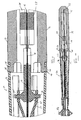
Fig. 5 shows a sectional side view of the stylet; -
Fig. 6 shows, on an enlarged scale, the part of the stylet surrounded by circle 'A' inFig. 5 ; -
Fig. 7 shows, on an enlarged scale, the part of the stylet surrounded by circle 'B' inFig. 5 ; -
Fig. 8 shows a sectional side view of an embodiment of a part of a catheter in its non-deflected configuration; -
Fig. 9 shows, on an enlarged scale, the part of the catheter surrounded by circle 'C' inFig. 8 ; -
Fig. 10 shows a sectional side view of the part of the catheter in its deflected configuration; -
Fig. 11 shows, on an enlarged scale, the part of the catheter surrounded by circle 'D' inFig. 10 ; and -
Fig. 12 shows a three dimensional view of the catheter assembly. - In the drawings,
reference 10 generally designates an embodiment of a deflectable stylet for a catheter. The deflectable stylet includes an elongate deflectable member in the form of asleeve 12 extending from a distal end of adeflection control mechanism 14. Thesleeve 12 defines a passage 13 (Fig. 4 ). Thestylet 12 further includes an actuator in the form of apull wire 16. Thepull wire 16 is received within thepassage 13 of thesleeve 12. A distal end 16.1 of thepull wire 16 is fast with a distal end 12.1 of thesleeve 12. A control member in the form of atube 18 is received over thepull wire 16 and is received in thepassage 13 of thesleeve 12, as will be described in greater detail below. - The
sleeve 12 is of a synthetic plastics material, more particularly, a polyetheretherketone (PEEK) plastics material. - A bend-enhancing region 20 (
Fig. 2 ) is defined at a distal part 12.2 of thesleeve 12. The bend-enhancingregion 20 comprises a plurality of longitudinally spaced, transversely extending slots 22 (Figs. 3 and 4 ) formed within a wall of thesleeve 12. Theslots 22 are formed, for example, by laser cutting a wall of thesleeve 12. As illustrated most clearly inFig. 4 of the drawings, eachslot 22 subtends an angle of less than 180°, more particularly about 150°. It will, however, be appreciated that eachslot 22 could subtend an angle greater than 180° and this would, to a greater or a lesser extent be dependent on the material from which thesleeve 12 is made. In this specification, the term "subtend", unless the context clearly indicates otherwise, is used in the sense of forming or marking the limits of the angle. - The
slots 22 are arranged in spacedgroups slots 22 could be arranged in a greater or a fewer number of groups as desired. - The group 24 of slots has the
slots 22 spaced more closely than theslots 22 of thegroup 26. Similarly, theslots 22 of thegroup 26 are spaced more closely together than theslots 22 of thegroup 28. - The
tube 18 is slidable relative to thesleeve 12 to occlude a greater or a fewer number ofslots 22. When thetube 18 is closer to the distal end 12.1 of thesleeve 12, theslots 22 of the group 24 are not occluded by thetube 18. By urging thesleeve 12 distally relative to thepull wire 16, a small radius of curvature deflection of the distal part 12.2 of thesleeve 12 occurs. When thetube 18 is pulled proximally relative to thesleeve 12 to expose theslots 22 of thegroup 26, a larger radius of curvature deflection of the distal part 12.2 of thesleeve 12 occurs by urging thesleeve 12 distally with respect to thepull wire 16. Further, when thetube 18 is pulled proximally further relative to thesleeve 12 to expose theslots 22 of thegroup 28, a still larger radius of curvature deflection of the distal part 12.2 of thesleeve 12 occurs when thesleeve 12 is urged distally relative to thepull wire 16. Thus, by varying the position of thetube 18 relative to thesleeve 12, a variable deflection of the distal part 12.2 of thesleeve 12 and, accordingly, a distal part of an electrode sheath 30 (Fig. 12 ) of acatheter 32 in which thestylet 10 is received occurs. This creates greater flexibility and versatility enabling a clinician more accurately to position a distal part of theelectrode sheath 30 of thecatheter 32. - The
tube 18 and thepull wire 16 are of a low cost material such as a stainless steel. Thus, thestylet 10, being made of low cost material, is a one-use product and can be disposed of after a single use. - The
deflection control mechanism 14 includes abody member 34 mountable to a proximal end of ahandle body 36 of thecatheter 32. Thebody member 34 has alongitudinally extending slot 38 defined in it in which thepull wire 16 is receivable as shown more clearly inFig. 5 of the drawings. - A distal end of the
body member 14 carries a mountingmember 40. The mountingmember 40 is displaceable axially relative to thebody member 34 in the direction ofarrows 42. The mountingmember 40 has a proximal end of thesleeve 12 connected to it. - A
boss 44 is arranged at a distal end of thebody member 34. An attachment formation in the form of a pair of opposed, radially outwardly extending pins 46 (Fig. 9 ) is carried by theboss 44. Thesepins 46 are received incomplementary receiving formations 48 in thehandle body 36 of thecatheter 32. As shown more clearly inFig. 12 of the drawings, each receivingformation 48 is in the form of an L-shaped slot in the proximal end of thehandle body 36 so that thebody member 34 of thedisplacement control mechanism 14 is attached to thehandle 36 bayonet fashion. - Similarly, the mounting
member 40 carries a pair of diametrically opposed, outwardly extending mounting pins 50. The mounting pins 50, in turn, engage a slide 52 (Figs. 8-11 ). Theslide 52 is connected to a displacement control member orknob 54 displaceably arranged on thehandle body 36 of thecatheter 32. Thedisplacement control member 54 is used to displace the mountingformation 40 in the direction ofarrows 42. In so doing, thesleeve 12 is displaced relative to thepull wire 16 to effect deflection of the distal part 12.2 of thesleeve 12. - The
pull wire 16 is anchored within thebody member 34 of thedisplacement control mechanism 14 at a proximal end of thebody member 34. Thus, as shown inFigs. 8 and10 of the drawings, a proximal end of the pull wire is anchored at 56 at a proximal end of thebody member 34 of thedeflection control mechanism 14. - A
slider 58 is received in theslot 38 of thebody member 34 of thedeflection control mechanism 14. Thetube 18 is attached to theslider 58 for effecting displacement of thetube 18 relative to thesleeve 12. Thus, by sliding the distal end of thetube 18 relative to thesleeve 12, as described above, the selected radius of curvature of deflection of the distal part 12.2 of thesleeve 12 can be achieved. - In
Figs. 8-12 of the drawings, an embodiment of acatheter 32 is illustrated. Thecatheter 32 includes theelectrode sheath 30 attached to a distal end of thehandle body 36. Theelectrode sheath 30 of thecatheter 32 is fabricated to have an unimpeded lumen. This is achieved by having conductors (not shown) forelectrodes 60 carried at the distal end of theelectrode sheath 30 embedded in a wall of theelectrode sheath 30. Thedeflectable stylet 10 is thus received within the lumen of theelectrode sheath 30 to effect deflection of the distal part of theelectrode sheath 30 as described above. - The
catheter 32 further includes aprojection control member 62 arranged distally of thedisplacement control member 54. Theprojection control member 62 is used to project the distal part of theelectrode sheath 30 relative to the distal part 12.2 of thedeflectable stylet 10 to extend the reach of theelectrode sheath 30 further. This further improves the versatility of thecatheter 32 using thedeflectable stylet 10. With this arrangement, a variable radius of curvature can be achieved plus the distal part of theelectrode sheath 30 can be projected relative to the distal part 12.2 of thesleeve 12 of thestylet 10 to enable theelectrode sheath 30 to access awkward to reach places in a patient's heart. - In the embodiment described above with reference to
Figs. 1-7 of the drawings, thestylet 10 has been described as having thetube 18 within thepassage 13 of thesleeve 12. In another embodiment, thetube 12 could, instead, be arranged outwardly of thesleeve 12. In this embodiment, thetube 18 is received within the lumen of theelectrode sheath 30 of thecatheter 32 separately or as part of thedeflectable stylet 10 with thesleeve 12 and itspull wire 16 being received within thetube 18. The effect of having the tube outside thesleeve 12 is the same as having thetube 18 within thepassage 13 of thesleeve 12. Thus, the variability of the radius of curvature of the distal part 12.2 is still controlled by manipulating the position of thetube 18 relative to thesleeve 12 using theslider 58 of thedisplacement control mechanism 14. - Hence, it is an advantage of the invention that a
deflectable stylet 10 is provided which has an adjustable radius of curvature of its distal part 12.2. This improves the versatility of acatheter 32 in which thedeflectable stylet 10 is received and gives the clinician more scope to manoeuvre and position the distal part of theelectrode sheath 30 of thecatheter 32. Further, by using theprojection control member 62 of thecatheter 32, the versatility of thecatheter 32 and the ability to position the distal part of theelectrode sheath 30 of thecatheter 32 at a desired location in a patient's heart is enhanced. In addition, thedeflectable stylet 10 is made of low cost material rendering it suitable for one-use applications without significant cost penalties. - It will be appreciated by persons skilled in the art that numerous variations and/or modifications may be made to the invention as shown in the specific embodiments without departing from the scope of the invention as broadly described. The present embodiments are, therefore, to be considered in all respects as illustrative and not restrictive.
Claims (16)
- A deflectable stylet for a catheter, the stylet including
an elongate deflectable member with a bend-enhancing region defined at a distal part of the deflectable member;
an actuator having a distal end fast with a distal end of the deflectable member, relative displacement between the actuator and the deflectable member causing deflection of the distal part of the deflectable member at the bend-enhancing region; and
a control member displaceably arranged relative to the deflectable member, the control member interacting with the bend-enhancing region of the deflectable member for controlling the extent of deflection of the distal part of the deflectable member. - The stylet of claim 1 in which the bend-enhancing region of the deflectable member is defined by a plurality of longitudinally spaced, transversely extending slots formed in the distal part of the deflectable member.
- The stylet of claim 2 in which the slots are arranged in groups.
- The stylet of claim 3 in which the spacing between the slots of one group differs with respect to the spacing between the slots of at least one other group.
- The stylet of any one of the preceding claims in which the control member is configured to impede the bend-enhancing region of the deflectable member for controlling the extent of deflection of the distal part of the deflectable member.
- The stylet of claim 5 in which the deflectable member comprises an elongate tubular member defining a passage with the control member being a tube received in the passage of the tubular member and the control member and the tubular member being slidably displaceable relative to each other to control the extent of deflection of the distal part of the deflectable member.
- The stylet of claim 5 in which the deflectable member comprises an elongate tubular member defining a passage with the control member being a sleeve received over the tubular member and the control member and the tubular member being slidably displaceable relative to each other to control the extent of deflection of the distal part of the deflectable member.
- The stylet of claim 6 or claim 7 in which the actuator is a pull wire, the pull wire being received in the passage of the tubular member.
- The stylet of any one of the preceding claims which includes a stiffening element for imparting torsional stiffness to the deflectable member.
- The stylet of any one of the preceding claims which includes a deflection control mechanism connectable to a catheter handle, the deflection control mechanism controlling relative axial displacement of the deflectable member, the actuator and the control member relative to each other.
- The stylet of claim 10 in which the deflection control mechanism includes a body member and a mounting formation for engaging a complementary receiving formation of the catheter handle, the mounting formation being displaceably arranged relative to the body member and the mounting formation acting on a deflection control element of the catheter handle and further mounting one of the deflectable member and the actuator, the body member of the deflection control mechanism defining an anchoring formation for anchoring the other of the actuator and the deflectable member.
- The stylet of claim 11 in which the deflection control mechanism further includes a mounting member displaceably arranged relative to the body member, the mounting member mounting a proximal end of the control member.
- A catheter assembly which includes
a handle having a handle body;
an electrode sheath extending from a distal end of the handle body, the electrode sheath defining a lumen; and
a deflectable stylet, as claimed in claim 11 or claim 12, arranged within the lumen of the electrode sheath. - The assembly of claim 13 in which the handle body defines a receiving formation for receiving an attachment formation of the deflection control mechanism of the stylet.
- The assembly of claim 14 in which the handle includes a deflection control member displaceably arranged relative to the handle body, the deflection control member including the engaging formation to be engaged by the mounting formation of the deflection control mechanism.
- The assembly of any one of claims 13 to 15 in which the control member of the stylet is received in the lumen of the electrode sheath, over the deflectable member, for imparting torsional stiffness to the deflectable member and to the electrode sheath.
Applications Claiming Priority (1)
| Application Number | Priority Date | Filing Date | Title |
|---|---|---|---|
| US93473607P | 2007-06-15 | 2007-06-15 |
Publications (3)
| Publication Number | Publication Date |
|---|---|
| EP2002859A2 true EP2002859A2 (en) | 2008-12-17 |
| EP2002859A3 EP2002859A3 (en) | 2009-12-09 |
| EP2002859B1 EP2002859B1 (en) | 2019-09-18 |
Family
ID=40134914
Family Applications (1)
| Application Number | Title | Priority Date | Filing Date |
|---|---|---|---|
| EP08252004.0A Active EP2002859B1 (en) | 2007-06-15 | 2008-06-10 | A deflectable stylet |
Country Status (7)
| Country | Link |
|---|---|
| US (1) | US8506562B2 (en) |
| EP (1) | EP2002859B1 (en) |
| JP (1) | JP5136936B2 (en) |
| CN (1) | CN101322865A (en) |
| AU (1) | AU2008202483B2 (en) |
| CA (1) | CA2635061A1 (en) |
| NZ (1) | NZ568920A (en) |
Cited By (2)
| Publication number | Priority date | Publication date | Assignee | Title |
|---|---|---|---|---|
| WO2015048682A1 (en) * | 2013-09-30 | 2015-04-02 | St. Jude Medical, Cardiology Division, Inc. | Catheter having an active return-to-straight mechanism |
| US11918762B2 (en) | 2018-10-03 | 2024-03-05 | St. Jude Medical, Cardiology Division, Inc. | Reduced actuation force electrophysiology catheter handle |
Families Citing this family (20)
| Publication number | Priority date | Publication date | Assignee | Title |
|---|---|---|---|---|
| WO2005042079A1 (en) * | 2003-10-31 | 2005-05-12 | Trudell Medical International | System and method for manipulating a catheter for delivering a substance to a body cavity |
| US8808345B2 (en) | 2008-12-31 | 2014-08-19 | Medtronic Ardian Luxembourg S.A.R.L. | Handle assemblies for intravascular treatment devices and associated systems and methods |
| JP5508804B2 (en) * | 2009-10-06 | 2014-06-04 | オリンパス株式会社 | Guide device |
| CA2863602A1 (en) * | 2011-05-04 | 2013-11-08 | The Regents Of The University Of Michigan | Intubation device |
| EP2908755B1 (en) | 2012-10-22 | 2019-04-17 | Medtronic Ardian Luxembourg S.à.r.l. | Catheters with enhanced flexibility |
| US9044575B2 (en) | 2012-10-22 | 2015-06-02 | Medtronic Adrian Luxembourg S.a.r.l. | Catheters with enhanced flexibility and associated devices, systems, and methods |
| JP5943810B2 (en) | 2012-10-31 | 2016-07-05 | 三菱重工マシナリーテクノロジー株式会社 | Tire electrical resistance measuring device |
| US9066726B2 (en) | 2013-03-15 | 2015-06-30 | Medtronic Ardian Luxembourg S.A.R.L. | Multi-electrode apposition judgment using pressure elements |
| WO2014189794A1 (en) | 2013-05-18 | 2014-11-27 | Medtronic Ardian Luxembourg S.A.R.L. | Neuromodulation catheters with shafts for enhanced flexibility and control and associated devices, systems, and methods |
| AU2014277623B2 (en) | 2013-06-07 | 2018-05-17 | Cathrx Ltd | An electrical lead for a catheter and method of manufacturing |
| US10149957B2 (en) * | 2013-10-03 | 2018-12-11 | University Of Utah Research Foundation | Tracheal intubation system including a laryngoscope |
| JP6246383B2 (en) | 2014-02-06 | 2017-12-13 | セント・ジュード・メディカル,カーディオロジー・ディヴィジョン,インコーポレイテッド | Elongated medical device with chamfered ring electrode and variable shaft |
| CN105686819B (en) * | 2014-11-27 | 2019-05-07 | 上海微创电生理医疗科技有限公司 | A kind of electrophysiologicalcatheter catheter |
| US10786651B2 (en) | 2017-03-07 | 2020-09-29 | Talon Medical, LLC | Steerable guide catheter |
| EP3903872A4 (en) * | 2018-12-29 | 2022-03-23 | Hangzhou Endonom Medtech Co., Ltd | Bendable catheter |
| CN112869747B (en) * | 2019-11-29 | 2022-11-25 | 清华大学 | Microelectrode, manufacturing method and using method thereof, plug device and microelectrode system |
| CA3183162A1 (en) | 2020-06-19 | 2021-12-23 | Jake Anthony Sganga | Systems and methods for guidance of intraluminal devices within the vasculature |
| CN112076379B (en) * | 2020-08-14 | 2021-06-18 | 北京邮电大学 | Hand-held multi-degree-of-freedom controllable intervention guide wire and intervention device |
| AU2022305235A1 (en) | 2021-07-01 | 2024-01-18 | Remedy Robotics, Inc. | Vision-based position and orientation determination for endovascular tools |
| US11707332B2 (en) | 2021-07-01 | 2023-07-25 | Remedy Robotics, Inc. | Image space control for endovascular tools |
Citations (2)
| Publication number | Priority date | Publication date | Assignee | Title |
|---|---|---|---|---|
| US5441483A (en) | 1992-11-16 | 1995-08-15 | Avitall; Boaz | Catheter deflection control |
| US5454787A (en) | 1991-02-15 | 1995-10-03 | Lundquist; Ingemar H. | Torquable tubular assembly and torquable catheter utilizing the same |
Family Cites Families (61)
| Publication number | Priority date | Publication date | Assignee | Title |
|---|---|---|---|---|
| US3539034A (en) * | 1966-10-11 | 1970-11-10 | Carl H Tafeen | Paracervical block anesthesia assembly |
| EP0132344A3 (en) | 1983-07-20 | 1986-01-22 | Purdue Research Foundation | Improved catheter based cardiac output sensor |
| US4718419A (en) | 1985-08-05 | 1988-01-12 | Olympus Optical Co., Ltd. | Snare assembly for endoscope |
| JPS62243566A (en) | 1986-03-26 | 1987-10-24 | シヤ−ウツド・メデイカル・カンパニ− | Preparatory moldable catheter |
| US4763647A (en) * | 1987-01-06 | 1988-08-16 | C. R. Bard, Inc. | Dual coil steerable guidewire |
| US4960134A (en) * | 1988-11-18 | 1990-10-02 | Webster Wilton W Jr | Steerable catheter |
| US6413234B1 (en) * | 1990-02-02 | 2002-07-02 | Ep Technologies, Inc. | Assemblies for creating compound curves in distal catheter regions |
| US5389080A (en) * | 1990-07-26 | 1995-02-14 | Yoon; Inbae | Endoscopic portal for use in endoscopic procedures and methods therefor |
| US5125896A (en) * | 1990-10-10 | 1992-06-30 | C. R. Bard, Inc. | Steerable electrode catheter |
| AU660444B2 (en) | 1991-02-15 | 1995-06-29 | Ingemar H. Lundquist | Torquable catheter and method |
| JP3135134B2 (en) * | 1991-04-19 | 2001-02-13 | オリンパス光学工業株式会社 | Flexible tube bending device |
| US5190050A (en) * | 1991-11-08 | 1993-03-02 | Electro-Catheter Corporation | Tip deflectable steerable catheter |
| US5275151A (en) * | 1991-12-11 | 1994-01-04 | Clarus Medical Systems, Inc. | Handle for deflectable catheter |
| CA2109980A1 (en) * | 1992-12-01 | 1994-06-02 | Mir A. Imran | Steerable catheter with adjustable bend location and/or radius and method |
| JPH06232944A (en) | 1993-02-02 | 1994-08-19 | Fuji Electric Co Ltd | Field equipment for process control |
| US5306245A (en) * | 1993-02-23 | 1994-04-26 | Advanced Surgical Inc. | Articulating device |
| US5364352A (en) * | 1993-03-12 | 1994-11-15 | Heart Rhythm Technologies, Inc. | Catheter for electrophysiological procedures |
| US5545200A (en) * | 1993-07-20 | 1996-08-13 | Medtronic Cardiorhythm | Steerable electrophysiology catheter |
| WO1995013111A1 (en) * | 1993-11-10 | 1995-05-18 | Medtronic Cadiorhythm | Electrode array catheter |
| US5358479A (en) * | 1993-12-06 | 1994-10-25 | Electro-Catheter Corporation | Multiform twistable tip deflectable catheter |
| US5395329A (en) * | 1994-01-19 | 1995-03-07 | Daig Corporation | Control handle for steerable catheter |
| US5882333A (en) * | 1994-05-13 | 1999-03-16 | Cardima, Inc. | Catheter with deflectable distal section |
| US6245068B1 (en) * | 1994-08-08 | 2001-06-12 | Scimed Life Systems, Inc. | Resilient radiopaque electrophysiology electrodes and probes including the same |
| US6071274A (en) * | 1996-12-19 | 2000-06-06 | Ep Technologies, Inc. | Loop structures for supporting multiple electrode elements |
| US5607392A (en) * | 1995-01-13 | 1997-03-04 | Ryder International Corporation | Fixed needle connector for IV assembly and method of assembling |
| WO1996026675A1 (en) * | 1995-02-28 | 1996-09-06 | Boston Scientific Corporation | Deflectable catheter for ablating cardiac tissue |
| US5656030A (en) | 1995-05-22 | 1997-08-12 | Boston Scientific Corporation | Bidirectional steerable catheter with deflectable distal tip |
| JP3766128B2 (en) | 1995-11-17 | 2006-04-12 | 株式会社東海理化電機製作所 | Sensor for body-insertable medical device and method for manufacturing the same |
| US6036707A (en) * | 1996-03-07 | 2000-03-14 | Devices For Vascular Intervention | Catheter device having a selectively flexible housing |
| JPH09285546A (en) | 1996-04-24 | 1997-11-04 | Nemoto Kyorindo:Kk | Catheter |
| US5826576A (en) * | 1996-08-08 | 1998-10-27 | Medtronic, Inc. | Electrophysiology catheter with multifunction wire and method for making |
| US5779708A (en) | 1996-08-15 | 1998-07-14 | Cyberdent, Inc. | Intraosseous drug delivery device and method |
| US6002955A (en) | 1996-11-08 | 1999-12-14 | Medtronic, Inc. | Stabilized electrophysiology catheter and method for use |
| US5843103A (en) | 1997-03-06 | 1998-12-01 | Scimed Life Systems, Inc. | Shaped wire rotational atherectomy device |
| US20030109778A1 (en) * | 1997-06-20 | 2003-06-12 | Cardiac Assist Devices, Inc. | Electrophysiology/ablation catheter and remote actuator therefor |
| US5861024A (en) * | 1997-06-20 | 1999-01-19 | Cardiac Assist Devices, Inc | Electrophysiology catheter and remote actuator therefor |
| EP0904797A3 (en) * | 1997-09-24 | 2000-08-09 | ECLIPSE SURGICAL TECHNOLOGIES, Inc. | Steerable catheter with tip alignment and surface contact detector |
| US6048339A (en) * | 1998-06-29 | 2000-04-11 | Endius Incorporated | Flexible surgical instruments with suction |
| US6319250B1 (en) * | 1998-11-23 | 2001-11-20 | C.R. Bard, Inc | Tricuspid annular grasp catheter |
| US6374476B1 (en) * | 1999-03-03 | 2002-04-23 | Codris Webster, Inc. | Method for making a catheter tip section |
| US20010007070A1 (en) * | 1999-04-05 | 2001-07-05 | Medtronic, Inc. | Ablation catheter assembly and method for isolating a pulmonary vein |
| US20020082594A1 (en) * | 1999-10-02 | 2002-06-27 | Cary Hata | Injectable biomaterial and methods for use thereof |
| US20030069570A1 (en) * | 1999-10-02 | 2003-04-10 | Witzel Thomas H. | Methods for repairing mitral valve annulus percutaneously |
| US6836687B2 (en) * | 2000-03-31 | 2004-12-28 | Medtronic, Inc. | Method and system for delivery of a medical electrical lead within a venous system |
| US6511471B2 (en) * | 2000-12-22 | 2003-01-28 | Biocardia, Inc. | Drug delivery catheters that attach to tissue and methods for their use |
| US6585718B2 (en) * | 2001-05-02 | 2003-07-01 | Cardiac Pacemakers, Inc. | Steerable catheter with shaft support system for resisting axial compressive loads |
| US6666864B2 (en) * | 2001-06-29 | 2003-12-23 | Scimed Life Systems, Inc. | Electrophysiological probes having selective element actuation and variable lesion length capability |
| US20030187389A1 (en) * | 2002-03-29 | 2003-10-02 | Scimed Life Systems, Inc. | Center support for steerable electrophysiology catheter |
| US7027852B2 (en) * | 2002-05-21 | 2006-04-11 | Pacesetter, Inc. | Lead with distal tip surface electrodes connected in parallel |
| US7033345B2 (en) * | 2002-05-21 | 2006-04-25 | Advanced Cardiovascular Systems, Inc. | Deflectable microimplant delivery system |
| US20050004515A1 (en) * | 2002-11-15 | 2005-01-06 | Hart Charles C. | Steerable kink resistant sheath |
| US7101361B2 (en) * | 2002-12-16 | 2006-09-05 | Medtronics, Inc. | Steerable medical device having means for imparting curves in the device and in elongated implantable medical instruments |
| KR100532671B1 (en) * | 2003-02-19 | 2005-12-01 | (주) 태웅메디칼 | Electrode device for high frequency thermotherapy |
| CN1882288A (en) * | 2003-11-25 | 2006-12-20 | 导管治疗有限公司 | A modular catheter |
| WO2005094661A1 (en) | 2004-03-30 | 2005-10-13 | Cathrx Ltd | A catheter steering device |
| US7717875B2 (en) * | 2004-07-20 | 2010-05-18 | St. Jude Medical, Atrial Fibrillation Division, Inc. | Steerable catheter with hydraulic or pneumatic actuator |
| EP1781363B1 (en) | 2004-08-05 | 2019-06-05 | Cathrx Ltd | A steerable catheter |
| US20060184105A1 (en) * | 2005-02-15 | 2006-08-17 | Townsend Gregory L | Thin wall catheter and method of placing same |
| EP1709987B1 (en) | 2005-04-07 | 2009-12-23 | Creganna Technologies Limited | Steerable catheter assembly |
| EP2046432B1 (en) * | 2006-08-04 | 2013-04-03 | Cathrx Ltd | A catheter handle assembly |
| CA2764859C (en) * | 2009-06-24 | 2018-09-25 | Shifamed, Llc | Steerable medical delivery devices and methods of use |
-
2008
- 2008-06-04 AU AU2008202483A patent/AU2008202483B2/en not_active Ceased
- 2008-06-06 NZ NZ568920A patent/NZ568920A/en unknown
- 2008-06-10 US US12/136,707 patent/US8506562B2/en active Active
- 2008-06-10 JP JP2008151959A patent/JP5136936B2/en active Active
- 2008-06-10 EP EP08252004.0A patent/EP2002859B1/en active Active
- 2008-06-13 CN CNA200810110156XA patent/CN101322865A/en active Pending
- 2008-06-13 CA CA002635061A patent/CA2635061A1/en not_active Abandoned
Patent Citations (2)
| Publication number | Priority date | Publication date | Assignee | Title |
|---|---|---|---|---|
| US5454787A (en) | 1991-02-15 | 1995-10-03 | Lundquist; Ingemar H. | Torquable tubular assembly and torquable catheter utilizing the same |
| US5441483A (en) | 1992-11-16 | 1995-08-15 | Avitall; Boaz | Catheter deflection control |
Cited By (3)
| Publication number | Priority date | Publication date | Assignee | Title |
|---|---|---|---|---|
| WO2015048682A1 (en) * | 2013-09-30 | 2015-04-02 | St. Jude Medical, Cardiology Division, Inc. | Catheter having an active return-to-straight mechanism |
| US10898686B2 (en) | 2013-09-30 | 2021-01-26 | St. Jude Medical, Cardiology Division, Inc. | Catheter having an active return-to-straight mechanism |
| US11918762B2 (en) | 2018-10-03 | 2024-03-05 | St. Jude Medical, Cardiology Division, Inc. | Reduced actuation force electrophysiology catheter handle |
Also Published As
| Publication number | Publication date |
|---|---|
| EP2002859A3 (en) | 2009-12-09 |
| AU2008202483A1 (en) | 2009-01-08 |
| NZ568920A (en) | 2009-11-27 |
| US20090125001A1 (en) | 2009-05-14 |
| US8506562B2 (en) | 2013-08-13 |
| CN101322865A (en) | 2008-12-17 |
| CA2635061A1 (en) | 2008-12-15 |
| JP5136936B2 (en) | 2013-02-06 |
| AU2008202483B2 (en) | 2011-07-14 |
| JP2008307385A (en) | 2008-12-25 |
| EP2002859B1 (en) | 2019-09-18 |
Similar Documents
| Publication | Publication Date | Title |
|---|---|---|
| EP2002859A2 (en) | A deflectable stylet | |
| EP2603272B1 (en) | A catheter assembly with deflection size adjustability | |
| EP2002858A2 (en) | Single use deflectable stylet | |
| JP6412505B2 (en) | Steerable guidewire and method of use | |
| EP2438954B1 (en) | Bi-directional catheter steering handle | |
| JP6050477B2 (en) | Steerable lumen punch | |
| EP1038545B1 (en) | Multi-directional steerable catheters and control handles | |
| EP1781363B1 (en) | A steerable catheter | |
| EP1038546B1 (en) | Multi-directional steerable catheters with control handle | |
| EP2777479B1 (en) | Improved catheter stiffness adjustment system | |
| EP3150243B1 (en) | Apparatus for accurately controlling needle extension | |
| WO2008144775A1 (en) | Extension control handle with adjustable locking mechanism | |
| US20220331560A1 (en) | Steerable sheath | |
| EP2983776B1 (en) | Steering control mechanism for catheter |
Legal Events
| Date | Code | Title | Description |
|---|---|---|---|
| PUAI | Public reference made under article 153(3) epc to a published international application that has entered the european phase |
Free format text: ORIGINAL CODE: 0009012 |
|
| 17P | Request for examination filed |
Effective date: 20080618 |
|
| AK | Designated contracting states |
Kind code of ref document: A2 Designated state(s): AT BE BG CH CY CZ DE DK EE ES FI FR GB GR HR HU IE IS IT LI LT LU LV MC MT NL NO PL PT RO SE SI SK TR |
|
| AX | Request for extension of the european patent |
Extension state: AL BA MK RS |
|
| RAP1 | Party data changed (applicant data changed or rights of an application transferred) |
Owner name: CATHRX LTD |
|
| PUAL | Search report despatched |
Free format text: ORIGINAL CODE: 0009013 |
|
| AK | Designated contracting states |
Kind code of ref document: A3 Designated state(s): AT BE BG CH CY CZ DE DK EE ES FI FR GB GR HR HU IE IS IT LI LT LU LV MC MT NL NO PL PT RO SE SI SK TR |
|
| AX | Request for extension of the european patent |
Extension state: AL BA MK RS |
|
| 17Q | First examination report despatched |
Effective date: 20100127 |
|
| AKX | Designation fees paid |
Designated state(s): AT BE BG CH CY CZ DE DK EE ES FI FR GB GR HR HU IE IS IT LI LT LU LV MC MT NL NO PL PT RO SE SI SK TR |
|
| STAA | Information on the status of an ep patent application or granted ep patent |
Free format text: STATUS: EXAMINATION IS IN PROGRESS |
|
| GRAP | Despatch of communication of intention to grant a patent |
Free format text: ORIGINAL CODE: EPIDOSNIGR1 |
|
| STAA | Information on the status of an ep patent application or granted ep patent |
Free format text: STATUS: GRANT OF PATENT IS INTENDED |
|
| INTG | Intention to grant announced |
Effective date: 20190307 |
|
| GRAJ | Information related to disapproval of communication of intention to grant by the applicant or resumption of examination proceedings by the epo deleted |
Free format text: ORIGINAL CODE: EPIDOSDIGR1 |
|
| STAA | Information on the status of an ep patent application or granted ep patent |
Free format text: STATUS: EXAMINATION IS IN PROGRESS |
|
| INTC | Intention to grant announced (deleted) | ||
| RIN1 | Information on inventor provided before grant (corrected) |
Inventor name: ANDERSON, NEIL LAWRENCE Inventor name: OGLE, DAVID |
|
| GRAR | Information related to intention to grant a patent recorded |
Free format text: ORIGINAL CODE: EPIDOSNIGR71 |
|
| GRAS | Grant fee paid |
Free format text: ORIGINAL CODE: EPIDOSNIGR3 |
|
| STAA | Information on the status of an ep patent application or granted ep patent |
Free format text: STATUS: GRANT OF PATENT IS INTENDED |
|
| GRAA | (expected) grant |
Free format text: ORIGINAL CODE: 0009210 |
|
| STAA | Information on the status of an ep patent application or granted ep patent |
Free format text: STATUS: THE PATENT HAS BEEN GRANTED |
|
| INTG | Intention to grant announced |
Effective date: 20190808 |
|
| AK | Designated contracting states |
Kind code of ref document: B1 Designated state(s): AT BE BG CH CY CZ DE DK EE ES FI FR GB GR HR HU IE IS IT LI LT LU LV MC MT NL NO PL PT RO SE SI SK TR |
|
| REG | Reference to a national code |
Ref country code: GB Ref legal event code: FG4D |
|
| REG | Reference to a national code |
Ref country code: CH Ref legal event code: EP |
|
| REG | Reference to a national code |
Ref country code: DE Ref legal event code: R096 Ref document number: 602008061207 Country of ref document: DE |
|
| REG | Reference to a national code |
Ref country code: AT Ref legal event code: REF Ref document number: 1180576 Country of ref document: AT Kind code of ref document: T Effective date: 20191015 |
|
| REG | Reference to a national code |
Ref country code: IE Ref legal event code: FG4D |
|
| REG | Reference to a national code |
Ref country code: NL Ref legal event code: MP Effective date: 20190918 |
|
| PG25 | Lapsed in a contracting state [announced via postgrant information from national office to epo] |
Ref country code: LT Free format text: LAPSE BECAUSE OF FAILURE TO SUBMIT A TRANSLATION OF THE DESCRIPTION OR TO PAY THE FEE WITHIN THE PRESCRIBED TIME-LIMIT Effective date: 20190918 Ref country code: HR Free format text: LAPSE BECAUSE OF FAILURE TO SUBMIT A TRANSLATION OF THE DESCRIPTION OR TO PAY THE FEE WITHIN THE PRESCRIBED TIME-LIMIT Effective date: 20190918 Ref country code: NO Free format text: LAPSE BECAUSE OF FAILURE TO SUBMIT A TRANSLATION OF THE DESCRIPTION OR TO PAY THE FEE WITHIN THE PRESCRIBED TIME-LIMIT Effective date: 20191218 Ref country code: BG Free format text: LAPSE BECAUSE OF FAILURE TO SUBMIT A TRANSLATION OF THE DESCRIPTION OR TO PAY THE FEE WITHIN THE PRESCRIBED TIME-LIMIT Effective date: 20191218 Ref country code: FI Free format text: LAPSE BECAUSE OF FAILURE TO SUBMIT A TRANSLATION OF THE DESCRIPTION OR TO PAY THE FEE WITHIN THE PRESCRIBED TIME-LIMIT Effective date: 20190918 Ref country code: SE Free format text: LAPSE BECAUSE OF FAILURE TO SUBMIT A TRANSLATION OF THE DESCRIPTION OR TO PAY THE FEE WITHIN THE PRESCRIBED TIME-LIMIT Effective date: 20190918 |
|
| REG | Reference to a national code |
Ref country code: LT Ref legal event code: MG4D |
|
| PG25 | Lapsed in a contracting state [announced via postgrant information from national office to epo] |
Ref country code: GR Free format text: LAPSE BECAUSE OF FAILURE TO SUBMIT A TRANSLATION OF THE DESCRIPTION OR TO PAY THE FEE WITHIN THE PRESCRIBED TIME-LIMIT Effective date: 20191219 Ref country code: LV Free format text: LAPSE BECAUSE OF FAILURE TO SUBMIT A TRANSLATION OF THE DESCRIPTION OR TO PAY THE FEE WITHIN THE PRESCRIBED TIME-LIMIT Effective date: 20190918 |
|
| REG | Reference to a national code |
Ref country code: AT Ref legal event code: MK05 Ref document number: 1180576 Country of ref document: AT Kind code of ref document: T Effective date: 20190918 |
|
| PG25 | Lapsed in a contracting state [announced via postgrant information from national office to epo] |
Ref country code: AT Free format text: LAPSE BECAUSE OF FAILURE TO SUBMIT A TRANSLATION OF THE DESCRIPTION OR TO PAY THE FEE WITHIN THE PRESCRIBED TIME-LIMIT Effective date: 20190918 Ref country code: NL Free format text: LAPSE BECAUSE OF FAILURE TO SUBMIT A TRANSLATION OF THE DESCRIPTION OR TO PAY THE FEE WITHIN THE PRESCRIBED TIME-LIMIT Effective date: 20190918 Ref country code: EE Free format text: LAPSE BECAUSE OF FAILURE TO SUBMIT A TRANSLATION OF THE DESCRIPTION OR TO PAY THE FEE WITHIN THE PRESCRIBED TIME-LIMIT Effective date: 20190918 Ref country code: PT Free format text: LAPSE BECAUSE OF FAILURE TO SUBMIT A TRANSLATION OF THE DESCRIPTION OR TO PAY THE FEE WITHIN THE PRESCRIBED TIME-LIMIT Effective date: 20200120 Ref country code: RO Free format text: LAPSE BECAUSE OF FAILURE TO SUBMIT A TRANSLATION OF THE DESCRIPTION OR TO PAY THE FEE WITHIN THE PRESCRIBED TIME-LIMIT Effective date: 20190918 Ref country code: IT Free format text: LAPSE BECAUSE OF FAILURE TO SUBMIT A TRANSLATION OF THE DESCRIPTION OR TO PAY THE FEE WITHIN THE PRESCRIBED TIME-LIMIT Effective date: 20190918 Ref country code: PL Free format text: LAPSE BECAUSE OF FAILURE TO SUBMIT A TRANSLATION OF THE DESCRIPTION OR TO PAY THE FEE WITHIN THE PRESCRIBED TIME-LIMIT Effective date: 20190918 Ref country code: ES Free format text: LAPSE BECAUSE OF FAILURE TO SUBMIT A TRANSLATION OF THE DESCRIPTION OR TO PAY THE FEE WITHIN THE PRESCRIBED TIME-LIMIT Effective date: 20190918 |
|
| PG25 | Lapsed in a contracting state [announced via postgrant information from national office to epo] |
Ref country code: SK Free format text: LAPSE BECAUSE OF FAILURE TO SUBMIT A TRANSLATION OF THE DESCRIPTION OR TO PAY THE FEE WITHIN THE PRESCRIBED TIME-LIMIT Effective date: 20190918 Ref country code: CZ Free format text: LAPSE BECAUSE OF FAILURE TO SUBMIT A TRANSLATION OF THE DESCRIPTION OR TO PAY THE FEE WITHIN THE PRESCRIBED TIME-LIMIT Effective date: 20190918 Ref country code: IS Free format text: LAPSE BECAUSE OF FAILURE TO SUBMIT A TRANSLATION OF THE DESCRIPTION OR TO PAY THE FEE WITHIN THE PRESCRIBED TIME-LIMIT Effective date: 20200224 |
|
| REG | Reference to a national code |
Ref country code: DE Ref legal event code: R097 Ref document number: 602008061207 Country of ref document: DE |
|
| PLBE | No opposition filed within time limit |
Free format text: ORIGINAL CODE: 0009261 |
|
| STAA | Information on the status of an ep patent application or granted ep patent |
Free format text: STATUS: NO OPPOSITION FILED WITHIN TIME LIMIT |
|
| PG2D | Information on lapse in contracting state deleted |
Ref country code: IS |
|
| PG25 | Lapsed in a contracting state [announced via postgrant information from national office to epo] |
Ref country code: DK Free format text: LAPSE BECAUSE OF FAILURE TO SUBMIT A TRANSLATION OF THE DESCRIPTION OR TO PAY THE FEE WITHIN THE PRESCRIBED TIME-LIMIT Effective date: 20190918 Ref country code: IS Free format text: LAPSE BECAUSE OF FAILURE TO SUBMIT A TRANSLATION OF THE DESCRIPTION OR TO PAY THE FEE WITHIN THE PRESCRIBED TIME-LIMIT Effective date: 20200119 |
|
| 26N | No opposition filed |
Effective date: 20200619 |
|
| PG25 | Lapsed in a contracting state [announced via postgrant information from national office to epo] |
Ref country code: SI Free format text: LAPSE BECAUSE OF FAILURE TO SUBMIT A TRANSLATION OF THE DESCRIPTION OR TO PAY THE FEE WITHIN THE PRESCRIBED TIME-LIMIT Effective date: 20190918 |
|
| PG25 | Lapsed in a contracting state [announced via postgrant information from national office to epo] |
Ref country code: MC Free format text: LAPSE BECAUSE OF FAILURE TO SUBMIT A TRANSLATION OF THE DESCRIPTION OR TO PAY THE FEE WITHIN THE PRESCRIBED TIME-LIMIT Effective date: 20190918 |
|
| REG | Reference to a national code |
Ref country code: CH Ref legal event code: PL |
|
| GBPC | Gb: european patent ceased through non-payment of renewal fee |
Effective date: 20200610 |
|
| PG25 | Lapsed in a contracting state [announced via postgrant information from national office to epo] |
Ref country code: LU Free format text: LAPSE BECAUSE OF NON-PAYMENT OF DUE FEES Effective date: 20200610 |
|
| REG | Reference to a national code |
Ref country code: BE Ref legal event code: MM Effective date: 20200630 |
|
| PG25 | Lapsed in a contracting state [announced via postgrant information from national office to epo] |
Ref country code: IE Free format text: LAPSE BECAUSE OF NON-PAYMENT OF DUE FEES Effective date: 20200610 Ref country code: LI Free format text: LAPSE BECAUSE OF NON-PAYMENT OF DUE FEES Effective date: 20200630 Ref country code: CH Free format text: LAPSE BECAUSE OF NON-PAYMENT OF DUE FEES Effective date: 20200630 Ref country code: FR Free format text: LAPSE BECAUSE OF NON-PAYMENT OF DUE FEES Effective date: 20200630 Ref country code: GB Free format text: LAPSE BECAUSE OF NON-PAYMENT OF DUE FEES Effective date: 20200610 |
|
| PG25 | Lapsed in a contracting state [announced via postgrant information from national office to epo] |
Ref country code: BE Free format text: LAPSE BECAUSE OF NON-PAYMENT OF DUE FEES Effective date: 20200630 |
|
| PG25 | Lapsed in a contracting state [announced via postgrant information from national office to epo] |
Ref country code: TR Free format text: LAPSE BECAUSE OF FAILURE TO SUBMIT A TRANSLATION OF THE DESCRIPTION OR TO PAY THE FEE WITHIN THE PRESCRIBED TIME-LIMIT Effective date: 20190918 Ref country code: MT Free format text: LAPSE BECAUSE OF FAILURE TO SUBMIT A TRANSLATION OF THE DESCRIPTION OR TO PAY THE FEE WITHIN THE PRESCRIBED TIME-LIMIT Effective date: 20190918 Ref country code: CY Free format text: LAPSE BECAUSE OF FAILURE TO SUBMIT A TRANSLATION OF THE DESCRIPTION OR TO PAY THE FEE WITHIN THE PRESCRIBED TIME-LIMIT Effective date: 20190918 |
|
| PGFP | Annual fee paid to national office [announced via postgrant information from national office to epo] |
Ref country code: DE Payment date: 20220620 Year of fee payment: 15 |
|
| REG | Reference to a national code |
Ref country code: DE Ref legal event code: R119 Ref document number: 602008061207 Country of ref document: DE |