EP2002064B1 - Multi-link bridge in undercarriage system - Google Patents
Multi-link bridge in undercarriage system Download PDFInfo
- Publication number
- EP2002064B1 EP2002064B1 EP07745805.7A EP07745805A EP2002064B1 EP 2002064 B1 EP2002064 B1 EP 2002064B1 EP 07745805 A EP07745805 A EP 07745805A EP 2002064 B1 EP2002064 B1 EP 2002064B1
- Authority
- EP
- European Patent Office
- Prior art keywords
- link
- roller frame
- frame
- center frame
- bridge
- Prior art date
- Legal status (The legal status is an assumption and is not a legal conclusion. Google has not performed a legal analysis and makes no representation as to the accuracy of the status listed.)
- Not-in-force
Links
Images


Classifications
-
- H—ELECTRICITY
- H10—SEMICONDUCTOR DEVICES; ELECTRIC SOLID-STATE DEVICES NOT OTHERWISE PROVIDED FOR
- H10P—GENERIC PROCESSES OR APPARATUS FOR THE MANUFACTURE OR TREATMENT OF DEVICES COVERED BY CLASS H10
- H10P72/00—Handling or holding of wafers, substrates or devices during manufacture or treatment thereof
- H10P72/10—Handling or holding of wafers, substrates or devices during manufacture or treatment thereof using carriers specially adapted therefor, e.g. front opening unified pods [FOUP]
- H10P72/19—Handling or holding of wafers, substrates or devices during manufacture or treatment thereof using carriers specially adapted therefor, e.g. front opening unified pods [FOUP] closed carriers
- H10P72/1908—Handling or holding of wafers, substrates or devices during manufacture or treatment thereof using carriers specially adapted therefor, e.g. front opening unified pods [FOUP] closed carriers specially adapted for containing substrates other than wafers
-
- E—FIXED CONSTRUCTIONS
- E02—HYDRAULIC ENGINEERING; FOUNDATIONS; SOIL SHIFTING
- E02F—DREDGING; SOIL-SHIFTING
- E02F9/00—Component parts of dredgers or soil-shifting machines, not restricted to one of the kinds covered by groups E02F3/00 - E02F7/00
- E02F9/02—Travelling-gear, e.g. associated with slewing gears
- E02F9/024—Travelling-gear, e.g. associated with slewing gears with laterally or vertically adjustable wheels or tracks
-
- B—PERFORMING OPERATIONS; TRANSPORTING
- B62—LAND VEHICLES FOR TRAVELLING OTHERWISE THAN ON RAILS
- B62D—MOTOR VEHICLES; TRAILERS
- B62D55/00—Endless track vehicles
- B62D55/08—Endless track units; Parts thereof
- B62D55/084—Endless-track units or carriages mounted separably, adjustably or extensibly on vehicles, e.g. portable track units
-
- H—ELECTRICITY
- H10—SEMICONDUCTOR DEVICES; ELECTRIC SOLID-STATE DEVICES NOT OTHERWISE PROVIDED FOR
- H10P—GENERIC PROCESSES OR APPARATUS FOR THE MANUFACTURE OR TREATMENT OF DEVICES COVERED BY CLASS H10
- H10P72/00—Handling or holding of wafers, substrates or devices during manufacture or treatment thereof
- H10P72/10—Handling or holding of wafers, substrates or devices during manufacture or treatment thereof using carriers specially adapted therefor, e.g. front opening unified pods [FOUP]
- H10P72/19—Handling or holding of wafers, substrates or devices during manufacture or treatment thereof using carriers specially adapted therefor, e.g. front opening unified pods [FOUP] closed carriers
- H10P72/1922—Handling or holding of wafers, substrates or devices during manufacture or treatment thereof using carriers specially adapted therefor, e.g. front opening unified pods [FOUP] closed carriers characterised by the construction of the closed carrier
Definitions
- the present invention relates to an undercarriage system, and more particularly, to a multi-link bridge in an undercarriage system, capable of preventing effectively an inclination of a roller frame in a vertical direction occurred from a load of a vehicle body and a condition of an uneven road surface and thus preventing an overturning of an excavator and a partial wear of a track thereby enhancing a service life and a feeling of riding by designing a center frame and the roller frame in an independent shape and connecting the center frame and the roller frame in an independent shape by the multi-link bridge so that both frame are independently movable in an up and down direction and a front and rear direction.
- an undercarriage system with a shape in which a center frame and a roller frame are connected to each other, of conventional excavators have had problems that if there are uneven road surfaces in a work place, an inclination of an overall excavator is occurred as the center frame and the roller frame are inclined simultaneously according to a condition of the uneven road surfaces and thus there are a dangerousness due to an overturning of a vehicle body, a decrease of a durability due to an accompanying partial wear by a load of a vehicle body and a decrease of a feeling of riding.
- JP S63 227481 A discloses a crawler type running device that is connected via a link member assembly with a machine body.
- the link member assembly is configured to even hold the machine body in a horizontal orientation when the crawler type running device is moved on a slope underground.
- JP H01 229780 A1 discloses a crawler belt type travelling unit that is connected to expandable legs of a machine undercarriage.
- the crawler belt type travelling unit can be rotated with respect to the machine body, such that the crawler belt type travelling unit may rotate with respect to the machine body.
- the present invention provides a multi-link bridge for an undercarriage system including a center frame and a roller frame of the undercarriage system which are designed independently from each other; link connection brackets installed respectively at opposite side surfaces of the center frame and the roller frame; and a link bridge coupled to the link connection brackets, for connecting the center frame and the roller frame, wherein the movement of the roller frame is independently from the center frame in an up and down or vertical direction and a front and rear or longitudinal direction.
- the link connection brackets may be installed in pairs with a predetermined distance on the opposite side surfaces of the center frame and the roller frame, and at least one pin hole for inserting a connection pin may be formed at the corresponding position.
- a plurality of the pin holes are formed with a predetermined distance at upper and lower portion of the each link connection bracket and a plurality of the link bridges is coupled in a laminated structure to each pin hole of the link connection bracket, thereby coupling the center frame and the roller frame in duplicate.
- the link bridge is provided with a link housing having a body, of which preferably both side surfaces adjoining the center frame and the roller frame are shaped in curved surface.
- the link bridge is further provided with two coupling holes which are formed in an inside of the body so as to pass through the body in parallel to each other and are adapted to contain the connection pin for connecting to the center frame and the roller frame; and the link connection pins which are formed with a diameter enough to be inserted into the coupling holes of the link housing and rotatably couple each of the link connection brackets of the center frame and the roller frame to each of the coupling holes of the link housing, and the coupling holes are formed with an inclined surface having a predetermined angle from a center portion of the housing of the link bridge toward an outside at an inner peripheral surface thereof, thereby enabling the roller frame connected to the center frame to rotates along the longitudinal direction of the frame by the inclined surface.
- An example not being part of the present invention also provides a multi-link bridge for an undercarriage system, in which a center frame and roller frames of the undercarriage system are connected by a plurality of link bridges, the link bridge is provided with a link housing having a body of which both side surfaces opposite the center frame and the roller frame are shaped in curved surface and coupling holes which are formed to pass through the body so as to contain a connection pin and the link connection pin coupled to the coupling hole of the link housing, and an inclined surface having a predetermined angle along a longitudinal direction of the coupling hole from a center portion of the housing of the link bridge toward an outside is formed at an inner peripheral surface of the coupling hole, thereby enabling the roller frame to rotate in a vertical direction and up and down along the longitudinal direction.
- a pigment mixed in melted resin is exemplary a flake type pigment in the present description; however it will be appreciated that besides the flake type a polyhedron type pigment or a different type of pigment may also be employed.
- Fig 1 is a perspective view illustrating an entire undercarriage system employing a multi-link bridge according to a preferred embodiment of the present invention
- Fig. 2 is an enlarged perspective view illustrating a structure of a connecting portion which connects a center frame and a roller frame of Fig. 1 ; shown is a state that two multi-link bridges 30 are coupled in a laminated structure to link connection brackets 11, 12, 21 and 22 so as to couple the center frame 10 and the roller frame 20 in duplicate, and shown is the undercarriage system in which a movement of the roller frame 20 is, as shown in Fig. 2 , independently from the center frame 10 in an up and down or vertical direction (direction A) and a front and rear or longitudinal direction (direction B) respectively.
- a preferred embodiment of the present invention includes the center frame 10 and the roller frame 20 of the undercarriage system which are designed independently from each other, link connection brackets 11, 12, 21 and 22 attached to opposite side surfaces of the center frame 10 and the roller frame 20 respectively, and a multi-link bridge 30 coupled to the link connection brackets 11, 12, 21 and 22, for connecting the center frame 10 and the roller frame 20 so as to enable a rotation movement in the vertical direction or the longitudinal direction.
- the link connection brackets 11, 12, 21 and 22 are at a predetermined distance from each other, attached in pairs to each opposite side surface of the center frame and the roller frame respectively and formed with a plurality of pin holes for inserting a connection pin.
- Figs. 3 to 5 are detailed views illustrating selected parts of the multi-link bridge in the undercarriage system according to the present invention and Fig. 6 is an operation state view illustrating a rotation operation of the roller frame in the longitudinal direction by the multi-link bridge.
- the link bridge 30 includes a link housing 31 having a body of which both side surfaces adjoining the center frame 10 and the roller frame 20 are shaped in curved surface and two coupling holes 33a and 33b which are formed in an inside of the body so as to pass through the body in parallel to each other and contain the connection pin for connecting to the center frame 10 and the roller frame 20, and the link connection pins 32a to 32d which are formed with a diameter enough to be inserted into the coupling holes 33a and 33b of the link housing 31 and rotatably couple each of the link connection brackets 11, 12, 21 and 22 of the center frame 10 and the roller frame 20 to each of the coupling holes 33a and 33b of the link housing 31.
- an inclined surface 34 having a predetermined angle ⁇ is formed in an inner peripheral surface of the coupling holes 33a and 33b along the longitudinal direction from a center portion of the housing 31 of the multi-link bridge 30 toward an outside and thereby enabling the roller frame 20 connected to the center frame 10 to rotate, as shown in Fig. 6 , with a space of the predetermined angle ⁇ to both upside and downside along the longitudinal direction of the frame (direction B in Fig. 2 ) by the inclined surface 34.
- the center frame 10 and the roller frame 20 of the present invention include the multi-link bridge 30 as shown in Figs. 1 and 2 and the multi-link bridge 30 is inserted between the pair of link connection brackets 11 and 12 which are attached to the side surface of the center frame 10 and the pair of link connection brackets 21 and 22 which are attached to the side surface of the roller frame 20, and the link connection brackets 11, 12, 21 and 22 and the multi-link bridge 30 are coupled by the plurality of the link connection pins 32a to 32d so as to accomplish coupling of the center frame 10 and the roller frame 20.
- the center frame 10 and the roller frame 20 interconnected by the multi-link bridge 30 are movable in the up and down direction independently from each other but are restricted to move in the lateral direction.
- both side surface thereof are shaped in a curved surface so as to avoid interference with the link connection brackets 11 and 12 of the center frame 10 and the link connection brackets 21 and 22 of the roller frame 20 when the link housing 31 is coupled to the link connection brackets 11 and 12 of the center frame 10 and the link connection brackets 21 and 22 of the roller frame 20, and the coupling holes 33a and 33b are formed to pass through side portions of the link housing 31 so as to receive the plurality of the link connection pins 32a to 32d.
- These coupling holes are horizontally formed in the longitudinal direction, are at a predetermined distance from each other, and coupled respectively by the link connection pins 32a to 32d to the pair of link connection brackets 11 and 12 which are attached to the side surface of the center frame 10 and the pair of link connection brackets 21 and 22 which are attached to the side surface of the roller frame 20.
- a front end portion of the link connection pins 32a to 32d is formed with a coupling groove 32e for fixing the end portion by a snap ring and the like which is not shown so as to prevent a separation of the link connection pins 32a to 32d after connecting the center frame 10 and the roller frame 20 by inserting the link connection pins 32a to 32d after disposing the link housing 31 between the link connection brackets 11 and 12 of the center frame 10 and the link connection brackets 21 and 22 of the roller frame 20.
- a reference symbol 32f which is not explained denotes a head of the link connection pins 32a to 32d.
- the coupling holes 33a and 33b are formed with the inclined surface 34 inclined at a predetermined angle ⁇ in the direction that the link connection pins 32a to 32d are inserted in, i.e. from a center portion of the coupling holes 33a and 33b toward both outside so as to be inclined in the up and down direction of the link housing 31.
- the angle of the inclined surface is greater than 0° and less than or equal to 30°.
- a diameter of the center portion of the coupling holes 33a and 33b is small and a diameter of the outside of the inclined surface 34, i.e. both inlet or outlet through which the connection pins 32a to 32d are inserted into or projected to is large.
- a rotation angle of the roller frame 20, which is made by the link connection pins 32a to 32d coupled to the coupling holes 33a and 33b of the link housing 31 and the inclined surface 34 of the link housing 31 and by which the roller frame 20 is rotated up and down from the longitudinal direction (or the traveling direction), would be greater than 0° and less than or equal to 30°.
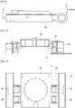
- Figs. 7 to 10 are a front view, a plan view, a side view and an operation state view illustrating a movement direction and rotation locking state of the roller frame in the undercarriage system according to the present invention.
- the track can maintain the horizontality as shown in Figs. 7 to 10 even if the roller frame 20 at right in the drawings is moved up as the road surface is uneven. This can be accomplished as the roller frame 20 is moved up independently from the center frame 10 by the multi-link bridge 30 connecting the center frame 10 and the roller frame 20. On the contrary, the right roller frame 20 may be moved down. Like the aforementioned, the roller frame 20 at left in the drawings may be vertically moved in the up and down direction in the same manner by the multi-link bridge 30.
- roller frame 20 connected to the center frame 10 by the multi-link bridge 30 is pivotable up an down by a predetermined angle as shown as the side views in Figs. 6 and 9 . This is accomplished by the inclined surface 34 of the coupling holes 33a and 33b of the link housing 31 as shown as a cross sectional view in Fig. 5 .
- the present invention restricts, firstly, a rotation of the roller frame 20 in relation to the center frame 10 around the longitudinal direction the (proceeding direction, refer to Fig. 7 ) and a rotation of the roller frame 20 in relation to the center frame 10 around the vertical direction the (refer to Fig. 8 ) and thus prevents an inclination of the vehicle body of an excavator in relation to an obstacle on the road surface so as to be capable of preventing an overturning of the vehicle body and improving operator's feeling of riding.
- the present invention is capable of preventing a partial wear of the track as the multi-link bridge 30 laterally disposed at the upper and lower portions of the connection portion maintains the roller frame 20 in parallel to the center frame 10 when the roller frame 20 which is independently from the center frame 10 is inclined in the horizontal direction and thus the track comes to contact horizontally with the ground (refer to Fig. 10 ).
- Fig. 11 is a plan view illustrating an undercarriage system according to another feature of the invention and shows a state that the center frame and the roller frames of the undercarriage system are connected by a plurality of the multi-link bridges 30 and 30' and particularly two pair of multi-link bridges are disposed respectively in front and rear sides in this embodiment.
- the multi-link bridge is, as described in detail with reference to Figs. 3 and 4 , formed with the link housing having a body of which both side surfaces opposite to the center frame and the roller frame are shaped in a curved surface and coupling holes formed to pass through the body so as to contain the link connection pins and the link connection pins coupled to the coupling holes, and constructed so that an inclined surface with the inclining angle is formed in the inner peripheral surface of the coupling holes along the longitudinal direction of the coupling holes from the center portion of the body toward the outsides and thus the roller frame rotates up and down along the vertical direction and the longitudinal direction.
- the roller frame 20 which is installed at both sides of the center frame 10 is connected by the multi-link bridge 30 to be movable in an up and down direction independently from the center frame 10 and the other side roller frame 20 and an up and down direction along the longitudinal direction of the roller frame 20, and therefore a horizontality of the track can be accomplished, service life of the track can be increased as the partial wear is prevented, a feeling of riding is enhanced as an impact due to the uneven road surface is not transferred directly to the center frame and dangerousness of the overturning can be reduced as the vehicle body is not entirely inclined.
- the present invention employs a link type part in the connection portion connecting the center frame and the roller frame in an undercarriage system and therefore capable of accomplishing effects of increasing the service life of the track by preventing a partial wear as maintaining a horizontality of the vehicle body of the excavator and also capable of improving operator's feeling of riding by stable traveling and thus enhancing working efficiency of the worker and so on.
Landscapes
- Engineering & Computer Science (AREA)
- Mining & Mineral Resources (AREA)
- Civil Engineering (AREA)
- General Engineering & Computer Science (AREA)
- Structural Engineering (AREA)
- Chemical & Material Sciences (AREA)
- Combustion & Propulsion (AREA)
- Transportation (AREA)
- Mechanical Engineering (AREA)
- Body Structure For Vehicles (AREA)
- Bridges Or Land Bridges (AREA)
- Jib Cranes (AREA)
Description
- The present invention relates to an undercarriage system, and more particularly, to a multi-link bridge in an undercarriage system, capable of preventing effectively an inclination of a roller frame in a vertical direction occurred from a load of a vehicle body and a condition of an uneven road surface and thus preventing an overturning of an excavator and a partial wear of a track thereby enhancing a service life and a feeling of riding by designing a center frame and the roller frame in an independent shape and connecting the center frame and the roller frame in an independent shape by the multi-link bridge so that both frame are independently movable in an up and down direction and a front and rear direction.
- Generally, an undercarriage system, with a shape in which a center frame and a roller frame are connected to each other, of conventional excavators have had problems that if there are uneven road surfaces in a work place, an inclination of an overall excavator is occurred as the center frame and the roller frame are inclined simultaneously according to a condition of the uneven road surfaces and thus there are a dangerousness due to an overturning of a vehicle body, a decrease of a durability due to an accompanying partial wear by a load of a vehicle body and a decrease of a feeling of riding.
-
JP S63 227481 A -
JP H01 229780 A1 - It is an object of the present invention, to solve the above problems, to provide a multi-link bridge in an undercarriage system capable of preventing a vibration and an inclination of a vehicle body occurred by a condition of an uneven road surface thereby enhancing operator's feeling of riding as well as preventing an overturning and capable of preventing a partial wear of a track thereby enhancing a durability by designing a center frame and a roller frame independently from each other and adding a plurality of links to the frame connecting portion so that the roller frame is relatively movable independently from the center frame in a up and down direction and a front and rear direction respectively.
- It is the object of the present invention to provide a multi-link bridge that enables rotation of a roller frame with respect to a center frame of an undercarriage system by utilizing simple and cost-efficient technical means.
- This object can be solved with the multi-link bridge according to claim 1. Improved embodiments of the invention are provided by the dependent claims.
- To achieve the object of the invention, the present invention provides a multi-link bridge for an undercarriage system including a center frame and a roller frame of the undercarriage system which are designed independently from each other; link
connection brackets installed respectively at opposite side surfaces of the center frame and the roller frame; and a link bridge coupled to the link connection brackets, for connecting the center frame and the roller frame, wherein the movement of the roller frame is independently from the center frame in an up and down or vertical direction and a front and rear or longitudinal direction. - The link connection brackets may be installed in pairs with a predetermined distance on the opposite side surfaces of the center frame and the roller frame, and at least one pin hole for inserting a connection pin may be formed at the corresponding position.
- In the multi-link bridge for an undercarriage system according to another aspect of the present invention, a plurality of the pin holes are formed with a predetermined distance at upper and lower portion of the each link connection bracket and a plurality of the link bridges is coupled in a laminated structure to each pin hole of the link connection bracket, thereby coupling the center frame and the roller frame in duplicate.
- In the multi-link bridge for an undercarriage system according to the present invention, the link bridge is provided with a link housing having a body, of which preferably both side surfaces adjoining the center frame and the roller frame are shaped in curved surface. According to the invention, the link bridge is further provided with two coupling holes which are formed in an inside of the body so as to pass through the body in parallel to each other and are adapted to contain the connection pin for connecting to the center frame and the roller frame; and the link connection pins which are formed with a diameter enough to be inserted into the coupling holes of the link housing and rotatably couple each of the link connection brackets of the center frame and the roller frame to each of the coupling holes of the link housing, and the coupling holes are formed with an inclined surface having a predetermined angle from a center portion of the housing of the link bridge toward an outside at an inner peripheral surface thereof, thereby enabling the roller frame connected to the center frame to rotates along the longitudinal direction of the frame by the inclined surface.
- An example not being part of the present invention also provides a multi-link bridge for an undercarriage system, in which a center frame and roller frames of the undercarriage system are connected by a plurality of link bridges, the link bridge is provided with a link housing having a body of which both side surfaces opposite the center frame and the roller frame are shaped in curved surface and coupling holes which are formed to pass through the body so as to contain a connection pin and the link connection pin coupled to the coupling hole of the link housing, and an inclined surface having a predetermined angle along a longitudinal direction of the coupling hole from a center portion of the housing of the link bridge toward an outside is formed at an inner peripheral surface of the coupling hole, thereby enabling the roller frame to rotate in a vertical direction and up and down along the longitudinal direction.
- The above and other objects, features and advantages of the present invention will become apparent from the following description of preferred embodiments given in conjunction with the accompanying drawings, in which:
-
Fig 1 is a perspective view illustrating an entire undercarriage system employing a multi-link bridge according to a preferred embodiment of the present invention; -
Fig. 2 is an enlarged perspective view illustrating a connecting portion which connects a center frame and a roller frame ofFig. 1 ; -
Figs. 3 to 5 are detailed views illustrating selected parts of the multi-link bridge in the undercarriage system according to the present invention; -
Fig. 6 is an operation state view illustrating a rotation operation of the roller frame in a front and rear direction or longitudinal direction by the multi-link bridge; -
Figs. 7 to 10 are a front view, a plan view, a side view and an operation state view illustrating a movement direction and rotation locking state of the roller frame in the undercarriage system according to the present invention; and -
Fig. 11 is a plan view illustrating an undercarriage system according to another feature of the invention. - Practical and presently preferred embodiments of the present invention are illustrative as shown in the following Examples. A pigment mixed in melted resin is exemplary a flake type pigment in the present description; however it will be appreciated that besides the flake type a polyhedron type pigment or a different type of pigment may also be employed.
-
Fig 1 is a perspective view illustrating an entire undercarriage system employing a multi-link bridge according to a preferred embodiment of the present invention andFig. 2 is an enlarged perspective view illustrating a structure of a connecting portion which connects a center frame and a roller frame ofFig. 1 ; shown is a state that twomulti-link bridges 30 are coupled in a laminated structure tolink connection brackets center frame 10 and theroller frame 20 in duplicate, and shown is the undercarriage system in which a movement of theroller frame 20 is, as shown inFig. 2 , independently from thecenter frame 10 in an up and down or vertical direction (direction A) and a front and rear or longitudinal direction (direction B) respectively. - As shown in the drawings, a preferred embodiment of the present invention includes the
center frame 10 and theroller frame 20 of the undercarriage system which are designed independently from each other,link connection brackets center frame 10 and theroller frame 20 respectively, and amulti-link bridge 30 coupled to thelink connection brackets center frame 10 and theroller frame 20 so as to enable a rotation movement in the vertical direction or the longitudinal direction. - The
link connection brackets -
Figs. 3 to 5 are detailed views illustrating selected parts of the multi-link bridge in the undercarriage system according to the present invention andFig. 6 is an operation state view illustrating a rotation operation of the roller frame in the longitudinal direction by the multi-link bridge. Thelink bridge 30 includes alink housing 31 having a body of which both side surfaces adjoining thecenter frame 10 and theroller frame 20 are shaped in curved surface and twocoupling holes center frame 10 and theroller frame 20, and thelink connection pins 32a to 32d which are formed with a diameter enough to be inserted into thecoupling holes link housing 31 and rotatably couple each of thelink connection brackets center frame 10 and theroller frame 20 to each of thecoupling holes link housing 31. - As shown in
Fig. 5 , aninclined surface 34 having a predetermined angle θ, preferably, greater than 0° and less than or equal to 30°,is formed in an inner peripheral surface of thecoupling holes housing 31 of themulti-link bridge 30 toward an outside and thereby enabling theroller frame 20 connected to thecenter frame 10 to rotate, as shown inFig. 6 , with a space of the predetermined angle θ to both upside and downside along the longitudinal direction of the frame (direction B inFig. 2 ) by theinclined surface 34. - In other words, the
center frame 10 and theroller frame 20 of the present invention include themulti-link bridge 30 as shown inFigs. 1 and 2 and themulti-link bridge 30 is inserted between the pair oflink connection brackets center frame 10 and the pair oflink connection brackets roller frame 20, and thelink connection brackets multi-link bridge 30 are coupled by the plurality of thelink connection pins 32a to 32d so as to accomplish coupling of thecenter frame 10 and theroller frame 20. In such the structure, thecenter frame 10 and theroller frame 20 interconnected by themulti-link bridge 30 are movable in the up and down direction independently from each other but are restricted to move in the lateral direction. - In the
link housing 31 constructing the body of themulti-link bridge 30, as shown inFigs. 3 to 5 , both side surface thereof are shaped in a curved surface so as to avoid interference with thelink connection brackets center frame 10 and thelink connection brackets roller frame 20 when thelink housing 31 is coupled to thelink connection brackets center frame 10 and thelink connection brackets roller frame 20, and thecoupling holes link housing 31 so as to receive the plurality of thelink connection pins 32a to 32d. These coupling holes are horizontally formed in the longitudinal direction, are at a predetermined distance from each other, and coupled respectively by thelink connection pins 32a to 32d to the pair oflink connection brackets center frame 10 and the pair oflink connection brackets roller frame 20. - Furthermore, a front end portion of the
link connection pins 32a to 32d is formed with acoupling groove 32e for fixing the end portion by a snap ring and the like which is not shown so as to prevent a separation of thelink connection pins 32a to 32d after connecting thecenter frame 10 and theroller frame 20 by inserting thelink connection pins 32a to 32d after disposing thelink housing 31 between thelink connection brackets center frame 10 and thelink connection brackets roller frame 20. Areference symbol 32f which is not explained denotes a head of thelink connection pins 32a to 32d. - The
coupling holes inclined surface 34 inclined at a predetermined angle θ in the direction that thelink connection pins 32a to 32d are inserted in, i.e. from a center portion of thecoupling holes link housing 31. Preferably, the angle of the inclined surface is greater than 0° and less than or equal to 30°. In other words, a diameter of the center portion of thecoupling holes inclined surface 34, i.e. both inlet or outlet through which theconnection pins 32a to 32d are inserted into or projected to is large. A rotation angle of theroller frame 20, which is made by thelink connection pins 32a to 32d coupled to thecoupling holes link housing 31 and theinclined surface 34 of thelink housing 31 and by which theroller frame 20 is rotated up and down from the longitudinal direction (or the traveling direction), would be greater than 0° and less than or equal to 30°. -
Figs. 7 to 10 are a front view, a plan view, a side view and an operation state view illustrating a movement direction and rotation locking state of the roller frame in the undercarriage system according to the present invention. - In the multi-link bridge of the undercarriage system according to the present invention in which the
multi-link bridges 30 are disposed in pairs at upper and lower sides of thelink connection brackets center frame 10 and theroller frame 20, the track can maintain the horizontality as shown inFigs. 7 to 10 even if the roller frame 20 at right in the drawings is moved up as the road surface is uneven. This can be accomplished as theroller frame 20 is moved up independently from thecenter frame 10 by themulti-link bridge 30 connecting thecenter frame 10 and theroller frame 20. On the contrary, theright roller frame 20 may be moved down. Like the aforementioned, theroller frame 20 at left in the drawings may be vertically moved in the up and down direction in the same manner by themulti-link bridge 30. - Meanwhile, the
roller frame 20 connected to thecenter frame 10 by themulti-link bridge 30 is pivotable up an down by a predetermined angle as shown as the side views inFigs. 6 and9 . This is accomplished by theinclined surface 34 of thecoupling holes link housing 31 as shown as a cross sectional view inFig. 5 . - In relation to an operation of a state that undercarriage system according to the present invention is assembled, in a case that a load of the vehicle body is transferring to the
center frame 10 when driving, the present invention restricts, firstly, a rotation of theroller frame 20 in relation to thecenter frame 10 around the longitudinal direction the (proceeding direction, refer toFig. 7 ) and a rotation of theroller frame 20 in relation to thecenter frame 10 around the vertical direction the (refer toFig. 8 ) and thus prevents an inclination of the vehicle body of an excavator in relation to an obstacle on the road surface so as to be capable of preventing an overturning of the vehicle body and improving operator's feeling of riding. - In addition, secondly, the present invention is capable of preventing a partial wear of the track as the
multi-link bridge 30 laterally disposed at the upper and lower portions of the connection portion maintains theroller frame 20 in parallel to thecenter frame 10 when theroller frame 20 which is independently from thecenter frame 10 is inclined in the horizontal direction and thus the track comes to contact horizontally with the ground (refer toFig. 10 ). -
Fig. 11 is a plan view illustrating an undercarriage system according to another feature of the invention and shows a state that the center frame and the roller frames of the undercarriage system are connected by a plurality of themulti-link bridges 30 and 30' and particularly two pair of multi-link bridges are disposed respectively in front and rear sides in this embodiment. - The multi-link bridge is, as described in detail with reference to
Figs. 3 and 4 , formed with the link housing having a body of which both side surfaces opposite to the center frame and the roller frame are shaped in a curved surface and coupling holes formed to pass through the body so as to contain the link connection pins and the link connection pins coupled to the coupling holes, and constructed so that an inclined surface with the inclining angle is formed in the inner peripheral surface of the coupling holes along the longitudinal direction of the coupling holes from the center portion of the body toward the outsides and thus the roller frame rotates up and down along the vertical direction and the longitudinal direction. - Therefore, a pitching in the proceeding direction is occurred when one multi-link bridge is used in the center of the roller frame, but the pitching in the front and rear direction can be prevented when two pair of the
multi-link bridges 30 and 30' are employed in the front and rear direction as shown inFig. 11 , thereby capable of enhancing the operator's feeling of riding as well as a stability. - In addition, wear of inner peripheral surface of the multi-link bridge and the pin supporting the multi-link bridge gets serious and this causes reduce in durability of the multi-link bridge when one multi-link bridge is disposed in the center of the roller frame, but load applied to each of the
multi-link bridges 30 and 30' can be dispersed when two pair of themulti-link bridges 30 and 30' are employed in the front and rear direction as shown inFig. 11 , thereby capable of increasing durability of the multi-link bridge. - In the present invention as described above, the
roller frame 20 which is installed at both sides of thecenter frame 10 is connected by themulti-link bridge 30 to be movable in an up and down direction independently from thecenter frame 10 and the otherside roller frame 20 and an up and down direction along the longitudinal direction of theroller frame 20, and therefore a horizontality of the track can be accomplished, service life of the track can be increased as the partial wear is prevented, a feeling of riding is enhanced as an impact due to the uneven road surface is not transferred directly to the center frame and dangerousness of the overturning can be reduced as the vehicle body is not entirely inclined. - As described above, the present invention employs a link type part in the connection portion connecting the center frame and the roller frame in an undercarriage system and therefore capable of accomplishing effects of increasing the service life of the track by preventing a partial wear as maintaining a horizontality of the vehicle body of the excavator and also capable of improving operator's feeling of riding by stable traveling and thus enhancing working efficiency of the worker and so on.
- Those skilled in the art will appreciate that the conceptions and specific embodiments disclosed in the foregoing description may be readily utilized as a basis for modifying or designing other embodiments for carrying out the same purposes of the present invention. Those skilled in the art will also appreciate that such equivalent embodiments do not depart from the spirit and scope of the invention as set forth in the appended claims.
Claims (5)
- A multi-link bridge for an undercarriage system, the undercarriage system comprising:a center frame (10) and a roller frame (20) which are designed independently from each other, wherein link connection brackets (11, 12, 21, 22) are installed respectively at opposite side surfaces of the center frame (10) and the roller frame (20);the multi-link bridge comprising:a link bridge (30) to be coupled to the link connection brackets (11, 12, 21, 22), for connecting the center frame (10) and the roller frame (20),wherein the link bridge (30) comprises a link housing (31) having a body with two coupling holes (33a, 33b) which are formed in an inside of the body so as to pass through the body in parallel to each other and are adapted to accommodate connection pins (32a, 32b) for connecting to the center frame (10) and the roller frame (20), wherein the link connection pins (32a, 32b) are formed with a diameter enough to be inserted into the coupling holes (33a, 33b) of the link housing (31) and rotatably couple each of the link connection brackets (11, 12, 21, 22) of the center frame (10) and the roller frame (20) to each of the coupling holes (33a, 33b) of the link housing (31),characterized in thatthe coupling holes (33a, 33b) are formed with an inclined surface (34) having a predetermined angle θ from a center portion of the link housing (31) toward an outside at an inner peripheral surface thereof, thereby enabling the roller frame (20) connected to the center frame (10) to rotate along a longitudinal direction B of the roller frame (10) by the inclined surface (34).
- The multi-link bridge for an undercarriage system according to claim 1, wherein the link connection brackets (11, 12, 21, 22) are installed in pairs with a predetermined distance on the opposite side surfaces of the center frame (10) and the roller frame (20), and at least one pin hole for inserting a connection pin (32a, 32b) is formed at the corresponding position.
- The multi-link bridge for an undercarriage system according to claim 2, wherein a plurality of the pin holes are formed with a predetermined distance at upper and lower portion of the each link connection bracket (11, 12, 21, 22) and a plurality of the link bridges (30) is coupled in a laminated structure to each pin hole of the link connection bracket (11, 12, 21, 22), thereby coupling the center frame (10) and the roller frame (20) in duplicate.
- The multi-link bridge for an undercarriage system according to claim 1, wherein both side surfaces of the body of the link housing (31) adjoining the center frame (10) and the roller frame (20) are shaped in curved surface.
- The multi-link bridge for an undercarriage system according to claim 1, wherein the inclined surface (34) of the coupling holes (33a, 33b) have the angle which is greater than 0° and less than or equal to 30°.
Applications Claiming Priority (2)
| Application Number | Priority Date | Filing Date | Title |
|---|---|---|---|
| KR1020060030910A KR100722654B1 (en) | 2006-04-05 | 2006-04-05 | Multi link bridge in undercarriage system |
| PCT/KR2007/001642 WO2007114644A1 (en) | 2006-04-05 | 2007-04-04 | Multi-link bridge in undercarriage system |
Publications (3)
| Publication Number | Publication Date |
|---|---|
| EP2002064A1 EP2002064A1 (en) | 2008-12-17 |
| EP2002064A4 EP2002064A4 (en) | 2014-05-07 |
| EP2002064B1 true EP2002064B1 (en) | 2017-06-07 |
Family
ID=38278459
Family Applications (1)
| Application Number | Title | Priority Date | Filing Date |
|---|---|---|---|
| EP07745805.7A Not-in-force EP2002064B1 (en) | 2006-04-05 | 2007-04-04 | Multi-link bridge in undercarriage system |
Country Status (6)
| Country | Link |
|---|---|
| US (1) | US8109351B2 (en) |
| EP (1) | EP2002064B1 (en) |
| JP (1) | JP5235861B2 (en) |
| KR (1) | KR100722654B1 (en) |
| CN (1) | CN101460683B (en) |
| WO (1) | WO2007114644A1 (en) |
Families Citing this family (10)
| Publication number | Priority date | Publication date | Assignee | Title |
|---|---|---|---|---|
| KR101370194B1 (en) | 2007-11-30 | 2014-03-06 | 두산인프라코어 주식회사 | Movable track apparatus having suspension function |
| WO2009128890A1 (en) * | 2008-04-14 | 2009-10-22 | Clark Equipment Company | Method of retaining structural transmission members of a tracked work vehicle |
| CA2693511C (en) | 2009-02-18 | 2016-02-23 | L'equipe Fabconcept Inc. | Vehicle suspension system |
| US8083014B1 (en) | 2010-06-09 | 2011-12-27 | Ronald Hall | Undercarriage for a tracked vehicle |
| JP5925213B2 (en) * | 2011-11-14 | 2016-05-25 | 日立建機株式会社 | Construction machine truck frame |
| CN103322127A (en) * | 2013-07-01 | 2013-09-25 | 杭州佳合舞台设备有限公司 | Tension-resisting and pressure-resisting chain device |
| USD756922S1 (en) * | 2014-02-03 | 2016-05-24 | Abb Technology Ag | Rotating electrical machinery modular air gap crawler |
| USD748053S1 (en) * | 2014-02-03 | 2016-01-26 | Abb Technology Ag | Rotating electrical machinery modular air gap crawler |
| US10711435B2 (en) * | 2016-08-03 | 2020-07-14 | Caterpillar Inc. | Frame assembly for machine |
| CN114411860A (en) * | 2022-02-10 | 2022-04-29 | 江苏徐工工程机械研究院有限公司 | Assembly type base of modular walking excavator |
Family Cites Families (22)
| Publication number | Priority date | Publication date | Assignee | Title |
|---|---|---|---|---|
| JPS588986Y2 (en) * | 1977-07-01 | 1983-02-18 | トキコ株式会社 | bearing bush |
| US4431074A (en) * | 1982-01-25 | 1984-02-14 | Fmc Corporation | Crane carbody and lower axle construction |
| DE3534626A1 (en) * | 1985-09-04 | 1987-03-12 | Schaeff Karl Gmbh & Co | Hydraulic excavator with adjustable track-laying gear |
| JPS63227481A (en) * | 1987-03-17 | 1988-09-21 | Kubota Ltd | Batsukuhou |
| JPS641077U (en) * | 1987-06-17 | 1989-01-06 | ||
| JPH01119486A (en) * | 1987-10-30 | 1989-05-11 | Komatsu Ltd | Tracked vehicle suspension system |
| JPH01229780A (en) * | 1988-03-09 | 1989-09-13 | Taisei Corp | Traveling equipment for construction machinery, etc. |
| JPH03143888A (en) | 1989-10-30 | 1991-06-19 | Toshiba Corp | Indicator for position of elevator |
| JPH03148387A (en) * | 1989-11-06 | 1991-06-25 | Yanmar Diesel Engine Co Ltd | Crawler type running gear |
| JP2873024B2 (en) * | 1989-11-06 | 1999-03-24 | ヤンマーディーゼル株式会社 | Vehicle width adjustment mechanism of crawler type traveling device |
| JP2653191B2 (en) * | 1989-11-20 | 1997-09-10 | 日産自動車株式会社 | Automotive pedal bearing structure |
| JPH061151U (en) * | 1992-06-22 | 1994-01-11 | 株式会社小松製作所 | Suspension device for tracked vehicle |
| JPH0796869A (en) * | 1993-09-29 | 1995-04-11 | Komatsu Ltd | Undercarriage of crawler type construction machine |
| DE9406572U1 (en) * | 1994-04-20 | 1994-10-06 | Teupen Maschinenbaugesellschaft mbH, 48599 Gronau | Chassis, in particular for mobile work equipment and vehicles |
| US5598896A (en) * | 1994-12-02 | 1997-02-04 | Caterpillar Inc. | Variable gage undercarriage arrangement |
| KR100224192B1 (en) | 1996-11-21 | 1999-10-15 | 정몽규 | Apparatus of supplying oil for an automobile |
| KR19980037445U (en) * | 1996-12-17 | 1998-09-15 | 추호석 | Track width adjusting device of tracked heavy equipment |
| JPH11334656A (en) * | 1998-05-28 | 1999-12-07 | Iwafuji Kogyo Kk | Crawler type traveling vehicle |
| KR20000015021U (en) * | 1998-12-31 | 2000-07-25 | 추호석 | Track angle adjusting device of tracked heavy equipment |
| JP4042942B2 (en) * | 1999-06-14 | 2008-02-06 | 株式会社小松製作所 | Track frame connection structure of work vehicle |
| JP2002087337A (en) * | 2000-09-20 | 2002-03-27 | Seirei Ind Co Ltd | Crawler type working vehicle |
| CN2755187Y (en) * | 2004-08-24 | 2006-02-01 | 上海彭浦巨力工程机械有限公司 | Walk hanger of crawler soil shifter |
-
2006
- 2006-04-05 KR KR1020060030910A patent/KR100722654B1/en not_active Expired - Fee Related
-
2007
- 2007-04-04 WO PCT/KR2007/001642 patent/WO2007114644A1/en not_active Ceased
- 2007-04-04 CN CN2007800206248A patent/CN101460683B/en not_active Expired - Fee Related
- 2007-04-04 EP EP07745805.7A patent/EP2002064B1/en not_active Not-in-force
- 2007-04-04 JP JP2009504123A patent/JP5235861B2/en not_active Expired - Fee Related
- 2007-04-04 US US12/294,830 patent/US8109351B2/en not_active Expired - Fee Related
Also Published As
| Publication number | Publication date |
|---|---|
| JP2009532274A (en) | 2009-09-10 |
| CN101460683A (en) | 2009-06-17 |
| JP5235861B2 (en) | 2013-07-10 |
| US20110036649A1 (en) | 2011-02-17 |
| CN101460683B (en) | 2011-08-31 |
| EP2002064A1 (en) | 2008-12-17 |
| EP2002064A4 (en) | 2014-05-07 |
| KR100722654B1 (en) | 2007-05-28 |
| US8109351B2 (en) | 2012-02-07 |
| WO2007114644A1 (en) | 2007-10-11 |
Similar Documents
| Publication | Publication Date | Title |
|---|---|---|
| US8109351B2 (en) | Multi-link bridge in undercarriage system | |
| US9604680B2 (en) | Truck frame for construction machine | |
| KR101863408B1 (en) | Track link and track device | |
| GB1562477A (en) | Four-track low ground pressure crawler vehicle | |
| US5494125A (en) | Track supporting roller apparatus | |
| CN100554599C (en) | Scraper installation structure of bulldozer | |
| US7992660B2 (en) | Crawler vehicle | |
| WO1998007613A1 (en) | Swivel working vehicle | |
| EP3392414B1 (en) | Main frame, front loader equipped with main frame, and work vehicle equipped with main frame | |
| CN103129636A (en) | Steerable crawler chassis of crawler construction machinery and disembarkation traveling system with same | |
| US5456331A (en) | Track supporting roller apparatus | |
| JPS62187606A (en) | Running vehicle | |
| JP2001158386A (en) | Working machine and method of assembling suspension assembly therefor | |
| CN100548772C (en) | Crawler frame assembly structure for construction machinery | |
| JP3399829B2 (en) | Swivel truck frame | |
| JP4175454B2 (en) | Crawler vehicle | |
| KR20210146186A (en) | Multi-link bridge of undercarriage system to improve worker's work efficiency | |
| EP2652211B1 (en) | Frame assembly and a method of manufacturing thereof | |
| JP2003252258A (en) | Traveling device and lower wheel for tracked vehicles | |
| JP5274542B2 (en) | Construction machine truck frame | |
| KR20150099911A (en) | Steering connected type front unit wheel fender of a agricultural vehicle | |
| JP2549488B2 (en) | Swivel frame of wheel crane | |
| JP2012020677A (en) | Truck frame of crawler type vehicle | |
| JPH06278431A (en) | Suspension device for vehicle | |
| KR101349585B1 (en) | Suspension apparatus for caterpillar of a heavy equipment |
Legal Events
| Date | Code | Title | Description |
|---|---|---|---|
| PUAI | Public reference made under article 153(3) epc to a published international application that has entered the european phase |
Free format text: ORIGINAL CODE: 0009012 |
|
| 17P | Request for examination filed |
Effective date: 20081010 |
|
| AK | Designated contracting states |
Kind code of ref document: A1 Designated state(s): AT BE BG CH CY CZ DE DK EE ES FI FR GB GR HU IE IS IT LI LT LU LV MC MT NL PL PT RO SE SI SK TR |
|
| DAX | Request for extension of the european patent (deleted) | ||
| A4 | Supplementary search report drawn up and despatched |
Effective date: 20140408 |
|
| RIC1 | Information provided on ipc code assigned before grant |
Ipc: E02F 9/02 20060101ALI20140402BHEP Ipc: B62D 55/084 20060101ALI20140402BHEP Ipc: E02F 9/08 20060101AFI20140402BHEP |
|
| GRAP | Despatch of communication of intention to grant a patent |
Free format text: ORIGINAL CODE: EPIDOSNIGR1 |
|
| STAA | Information on the status of an ep patent application or granted ep patent |
Free format text: STATUS: GRANT OF PATENT IS INTENDED |
|
| INTG | Intention to grant announced |
Effective date: 20161212 |
|
| GRAS | Grant fee paid |
Free format text: ORIGINAL CODE: EPIDOSNIGR3 |
|
| RAP1 | Party data changed (applicant data changed or rights of an application transferred) |
Owner name: DRB HOLDING CO., LTD. |
|
| GRAA | (expected) grant |
Free format text: ORIGINAL CODE: 0009210 |
|
| STAA | Information on the status of an ep patent application or granted ep patent |
Free format text: STATUS: THE PATENT HAS BEEN GRANTED |
|
| AK | Designated contracting states |
Kind code of ref document: B1 Designated state(s): AT BE BG CH CY CZ DE DK EE ES FI FR GB GR HU IE IS IT LI LT LU LV MC MT NL PL PT RO SE SI SK TR |
|
| REG | Reference to a national code |
Ref country code: GB Ref legal event code: FG4D |
|
| GRAA | (expected) grant |
Free format text: ORIGINAL CODE: 0009210 |
|
| REG | Reference to a national code |
Ref country code: CH Ref legal event code: EP Ref country code: AT Ref legal event code: REF Ref document number: 899321 Country of ref document: AT Kind code of ref document: T Effective date: 20170615 |
|
| REG | Reference to a national code |
Ref country code: IE Ref legal event code: FG4D |
|
| REG | Reference to a national code |
Ref country code: DE Ref legal event code: R096 Ref document number: 602007051242 Country of ref document: DE |
|
| REG | Reference to a national code |
Ref country code: NL Ref legal event code: MP Effective date: 20170607 |
|
| REG | Reference to a national code |
Ref country code: LT Ref legal event code: MG4D |
|
| PG25 | Lapsed in a contracting state [announced via postgrant information from national office to epo] |
Ref country code: LT Free format text: LAPSE BECAUSE OF FAILURE TO SUBMIT A TRANSLATION OF THE DESCRIPTION OR TO PAY THE FEE WITHIN THE PRESCRIBED TIME-LIMIT Effective date: 20170607 Ref country code: ES Free format text: LAPSE BECAUSE OF FAILURE TO SUBMIT A TRANSLATION OF THE DESCRIPTION OR TO PAY THE FEE WITHIN THE PRESCRIBED TIME-LIMIT Effective date: 20170607 Ref country code: FI Free format text: LAPSE BECAUSE OF FAILURE TO SUBMIT A TRANSLATION OF THE DESCRIPTION OR TO PAY THE FEE WITHIN THE PRESCRIBED TIME-LIMIT Effective date: 20170607 Ref country code: GR Free format text: LAPSE BECAUSE OF FAILURE TO SUBMIT A TRANSLATION OF THE DESCRIPTION OR TO PAY THE FEE WITHIN THE PRESCRIBED TIME-LIMIT Effective date: 20170908 |
|
| REG | Reference to a national code |
Ref country code: AT Ref legal event code: MK05 Ref document number: 899321 Country of ref document: AT Kind code of ref document: T Effective date: 20170607 |
|
| PG25 | Lapsed in a contracting state [announced via postgrant information from national office to epo] |
Ref country code: SE Free format text: LAPSE BECAUSE OF FAILURE TO SUBMIT A TRANSLATION OF THE DESCRIPTION OR TO PAY THE FEE WITHIN THE PRESCRIBED TIME-LIMIT Effective date: 20170607 Ref country code: BG Free format text: LAPSE BECAUSE OF FAILURE TO SUBMIT A TRANSLATION OF THE DESCRIPTION OR TO PAY THE FEE WITHIN THE PRESCRIBED TIME-LIMIT Effective date: 20170907 Ref country code: NL Free format text: LAPSE BECAUSE OF FAILURE TO SUBMIT A TRANSLATION OF THE DESCRIPTION OR TO PAY THE FEE WITHIN THE PRESCRIBED TIME-LIMIT Effective date: 20170607 Ref country code: LV Free format text: LAPSE BECAUSE OF FAILURE TO SUBMIT A TRANSLATION OF THE DESCRIPTION OR TO PAY THE FEE WITHIN THE PRESCRIBED TIME-LIMIT Effective date: 20170607 |
|
| PG25 | Lapsed in a contracting state [announced via postgrant information from national office to epo] |
Ref country code: SK Free format text: LAPSE BECAUSE OF FAILURE TO SUBMIT A TRANSLATION OF THE DESCRIPTION OR TO PAY THE FEE WITHIN THE PRESCRIBED TIME-LIMIT Effective date: 20170607 Ref country code: RO Free format text: LAPSE BECAUSE OF FAILURE TO SUBMIT A TRANSLATION OF THE DESCRIPTION OR TO PAY THE FEE WITHIN THE PRESCRIBED TIME-LIMIT Effective date: 20170607 Ref country code: CZ Free format text: LAPSE BECAUSE OF FAILURE TO SUBMIT A TRANSLATION OF THE DESCRIPTION OR TO PAY THE FEE WITHIN THE PRESCRIBED TIME-LIMIT Effective date: 20170607 Ref country code: AT Free format text: LAPSE BECAUSE OF FAILURE TO SUBMIT A TRANSLATION OF THE DESCRIPTION OR TO PAY THE FEE WITHIN THE PRESCRIBED TIME-LIMIT Effective date: 20170607 Ref country code: EE Free format text: LAPSE BECAUSE OF FAILURE TO SUBMIT A TRANSLATION OF THE DESCRIPTION OR TO PAY THE FEE WITHIN THE PRESCRIBED TIME-LIMIT Effective date: 20170607 |
|
| PG25 | Lapsed in a contracting state [announced via postgrant information from national office to epo] |
Ref country code: PL Free format text: LAPSE BECAUSE OF FAILURE TO SUBMIT A TRANSLATION OF THE DESCRIPTION OR TO PAY THE FEE WITHIN THE PRESCRIBED TIME-LIMIT Effective date: 20170607 Ref country code: IS Free format text: LAPSE BECAUSE OF FAILURE TO SUBMIT A TRANSLATION OF THE DESCRIPTION OR TO PAY THE FEE WITHIN THE PRESCRIBED TIME-LIMIT Effective date: 20171007 |
|
| REG | Reference to a national code |
Ref country code: DE Ref legal event code: R097 Ref document number: 602007051242 Country of ref document: DE |
|
| PLBE | No opposition filed within time limit |
Free format text: ORIGINAL CODE: 0009261 |
|
| STAA | Information on the status of an ep patent application or granted ep patent |
Free format text: STATUS: NO OPPOSITION FILED WITHIN TIME LIMIT |
|
| PG25 | Lapsed in a contracting state [announced via postgrant information from national office to epo] |
Ref country code: DK Free format text: LAPSE BECAUSE OF FAILURE TO SUBMIT A TRANSLATION OF THE DESCRIPTION OR TO PAY THE FEE WITHIN THE PRESCRIBED TIME-LIMIT Effective date: 20170607 |
|
| 26N | No opposition filed |
Effective date: 20180308 |
|
| PG25 | Lapsed in a contracting state [announced via postgrant information from national office to epo] |
Ref country code: SI Free format text: LAPSE BECAUSE OF FAILURE TO SUBMIT A TRANSLATION OF THE DESCRIPTION OR TO PAY THE FEE WITHIN THE PRESCRIBED TIME-LIMIT Effective date: 20170607 |
|
| REG | Reference to a national code |
Ref country code: DE Ref legal event code: R119 Ref document number: 602007051242 Country of ref document: DE |
|
| PG25 | Lapsed in a contracting state [announced via postgrant information from national office to epo] |
Ref country code: MC Free format text: LAPSE BECAUSE OF FAILURE TO SUBMIT A TRANSLATION OF THE DESCRIPTION OR TO PAY THE FEE WITHIN THE PRESCRIBED TIME-LIMIT Effective date: 20170607 |
|
| REG | Reference to a national code |
Ref country code: CH Ref legal event code: PL |
|
| REG | Reference to a national code |
Ref country code: BE Ref legal event code: MM Effective date: 20180430 |
|
| GBPC | Gb: european patent ceased through non-payment of renewal fee |
Effective date: 20180404 |
|
| REG | Reference to a national code |
Ref country code: IE Ref legal event code: MM4A |
|
| PG25 | Lapsed in a contracting state [announced via postgrant information from national office to epo] |
Ref country code: DE Free format text: LAPSE BECAUSE OF NON-PAYMENT OF DUE FEES Effective date: 20181101 Ref country code: LU Free format text: LAPSE BECAUSE OF NON-PAYMENT OF DUE FEES Effective date: 20180404 |
|
| PG25 | Lapsed in a contracting state [announced via postgrant information from national office to epo] |
Ref country code: GB Free format text: LAPSE BECAUSE OF NON-PAYMENT OF DUE FEES Effective date: 20180404 Ref country code: CH Free format text: LAPSE BECAUSE OF NON-PAYMENT OF DUE FEES Effective date: 20180430 Ref country code: LI Free format text: LAPSE BECAUSE OF NON-PAYMENT OF DUE FEES Effective date: 20180430 Ref country code: BE Free format text: LAPSE BECAUSE OF NON-PAYMENT OF DUE FEES Effective date: 20180430 |
|
| PG25 | Lapsed in a contracting state [announced via postgrant information from national office to epo] |
Ref country code: FR Free format text: LAPSE BECAUSE OF NON-PAYMENT OF DUE FEES Effective date: 20180430 Ref country code: IT Free format text: LAPSE BECAUSE OF NON-PAYMENT OF DUE FEES Effective date: 20180404 Ref country code: IE Free format text: LAPSE BECAUSE OF NON-PAYMENT OF DUE FEES Effective date: 20180404 |
|
| PG25 | Lapsed in a contracting state [announced via postgrant information from national office to epo] |
Ref country code: MT Free format text: LAPSE BECAUSE OF NON-PAYMENT OF DUE FEES Effective date: 20180404 |
|
| PG25 | Lapsed in a contracting state [announced via postgrant information from national office to epo] |
Ref country code: TR Free format text: LAPSE BECAUSE OF FAILURE TO SUBMIT A TRANSLATION OF THE DESCRIPTION OR TO PAY THE FEE WITHIN THE PRESCRIBED TIME-LIMIT Effective date: 20170607 |
|
| PG25 | Lapsed in a contracting state [announced via postgrant information from national office to epo] |
Ref country code: HU Free format text: LAPSE BECAUSE OF FAILURE TO SUBMIT A TRANSLATION OF THE DESCRIPTION OR TO PAY THE FEE WITHIN THE PRESCRIBED TIME-LIMIT; INVALID AB INITIO Effective date: 20070404 Ref country code: PT Free format text: LAPSE BECAUSE OF FAILURE TO SUBMIT A TRANSLATION OF THE DESCRIPTION OR TO PAY THE FEE WITHIN THE PRESCRIBED TIME-LIMIT Effective date: 20170607 |
|
| PG25 | Lapsed in a contracting state [announced via postgrant information from national office to epo] |
Ref country code: CY Free format text: LAPSE BECAUSE OF FAILURE TO SUBMIT A TRANSLATION OF THE DESCRIPTION OR TO PAY THE FEE WITHIN THE PRESCRIBED TIME-LIMIT Effective date: 20170607 |