EP2000882A1 - Installation destinée à la surveillance d'une condition environnementale et procédé de réglage automatique d'une unité d'affichage - Google Patents
Installation destinée à la surveillance d'une condition environnementale et procédé de réglage automatique d'une unité d'affichage Download PDFInfo
- Publication number
- EP2000882A1 EP2000882A1 EP08009343A EP08009343A EP2000882A1 EP 2000882 A1 EP2000882 A1 EP 2000882A1 EP 08009343 A EP08009343 A EP 08009343A EP 08009343 A EP08009343 A EP 08009343A EP 2000882 A1 EP2000882 A1 EP 2000882A1
- Authority
- EP
- European Patent Office
- Prior art keywords
- display unit
- brightness
- user
- camera
- detected
- Prior art date
- Legal status (The legal status is an assumption and is not a legal conclusion. Google has not performed a legal analysis and makes no representation as to the accuracy of the status listed.)
- Withdrawn
Links
Images


Classifications
-
- G—PHYSICS
- G06—COMPUTING OR CALCULATING; COUNTING
- G06F—ELECTRIC DIGITAL DATA PROCESSING
- G06F1/00—Details not covered by groups G06F3/00 - G06F13/00 and G06F21/00
- G06F1/26—Power supply means, e.g. regulation thereof
- G06F1/32—Means for saving power
- G06F1/3203—Power management, i.e. event-based initiation of a power-saving mode
-
- G—PHYSICS
- G06—COMPUTING OR CALCULATING; COUNTING
- G06F—ELECTRIC DIGITAL DATA PROCESSING
- G06F1/00—Details not covered by groups G06F3/00 - G06F13/00 and G06F21/00
- G06F1/26—Power supply means, e.g. regulation thereof
- G06F1/32—Means for saving power
- G06F1/3203—Power management, i.e. event-based initiation of a power-saving mode
- G06F1/3206—Monitoring of events, devices or parameters that trigger a change in power modality
- G06F1/3231—Monitoring the presence, absence or movement of users
-
- Y—GENERAL TAGGING OF NEW TECHNOLOGICAL DEVELOPMENTS; GENERAL TAGGING OF CROSS-SECTIONAL TECHNOLOGIES SPANNING OVER SEVERAL SECTIONS OF THE IPC; TECHNICAL SUBJECTS COVERED BY FORMER USPC CROSS-REFERENCE ART COLLECTIONS [XRACs] AND DIGESTS
- Y02—TECHNOLOGIES OR APPLICATIONS FOR MITIGATION OR ADAPTATION AGAINST CLIMATE CHANGE
- Y02D—CLIMATE CHANGE MITIGATION TECHNOLOGIES IN INFORMATION AND COMMUNICATION TECHNOLOGIES [ICT], I.E. INFORMATION AND COMMUNICATION TECHNOLOGIES AIMING AT THE REDUCTION OF THEIR OWN ENERGY USE
- Y02D10/00—Energy efficient computing, e.g. low power processors, power management or thermal management
Definitions
- the invention relates to an arrangement for monitoring an environmental condition, to a method for automatically adjusting an image brightness of a display unit of a VDU workstation and for automatically activating a power saving state of a display unit of a VDU workstation and the use of a computer with a display unit connected thereto and a web camera connected thereto.
- Common display units allow, among other things, the manual adjustment of brightness, contrast or color temperature to adapt their display to the needs of a user.
- a display device must be adapted to the prevailing lighting conditions.
- a display unit to which sunlight falls through a window requires settings other than a display unit whose working area is illuminated by overhead lighting.
- ergonomic Standards are respected so as not to endanger workers' health.
- an LCD monitor with a light detection function and a method of controlling the LCD monitor are known.
- the LCD monitor has a photosensor to detect a brightness of the ambient light.
- the LCD monitor can be turned off automatically to save energy when the photo sensor detects that there is no light source and the computer is in the course for a long time.
- Object of the present invention is therefore to describe arrangements and methods that make a simple, inexpensive and secure control of a display unit.
- the underlying object is achieved by an arrangement for monitoring an environmental condition comprising a display unit for displaying screen content, a camera for capturing image information in a user area of the display unit, and a control device operably coupled to the display device and the camera the control device is set up to acquire brightness data comprising ambient light conditions data at predetermined time intervals, perform a difference analysis between the detected brightness data, and to change the ambient light conditions and to set at least one brightness or contrast of the display unit based on the diffractive analysis.
- brightness data can be captured and analyzed without the use of an additional sensor, allowing for adjustment of brightness or contrast of a display unit even without an additional photosensor.
- the brightness or the contrast of the display unit is set as a function of the change in the ambient light conditions.
- the detection and analysis of changes in ambient light conditions allows automatic adjustment of brightness and / or contrast of a display unit.
- the brightness data comprise a spatial brightness distribution of the user area
- the difference analysis detects an active user within the user area.
- the display unit is switched to either an operating state or a power-saving state.
- ambient light conditions of a screen workstation are determined by using a camera, so that it is possible to automatically adjust the image brightness of the display unit.
- FIG. 1 shows a screen workstation 1 with a display unit 2.
- the display unit 2 is in the embodiment of a portable computer, the screen display 3 by a user to edit data displays.
- a camera 4 in the embodiment, a built-in CCD camera, integrated into the display unit 2.
- the camera 4 is set up to monitor a user area 5 of the screen workstation 1.
- the user area 5 is subdivided into a near area 6 and a far area 7.
- the user 2 is in the vicinity 6.
- the screen workstation 1 is illuminated by different light sources.
- daily light L shines into the user area 5.
- the intensity, the color temperature and the direction of incidence of the incident light depend, for example, on the position of the sun and the weather.
- the Eildtubariasplatz 1 is illuminated by a ceiling lighting 9 from above usually constant. However, it is also possible that the ceiling lighting 9 is either completely switched off or regulated, for example via a dimmer.
- further lighting elements may be present at the screen workstation 1. For example, it is possible to install a desk lamp or other light sources in the room.
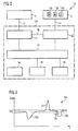
- FIG. 2 shows a schematic arrangement 10 comprising a camera 4, a control device 11, a graphics controller 12 and a display unit 2.
- the Control device 11 and the graphics controller 12 internal components of a computer 24, while the camera 1 and the display unit 2 are external components connected thereto.
- the display unit 2 includes operating parameters 13a, 13b, and 13c for adjusting the brightness, the contrast, and a power saving state of the display unit 2.
- the operation parameters 13a, 13b, and 13c are stored in the display unit 2.
- storage in the graphics controller 12 is also possible.
- connection 14 may be, for example, a cable for exchanging graphics and control data between a computer and a connected LCD monitor.
- a cable according to the so-called DDC (Display Data Chanel) standard is suitable for the transmission of operating parameters from a graphics controller 12 to a display unit 2.
- DDC Display Data Chanel
- other connections for example via a wireless WLAN interface according to a standard of the IEEE 802.11 family, or separate cables for transmitting display and control data are possible for coupling the display unit 2 and the graphics controller 12.
- the control device 11 is connected via further connections 15 and 16 with the camera 4 or the graphics controller 12.
- the control device 11 may be a processor of the computer 24, which is connected via a USB connection 15 to a so-called webcam.
- the processor of the computer 24 connected via another bus connection to a graphics card that serves as a graphics controller 12.
- the camera 4, the SLeuervorges 11, the graphics controller 12 and the display unit 2 may also be designed as wholly or partially integrated components.
- An operating system 17 running on the computer 24 can access both the controller 11 and the graphics controller 12. In this way, it is possible to display data of application programs 18 on the display unit 2. In addition, the application programs 18 or the operating system 17 itself can also make settings of the control device 11 and the graphics controller 12.
- control device 11 is set up to query brightness data from the camera 4 at regular time intervals via the connection 15. Based on the retrieved brightness data, the control device 11 determines an ambient condition of the VDU workstation 1.
- the controller 11 determines the ambient light situation caused by different light sources for a user of the assembly 10. Based on the determined ambient light situation, the controller 11 controls the graphics controller 12 such that appropriate operating parameters 13a, 13b and 13c corresponding to the detected ambient light conditions for the display unit 2 are selected. For example, the controller 11 may transmit a command to the graphics controller 12 that results in increasing or decreasing the brightness or contrast of the display unit 2.
- control apparatus 11 can access brightness data of individual image areas, such as a sub-matrix of the camera 4, a row or a column, and evaluate the data directly in the camera 4 or a buffer.
- FIG. 3 shows an exemplary brightness distribution 19 in which brightness data I are plotted over a location x.
- it may be the brightness distribution 19 of a single line of the camera 4.
- the brightness data I lies predominantly in a middle region 20.
- an intensity peak 21 and two shadow regions 22a and 22b can be seen in the brightness distribution 19.
- the intensity peak 21 can be an area with direct solar radiation, while the shadow areas 22a and 22b are caused by objects in the user area 5.
- a decrease in the intensity values of the brightness data I can be seen from right to left, which could be caused for example by unilateral sunshine.
- the middle area 20 which corresponds to the ambient light situation in the user area 5
- the control device 11 Since in the described embodiment, only one or a few lines of a CCD camera. 4
- identification of a user working in front of the computer is not readily possible. Its anonymity is therefore preserved.
- the amount of data to be transmitted via the connection 15 remains limited, so that also its subsequent processing is simplified.
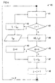
- FIG. 4 shows a flow chart of a method 40 for automatically setting an operating parameter 13, for example the image brightness or the contrast, of a display unit 2.
- a CCD matrix of a camera 4 can be read partially or completely by associated driver electronics and / or software.
- the determined brightness data I j are then processed by the camera 4 itself or a control device 11 assigned to the camera 4.
- a subsequent step 42 it is checked whether it is the first acquired brightness data I 1 or whether reference brightness values I ret already exist. If no brightness values I ret are still present, the first brightness values I 1 are stored in a step 43 as reference data I ret . Subsequently, the method 40 is continued in step 41.
- step 44 the currently detected brightness values I j are stored with the stored reference brightness values I ref compared.
- an ambient light condition can be determined. For example, it can be determined whether intensity peaks 21 and shadow areas 22 caused by intense sunlight fall into the user area 5, or whether uniform illumination is provided by a ceiling lighting 9.
- the detected ambient light conditions are compared with one or more predetermined threshold values A. If the ambient light conditions lie outside of limit values ⁇ for currently set operating parameters 13a, 13b or 13c, the operating parameters 13, in particular brightness or contrast, are changed in a step 46 in order to adapt the display unit 2 to the prevailing ambient light conditions. If the adjusted operating parameters 13a, 13b and 13c are suitable for a current ambient light situation, there is no change in the operating parameters 13 and the method is continued in step 47.
- the reference brightness data I ref is replaced by the current brightness data I j .
- optionally also optional step 48 possibly buffered image data or brightness data I j are deleted. This serves in particular for data protection and prevents an accumulation of unneeded image data.
- the method starts again in step 41 with the acquisition of new brightness data I j .
- one or more operating parameters 13 may be adjusted together or separately. For example, it is possible initially to adapt a brightness parameter 13a of a display element 2 to the prevailing ambient light conditions, and also to adjust a contrast parameter 13b of the display unit 2 in a subsequent scroll depending on the ambient light conditions and the adjusted image brightness.
- the display contrast of the display unit 2 should be adjusted down to allow a relaxed work on the screen workstation 1. In broad darkness, that is, without direct light irradiation on the screen workstation 1, both the display brightness and the display contrast of the display unit 2 can be reduced.
- the selected operating parameter or parameters 13 also depend on settings or operating modes of the operating system 17 or an application 18. For example, during a presentation, the image brightness may be increased, but the image contrast may be lowered to allow reading of image content from the far-end area 7. Conversely, when using a word processing program, the image brightness can be controlled down while the image contrast is increased.
- FIG. 5 shows another method 50 for automatically activating a power-saving state of a display unit 2.
- the steps 51, 52 and 53 largely correspond to the steps 41, 42 and 43 of the method 40.
- the steps 42 and 43 may also be dispensed with or made only once during the calibration of the arrangement 10 to form a static comparison image, a brightness distribution 19 or to deposit typical contrast ratios.
- step 54 the brightness values determined by the camera 4 are analyzed in another way.
- step 54 a presence of a user and / or a movement in the user area 5 observed by the camera 4 are detected.
- the shadow area 22b moves from right to left, which is indicated there by the arrow 23.
- This moved shadow area 22b corresponds to a shadow area caused by a user, which shadows different areas of the user area 5 by moving his head or his arm. It serves in the exemplary embodiment to detect both a presence and a movement of the user by the control device 11.
- a distinction between the near area 6 and the far area 7 can be made for further analysis of the movement.
- the controller 11 may use thresholds to separate two or more differently-spaced areas. If the user moves away from the proximity area 6, for example because he is taking a break, no active user is determined in step 55 on the basis of the preceding difference analysis, and in step 56 an energy saving function E is activated which turns the screen display 3 dark.
- the control device 11 detects in a further embodiment, a movement in the vicinity 6 and disables the energy saving function E of the display unit 2 in the optional step 57.
- reference data I ref and current data I j can again be interchanged or deleted before method 50, possibly delayed, restarts.
- one or more biometric features of a user are analyzed by the camera 4 before the display unit. 2 is returned from the energy-saving state back to an operating state.
- the eye relief, a head shape, a silhouette or a characteristic movement of the user can be determined by the analysis of one or more images of the camera 4.
- a control device 11 that analyzes brightness data I obtained by a camera 4 in the above-described manners, at the same time provides automatic adaptation of the display unit 2 to the prevailing ambient light conditions, can provide a power saving function E and / or a computer access protection function.
- a built-in a computer camera 4 or an attached web camera helps to avoid an additional sensor in the assembly 10.
- a portable computer with a built-in camera 4 may be used, wherein by uploading suitable software into the portable computer, a control device 11 is provided which enables the execution of a method 40 or 50 according to one of the above-mentioned embodiments.
Landscapes
- Engineering & Computer Science (AREA)
- Theoretical Computer Science (AREA)
- Physics & Mathematics (AREA)
- General Engineering & Computer Science (AREA)
- General Physics & Mathematics (AREA)
- Controls And Circuits For Display Device (AREA)
- Power Sources (AREA)
Applications Claiming Priority (1)
| Application Number | Priority Date | Filing Date | Title |
|---|---|---|---|
| DE102007025991A DE102007025991B4 (de) | 2007-06-04 | 2007-06-04 | Anordnung zum Überwachen einer Umgebungsbedingung und Verfahren zum automatischen Einstellen einer Anzeigeeinheit |
Publications (1)
| Publication Number | Publication Date |
|---|---|
| EP2000882A1 true EP2000882A1 (fr) | 2008-12-10 |
Family
ID=39651384
Family Applications (2)
| Application Number | Title | Priority Date | Filing Date |
|---|---|---|---|
| EP07119971A Withdrawn EP2000881A1 (fr) | 2007-06-04 | 2007-11-05 | Appareil électronique comprenant un dispositif de gestion de l'énergie, système informatique, procédé d'économie d'énergie et produit de programme informatique |
| EP08009343A Withdrawn EP2000882A1 (fr) | 2007-06-04 | 2008-05-21 | Installation destinée à la surveillance d'une condition environnementale et procédé de réglage automatique d'une unité d'affichage |
Family Applications Before (1)
| Application Number | Title | Priority Date | Filing Date |
|---|---|---|---|
| EP07119971A Withdrawn EP2000881A1 (fr) | 2007-06-04 | 2007-11-05 | Appareil électronique comprenant un dispositif de gestion de l'énergie, système informatique, procédé d'économie d'énergie et produit de programme informatique |
Country Status (2)
| Country | Link |
|---|---|
| EP (2) | EP2000881A1 (fr) |
| DE (1) | DE102007025991B4 (fr) |
Families Citing this family (7)
| Publication number | Priority date | Publication date | Assignee | Title |
|---|---|---|---|---|
| KR20090101852A (ko) | 2008-03-24 | 2009-09-29 | 소니 가부시끼 가이샤 | 액정 표시 장치 및 액정 표시 방법, 표시 제어 장치 및 표시 제어 방법 |
| JP5263092B2 (ja) | 2009-09-07 | 2013-08-14 | ソニー株式会社 | 表示装置および制御方法 |
| DE102012203197A1 (de) * | 2012-03-01 | 2013-09-05 | Siemens Aktiengesellschaft | Verfahren und System zum Steuern eines Prozesses |
| EP2901175B1 (fr) | 2012-12-10 | 2018-01-24 | Fujitsu Technology Solutions Intellectual Property GmbH | Dispositif electronique, procede de fonctionnement pour un dispositif electronique et utilisation d'un dispositif electronique |
| DE102013106699B3 (de) * | 2013-06-26 | 2014-02-27 | Fujitsu Technology Solutions Intellectual Property Gmbh | Computersystem mit einem Abwesenheitsmodus |
| WO2015117648A1 (fr) | 2014-02-05 | 2015-08-13 | Fujitsu Technology Solutions Intellectual Property Gmbh | Dispositif d'affichage, système informatique et procédé de gestion des états de fonctionnement d'un système informatique |
| CN109445563A (zh) * | 2018-10-19 | 2019-03-08 | 合肥享淘科技有限公司 | 一种计算机系统的节能方法及计算机系统 |
Citations (9)
| Publication number | Priority date | Publication date | Assignee | Title |
|---|---|---|---|---|
| US6518561B1 (en) * | 1999-11-05 | 2003-02-11 | Sony Corporation | User detection circuit with environmental light detector |
| DE10203157A1 (de) | 2002-01-28 | 2003-08-07 | Lite On Technology Co | LCD-Monitor mit Lichtdetektionsfunktion und ein Verfahren zum Steuern des LCD-Monitors |
| US6665805B1 (en) * | 1999-12-27 | 2003-12-16 | Intel Corporation | Method and apparatus for real time monitoring of user presence to prolong a portable computer battery operation time |
| US20040081337A1 (en) * | 2002-10-23 | 2004-04-29 | Tsirkel Aaron M. | Method and apparatus for adaptive realtime system power state control |
| US20050282561A1 (en) | 2004-06-21 | 2005-12-22 | Inventec Corporation | Interactive method for electronic equipment |
| US20050289363A1 (en) * | 2004-06-28 | 2005-12-29 | Tsirkel Aaron M | Method and apparatus for automatic realtime power management |
| EP1672460A1 (fr) * | 2004-12-15 | 2006-06-21 | STMicroelectronics (Research & Development) Limited | Dispositif de détection d'utilisateur d'ordinateur |
| US20060190750A1 (en) * | 2005-02-22 | 2006-08-24 | Logitech Europe S.A. | System power management based on motion detection |
| US20060204085A1 (en) * | 1999-10-29 | 2006-09-14 | Cooper Frederick J | Controlling processor-based systems using a digital camera |
Family Cites Families (4)
| Publication number | Priority date | Publication date | Assignee | Title |
|---|---|---|---|---|
| US5835083A (en) * | 1996-05-30 | 1998-11-10 | Sun Microsystems, Inc. | Eyetrack-driven illumination and information display |
| US6384852B1 (en) * | 1999-06-09 | 2002-05-07 | International Business Machines Corporation | Intelligent screen saver using image difference |
| US20050182962A1 (en) * | 2004-02-17 | 2005-08-18 | Paul Given | Computer security peripheral |
| US20060192775A1 (en) * | 2005-02-25 | 2006-08-31 | Microsoft Corporation | Using detected visual cues to change computer system operating states |
-
2007
- 2007-06-04 DE DE102007025991A patent/DE102007025991B4/de not_active Expired - Fee Related
- 2007-11-05 EP EP07119971A patent/EP2000881A1/fr not_active Withdrawn
-
2008
- 2008-05-21 EP EP08009343A patent/EP2000882A1/fr not_active Withdrawn
Patent Citations (9)
| Publication number | Priority date | Publication date | Assignee | Title |
|---|---|---|---|---|
| US20060204085A1 (en) * | 1999-10-29 | 2006-09-14 | Cooper Frederick J | Controlling processor-based systems using a digital camera |
| US6518561B1 (en) * | 1999-11-05 | 2003-02-11 | Sony Corporation | User detection circuit with environmental light detector |
| US6665805B1 (en) * | 1999-12-27 | 2003-12-16 | Intel Corporation | Method and apparatus for real time monitoring of user presence to prolong a portable computer battery operation time |
| DE10203157A1 (de) | 2002-01-28 | 2003-08-07 | Lite On Technology Co | LCD-Monitor mit Lichtdetektionsfunktion und ein Verfahren zum Steuern des LCD-Monitors |
| US20040081337A1 (en) * | 2002-10-23 | 2004-04-29 | Tsirkel Aaron M. | Method and apparatus for adaptive realtime system power state control |
| US20050282561A1 (en) | 2004-06-21 | 2005-12-22 | Inventec Corporation | Interactive method for electronic equipment |
| US20050289363A1 (en) * | 2004-06-28 | 2005-12-29 | Tsirkel Aaron M | Method and apparatus for automatic realtime power management |
| EP1672460A1 (fr) * | 2004-12-15 | 2006-06-21 | STMicroelectronics (Research & Development) Limited | Dispositif de détection d'utilisateur d'ordinateur |
| US20060190750A1 (en) * | 2005-02-22 | 2006-08-24 | Logitech Europe S.A. | System power management based on motion detection |
Also Published As
| Publication number | Publication date |
|---|---|
| DE102007025991A1 (de) | 2008-12-11 |
| EP2000881A1 (fr) | 2008-12-10 |
| DE102007025991B4 (de) | 2009-04-02 |
Similar Documents
| Publication | Publication Date | Title |
|---|---|---|
| EP2000882A1 (fr) | Installation destinée à la surveillance d'une condition environnementale et procédé de réglage automatique d'une unité d'affichage | |
| DE102008001391B4 (de) | Brandmeldervorrichtung sowie Verfahren zur Branddetektion | |
| DE102016100064B4 (de) | Adative Anzeige in B-Säule | |
| DE60028894T2 (de) | Präsentationssystem mit einer interaktiven Darstellung | |
| EP0793158B1 (fr) | Dispositif et méthode pour contrôler une jalousie | |
| WO2016058695A1 (fr) | Dispositif et procédé pour réduire l'éblouissement produit dans une pièce d'un bâtiment | |
| DE102016125862A1 (de) | Beleuchtungssystem und Steuervorrichtung | |
| DE102008039130A1 (de) | Durch ein neurales Netzwerk gesteuertes automatisches Verfolgungs- und Erkennungssystem und Verfahren | |
| EP2418517A2 (fr) | Capteur optoélectronique | |
| DE102016119343A1 (de) | Objektüberwachung mit Infrarotbildaufnahme und Infrarotpulsbeleuchtung | |
| DE112015003527T5 (de) | System und Verfahren zum Steuern einer Zielbeleuchtung für ein Abbildungs-Lesegerät | |
| EP2952661B1 (fr) | Procédé et dispositif d'ouverture sans contact d'un accès et/ou d'une sortie dans un véhicule de transport de passagers et véhicule de transport de passagers muni d'un tel dispositif | |
| WO2011124722A1 (fr) | Unité de détection multifonction pour déterminer des informations de contrôle pour la commande de lumière | |
| DE102016104362A1 (de) | Anpassen einer elektronischen anzeige auf grundlage von blickverfolgung | |
| DE102015215371A1 (de) | Fahrzeugbeleuchtungssteuersystem unter verwendung einer tragbaren brille und verfahren zum steuern desselben | |
| EP3587170A1 (fr) | Concept d'éclairage pour une station de recharge | |
| EP3318948B1 (fr) | Thermostat de radiateur | |
| EP4379494A1 (fr) | Thermostat de chauffage | |
| DE102021002164A1 (de) | Verfahren zum Beleuchten eines Fahrzeugs und angetriebenes oder gezogenes Fahrzeug | |
| DE69719295T2 (de) | Sonnenschutzvorrichtung | |
| EP2160033A1 (fr) | Installation de visiophone dotée d'une station extérieure détectant des personnes à l'aide d'une caméra | |
| DE102016119189A1 (de) | Verfahren zur Ansteuerung eines Ladegeräts sowie ein Ladegerät | |
| DE102019133835B3 (de) | Steuerung einer Innenausleuchtung eines Kraftfahrzeugs | |
| DE102014216053A1 (de) | Anpassung der Beleuchtungs-Wellenlänge bei der Augenerfassung | |
| DE102012103175A1 (de) | Gebäudeautomationsvorrichtung |
Legal Events
| Date | Code | Title | Description |
|---|---|---|---|
| PUAI | Public reference made under article 153(3) epc to a published international application that has entered the european phase |
Free format text: ORIGINAL CODE: 0009012 |
|
| AK | Designated contracting states |
Kind code of ref document: A1 Designated state(s): AT BE BG CH CY CZ DE DK EE ES FI FR GB GR HR HU IE IS IT LI LT LU LV MC MT NL NO PL PT RO SE SI SK TR |
|
| AX | Request for extension of the european patent |
Extension state: AL BA MK RS |
|
| 17P | Request for examination filed |
Effective date: 20090212 |
|
| 17Q | First examination report despatched |
Effective date: 20090311 |
|
| AKX | Designation fees paid |
Designated state(s): DE FR GB |
|
| STAA | Information on the status of an ep patent application or granted ep patent |
Free format text: STATUS: THE APPLICATION HAS BEEN WITHDRAWN |
|
| 18W | Application withdrawn |
Effective date: 20100715 |