EP2000798A2 - Dispositif et procédé d'inspection non-destructive d'objets allongés fabriqués en matériau magnétique tel qu'une corde métallique - Google Patents
Dispositif et procédé d'inspection non-destructive d'objets allongés fabriqués en matériau magnétique tel qu'une corde métallique Download PDFInfo
- Publication number
- EP2000798A2 EP2000798A2 EP08157320A EP08157320A EP2000798A2 EP 2000798 A2 EP2000798 A2 EP 2000798A2 EP 08157320 A EP08157320 A EP 08157320A EP 08157320 A EP08157320 A EP 08157320A EP 2000798 A2 EP2000798 A2 EP 2000798A2
- Authority
- EP
- European Patent Office
- Prior art keywords
- parameter
- elongated object
- magnetic field
- lmv
- behaviour
- Prior art date
- Legal status (The legal status is an assumption and is not a legal conclusion. Google has not performed a legal analysis and makes no representation as to the accuracy of the status listed.)
- Withdrawn
Links
Images


Classifications
-
- G—PHYSICS
- G01—MEASURING; TESTING
- G01N—INVESTIGATING OR ANALYSING MATERIALS BY DETERMINING THEIR CHEMICAL OR PHYSICAL PROPERTIES
- G01N27/00—Investigating or analysing materials by the use of electric, electrochemical, or magnetic means
- G01N27/72—Investigating or analysing materials by the use of electric, electrochemical, or magnetic means by investigating magnetic variables
- G01N27/82—Investigating or analysing materials by the use of electric, electrochemical, or magnetic means by investigating magnetic variables for investigating the presence of flaws
- G01N27/83—Investigating or analysing materials by the use of electric, electrochemical, or magnetic means by investigating magnetic variables for investigating the presence of flaws by investigating stray magnetic fields
- G01N27/87—Investigating or analysing materials by the use of electric, electrochemical, or magnetic means by investigating magnetic variables for investigating the presence of flaws by investigating stray magnetic fields using probes
Definitions
- the present invention refers to a device and method for non-destructive inspection of elongated objects made of magnetic material such as metallic ropes.
- this invention relates to a device according to the preamble of claim 1 and a to a method according to the preamble of claim 10.
- a disadvantage of a method and a device of the type mentioned above is that it supplies only a first and a second parameter which respectively are indicative of the loss of the volume of metal rope and the dispersion of magnetic flux located around the rope. Through these devices and methods it is not possible to obtain an output parameter indicative of the loss of metallic section of rope, which is an index of the seriousness of the defect in the rope.
- One purpose of this invention is to provide a device and a method which solve this problem of the prior art, and having, at the same time, a precise and reliable operation.
- Another purpose of the invention is to provide a device and a method that solve this problem by reducing oscillations of the metallic ropes during the inspection and mitigating the effects of disturbances arising out of such oscillations.
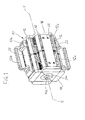
- FIG. 1 to 4 it is indicated by 10 a preferred embodiment, in accordance with this invention, of a device for the non-destructive inspection of elongated objects made of magnetic material, such as a metallic rope.
- the device 10 can be used not only for inspection of metallic ropes, but its scope can be extended to any other element of elongated shape of magnetic material.
- this device 10 includes four side yokes 12 made of magnetic material that are permanently interconnected at their frontal ends 12a and their rear ends 12b respectively through a frontal plate 14 and a rear plate 16 manufactured by non-magnetic material.
- the frontal plate 14 and the rear plate 16 are centrally provided with a frontal opening 14a and a rear opening 16a, respectively, for entry and exit of a metallic rope in or from the device 10.
- each lateral magnetic yoke 12 includes a frontal half-yoke 18a and a rear half-yoke 18b, between which there is placed an intermediate sensor group 20 including first magnetic field sensors 21, advantageously of Hall effect type.
- each frontal half-yoke 18a is coupled in the frontal part with a first slab permanent magnet 23a and the rear half-yoke 18b is coupled in the rear part with a second slab permanent magnet 23b.
- first slab permanent magnet 23a the rear half-yoke 18b is coupled in the rear part with a second slab permanent magnet 23b.
- the external plates 22 is provided with holding portions in the form of handles 22a.
- the frontal block 24 and rear block 28 are advantageously made of magnetic material, while the intermediate block 26 is preferably made of non-magnetic material.
- the three blocks 24, 26 and 28 are coupled with the internal faces 12d of the lateral yokes 12 and are advantageously made in the same size.
- the fastening on the lateral yokes 12 is advantageously carryied out by intermediate strips 30 made of rigid non-magnetic material.
- the intermediate strips 30 are connected to the rear half-yoke 18b (alternatively they could also be linked to the frontal semi-yoke 18a) near the intermediate sensor group 20.
- the front block 24, the intermediate block 26 and the rear block 28 present in their central portions respectively a front passing hole 24a, an intermediate passing hole 26a and a rear passing hole 28a.
- the front opening 14a, the front hole 24a, the intermediate hole 26a, the rear hole 28a and the rear opening 16a present a circular cross section and are aligned to a longitudinal axis XX.
- the device 10 forms a first and a second half-shell 10a and 10b divided by an oblique plan and hinged with each other around an axis OO.
- the frontal plate 14, the frontal block 24, the intermediate block 26, the rear block 28 and the rear plate 16 are diagonally interrupted by that oblique plan and hinged around the axis OO in correspondence with their respective corners aligned with each other.
- the device 10 may be opened to accommodate within it an elongated element of magnetic material, in this case a wire rope 32 ( Figures 6 and 7 ).
- a frontal bush 34 of cylindrical cross-section having an enlarged section 34a and a restricted section 34b, lies in the frontal opening 14a and in the frontal hole 24a.
- a rear bush 36 having an enlarged section 36a and a restricted section 36b, lies in the rear opening 16a and the real hole 28a.
- intermediate cylindrical bush 38 made of non-magnetic material (e.g. plastic) lies in an intermediate hole 26a.
- a set of second magnetic field sensors are circumferentially placed on the internal surface of the intermediate cylindrical bush 38.
- first and second magnetic field sensors 21 and 40 may also be different, such as electromagnetic sensors with coils or equivalent.
- the intermediate bush 38 is connected with a control unit (not shown) associated with the device 10 through connectors 38b projecting externally and coupled to their relative socket (not shown) in the intermediate block 26.
- the particular structure of the device 10 allows to receive a plurality of frontal bushes 34, a plurality of rear bushes 36 and a plurality of intermediate bushes 38, with respective different internal diameters.
- the choice of the intermediate bush 26 is finalised to reduce the distance between the set of second magnetic field sensors 40 and the metallic rope 32. In this way, the first and second magnetic field sensors 21 and 40 allow to obtain measurements more reliable and accurate.
- the bushes 34, 36 and 38 have the shape of a cylindrical hole and in Figures 4 and 5 are shown cut along a longitudinal plane.
- the bushes 34, 36 and 38 may also be implemented in a single monolithic piece, for example by moulding the intermediate bush 38 on the frontal bush 34 and the rear bush 36.
- each of these bushes 34, 36 and 38 can be made in the form of a pair of half-bushes suitable for coupling to each of the half shells 10a and 10b.
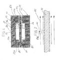
- Figure 6 are schematically illustrated two of the four magnetic circuits made from the device 10 through the lateral magnetic yokes 12, where the arrows indicate the path of the magnetic flux.
- a first magnetic flux ⁇ 1 exits radially from a first permanent magnet 23a and enters in the part of the metallic rope 32 located at the frontal block 24. Subsequently, a second magnetic flux ⁇ 2 axially flows through the metallic rope 32 in order to reach the magnetic saturation.
- the third magnetic flux ⁇ 3 exits radially from the part of the metallic rope 32 which is located at the rear block 28 and enters in the corresponding second permanent magnet 23b.
- the fourth magnetic flux ⁇ 4 exits from the second permanent magnet 23b, enters into the lateral magnetic yoke 12, which is axially crossed to close the magnetic circuit on the second permanent magnet 23a.
- each of the four sides of the device 10 identified by each lateral yoke 12, occurs the same situation in terms of magnetic flux.
- the magnetic flux ⁇ 4 is indicative of the volume of metallic rope 32 which flows through the device 10 in the section between the frontal block 24 and the rear block 28.
- LMV Loss of Metallic Volume
- the first parameter LMV it is calculated an average value of the field measurements obtained by each of the intermediate sensor groups 20 of the individual lateral yokes 12. In this way it is possible to mitigate the effects of eventual disturbs due to possible fluctuations of the metallic rope 32 in the internal chamber of the device 10.
- the second magnetic field sensors 40 circumferentially located near the metallic rope 32 are predisposed to measure - at the intermediate block 26 - a leakage component of the second magnetic flux ⁇ 2.
- the leakage component is indicative of small defects (e.g. broken wire) located in the cross section of the metallic rope 32 when passing through the intermediate block 26.
- the second magnetic field sensors 40 allow a measurement of a second parameter LF (Localized Fault) for the entire length of metallic rope that runs inside the device 10 during the inspection.
- LF Localized Fault
- the second parameter LF is the average value on the measurement set obtained from each of the second magnetic field sensors 40 of the intermediate bush 38.
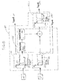
- FIG. 8 is a block diagram of the control unit 41.
- the control unit 41 includes a first, a second, a third memory 42, 44, 45 and a processing unit 46.
- the control unit 41 which may be included in or linked to the device 10, receives, at predetermined intervals, signals related to the parameters LMV and LF, respectively generated by the first and second magnetic field sensors 21 and 40.
- the behaviour of the parameters LMV and LF are stored according to the position of the metallic rope 32 enclosed by the device 10, respectively in the first and second memory 42, 44 of the control unit 41.
- the processing unit 46 receives data of the second parameter LF stored by the second memory 44, identifying the relative minimum (xmin, LFmin) and the relative maximum (xmax, LFmax) of the leakage magnetic field component, where xmin and xmax represent a first and a second point on the metallic rope 32, which are associated respectively to the values LFmin and LFmax.
- the processing unit 46 determines a third parameter ⁇ x, indicative of the length of the defect in the metallic rope 32.
- this third parameter ⁇ x is obtained in proportion to the distance between xmax and xmin.
- the processing unit 46 receives data of the first parameter LMV stored by the first memory 42 and processes them according to the third parameter ⁇ x, so as to obtain an output signal called LMA (Loss of Metallic Area), representative of the missing cross section of metallic rope 32.
- LMA Loss of Metallic Area
- data from the first parameter LMV, in the part of the metallic rope where is detected the presence of a defect are divided by the third parameter ⁇ x.
- the data of developments in the fourth parameter LMA generated in this way are stored in the third memory 45.
- control unit 41 provides the signals LF, LMV and LMA, obtained as described above, to additional external devices, not shown, (for example for display on a video or paper).
Landscapes
- Chemical & Material Sciences (AREA)
- Chemical Kinetics & Catalysis (AREA)
- Electrochemistry (AREA)
- Physics & Mathematics (AREA)
- Health & Medical Sciences (AREA)
- Life Sciences & Earth Sciences (AREA)
- Analytical Chemistry (AREA)
- Biochemistry (AREA)
- General Health & Medical Sciences (AREA)
- General Physics & Mathematics (AREA)
- Immunology (AREA)
- Pathology (AREA)
- Investigating Or Analyzing Materials By The Use Of Magnetic Means (AREA)
Applications Claiming Priority (1)
| Application Number | Priority Date | Filing Date | Title |
|---|---|---|---|
| ITTO20070385 ITTO20070385A1 (it) | 2007-06-04 | 2007-06-04 | Dispositivo e metodo per ispezionare in modo non distruttivo un elemento allungato di materiale conduttore magnetico, quale una fune metallica |
Publications (2)
| Publication Number | Publication Date |
|---|---|
| EP2000798A2 true EP2000798A2 (fr) | 2008-12-10 |
| EP2000798A3 EP2000798A3 (fr) | 2010-12-29 |
Family
ID=39734100
Family Applications (1)
| Application Number | Title | Priority Date | Filing Date |
|---|---|---|---|
| EP08157320A Withdrawn EP2000798A3 (fr) | 2007-06-04 | 2008-05-30 | Dispositif et procédé d'inspection non-destructive d'objets allongés fabriqués en matériau magnétique tel qu'une corde métallique |
Country Status (2)
| Country | Link |
|---|---|
| EP (1) | EP2000798A3 (fr) |
| IT (1) | ITTO20070385A1 (fr) |
Cited By (2)
| Publication number | Priority date | Publication date | Assignee | Title |
|---|---|---|---|---|
| CN107091876A (zh) * | 2017-03-06 | 2017-08-25 | 深圳市华大智能科技有限公司 | 铁磁性钢丝绳金属截面积损失和局部缺陷检测装置及方法 |
| EP3855177A4 (fr) * | 2018-09-20 | 2022-06-08 | MultiDimension Technology Co., Ltd. | Dispositif de détection non destructive permettant la détection d'un endommagement d'un câble en fil d'acier |
Family Cites Families (2)
| Publication number | Priority date | Publication date | Assignee | Title |
|---|---|---|---|---|
| US5565771A (en) * | 1995-01-18 | 1996-10-15 | Noranda, Inc. | Apparatus for increasing linear resolution of electromagnetic wire rope testing |
| US5804964A (en) * | 1996-11-29 | 1998-09-08 | Noranda Inc. | Wire rope damage index monitoring device |
-
2007
- 2007-06-04 IT ITTO20070385 patent/ITTO20070385A1/it unknown
-
2008
- 2008-05-30 EP EP08157320A patent/EP2000798A3/fr not_active Withdrawn
Cited By (2)
| Publication number | Priority date | Publication date | Assignee | Title |
|---|---|---|---|---|
| CN107091876A (zh) * | 2017-03-06 | 2017-08-25 | 深圳市华大智能科技有限公司 | 铁磁性钢丝绳金属截面积损失和局部缺陷检测装置及方法 |
| EP3855177A4 (fr) * | 2018-09-20 | 2022-06-08 | MultiDimension Technology Co., Ltd. | Dispositif de détection non destructive permettant la détection d'un endommagement d'un câble en fil d'acier |
Also Published As
| Publication number | Publication date |
|---|---|
| ITTO20070385A1 (it) | 2008-12-05 |
| EP2000798A3 (fr) | 2010-12-29 |
Similar Documents
| Publication | Publication Date | Title |
|---|---|---|
| CA2747053C (fr) | Dispositif d'inspection magnetique | |
| US4495465A (en) | Method and apparatus for non-destructive testing of magnetically permeable bodies using a first flux to saturate the body and a second flux opposing the first flux to produce a measurable flux | |
| KR101192286B1 (ko) | 와이어로프 결함 탐지장치 | |
| US5414353A (en) | Method and device for nondestructively inspecting elongated objects for structural defects using longitudinally arranged magnet means and sensor means disposed immediately downstream therefrom | |
| US4659991A (en) | Method and apparatus for magnetically inspecting elongated objects for structural defects | |
| KR101482347B1 (ko) | 강판의 내부 결함 검출 장치 및 방법 | |
| KR20180030991A (ko) | 결함 측정 방법, 결함 측정 장치 및 검사 프로브 | |
| RU2204129C2 (ru) | Способ неразрушающего контроля площади поперечного сечения и обнаружения локальных дефектов протяженных ферромагнитных объектов и устройство для его осуществления | |
| US11016060B2 (en) | Method and apparatus for evaluating damage to magnetic linear body | |
| RU99126933A (ru) | Способ неразрушающего контроля площади поперечного сечения и обнаружения локальных дефектов протяженных ферромагнитных объектов и устройство для его осуществления | |
| KR101888766B1 (ko) | 비파괴 검사 장치 및 비파괴 검사 장치 동작 방법 | |
| JP2011027592A (ja) | 配管壁面検査方法及び検査装置 | |
| KR101364684B1 (ko) | 전자기 유도방식의 누설자속 검출유닛, 이를 이용한 비파괴 검사 시스템 및 검사 방법 | |
| PL130932B1 (en) | Apparatus for non-destructive testing of elongated ferromagnetic articles | |
| GB2071331A (en) | Non-destructive Testing of Ferromagnetic Articles | |
| CN109997038B (zh) | 磁性线状体的损伤评价方法及损伤评价装置 | |
| EP2000798A2 (fr) | Dispositif et procédé d'inspection non-destructive d'objets allongés fabriqués en matériau magnétique tel qu'une corde métallique | |
| CA1182172A (fr) | Methode et dispositif d'essai non destructif pour corps magnetiques permeables | |
| RU2634366C2 (ru) | Способ магнитной дефектоскопии и устройство для его осуществления | |
| KR102265940B1 (ko) | 케이블 결함 검사 장치 | |
| RU64781U1 (ru) | Устройство для обнаружения локальных дефектов стальных канатов | |
| KR101896915B1 (ko) | 텐던 긴장력 모니터링용 센서와 이를 이용한 텐던의 긴장력 진단 시스템 | |
| RU2293313C1 (ru) | Способ контроля площади поперечного металлического сечения стального каната и устройство для его осуществления | |
| WO2006103910A1 (fr) | Procédé et dispositif d’inspection non destructrice | |
| Brudar et al. | Magnetic leakage fields as indicators of eddy current testing |
Legal Events
| Date | Code | Title | Description |
|---|---|---|---|
| PUAI | Public reference made under article 153(3) epc to a published international application that has entered the european phase |
Free format text: ORIGINAL CODE: 0009012 |
|
| AK | Designated contracting states |
Kind code of ref document: A2 Designated state(s): AT BE BG CH CY CZ DE DK EE ES FI FR GB GR HR HU IE IS IT LI LT LU LV MC MT NL NO PL PT RO SE SI SK TR |
|
| AX | Request for extension of the european patent |
Extension state: AL BA MK RS |
|
| PUAL | Search report despatched |
Free format text: ORIGINAL CODE: 0009013 |
|
| AK | Designated contracting states |
Kind code of ref document: A3 Designated state(s): AT BE BG CH CY CZ DE DK EE ES FI FR GB GR HR HU IE IS IT LI LT LU LV MC MT NL NO PL PT RO SE SI SK TR |
|
| AX | Request for extension of the european patent |
Extension state: AL BA MK RS |
|
| AKY | No designation fees paid | ||
| REG | Reference to a national code |
Ref country code: DE Ref legal event code: R108 |
|
| REG | Reference to a national code |
Ref country code: DE Ref legal event code: R108 Effective date: 20110907 |
|
| STAA | Information on the status of an ep patent application or granted ep patent |
Free format text: STATUS: THE APPLICATION IS DEEMED TO BE WITHDRAWN |
|
| 18D | Application deemed to be withdrawn |
Effective date: 20110630 |