EP2000787B1 - Dispositif de fixation d'un capteur sur un tuyau - Google Patents
Dispositif de fixation d'un capteur sur un tuyau Download PDFInfo
- Publication number
- EP2000787B1 EP2000787B1 EP08009309A EP08009309A EP2000787B1 EP 2000787 B1 EP2000787 B1 EP 2000787B1 EP 08009309 A EP08009309 A EP 08009309A EP 08009309 A EP08009309 A EP 08009309A EP 2000787 B1 EP2000787 B1 EP 2000787B1
- Authority
- EP
- European Patent Office
- Prior art keywords
- sensor
- bracket
- mount
- base
- teeth
- Prior art date
- Legal status (The legal status is an assumption and is not a legal conclusion. Google has not performed a legal analysis and makes no representation as to the accuracy of the status listed.)
- Active
Links
- 238000000053 physical method Methods 0.000 claims description 2
- 230000007704 transition Effects 0.000 claims description 2
- 239000000523 sample Substances 0.000 description 11
- 239000012530 fluid Substances 0.000 description 3
- 238000009529 body temperature measurement Methods 0.000 description 2
- 239000000463 material Substances 0.000 description 2
- 238000005259 measurement Methods 0.000 description 2
- NJPPVKZQTLUDBO-UHFFFAOYSA-N novaluron Chemical compound C1=C(Cl)C(OC(F)(F)C(OC(F)(F)F)F)=CC=C1NC(=O)NC(=O)C1=C(F)C=CC=C1F NJPPVKZQTLUDBO-UHFFFAOYSA-N 0.000 description 2
- 229910000831 Steel Inorganic materials 0.000 description 1
- 238000004026 adhesive bonding Methods 0.000 description 1
- 230000008878 coupling Effects 0.000 description 1
- 238000010168 coupling process Methods 0.000 description 1
- 238000005859 coupling reaction Methods 0.000 description 1
- 238000013461 design Methods 0.000 description 1
- 238000011161 development Methods 0.000 description 1
- 230000018109 developmental process Effects 0.000 description 1
- 239000013013 elastic material Substances 0.000 description 1
- 238000003780 insertion Methods 0.000 description 1
- 230000037431 insertion Effects 0.000 description 1
- 239000007788 liquid Substances 0.000 description 1
- 239000002184 metal Substances 0.000 description 1
- 238000012216 screening Methods 0.000 description 1
- 239000010959 steel Substances 0.000 description 1
Images
Classifications
-
- G—PHYSICS
- G01—MEASURING; TESTING
- G01K—MEASURING TEMPERATURE; MEASURING QUANTITY OF HEAT; THERMALLY-SENSITIVE ELEMENTS NOT OTHERWISE PROVIDED FOR
- G01K1/00—Details of thermometers not specially adapted for particular types of thermometer
- G01K1/14—Supports; Fastening devices; Arrangements for mounting thermometers in particular locations
- G01K1/143—Supports; Fastening devices; Arrangements for mounting thermometers in particular locations for measuring surface temperatures
-
- F—MECHANICAL ENGINEERING; LIGHTING; HEATING; WEAPONS; BLASTING
- F16—ENGINEERING ELEMENTS AND UNITS; GENERAL MEASURES FOR PRODUCING AND MAINTAINING EFFECTIVE FUNCTIONING OF MACHINES OR INSTALLATIONS; THERMAL INSULATION IN GENERAL
- F16L—PIPES; JOINTS OR FITTINGS FOR PIPES; SUPPORTS FOR PIPES, CABLES OR PROTECTIVE TUBING; MEANS FOR THERMAL INSULATION IN GENERAL
- F16L3/00—Supports for pipes, cables or protective tubing, e.g. hangers, holders, clamps, cleats, clips, brackets
- F16L3/08—Supports for pipes, cables or protective tubing, e.g. hangers, holders, clamps, cleats, clips, brackets substantially surrounding the pipe, cable or protective tubing
- F16L3/10—Supports for pipes, cables or protective tubing, e.g. hangers, holders, clamps, cleats, clips, brackets substantially surrounding the pipe, cable or protective tubing divided, i.e. with two members engaging the pipe, cable or protective tubing
- F16L3/1008—Supports for pipes, cables or protective tubing, e.g. hangers, holders, clamps, cleats, clips, brackets substantially surrounding the pipe, cable or protective tubing divided, i.e. with two members engaging the pipe, cable or protective tubing with two members engaging the pipe, cable or tubing, both being made of thin band material completely surrounding the pipe
- F16L3/1025—Supports for pipes, cables or protective tubing, e.g. hangers, holders, clamps, cleats, clips, brackets substantially surrounding the pipe, cable or protective tubing divided, i.e. with two members engaging the pipe, cable or protective tubing with two members engaging the pipe, cable or tubing, both being made of thin band material completely surrounding the pipe the members being joined by quick-acting means
-
- G—PHYSICS
- G01—MEASURING; TESTING
- G01D—MEASURING NOT SPECIALLY ADAPTED FOR A SPECIFIC VARIABLE; ARRANGEMENTS FOR MEASURING TWO OR MORE VARIABLES NOT COVERED IN A SINGLE OTHER SUBCLASS; TARIFF METERING APPARATUS; MEASURING OR TESTING NOT OTHERWISE PROVIDED FOR
- G01D11/00—Component parts of measuring arrangements not specially adapted for a specific variable
- G01D11/30—Supports specially adapted for an instrument; Supports specially adapted for a set of instruments
Definitions
- a device which serves to receive and attach a sensor to pipes of different diameter.
- the publication FR 2 638 522 A1 describes a temperature measuring device with a sensor mounted on a support and in contact with a pipe whose temperature is to be measured.
- the temperature measuring device has a body, at the upper region of the sensor and the carrier are arranged and whose lower portion has a recess in which the tube can be arranged.
- the probe is pressed against the tube by means of a spring.
- the clamping device 10 for fixing a tube 22 to a carrier is described.
- the clamping device 10 has a base element 12, which is connected by means of two bracket arms 16 releasably connected to a fastening element 14.
- An object to be solved is to provide a sensor attachment that provides a mounting for a sensor on pipes with different pipe diameters.
- the sensor attachment comprises a base, in which a sensor for detecting physical quantities is integrated, and a bracket.
- the base and the bracket are mechanically connected.
- At the base of the stirrup is an elastic element.
- the elastic element comprises a spring made of steel, or of another material which is permanently elastically or elastically compressible.
- the sensor may be various types of sensors used to receive physical measurements. This is preferably a temperature sensor.
- a temperature sensor is provided which measures the surface temperature of a pipe to which the sensor is attached.
- the sensor attachment is preferably used to receive a sensor for measuring the temperature of a fluid.
- the fluid may be either a gaseous or a liquid medium.
- the sensor is not introduced into the container of the medium, but merely brought to the outer surface of the container. As a result, potential leaks in the media container, for example in a pipe in which the medium flows, can be avoided.
- the sensor assumes the temperature to be measured. Therefore, it is important that good thermal coupling between the probe and the DUT is ensured.
- the pipe In order for the pipe, whose surface temperature is to be measured, to come into contact with the sensor, the pipe is connected to the base via a bracket.
- base and bracket In order to produce a mechanical connection between base and bracket, these are preferably connected to each other by means of an adjustable attachment. As a result, the sensor attachment is not fixed to pipes with a specific diameter.
- detents and counter-pawls are used, whereby it is possible to connect the base and the bracket not only in a certain position with each other.
- the rows of teeth are preferably in the end region of the lateral arms.
- On the base are on the narrow sides designed according to the rows of teeth of the bracket designed Gegenberger conspiracyloisn.
- a step-like engagement of the bracket on the base is possible. Due to the step-like locking, it is possible to include tubes with different diameters in the sensor attachment.
- one or more guide grooves which are arranged in the longitudinal direction of the arms, are located on the bow arms.
- On two sides of the base are one or more guide webs, preferably in the area of the opposing teeth.
- the guide webs preferably run parallel to the guide grooves or perpendicular to the opposing teeth.
- Each guide web preferably has approximately the outer cross section, which corresponds to the inner cross section of the associated guide groove of the hanger arms, so that the guide web can be inserted into the guide groove.
- the guide grooves may also be located on the base and the guide webs on the bracket.
- the bracket is provided with insertion bevels in the area of the base between the bracket arms so that a smooth transition of the bracket geometry of the bracket cross-section to the arms can take place. This is preferably a kind of pre-centering of the tube, so that the tube rests centrally on the base, and so an optimal contact with the probe is ensured.
- the spring is preferably mounted in a container mounted on the outside of the stirrup such that part of the spring projects into the space formed by the arms of the stirrup.
- For attachment of the spring in the container preferably located on the inside of the outer cover of the container detents or other fastening devices.
- the container and the catches are not necessary.
- These elastic elements can be fixed by gluing or other types of fastening on the inside of the bracket.
- the sensor is arranged in a recess.
- the thermal decoupling between the protruding portion of the probe, which according to a preferred embodiment contains a temperature-sensitive element, and the hidden portion of the probe can be improved and thus provide for a more accurate temperature measurement.
- the top of the pedestal is preferably designed to correspond to a part-round cylinder.
- This partial cylindrical surface has at the apex a channel-shaped depression, which is preferably approximately twice as wide as it is deep. In the middle of this recess is an opening through which the sensor of the sensor is guided. The sensor protrudes a few millimeters beyond the extension of the radius of the part-round cylinder. This has the advantage that even at a tube, which has the maximum diameter specified for the sensor attachment, nor an insulating air layer between the partially circular cylinder surface and the surface of the fixed tube is present.
- the sensor to connect the sensor to a data acquisition device, in one embodiment, there are at least two metal pins on the outside of the socket that are electrically connected to the probe.
- the sensor attachment is designed such that the sensor attachment is defined by the region in which the detents are located on the stirrup arms and the region in which the counterstops are located on the base for a diameter region of the receivable tubes.
- the sensor attachment is designed to be suitable for tubes having an outer diameter of 12-17 mm. But there are others, too larger areas possible.
- the receiving area is limited only by the design of the areas of the detents and counter-latches.
- the pedestal is positioned on the tube so that the probe makes contact with the tube.
- the bracket is now pushed so far onto the base until the spring element gets in contact with the pipe and exerts a contact pressure on the pipe. In this position, the bracket is locked to the base via the detents in the next possible step position.
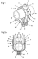
- FIG. 1 shows a sensor attachment 1 in three-dimensional representation. This consists of a sensor 4, which is embedded in a socket 5.
- a bracket 7 is used, which surrounds the tube 2 U-shaped and received with the base 5 via a grid a mechanical connection.
- a container 8 is used at the base 73 of the bracket 7 , which surrounds the tube 2 U-shaped and received with the base 5 via a grid a mechanical connection.
- a container 8 with a cover 9 on the outside.
- a Spring element 10 which can be fixed in the cover 9 via detents 11 and which exerts a contact pressure on the tube 2.
- the spring element 10 serves to compensate for the steps of the screening of the bracket attachment, as well as a material fatigue and a temperature-induced expansion tolerance.
- the bracket 7, which brings the tube 2 with the sensor 4 into contact is designed so that a right arm 72 and a left arm 71 of the bracket 7, the tube 2 laterally and form a mechanical connection with the base 5.
- the bracket 7 is formed approximately half-round in the region of the base 73, so that a pre-centering of the tube 2 in the sensor attachment 1 takes place.
- 73 rows of teeth 12 are attached to the inner sides of the right arm 72 and the left arm.
- a guide groove fourteenth On the outer side of the base 5 in the area of the counter teeth 13, there is a guide web 15, which fits the guide groove 14 in a form-fitting manner.
- the guide web 15 is designed such that it can slide flush into the guide groove 14.
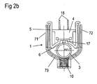
- FIG. 2a shows a sensor attachment 1 in a side view.
- the surface of the base 5, which serves to receive the tube 2, designed in accordance with a partially circular cylinder 16, at its lowest point, a channel 17 is located.
- the channel 17 has a Width which is twice as large as the depth of the channel 17.
- the half width of the channel 17 corresponds approximately to the diameter of the sensor 6th
- the sensor 6 of the sensor 4 is located in the middle of the channel 17, so that the sensor 6 of the sensor 4 so far protrudes from the base 5 that it extends beyond the edge of the continued radius of the semicircular cylinder 16.
- On the opposite side of the sensor are preferably two contact pins 18 for electrical connection of the sensor. 4
- FIG. 2b shows a sensor attachment 1 after FIG. 2a in which the tube 3 has a smaller diameter than in FIG. 2a ,
Landscapes
- Physics & Mathematics (AREA)
- General Physics & Mathematics (AREA)
- Engineering & Computer Science (AREA)
- General Engineering & Computer Science (AREA)
- Mechanical Engineering (AREA)
- Measuring Temperature Or Quantity Of Heat (AREA)
- Measuring Fluid Pressure (AREA)
Claims (12)
- Dispositif de fixation d'un capteur sur un tuyau,- présentant un arceau (7) et un socle (5), qui sont raccordés mécaniquement l'un à l'autre,- avec un capteur (4) pour détecter une grandeur de mesure physique, lequel capteur se trouve dans le socle (5), et- avec un élément élastique (10) dans la région d'une base (73) de l'arceau,- l'arceau (7) présentant un premier bras (71) et un deuxième bras (72), qui sont raccordés l'un à l'autre par la base (73) de l'arceau (7),- l'arceau (7) étant raccordé au socle (5) par une fixation variable, et- le premier bras (71) et le deuxième bras (72) présentant des rangées de dents (9) et des dents conjuguées (13) se trouvant sur les côtés étroits opposés du socle (5), lesquelles dents conjuguées peuvent s'engrener avec les rangées de dents (9) des bras (71, 72).
- Dispositif selon la revendication 1, dans lequel l'élément élastique (10) est réalisé sous forme de ressort.
- Dispositif selon l'une quelconque des revendications précédentes, dans lequel le capteur (4) comprend un capteur de température.
- Dispositif selon l'une quelconque des revendications précédentes, dans lequel les rangées de dents (9) et les dents conjuguées (13) peuvent être engrenées les unes avec les autres de manière graduelle.
- Dispositif selon l'une quelconque des revendications précédentes, dans lequel l'étrier (7) et le socle (5) présentent un dispositif qui empêche un glissement latéral mutuel.
- Dispositif selon l'une quelconque des revendications précédentes, dans lequel le premier bras (71) et/ou le deuxième bras (72) présentent au moins une rainure de guidage (11), et dans lequel le socle (4) présente, sur un côté étroit au moins une nervure de guidage (12), qui peut être guidée dans la rainure de guidage.
- Dispositif selon l'une quelconque des revendications précédentes, dans lequel la base (73) de l'arceau présente des transitions biseautées vers les bras (71, 72).
- Dispositif selon l'une quelconque des revendications précédentes, dans lequel l'arceau (7) présente, du côté extérieur de sa base (73), un récipient (8) pour recevoir l'élément élastique (10).
- Dispositif selon l'une quelconque des revendications précédentes, dans lequel le socle (5) est réalisé sous forme cylindrique partielle (16) concave sur sa surface du côté du tuyau.
- Dispositif selon la revendication 9, dans lequel le socle présente un canal (17) au sommet de la surface de forme cylindrique partielle.
- Dispositif selon la revendication 10, dans lequel un palpeur de mesure (6) du capteur (4) se trouve dans le canal (17), lequel pénètre dans l'espace intérieur qui est formé par la surface de forme cylindrique partielle (16) et est connecté de manière électriquement conductrice à des contacts.
- Dispositif selon l'une quelconque des revendications 9 à 11, dans lequel le rayon de la surface de forme cylindrique partielle (16) du socle (4) correspond au rayon du plus grand tuyau (2 ; 3) prévu pour le dispositif.
Applications Claiming Priority (1)
| Application Number | Priority Date | Filing Date | Title |
|---|---|---|---|
| DE102007023877A DE102007023877A1 (de) | 2007-05-23 | 2007-05-23 | Vorrichtung zur Befestigung eines Sensors an einem Rohr |
Publications (3)
| Publication Number | Publication Date |
|---|---|
| EP2000787A2 EP2000787A2 (fr) | 2008-12-10 |
| EP2000787A3 EP2000787A3 (fr) | 2011-03-16 |
| EP2000787B1 true EP2000787B1 (fr) | 2012-07-11 |
Family
ID=39870656
Family Applications (1)
| Application Number | Title | Priority Date | Filing Date |
|---|---|---|---|
| EP08009309A Active EP2000787B1 (fr) | 2007-05-23 | 2008-05-20 | Dispositif de fixation d'un capteur sur un tuyau |
Country Status (3)
| Country | Link |
|---|---|
| EP (1) | EP2000787B1 (fr) |
| DE (1) | DE102007023877A1 (fr) |
| ES (1) | ES2388006T3 (fr) |
Cited By (1)
| Publication number | Priority date | Publication date | Assignee | Title |
|---|---|---|---|---|
| KR102165938B1 (ko) * | 2019-07-11 | 2020-10-14 | 박재환 | 튜브 표면 부착용 가속도센서 브라켓 |
Families Citing this family (10)
| Publication number | Priority date | Publication date | Assignee | Title |
|---|---|---|---|---|
| DE102009018594B4 (de) | 2009-04-20 | 2020-06-04 | Ifm Electronic Gmbh | Befestigungsvorrichtung für einen Sensor |
| CN102768021B (zh) * | 2012-08-01 | 2014-11-26 | 安徽工业大学 | 一种接触式圆柱体直径测量装置 |
| DE102015009618B4 (de) * | 2015-07-29 | 2017-04-13 | Testo SE & Co. KGaA | Haltevorrichtung und Verwendung eines Kodierelements |
| WO2017207620A1 (fr) * | 2016-05-31 | 2017-12-07 | Fresenius Kabi Austria Gmbh | Procédé de désinfection d'un système de conduites tubulaires et appareil de mesure permettant de confirmer une désinfection effectuée sur site |
| DE102016122798A1 (de) * | 2016-11-25 | 2018-05-30 | Fabian Nieberding | Schelle für das Festlegen von Rohren oder Kabeln |
| GB2567664B (en) * | 2017-10-19 | 2020-05-06 | Centrica Hive Ltd | Fluid conduit gripping means |
| CN107655508B (zh) * | 2017-10-28 | 2019-10-18 | 倡创(上海)咨询管理事务所 | 一种建筑施工领域的管材检测用固定设备 |
| RU196768U1 (ru) * | 2019-09-16 | 2020-03-16 | Общество с ограниченной ответственностью Научно-производственная фирма "Сосны" | Скоба измерительная |
| DE102022200354B3 (de) | 2022-01-14 | 2023-04-20 | Siemens Aktiengesellschaft | Selbstüberwachter Sensor, der als nichtinvasive Temperaturmessvorrichtung ausgebildet ist und zu einem Überwachen seiner Montage durch ein Erfassen einer Druckkraft ausgebildet ist und Computerprogrammprodukt |
| CN117072952A (zh) * | 2023-10-12 | 2023-11-17 | 四川鑫业纸业有限公司 | 外接式温度检测组件 |
Family Cites Families (6)
| Publication number | Priority date | Publication date | Assignee | Title |
|---|---|---|---|---|
| US2752411A (en) * | 1956-06-26 | walter | ||
| US2302640A (en) * | 1940-12-23 | 1942-11-17 | Fedders Mfg Co Inc | Refrigeration thermometer |
| FR2638522A1 (fr) * | 1988-11-03 | 1990-05-04 | Jaeger Regulation | Systeme thermostatique pour regulation de temperature |
| DK108696A (da) * | 1996-10-03 | 1998-04-04 | Gemina Termix Productions A S | Anordning til montering af temperaturmålers følerelement i termisk kontakt med rør og anvendelse af sådan anordning |
| US7377472B2 (en) * | 2002-12-16 | 2008-05-27 | Securus, Inc. | Pipe and cable holder |
| DE10358778B4 (de) | 2003-01-15 | 2014-04-24 | Behr Gmbh & Co. Kg | Anordnung zur Temperaturmessung und Temperatursensor |
-
2007
- 2007-05-23 DE DE102007023877A patent/DE102007023877A1/de not_active Ceased
-
2008
- 2008-05-20 ES ES08009309T patent/ES2388006T3/es active Active
- 2008-05-20 EP EP08009309A patent/EP2000787B1/fr active Active
Cited By (1)
| Publication number | Priority date | Publication date | Assignee | Title |
|---|---|---|---|---|
| KR102165938B1 (ko) * | 2019-07-11 | 2020-10-14 | 박재환 | 튜브 표면 부착용 가속도센서 브라켓 |
Also Published As
| Publication number | Publication date |
|---|---|
| EP2000787A3 (fr) | 2011-03-16 |
| ES2388006T3 (es) | 2012-10-05 |
| EP2000787A2 (fr) | 2008-12-10 |
| DE102007023877A1 (de) | 2008-11-27 |
Similar Documents
| Publication | Publication Date | Title |
|---|---|---|
| EP2000787B1 (fr) | Dispositif de fixation d'un capteur sur un tuyau | |
| EP1169202B1 (fr) | Dispositif pour mesurer une pression de fluide | |
| EP2038625B2 (fr) | Dispositif de mesure de température | |
| DE102010015813A1 (de) | Sensoranordnung für ein kalorimetrisches Massedurchflussmessgerät | |
| DE102007011546A1 (de) | Fluidzähler | |
| EP2553413B1 (fr) | Capteur de mesure présentant un boîtier | |
| DE202009012292U1 (de) | Temperaturfühler mit Prüfkanal | |
| DE102013208785A1 (de) | Messgerät, insbesondere für die Prozessmesstechnik, mit einer zylinderförmigen Sensorspitze | |
| DE10232315B4 (de) | Kombinierter Temperatur- und Druckfühler und Verfahren zur Ermittlung von physikalischen Kenngrößen | |
| DE102006033467B4 (de) | Druckerfassungsvorrichtung | |
| DE102010012823B4 (de) | Druckmittler mit Temperatursensor | |
| EP2778600A1 (fr) | Unité de mesure, dispositif et procédé de mesure d'évidement et/ou d'espacements | |
| DE19512111A1 (de) | Wärmeübergangskontroll- und/oder -meßgerät | |
| DE102018129357A1 (de) | Messsonde zur Bestimmung oder Überwachung einer physikalischen oder chemischen Prozessgröße eines Mediums | |
| DE102013114140A1 (de) | Messfühlergehäuse und Messfühleranordnung mit einem Messfühlergehäuse | |
| DE2706326A1 (de) | Steckverbindung fuer ein tauchthermoelement | |
| DE102012206647A1 (de) | Messgerät für die Prozessmesstechnik mit einer zylinderförmigen Sensorspitze | |
| KR101755142B1 (ko) | 금속화된 변형가능한 기판들에서의 로우 포스 전기 접촉부 | |
| DE102019216460A1 (de) | Temperaturfühler mit Prüfkanal | |
| EP1882179B1 (fr) | Capteur a grille | |
| DE102014011724B3 (de) | Schutzrohrvorrichtung zum Schutz eines Temperatursensors vor Kontakt mit einem Fluid | |
| DE102014001640B4 (de) | Druck- und Temperatursensor-Element | |
| AT516331B1 (de) | Halterung für Sensoren | |
| DE102023108929A1 (de) | Temperatursensor und Durchflussmessgerät | |
| DE10124552B4 (de) | Vorrichtung zum Messen von geometrischen Abmessungen eines Werkstücks, insbesondere Meßschieber oder Schieblehre |
Legal Events
| Date | Code | Title | Description |
|---|---|---|---|
| PUAI | Public reference made under article 153(3) epc to a published international application that has entered the european phase |
Free format text: ORIGINAL CODE: 0009012 |
|
| AK | Designated contracting states |
Kind code of ref document: A2 Designated state(s): AT BE BG CH CY CZ DE DK EE ES FI FR GB GR HR HU IE IS IT LI LT LU LV MC MT NL NO PL PT RO SE SI SK TR |
|
| AX | Request for extension of the european patent |
Extension state: AL BA MK RS |
|
| PUAL | Search report despatched |
Free format text: ORIGINAL CODE: 0009013 |
|
| AK | Designated contracting states |
Kind code of ref document: A3 Designated state(s): AT BE BG CH CY CZ DE DK EE ES FI FR GB GR HR HU IE IS IT LI LT LU LV MC MT NL NO PL PT RO SE SI SK TR |
|
| AX | Request for extension of the european patent |
Extension state: AL BA MK RS |
|
| RIC1 | Information provided on ipc code assigned before grant |
Ipc: G01D 11/30 20060101ALI20110208BHEP Ipc: G01K 1/14 20060101AFI20081031BHEP |
|
| 17P | Request for examination filed |
Effective date: 20110916 |
|
| RIC1 | Information provided on ipc code assigned before grant |
Ipc: G01D 11/30 20060101ALI20111007BHEP Ipc: G01K 1/14 20060101AFI20111007BHEP |
|
| AKX | Designation fees paid |
Designated state(s): AT BE BG CH CY CZ DE DK EE ES FI FR GB GR HR HU IE IS IT LI LT LU LV MC MT NL NO PL PT RO SE SI SK TR |
|
| GRAP | Despatch of communication of intention to grant a patent |
Free format text: ORIGINAL CODE: EPIDOSNIGR1 |
|
| GRAS | Grant fee paid |
Free format text: ORIGINAL CODE: EPIDOSNIGR3 |
|
| GRAA | (expected) grant |
Free format text: ORIGINAL CODE: 0009210 |
|
| AK | Designated contracting states |
Kind code of ref document: B1 Designated state(s): AT BE BG CH CY CZ DE DK EE ES FI FR GB GR HR HU IE IS IT LI LT LU LV MC MT NL NO PL PT RO SE SI SK TR |
|
| REG | Reference to a national code |
Ref country code: GB Ref legal event code: FG4D Free format text: NOT ENGLISH |
|
| REG | Reference to a national code |
Ref country code: CH Ref legal event code: EP |
|
| REG | Reference to a national code |
Ref country code: AT Ref legal event code: REF Ref document number: 566372 Country of ref document: AT Kind code of ref document: T Effective date: 20120715 |
|
| REG | Reference to a national code |
Ref country code: IE Ref legal event code: FG4D Free format text: LANGUAGE OF EP DOCUMENT: GERMAN |
|
| REG | Reference to a national code |
Ref country code: DE Ref legal event code: R096 Ref document number: 502008007672 Country of ref document: DE Effective date: 20120906 |
|
| REG | Reference to a national code |
Ref country code: ES Ref legal event code: FG2A Ref document number: 2388006 Country of ref document: ES Kind code of ref document: T3 Effective date: 20121005 |
|
| REG | Reference to a national code |
Ref country code: NL Ref legal event code: VDEP Effective date: 20120711 |
|
| REG | Reference to a national code |
Ref country code: LT Ref legal event code: MG4D Effective date: 20120711 |
|
| PG25 | Lapsed in a contracting state [announced via postgrant information from national office to epo] |
Ref country code: NO Free format text: LAPSE BECAUSE OF FAILURE TO SUBMIT A TRANSLATION OF THE DESCRIPTION OR TO PAY THE FEE WITHIN THE PRESCRIBED TIME-LIMIT Effective date: 20121011 Ref country code: FI Free format text: LAPSE BECAUSE OF FAILURE TO SUBMIT A TRANSLATION OF THE DESCRIPTION OR TO PAY THE FEE WITHIN THE PRESCRIBED TIME-LIMIT Effective date: 20120711 Ref country code: CY Free format text: LAPSE BECAUSE OF FAILURE TO SUBMIT A TRANSLATION OF THE DESCRIPTION OR TO PAY THE FEE WITHIN THE PRESCRIBED TIME-LIMIT Effective date: 20120711 Ref country code: IS Free format text: LAPSE BECAUSE OF FAILURE TO SUBMIT A TRANSLATION OF THE DESCRIPTION OR TO PAY THE FEE WITHIN THE PRESCRIBED TIME-LIMIT Effective date: 20121111 Ref country code: HR Free format text: LAPSE BECAUSE OF FAILURE TO SUBMIT A TRANSLATION OF THE DESCRIPTION OR TO PAY THE FEE WITHIN THE PRESCRIBED TIME-LIMIT Effective date: 20120711 Ref country code: LT Free format text: LAPSE BECAUSE OF FAILURE TO SUBMIT A TRANSLATION OF THE DESCRIPTION OR TO PAY THE FEE WITHIN THE PRESCRIBED TIME-LIMIT Effective date: 20120711 |
|
| PG25 | Lapsed in a contracting state [announced via postgrant information from national office to epo] |
Ref country code: SE Free format text: LAPSE BECAUSE OF FAILURE TO SUBMIT A TRANSLATION OF THE DESCRIPTION OR TO PAY THE FEE WITHIN THE PRESCRIBED TIME-LIMIT Effective date: 20120711 Ref country code: PT Free format text: LAPSE BECAUSE OF FAILURE TO SUBMIT A TRANSLATION OF THE DESCRIPTION OR TO PAY THE FEE WITHIN THE PRESCRIBED TIME-LIMIT Effective date: 20121112 Ref country code: LV Free format text: LAPSE BECAUSE OF FAILURE TO SUBMIT A TRANSLATION OF THE DESCRIPTION OR TO PAY THE FEE WITHIN THE PRESCRIBED TIME-LIMIT Effective date: 20120711 Ref country code: PL Free format text: LAPSE BECAUSE OF FAILURE TO SUBMIT A TRANSLATION OF THE DESCRIPTION OR TO PAY THE FEE WITHIN THE PRESCRIBED TIME-LIMIT Effective date: 20120711 Ref country code: GR Free format text: LAPSE BECAUSE OF FAILURE TO SUBMIT A TRANSLATION OF THE DESCRIPTION OR TO PAY THE FEE WITHIN THE PRESCRIBED TIME-LIMIT Effective date: 20121012 Ref country code: SI Free format text: LAPSE BECAUSE OF FAILURE TO SUBMIT A TRANSLATION OF THE DESCRIPTION OR TO PAY THE FEE WITHIN THE PRESCRIBED TIME-LIMIT Effective date: 20120711 |
|
| PG25 | Lapsed in a contracting state [announced via postgrant information from national office to epo] |
Ref country code: NL Free format text: LAPSE BECAUSE OF FAILURE TO SUBMIT A TRANSLATION OF THE DESCRIPTION OR TO PAY THE FEE WITHIN THE PRESCRIBED TIME-LIMIT Effective date: 20120711 |
|
| PG25 | Lapsed in a contracting state [announced via postgrant information from national office to epo] |
Ref country code: CZ Free format text: LAPSE BECAUSE OF FAILURE TO SUBMIT A TRANSLATION OF THE DESCRIPTION OR TO PAY THE FEE WITHIN THE PRESCRIBED TIME-LIMIT Effective date: 20120711 Ref country code: RO Free format text: LAPSE BECAUSE OF FAILURE TO SUBMIT A TRANSLATION OF THE DESCRIPTION OR TO PAY THE FEE WITHIN THE PRESCRIBED TIME-LIMIT Effective date: 20120711 Ref country code: EE Free format text: LAPSE BECAUSE OF FAILURE TO SUBMIT A TRANSLATION OF THE DESCRIPTION OR TO PAY THE FEE WITHIN THE PRESCRIBED TIME-LIMIT Effective date: 20120711 Ref country code: DK Free format text: LAPSE BECAUSE OF FAILURE TO SUBMIT A TRANSLATION OF THE DESCRIPTION OR TO PAY THE FEE WITHIN THE PRESCRIBED TIME-LIMIT Effective date: 20120711 |
|
| PLBE | No opposition filed within time limit |
Free format text: ORIGINAL CODE: 0009261 |
|
| STAA | Information on the status of an ep patent application or granted ep patent |
Free format text: STATUS: NO OPPOSITION FILED WITHIN TIME LIMIT |
|
| PG25 | Lapsed in a contracting state [announced via postgrant information from national office to epo] |
Ref country code: SK Free format text: LAPSE BECAUSE OF FAILURE TO SUBMIT A TRANSLATION OF THE DESCRIPTION OR TO PAY THE FEE WITHIN THE PRESCRIBED TIME-LIMIT Effective date: 20120711 |
|
| 26N | No opposition filed |
Effective date: 20130412 |
|
| PG25 | Lapsed in a contracting state [announced via postgrant information from national office to epo] |
Ref country code: BG Free format text: LAPSE BECAUSE OF FAILURE TO SUBMIT A TRANSLATION OF THE DESCRIPTION OR TO PAY THE FEE WITHIN THE PRESCRIBED TIME-LIMIT Effective date: 20121011 |
|
| REG | Reference to a national code |
Ref country code: DE Ref legal event code: R097 Ref document number: 502008007672 Country of ref document: DE Effective date: 20130412 |
|
| BERE | Be: lapsed |
Owner name: EPCOS A.G. Effective date: 20130531 |
|
| PG25 | Lapsed in a contracting state [announced via postgrant information from national office to epo] |
Ref country code: MC Free format text: LAPSE BECAUSE OF FAILURE TO SUBMIT A TRANSLATION OF THE DESCRIPTION OR TO PAY THE FEE WITHIN THE PRESCRIBED TIME-LIMIT Effective date: 20120711 |
|
| REG | Reference to a national code |
Ref country code: CH Ref legal event code: PL |
|
| PG25 | Lapsed in a contracting state [announced via postgrant information from national office to epo] |
Ref country code: LI Free format text: LAPSE BECAUSE OF NON-PAYMENT OF DUE FEES Effective date: 20130531 Ref country code: CH Free format text: LAPSE BECAUSE OF NON-PAYMENT OF DUE FEES Effective date: 20130531 |
|
| REG | Reference to a national code |
Ref country code: IE Ref legal event code: MM4A |
|
| PG25 | Lapsed in a contracting state [announced via postgrant information from national office to epo] |
Ref country code: BE Free format text: LAPSE BECAUSE OF NON-PAYMENT OF DUE FEES Effective date: 20130531 |
|
| PG25 | Lapsed in a contracting state [announced via postgrant information from national office to epo] |
Ref country code: IE Free format text: LAPSE BECAUSE OF NON-PAYMENT OF DUE FEES Effective date: 20130520 |
|
| REG | Reference to a national code |
Ref country code: AT Ref legal event code: MM01 Ref document number: 566372 Country of ref document: AT Kind code of ref document: T Effective date: 20130520 |
|
| PG25 | Lapsed in a contracting state [announced via postgrant information from national office to epo] |
Ref country code: AT Free format text: LAPSE BECAUSE OF NON-PAYMENT OF DUE FEES Effective date: 20130520 |
|
| PG25 | Lapsed in a contracting state [announced via postgrant information from national office to epo] |
Ref country code: MT Free format text: LAPSE BECAUSE OF FAILURE TO SUBMIT A TRANSLATION OF THE DESCRIPTION OR TO PAY THE FEE WITHIN THE PRESCRIBED TIME-LIMIT Effective date: 20120711 |
|
| PG25 | Lapsed in a contracting state [announced via postgrant information from national office to epo] |
Ref country code: LU Free format text: LAPSE BECAUSE OF NON-PAYMENT OF DUE FEES Effective date: 20130520 Ref country code: HU Free format text: LAPSE BECAUSE OF FAILURE TO SUBMIT A TRANSLATION OF THE DESCRIPTION OR TO PAY THE FEE WITHIN THE PRESCRIBED TIME-LIMIT; INVALID AB INITIO Effective date: 20080520 |
|
| PGFP | Annual fee paid to national office [announced via postgrant information from national office to epo] |
Ref country code: TR Payment date: 20150508 Year of fee payment: 8 |
|
| REG | Reference to a national code |
Ref country code: FR Ref legal event code: PLFP Year of fee payment: 9 |
|
| REG | Reference to a national code |
Ref country code: FR Ref legal event code: PLFP Year of fee payment: 10 |
|
| REG | Reference to a national code |
Ref country code: FR Ref legal event code: PLFP Year of fee payment: 11 |
|
| REG | Reference to a national code |
Ref country code: DE Ref legal event code: R082 Ref document number: 502008007672 Country of ref document: DE Representative=s name: EPPING HERMANN FISCHER PATENTANWALTSGESELLSCHA, DE Ref country code: DE Ref legal event code: R081 Ref document number: 502008007672 Country of ref document: DE Owner name: TDK ELECTRONICS AG, DE Free format text: FORMER OWNER: EPCOS AG, 81669 MUENCHEN, DE |
|
| PGFP | Annual fee paid to national office [announced via postgrant information from national office to epo] |
Ref country code: BE Payment date: 20190627 Year of fee payment: 11 Ref country code: ES Payment date: 20190619 Year of fee payment: 12 |
|
| PGFP | Annual fee paid to national office [announced via postgrant information from national office to epo] |
Ref country code: FR Payment date: 20190521 Year of fee payment: 12 |
|
| PGFP | Annual fee paid to national office [announced via postgrant information from national office to epo] |
Ref country code: GB Payment date: 20190523 Year of fee payment: 12 |
|
| GBPC | Gb: european patent ceased through non-payment of renewal fee |
Effective date: 20200520 |
|
| PG25 | Lapsed in a contracting state [announced via postgrant information from national office to epo] |
Ref country code: GB Free format text: LAPSE BECAUSE OF NON-PAYMENT OF DUE FEES Effective date: 20200520 Ref country code: FR Free format text: LAPSE BECAUSE OF NON-PAYMENT OF DUE FEES Effective date: 20200531 |
|
| REG | Reference to a national code |
Ref country code: ES Ref legal event code: FD2A Effective date: 20211004 |
|
| PG25 | Lapsed in a contracting state [announced via postgrant information from national office to epo] |
Ref country code: IT Free format text: LAPSE BECAUSE OF NON-PAYMENT OF DUE FEES Effective date: 20200520 |
|
| PG25 | Lapsed in a contracting state [announced via postgrant information from national office to epo] |
Ref country code: ES Free format text: LAPSE BECAUSE OF NON-PAYMENT OF DUE FEES Effective date: 20200521 |
|
| PG25 | Lapsed in a contracting state [announced via postgrant information from national office to epo] |
Ref country code: TR Free format text: LAPSE BECAUSE OF NON-PAYMENT OF DUE FEES Effective date: 20160520 |
|
| P01 | Opt-out of the competence of the unified patent court (upc) registered |
Effective date: 20230521 |
|
| PGFP | Annual fee paid to national office [announced via postgrant information from national office to epo] |
Ref country code: DE Payment date: 20240522 Year of fee payment: 17 |