EP2000787B1 - Device for attaching a sensor to a tube - Google Patents
Device for attaching a sensor to a tube Download PDFInfo
- Publication number
- EP2000787B1 EP2000787B1 EP08009309A EP08009309A EP2000787B1 EP 2000787 B1 EP2000787 B1 EP 2000787B1 EP 08009309 A EP08009309 A EP 08009309A EP 08009309 A EP08009309 A EP 08009309A EP 2000787 B1 EP2000787 B1 EP 2000787B1
- Authority
- EP
- European Patent Office
- Prior art keywords
- sensor
- bracket
- mount
- base
- teeth
- Prior art date
- Legal status (The legal status is an assumption and is not a legal conclusion. Google has not performed a legal analysis and makes no representation as to the accuracy of the status listed.)
- Active
Links
Images
Classifications
-
- G—PHYSICS
- G01—MEASURING; TESTING
- G01K—MEASURING TEMPERATURE; MEASURING QUANTITY OF HEAT; THERMALLY-SENSITIVE ELEMENTS NOT OTHERWISE PROVIDED FOR
- G01K1/00—Details of thermometers not specially adapted for particular types of thermometer
- G01K1/14—Supports; Fastening devices; Arrangements for mounting thermometers in particular locations
- G01K1/143—Supports; Fastening devices; Arrangements for mounting thermometers in particular locations for measuring surface temperatures
-
- F—MECHANICAL ENGINEERING; LIGHTING; HEATING; WEAPONS; BLASTING
- F16—ENGINEERING ELEMENTS AND UNITS; GENERAL MEASURES FOR PRODUCING AND MAINTAINING EFFECTIVE FUNCTIONING OF MACHINES OR INSTALLATIONS; THERMAL INSULATION IN GENERAL
- F16L—PIPES; JOINTS OR FITTINGS FOR PIPES; SUPPORTS FOR PIPES, CABLES OR PROTECTIVE TUBING; MEANS FOR THERMAL INSULATION IN GENERAL
- F16L3/00—Supports for pipes, cables or protective tubing, e.g. hangers, holders, clamps, cleats, clips, brackets
- F16L3/08—Supports for pipes, cables or protective tubing, e.g. hangers, holders, clamps, cleats, clips, brackets substantially surrounding the pipe, cable or protective tubing
- F16L3/10—Supports for pipes, cables or protective tubing, e.g. hangers, holders, clamps, cleats, clips, brackets substantially surrounding the pipe, cable or protective tubing divided, i.e. with two or more members engaging the pipe, cable or protective tubing
- F16L3/1008—Supports for pipes, cables or protective tubing, e.g. hangers, holders, clamps, cleats, clips, brackets substantially surrounding the pipe, cable or protective tubing divided, i.e. with two or more members engaging the pipe, cable or protective tubing with two members engaging the pipe, cable or tubing, both being made of thin band material completely surrounding the pipe
- F16L3/1025—Supports for pipes, cables or protective tubing, e.g. hangers, holders, clamps, cleats, clips, brackets substantially surrounding the pipe, cable or protective tubing divided, i.e. with two or more members engaging the pipe, cable or protective tubing with two members engaging the pipe, cable or tubing, both being made of thin band material completely surrounding the pipe the members being joined by quick acting means
-
- G—PHYSICS
- G01—MEASURING; TESTING
- G01D—MEASURING NOT SPECIALLY ADAPTED FOR A SPECIFIC VARIABLE; ARRANGEMENTS FOR MEASURING TWO OR MORE VARIABLES NOT COVERED IN A SINGLE OTHER SUBCLASS; TARIFF METERING APPARATUS; MEASURING OR TESTING NOT OTHERWISE PROVIDED FOR
- G01D11/00—Component parts of measuring arrangements not specially adapted for a specific variable
- G01D11/30—Supports specially adapted for an instrument; Supports specially adapted for a set of instruments
Definitions
- a device which serves to receive and attach a sensor to pipes of different diameter.
- the publication FR 2 638 522 A1 describes a temperature measuring device with a sensor mounted on a support and in contact with a pipe whose temperature is to be measured.
- the temperature measuring device has a body, at the upper region of the sensor and the carrier are arranged and whose lower portion has a recess in which the tube can be arranged.
- the probe is pressed against the tube by means of a spring.
- the clamping device 10 for fixing a tube 22 to a carrier is described.
- the clamping device 10 has a base element 12, which is connected by means of two bracket arms 16 releasably connected to a fastening element 14.
- An object to be solved is to provide a sensor attachment that provides a mounting for a sensor on pipes with different pipe diameters.
- the sensor attachment comprises a base, in which a sensor for detecting physical quantities is integrated, and a bracket.
- the base and the bracket are mechanically connected.
- At the base of the stirrup is an elastic element.
- the elastic element comprises a spring made of steel, or of another material which is permanently elastically or elastically compressible.
- the sensor may be various types of sensors used to receive physical measurements. This is preferably a temperature sensor.
- a temperature sensor is provided which measures the surface temperature of a pipe to which the sensor is attached.
- the sensor attachment is preferably used to receive a sensor for measuring the temperature of a fluid.
- the fluid may be either a gaseous or a liquid medium.
- the sensor is not introduced into the container of the medium, but merely brought to the outer surface of the container. As a result, potential leaks in the media container, for example in a pipe in which the medium flows, can be avoided.
- the sensor assumes the temperature to be measured. Therefore, it is important that good thermal coupling between the probe and the DUT is ensured.
- the pipe In order for the pipe, whose surface temperature is to be measured, to come into contact with the sensor, the pipe is connected to the base via a bracket.
- base and bracket In order to produce a mechanical connection between base and bracket, these are preferably connected to each other by means of an adjustable attachment. As a result, the sensor attachment is not fixed to pipes with a specific diameter.
- detents and counter-pawls are used, whereby it is possible to connect the base and the bracket not only in a certain position with each other.
- the rows of teeth are preferably in the end region of the lateral arms.
- On the base are on the narrow sides designed according to the rows of teeth of the bracket designed Gegenberger conspiracyloisn.
- a step-like engagement of the bracket on the base is possible. Due to the step-like locking, it is possible to include tubes with different diameters in the sensor attachment.
- one or more guide grooves which are arranged in the longitudinal direction of the arms, are located on the bow arms.
- On two sides of the base are one or more guide webs, preferably in the area of the opposing teeth.
- the guide webs preferably run parallel to the guide grooves or perpendicular to the opposing teeth.
- Each guide web preferably has approximately the outer cross section, which corresponds to the inner cross section of the associated guide groove of the hanger arms, so that the guide web can be inserted into the guide groove.
- the guide grooves may also be located on the base and the guide webs on the bracket.
- the bracket is provided with insertion bevels in the area of the base between the bracket arms so that a smooth transition of the bracket geometry of the bracket cross-section to the arms can take place. This is preferably a kind of pre-centering of the tube, so that the tube rests centrally on the base, and so an optimal contact with the probe is ensured.
- the spring is preferably mounted in a container mounted on the outside of the stirrup such that part of the spring projects into the space formed by the arms of the stirrup.
- For attachment of the spring in the container preferably located on the inside of the outer cover of the container detents or other fastening devices.
- the container and the catches are not necessary.
- These elastic elements can be fixed by gluing or other types of fastening on the inside of the bracket.
- the sensor is arranged in a recess.
- the thermal decoupling between the protruding portion of the probe, which according to a preferred embodiment contains a temperature-sensitive element, and the hidden portion of the probe can be improved and thus provide for a more accurate temperature measurement.
- the top of the pedestal is preferably designed to correspond to a part-round cylinder.
- This partial cylindrical surface has at the apex a channel-shaped depression, which is preferably approximately twice as wide as it is deep. In the middle of this recess is an opening through which the sensor of the sensor is guided. The sensor protrudes a few millimeters beyond the extension of the radius of the part-round cylinder. This has the advantage that even at a tube, which has the maximum diameter specified for the sensor attachment, nor an insulating air layer between the partially circular cylinder surface and the surface of the fixed tube is present.
- the sensor to connect the sensor to a data acquisition device, in one embodiment, there are at least two metal pins on the outside of the socket that are electrically connected to the probe.
- the sensor attachment is designed such that the sensor attachment is defined by the region in which the detents are located on the stirrup arms and the region in which the counterstops are located on the base for a diameter region of the receivable tubes.
- the sensor attachment is designed to be suitable for tubes having an outer diameter of 12-17 mm. But there are others, too larger areas possible.
- the receiving area is limited only by the design of the areas of the detents and counter-latches.
- the pedestal is positioned on the tube so that the probe makes contact with the tube.
- the bracket is now pushed so far onto the base until the spring element gets in contact with the pipe and exerts a contact pressure on the pipe. In this position, the bracket is locked to the base via the detents in the next possible step position.
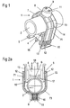
- FIG. 1 shows a sensor attachment 1 in three-dimensional representation. This consists of a sensor 4, which is embedded in a socket 5.
- a bracket 7 is used, which surrounds the tube 2 U-shaped and received with the base 5 via a grid a mechanical connection.
- a container 8 is used at the base 73 of the bracket 7 , which surrounds the tube 2 U-shaped and received with the base 5 via a grid a mechanical connection.
- a container 8 with a cover 9 on the outside.
- a Spring element 10 which can be fixed in the cover 9 via detents 11 and which exerts a contact pressure on the tube 2.
- the spring element 10 serves to compensate for the steps of the screening of the bracket attachment, as well as a material fatigue and a temperature-induced expansion tolerance.
- the bracket 7, which brings the tube 2 with the sensor 4 into contact is designed so that a right arm 72 and a left arm 71 of the bracket 7, the tube 2 laterally and form a mechanical connection with the base 5.
- the bracket 7 is formed approximately half-round in the region of the base 73, so that a pre-centering of the tube 2 in the sensor attachment 1 takes place.
- 73 rows of teeth 12 are attached to the inner sides of the right arm 72 and the left arm.
- a guide groove fourteenth On the outer side of the base 5 in the area of the counter teeth 13, there is a guide web 15, which fits the guide groove 14 in a form-fitting manner.
- the guide web 15 is designed such that it can slide flush into the guide groove 14.
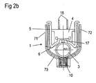
- FIG. 2a shows a sensor attachment 1 in a side view.
- the surface of the base 5, which serves to receive the tube 2, designed in accordance with a partially circular cylinder 16, at its lowest point, a channel 17 is located.
- the channel 17 has a Width which is twice as large as the depth of the channel 17.
- the half width of the channel 17 corresponds approximately to the diameter of the sensor 6th
- the sensor 6 of the sensor 4 is located in the middle of the channel 17, so that the sensor 6 of the sensor 4 so far protrudes from the base 5 that it extends beyond the edge of the continued radius of the semicircular cylinder 16.
- On the opposite side of the sensor are preferably two contact pins 18 for electrical connection of the sensor. 4
- FIG. 2b shows a sensor attachment 1 after FIG. 2a in which the tube 3 has a smaller diameter than in FIG. 2a ,
Description
Es wird eine Vorrichtung beschrieben, die für die Aufnahme und Befestigung eines Sensors an Rohren mit unterschiedlichem Durchmesser dient.A device is described which serves to receive and attach a sensor to pipes of different diameter.
Aus der Druckschrift
Die Druckschrift
In der Druckschrift
Eine zu lösende Aufgabe besteht darin, eine Sensorbefestigung anzugeben, die eine Befestigung für einen Sensor an Rohren mit unterschiedlichem Rohrdurchmesser bereitstellt.An object to be solved is to provide a sensor attachment that provides a mounting for a sensor on pipes with different pipe diameters.
Diese Aufgabe wird durch eine Vorrichtung mit den Merkmalen des unabhängigen Patentanspruchs 1 gelöst.This object is achieved by a device having the features of
Die Sensorbefestigung umfasst einen Sockel, in den ein Sensor zur Erfassung von physikalischen Messgrößen integriert ist, und einen Bügel. Der Sockel und der Bügel sind mechanisch miteinander verbunden. An der Basis des Bügels befindet sich ein elastisches Element.The sensor attachment comprises a base, in which a sensor for detecting physical quantities is integrated, and a bracket. The base and the bracket are mechanically connected. At the base of the stirrup is an elastic element.
Vorteilhaft umfasst das elastische Element eine Feder aus Stahl, oder aus einem anderen Werkstoff, der dauerhaft elastisch oder elastisch komprimierbar ist.Advantageously, the elastic element comprises a spring made of steel, or of another material which is permanently elastically or elastically compressible.
Bei dem Sensor kann es sich um verschiedene Arten von Sensoren handeln, die zur Aufnahme von physikalischen Messgrößen dienen. Vorzugsweise handelt es sich hierbei um einen Temperatursensor. Insbesondere ist ein Temperatursensor vorgesehen, der die Oberflächentemperatur eines Rohres misst, an dem der Sensor befestigt ist.The sensor may be various types of sensors used to receive physical measurements. This is preferably a temperature sensor. In particular, a temperature sensor is provided which measures the surface temperature of a pipe to which the sensor is attached.
Die Sensorbefestigung wird vorzugsweise zur Aufnahme eines Sensors zur Messung der Temperatur eines Fluids verwendet. Das Fluid kann dabei entweder ein gasförmiges oder ein flüssiges Medium sein. Zur Messung der Temperatur des Fluids beziehungsweise des Mediums wird der Sensor dabei nicht in den Behälter des Mediums eingeführt, sondern lediglich an die Außenfläche des Behälters herangeführt. Dadurch können potentielle Leckstellen im Medienbehälter, beispielsweise in einem Rohr, in dem das Medium fließt, vermieden werden.The sensor attachment is preferably used to receive a sensor for measuring the temperature of a fluid. The fluid may be either a gaseous or a liquid medium. To measure the temperature of the fluid or of the medium, the sensor is not introduced into the container of the medium, but merely brought to the outer surface of the container. As a result, potential leaks in the media container, for example in a pipe in which the medium flows, can be avoided.
Um zu einer möglichst exakten Temperaturmessung zu gelangen, ist es erstrebenswert, dass der Messfühler die zu messende Temperatur annimmt. Daher ist es wichtig, dass eine gute thermische Kopplung zwischen dem Messfühler und dem Messobjekt sichergestellt ist.In order to achieve the most accurate temperature measurement, it is desirable that the sensor assumes the temperature to be measured. Therefore, it is important that good thermal coupling between the probe and the DUT is ensured.
Damit das Rohr, dessen Oberflächentemperatur gemessen werden soll, Kontakt zu dem Sensor bekommt, ist das Rohr über einen Bügel mit dem Sockel verbunden.In order for the pipe, whose surface temperature is to be measured, to come into contact with the sensor, the pipe is connected to the base via a bracket.
Um eine mechanische Verbindung zwischen Sockel und Bügel herzustellen, werden diese vorzugsweise mittels einer verstellbaren Befestigung miteinander verbunden. Dadurch ist die Sensorbefestigung nicht auf Rohre mit einem bestimmten Durchmesser festgelegt. Bei der Erfindung werden Rasten und Gegenrasten verwendet, wodurch es möglich ist, den Sockel und den Bügel nicht nur in einer bestimmten Stellung miteinander zu verbinden.In order to produce a mechanical connection between base and bracket, these are preferably connected to each other by means of an adjustable attachment. As a result, the sensor attachment is not fixed to pipes with a specific diameter. In the invention, detents and counter-pawls are used, whereby it is possible to connect the base and the bracket not only in a certain position with each other.
Dafür befinden sich an mindestens einer Seite der Arme des Bügels Zahnreihen. Die Zahnreihen befinden sich vorzugsweise im Endbereich der seitlichen Arme. Am Sockel befinden sich an den schmalen Seiten entsprechend den Zahnreihen des Bügels gestaltete Gegenzahnreihen. Durch diese Zahn- und Gegenzahnreihen ist ein stufenartiges Einrasten des Bügels auf den Sockel möglich. Durch das stufenartige Einrasten ist es möglich, Rohre mit unterschiedlichem Durchmesser in die Sensorbefestigung aufzunehmen.For this there are at least one side of the arms of the bracket rows of teeth. The rows of teeth are preferably in the end region of the lateral arms. On the base are on the narrow sides designed according to the rows of teeth of the bracket designed Gegenzahnreihen. By these teeth and Gegenzahnreihen a step-like engagement of the bracket on the base is possible. Due to the step-like locking, it is possible to include tubes with different diameters in the sensor attachment.
Damit der eingerastete Bügel nicht seitlich vom Sockel abrutschen kann, befindet sich am Bügel eine Vorrichtung, die das Abrutschen verhindert. In einer bevorzugten Ausführungsform befinden sich an den Bügelarmen eine oder mehrere Führungsnuten, die in Längsrichtung der Arme angeordnet sind. Auf zwei Seiten des Sockels befinden sich ein oder mehrere Führungsstege, vorzugsweise in dem Bereich der Gegenzähne. Die Führungsstege verlaufen vorzugsweise parallel zu den Führungsnuten bzw. senkrecht zu den Gegenzähnen. Jeder Führungssteg weist vorzugsweise in etwa den Außenquerschnitt auf, der dem Innenquerschnitt der zugeordneten Führungsnut der Bügelarme entspricht, so dass der Führungssteg in die Führungsnut eingeführt werden kann. Alternativ können sich die Führungsnuten auch an dem Sockel und die Führungsstege an dem Bügel befinden.So that the latched bracket can not slip sideways from the base, located on the bracket, a device that prevents slipping. In a preferred embodiment, one or more guide grooves, which are arranged in the longitudinal direction of the arms, are located on the bow arms. On two sides of the base are one or more guide webs, preferably in the area of the opposing teeth. The guide webs preferably run parallel to the guide grooves or perpendicular to the opposing teeth. Each guide web preferably has approximately the outer cross section, which corresponds to the inner cross section of the associated guide groove of the hanger arms, so that the guide web can be inserted into the guide groove. Alternatively, the guide grooves may also be located on the base and the guide webs on the bracket.
Damit das Rohr einen optimalen Kontakt zu dem Sensor bekommt, ist der Bügel in einer Ausführungsform in dem Bereich der Basis zwischen den Bügelarmen mit Einführungsschrägen versehen, so dass ein fließender Übergang der Bügelgeometrie des Bügelquerschnitts zu den Armen hin erfolgen kann. Dies dient vorzugsweise einer Art von Vorzentrierung des Rohres, so dass das Rohr mittig auf dem Sockel aufliegt, und so ein optimaler Kontakt zu dem Messfühler gewährleistet ist.In order for the tube to have optimum contact with the sensor, in one embodiment, the bracket is provided with insertion bevels in the area of the base between the bracket arms so that a smooth transition of the bracket geometry of the bracket cross-section to the arms can take place. This is preferably a kind of pre-centering of the tube, so that the tube rests centrally on the base, and so an optimal contact with the probe is ensured.
Die Feder ist vorzugsweise so in einem an der Außenseite des Bügels angebrachten Behälter befestigt, dass ein Teil der Feder in den Raum ragt, der durch die Arme des Bügels gebildet wird. Zur Befestigung der Feder in dem Behälter, befinden sich auf der Innenseite der Außenabdeckung des Behälters vorzugsweise Rasten oder anderweitige Befestigungsvorrichtungen.The spring is preferably mounted in a container mounted on the outside of the stirrup such that part of the spring projects into the space formed by the arms of the stirrup. For attachment of the spring in the container, preferably located on the inside of the outer cover of the container detents or other fastening devices.
Bei der Verwendung von anderen elastischen Werkstoffen sind der Behälter und die Rasten nicht notwendig. Diese elastischen Elemente können durch Kleben oder andere Befestigungsarten auf der Innenseite des Bügels fixiert werden.When using other elastic materials, the container and the catches are not necessary. These elastic elements can be fixed by gluing or other types of fastening on the inside of the bracket.
Bei Verwendung einer Sensorbefestigung ist es besonders vorteilhaft, wenn der Messfühler in einer Vertiefung angeordnet ist. Dadurch kann die thermische Entkopplung zwischen dem hervorstehenden Abschnitt des Messfühlers, der gemäß einer bevorzugten Ausführungsform ein temperatursensitives Element enthält, und dem verdeckten Abschnitt des Messfühlers verbessert werden und somit für eine genauere Temperaturmessung gesorgt werden.When using a sensor attachment, it is particularly advantageous if the sensor is arranged in a recess. Thereby, the thermal decoupling between the protruding portion of the probe, which according to a preferred embodiment contains a temperature-sensitive element, and the hidden portion of the probe can be improved and thus provide for a more accurate temperature measurement.
Daher ist, für die Aufnahme eines Rohres in die Sensorbefestigung, die Oberseite des Sockels vorzugsweise in der Art gestaltet, dass sie einem teilrunden Zylinder entspricht. Diese teilrunde Zylinderoberfläche hat an dem Scheitelpunkt eine kanalförmige Vertiefung, die vorzugsweise in etwa doppelt so breit wie tief ist. In der Mitte dieser Vertiefung befindet sich eine Öffnung, durch die der Messfühler des Sensors geführt wird. Der Messfühler ragt über die Verlängerung des Radius des teilrunden Zylinders einige Millimeter hinaus. Dies hat den Vorteil, dass selbst bei einem Rohr, das den für die Sensorbefestigung spezifizierten maximal Durchmesser aufweist, noch eine isolierende Luftschicht zwischen der teilrunden Zylinderoberfläche und der Oberfläche des fixierten Rohres vorhanden ist.Therefore, for receiving a tube into the sensor mount, the top of the pedestal is preferably designed to correspond to a part-round cylinder. This partial cylindrical surface has at the apex a channel-shaped depression, which is preferably approximately twice as wide as it is deep. In the middle of this recess is an opening through which the sensor of the sensor is guided. The sensor protrudes a few millimeters beyond the extension of the radius of the part-round cylinder. This has the advantage that even at a tube, which has the maximum diameter specified for the sensor attachment, nor an insulating air layer between the partially circular cylinder surface and the surface of the fixed tube is present.
Durch eine derart gestaltete Vertiefung kann dafür gesorgt werden, dass der Fühlerhalter mit dem vorstehenden Teil des Messfühlers keinen direkten Kontakt hat und somit die thermische Entkopplung zwischen dem vorderen Teil des Messfühlers - der in der Messapplikation in thermischem Kontakt mit dem Messobjekt steht - und dem Fühlerhalter verbessert ist.Through such a recess can be ensured that the sensor holder with the protruding part of the probe has no direct contact and thus the thermal decoupling between the front part of the probe - which is in thermal contact with the measurement object in the measurement application - and the sensor holder is improved.
Um den Sensor beispielsweise mit einem Datenerfassungsgerät zu verbinden, befinden sich bei einer Ausführungsform an der Außenseite des Sockels wenigstens zwei Metallstifte, die mit dem Messfühler elektrisch verbunden sind.For example, to connect the sensor to a data acquisition device, in one embodiment, there are at least two metal pins on the outside of the socket that are electrically connected to the probe.
Gemäß einer Ausführungsform ist die Sensorbefestigung so gestaltet, dass die Sensorbefestigung durch den Bereich, in dem sich Rasten an den Bügelarmen befinden, und den Bereich, in dem sich die Gegenrasten am Sockel befinden, für einen Durchmesserbereich der aufnehmbaren Rohre definiert ist.According to one embodiment, the sensor attachment is designed such that the sensor attachment is defined by the region in which the detents are located on the stirrup arms and the region in which the counterstops are located on the base for a diameter region of the receivable tubes.
Die durch die Stufen der Rasterung entstehenden Freiräume und auftretende Änderungen des Rohrdurchmessers durch Temperaturschwankungen werden durch die Verwendung des Federelementes ausgeglichen. Somit wird das Rohr mit dem notwendigen Anpressdruck an den Messfühler gedrückt.The resulting by the steps of the grid clearance and occurring changes in the pipe diameter due to temperature fluctuations are compensated by the use of the spring element. Thus, the tube is pressed with the necessary contact pressure to the probe.
In einer Ausführungsform ist die Sensorbefestigung so gestaltet, dass sie für Rohre mit einem Außendurchmesser von 12 - 17 mm geeignet ist. Es sind jedoch auch andere, auch größere Bereiche möglich. Der Aufnahmebereich wird nur durch die Gestaltung der Bereiche der Rasten und Gegenrasten begrenzt.In one embodiment, the sensor attachment is designed to be suitable for tubes having an outer diameter of 12-17 mm. But there are others, too larger areas possible. The receiving area is limited only by the design of the areas of the detents and counter-latches.
Um beispielsweise die Oberflächentemperatur eines Mediendurchflossenen Rohres zu messen, wird der Sockel auf dem Rohr positioniert, so dass der Messfühler Kontakt mit dem Rohr hat. Um das Rohr wird nun der Bügel so weit auf den Sockel geschoben, bis das Federelement Kontakt mit dem Rohr bekommt und auf das Rohr einen Anpressdruck ausübt. In dieser Position wird der Bügel über die Rasten in der nächstmöglichen Stufenposition mit dem Sockel verrastet.For example, to measure the surface temperature of a fluid-carrying tube, the pedestal is positioned on the tube so that the probe makes contact with the tube. Around the pipe, the bracket is now pushed so far onto the base until the spring element gets in contact with the pipe and exerts a contact pressure on the pipe. In this position, the bracket is locked to the base via the detents in the next possible step position.
Die Sensorbefestigung wird im Folgenden anhand von Ausführungsbeispielen und den dazugehörigen Figuren näher erläutert. Die Figuren zeigen anhand schematischer und nicht maßstabsgetreuer Darstellungen verschiedene Ausführungsbeispiele. Gleiche oder gleich wirkende Teile sind mit gleichen Bezugszeichen bezeichnet.
-
Figur 1 -
Figuren 2a und2b zeigen eine beispielhafte Sensorbefestigung mit Rohren unterschiedlichen Durchmessers.
-
FIG. 1 shows an exemplary sensor attachment. -
FIGS. 2a and2 B show an exemplary sensor attachment with pipes of different diameters.
Der Bügel 7, der das Rohr 2 mit dem Sensor 4 in Kontakt bringt ist so gestaltet, dass ein rechter Arm 72 und ein linker Arm 71 des Bügels 7 das Rohr 2 seitlich umfassen und mit dem Sockel 5 eine mechanische Verbindung eingehen. Dabei ist der Bügel 7 im Bereich der Basis 73 in etwa halbrund ausgebildet, damit eine Vorzentrierung des Rohres 2 in der Sensorbefestigung 1 erfolgt.The
Um die mechanische Verbindung des Bügels 7 mit dem Sockel 5 zu gewährleisten, sind an den Innenseiten des rechten Armes 72 und des linken Armes 73 Zahnreihen 12 angebracht. Auf den schmäleren Außenseiten des Sockels 5 befinden sich entsprechend gestaltete Gegenzähne 13. Um eine seitliche Fixierung des Bügels 7 auf dem Sockel 5 zu gewährleisten, befindet sich mittig im Bereich der Zahnreihen 12 auf dem rechten Arm 72 und auf dem linken Arm 73 eine Führungsnut 14. Auf der Außenseite des Sockels 5 im Bereich der Gegenzähne 13 befindet sich, formschlüssig passend zu der Führungsnut 14, ein Führungssteg 15. Der Führungssteg 15 ist so gestaltet, dass er in die Führungsnut 14 bündig hineingleiten kann.To ensure the mechanical connection of the
Der Messfühler 6 des Sensors 4 befindet sich in der Mitte des Kanals 17, so dass der Messfühler 6 des Sensors 4 so weit aus dem Sockel 5 ragt, dass er über den Rand des weitergeführten Radius des halbrunden Zylinders 16 hinausragt. Auf der Gegenseite des Sensors befinden sich vorzugsweise zwei Kontaktstifte 18 zum elektrischen Anschluss des Sensors 4.The
Obwohl in den Ausführungsbeispielen nur eine beschränkte Anzahl möglicher Weiterbildungen der Erfindung beschrieben werden konnte, ist die Erfindung nicht auf diese beschränkt. Es ist prinzipiell möglich, die Form des Sockels oder die Bereiche mit Rasten auch auf andere Art und Weise zu wählen. Die Erfindung ist nicht auf die Anzahl der schematisch dargestellten Elemente beschränkt, sondern nur auf den Gegenstand der Ansprüche.Although only a limited number of possible developments of the invention could be described in the embodiments, the invention is not limited to these. It is in principle possible to choose the shape of the base or the areas with notches in other ways. The invention is not limited to the number of schematically illustrated elements, but only to the subject matter of the claims.
- 11
- Sensorbefestigungsensor mounting
- 2, 32, 3
- Rohrpipe
- 44
- Sensorsensor
- 55
- Sockelbase
- 66
- Messfühlerprobe
- 77
- Bügelhanger
- 7171
-
erster Arm des Bügels 7first arm of the
temple 7 - 7272
-
zweiter Arm des Bügels 7second arm of the
temple 7 - 7373
-
Basis des Bügels 7Base of the
bracket 7 - 88th
- Behältercontainer
- 99
- Abdeckungcover
- 1010
- elastisches Elementelastic element
- 1111
- Rastenrest
- 1212
- Zahnreihenteeth
- 1313
- Gegenzähneagainst teeth
- 1414
- Führungsnutguide
- 1515
- Führungsstegguide web
- 1616
- zylinderförmige Innenseitecylindrical inside
- 1717
- Kanalchannel
- 1818
- Kontaktstiftecontact pins
Claims (12)
- Device for fastening a sensor to a pipe,- having a bracket (7) and a mount (5) which are mechanically interconnected,- having a sensor (4) for sensing a physical measurement variable, said sensor (4) being located in the mount (5), and- having an elastic element (10) in the region of a base (73) of the bracket,- wherein the bracket (7) has a first arm (71) and a second arm (72) which are interconnected via the base (73) of the bracket (7),- wherein the bracket (7) is connected to the mount (5) via a modifiable fastening means, and- wherein the first arm (71) and the second arm (72) have rows of teeth (9), and wherein counterpart teeth (13) are located on the opposite narrow sides of the mount (5), it being possible for said counterpart teeth (13) to be latched with the rows of teeth (9) on the arms (71, 72).
- Device according to Claim 1,
in which the elastic element (10) is configured in the form of a spring. - Device according to either of the preceding claims,
in which the sensor (4) comprises a temperature sensor. - Device according to one of the preceding claims,
in which the rows of teeth (9) and the counterpart teeth (13) can be latched with one another incrementally. - Device according to one of the preceding claims,
in which the bracket (7) and the mount (5) have a device which prevents mutual lateral slippage. - Device according to one of the preceding claims,
in which the first arm (71) and/or the second arm (72) have at least one guiding groove (11), and in which the mount (5) has at least one guiding ridge (12) on a narrow side, said guiding ridge (12) being guidable in the guiding groove. - Device according to one of the preceding claims,
in which the base (73) of the bracket has transitions inclined towards the arms (71, 72). - Device according to one of the preceding claims,
in which the bracket (7) has a container (8) on the outer side of its base (73) for accommodating the elastic element (10). - Device according to one of the preceding claims,
in which the mount (5) is formed in a concave/partially cylindrical manner on its pipe-side surface (16). - Device according to Claim 9,
in which the mount has a channel (17) at the vertex of the partially cylindrical surface. - Device according to Claim 10,
in which a detector (6) of the sensor (4) is located in the channel (17), said detector (6) projecting into the internal space formed by the partially cylindrical surface (16) and being connected to contacts in an electrically conductive manner. - Device according to one of Claims 9 to 11,
in which the radius of the partially cylindrical surface (16) of the mount (5) corresponds to the radius of the largest pipe (2; 3) provided for the device.
Applications Claiming Priority (1)
| Application Number | Priority Date | Filing Date | Title |
|---|---|---|---|
| DE102007023877A DE102007023877A1 (en) | 2007-05-23 | 2007-05-23 | Device for attaching a sensor to a pipe |
Publications (3)
| Publication Number | Publication Date |
|---|---|
| EP2000787A2 EP2000787A2 (en) | 2008-12-10 |
| EP2000787A3 EP2000787A3 (en) | 2011-03-16 |
| EP2000787B1 true EP2000787B1 (en) | 2012-07-11 |
Family
ID=39870656
Family Applications (1)
| Application Number | Title | Priority Date | Filing Date |
|---|---|---|---|
| EP08009309A Active EP2000787B1 (en) | 2007-05-23 | 2008-05-20 | Device for attaching a sensor to a tube |
Country Status (3)
| Country | Link |
|---|---|
| EP (1) | EP2000787B1 (en) |
| DE (1) | DE102007023877A1 (en) |
| ES (1) | ES2388006T3 (en) |
Cited By (1)
| Publication number | Priority date | Publication date | Assignee | Title |
|---|---|---|---|---|
| KR102165938B1 (en) * | 2019-07-11 | 2020-10-14 | 박재환 | The acceleration sensor bracket for tube surface attach |
Families Citing this family (10)
| Publication number | Priority date | Publication date | Assignee | Title |
|---|---|---|---|---|
| DE102009018594B4 (en) | 2009-04-20 | 2020-06-04 | Ifm Electronic Gmbh | Fastening device for a sensor |
| CN102768021B (en) * | 2012-08-01 | 2014-11-26 | 安徽工业大学 | Contact-type cylinder diameter measurement device |
| DE102015009618B4 (en) * | 2015-07-29 | 2017-04-13 | Testo SE & Co. KGaA | Holding device and use of a coding element |
| WO2017207620A1 (en) * | 2016-05-31 | 2017-12-07 | Fresenius Kabi Austria Gmbh | Method for disinfecting a process piping system and measuring device for confirming clean-in-place disinfection |
| DE102016122798A1 (en) * | 2016-11-25 | 2018-05-30 | Fabian Nieberding | Clamp for fixing pipes or cables |
| GB2567664B (en) * | 2017-10-19 | 2020-05-06 | Centrica Hive Ltd | Fluid conduit gripping means |
| CN107655508B (en) * | 2017-10-28 | 2019-10-18 | 倡创(上海)咨询管理事务所 | Fixed equipment is used in a kind of tubing detection of the realm of building construction |
| RU196768U1 (en) * | 2019-09-16 | 2020-03-16 | Общество с ограниченной ответственностью Научно-производственная фирма "Сосны" | Measuring bracket |
| DE102022200354B3 (en) | 2022-01-14 | 2023-04-20 | Siemens Aktiengesellschaft | Self-monitored sensor designed as a non-invasive temperature measuring device and designed to monitor its mounting by detecting a compressive force and computer program product |
| CN117072952A (en) * | 2023-10-12 | 2023-11-17 | 四川鑫业纸业有限公司 | External temperature detection assembly |
Family Cites Families (6)
| Publication number | Priority date | Publication date | Assignee | Title |
|---|---|---|---|---|
| US2752411A (en) * | 1956-06-26 | walter | ||
| US2302640A (en) * | 1940-12-23 | 1942-11-17 | Fedders Mfg Co Inc | Refrigeration thermometer |
| FR2638522A1 (en) * | 1988-11-03 | 1990-05-04 | Jaeger Regulation | Thermostatic system for temperature regulation |
| DK108696A (en) * | 1996-10-03 | 1998-04-04 | Gemina Termix Productions A S | Device for mounting temperature sensor sensor element in thermal contact with pipe and use of such device |
| US7377472B2 (en) * | 2002-12-16 | 2008-05-27 | Securus, Inc. | Pipe and cable holder |
| DE10358778B4 (en) | 2003-01-15 | 2014-04-24 | Behr Gmbh & Co. Kg | Arrangement for temperature measurement and temperature sensor |
-
2007
- 2007-05-23 DE DE102007023877A patent/DE102007023877A1/en not_active Ceased
-
2008
- 2008-05-20 ES ES08009309T patent/ES2388006T3/en active Active
- 2008-05-20 EP EP08009309A patent/EP2000787B1/en active Active
Cited By (1)
| Publication number | Priority date | Publication date | Assignee | Title |
|---|---|---|---|---|
| KR102165938B1 (en) * | 2019-07-11 | 2020-10-14 | 박재환 | The acceleration sensor bracket for tube surface attach |
Also Published As
| Publication number | Publication date |
|---|---|
| ES2388006T3 (en) | 2012-10-05 |
| DE102007023877A1 (en) | 2008-11-27 |
| EP2000787A3 (en) | 2011-03-16 |
| EP2000787A2 (en) | 2008-12-10 |
Similar Documents
| Publication | Publication Date | Title |
|---|---|---|
| EP2000787B1 (en) | Device for attaching a sensor to a tube | |
| EP2038625B1 (en) | Temperature measuring device | |
| DE102006033467B4 (en) | Pressure sensing device | |
| DE102013208785B4 (en) | Thermal flowmeter with a cylindrical sensor tip | |
| DE102007011546A1 (en) | fluid meter | |
| DE102010015813A1 (en) | Sensor arrangement for a calorimetric mass flowmeter | |
| WO2013143748A1 (en) | Sensor for detecting a pressure and a temperature of a fluid medium | |
| DE102007026842A1 (en) | Device for determining and / or monitoring a measured variable | |
| DE202009012292U1 (en) | Temperature sensor with test channel | |
| EP2553413B1 (en) | Measuring probe having a housing | |
| DE10232315B4 (en) | Combined temperature and pressure sensor and method for the determination of physical characteristics | |
| EP2267416A1 (en) | Flow rate measuring apparatus for fluid media with flow rectifier | |
| DE102010012823B4 (en) | Diaphragm seal with temperature sensor | |
| EP1882179B1 (en) | Grid sensor | |
| WO2020104167A1 (en) | Measuring probe for determining or monitoring a physical or chemical process variable of a medium | |
| DE102019126709A1 (en) | Sensor, measuring tube, measuring device, electromagnetic flow measuring point | |
| DE102012206647B4 (en) | Measuring instrument for process measuring technology with a cylindrical sensor tip and method for producing the same | |
| DE19512111A1 (en) | Heat transfer control and / or measuring device | |
| DE102019211809A1 (en) | Temperature measuring device | |
| KR101755142B1 (en) | Low force electrical contact on metalized deformable substrates | |
| DE102008032309B4 (en) | Sensor arrangement for measuring the state of a liquid, in particular of oil | |
| DE102014001640B4 (en) | Pressure and temperature sensor element | |
| DE102014011724B3 (en) | Protective tube device for protecting a temperature sensor from contact with a fluid | |
| WO2006128445A1 (en) | Extensometer for high temperatures | |
| DE202013103733U1 (en) | Fast stage temperature sensor |
Legal Events
| Date | Code | Title | Description |
|---|---|---|---|
| PUAI | Public reference made under article 153(3) epc to a published international application that has entered the european phase |
Free format text: ORIGINAL CODE: 0009012 |
|
| AK | Designated contracting states |
Kind code of ref document: A2 Designated state(s): AT BE BG CH CY CZ DE DK EE ES FI FR GB GR HR HU IE IS IT LI LT LU LV MC MT NL NO PL PT RO SE SI SK TR |
|
| AX | Request for extension of the european patent |
Extension state: AL BA MK RS |
|
| PUAL | Search report despatched |
Free format text: ORIGINAL CODE: 0009013 |
|
| AK | Designated contracting states |
Kind code of ref document: A3 Designated state(s): AT BE BG CH CY CZ DE DK EE ES FI FR GB GR HR HU IE IS IT LI LT LU LV MC MT NL NO PL PT RO SE SI SK TR |
|
| AX | Request for extension of the european patent |
Extension state: AL BA MK RS |
|
| RIC1 | Information provided on ipc code assigned before grant |
Ipc: G01D 11/30 20060101ALI20110208BHEP Ipc: G01K 1/14 20060101AFI20081031BHEP |
|
| 17P | Request for examination filed |
Effective date: 20110916 |
|
| RIC1 | Information provided on ipc code assigned before grant |
Ipc: G01D 11/30 20060101ALI20111007BHEP Ipc: G01K 1/14 20060101AFI20111007BHEP |
|
| AKX | Designation fees paid |
Designated state(s): AT BE BG CH CY CZ DE DK EE ES FI FR GB GR HR HU IE IS IT LI LT LU LV MC MT NL NO PL PT RO SE SI SK TR |
|
| GRAP | Despatch of communication of intention to grant a patent |
Free format text: ORIGINAL CODE: EPIDOSNIGR1 |
|
| GRAS | Grant fee paid |
Free format text: ORIGINAL CODE: EPIDOSNIGR3 |
|
| GRAA | (expected) grant |
Free format text: ORIGINAL CODE: 0009210 |
|
| AK | Designated contracting states |
Kind code of ref document: B1 Designated state(s): AT BE BG CH CY CZ DE DK EE ES FI FR GB GR HR HU IE IS IT LI LT LU LV MC MT NL NO PL PT RO SE SI SK TR |
|
| REG | Reference to a national code |
Ref country code: GB Ref legal event code: FG4D Free format text: NOT ENGLISH |
|
| REG | Reference to a national code |
Ref country code: CH Ref legal event code: EP |
|
| REG | Reference to a national code |
Ref country code: AT Ref legal event code: REF Ref document number: 566372 Country of ref document: AT Kind code of ref document: T Effective date: 20120715 |
|
| REG | Reference to a national code |
Ref country code: IE Ref legal event code: FG4D Free format text: LANGUAGE OF EP DOCUMENT: GERMAN |
|
| REG | Reference to a national code |
Ref country code: DE Ref legal event code: R096 Ref document number: 502008007672 Country of ref document: DE Effective date: 20120906 |
|
| REG | Reference to a national code |
Ref country code: ES Ref legal event code: FG2A Ref document number: 2388006 Country of ref document: ES Kind code of ref document: T3 Effective date: 20121005 |
|
| REG | Reference to a national code |
Ref country code: NL Ref legal event code: VDEP Effective date: 20120711 |
|
| REG | Reference to a national code |
Ref country code: LT Ref legal event code: MG4D Effective date: 20120711 |
|
| PG25 | Lapsed in a contracting state [announced via postgrant information from national office to epo] |
Ref country code: NO Free format text: LAPSE BECAUSE OF FAILURE TO SUBMIT A TRANSLATION OF THE DESCRIPTION OR TO PAY THE FEE WITHIN THE PRESCRIBED TIME-LIMIT Effective date: 20121011 Ref country code: FI Free format text: LAPSE BECAUSE OF FAILURE TO SUBMIT A TRANSLATION OF THE DESCRIPTION OR TO PAY THE FEE WITHIN THE PRESCRIBED TIME-LIMIT Effective date: 20120711 Ref country code: CY Free format text: LAPSE BECAUSE OF FAILURE TO SUBMIT A TRANSLATION OF THE DESCRIPTION OR TO PAY THE FEE WITHIN THE PRESCRIBED TIME-LIMIT Effective date: 20120711 Ref country code: IS Free format text: LAPSE BECAUSE OF FAILURE TO SUBMIT A TRANSLATION OF THE DESCRIPTION OR TO PAY THE FEE WITHIN THE PRESCRIBED TIME-LIMIT Effective date: 20121111 Ref country code: HR Free format text: LAPSE BECAUSE OF FAILURE TO SUBMIT A TRANSLATION OF THE DESCRIPTION OR TO PAY THE FEE WITHIN THE PRESCRIBED TIME-LIMIT Effective date: 20120711 Ref country code: LT Free format text: LAPSE BECAUSE OF FAILURE TO SUBMIT A TRANSLATION OF THE DESCRIPTION OR TO PAY THE FEE WITHIN THE PRESCRIBED TIME-LIMIT Effective date: 20120711 |
|
| PG25 | Lapsed in a contracting state [announced via postgrant information from national office to epo] |
Ref country code: SE Free format text: LAPSE BECAUSE OF FAILURE TO SUBMIT A TRANSLATION OF THE DESCRIPTION OR TO PAY THE FEE WITHIN THE PRESCRIBED TIME-LIMIT Effective date: 20120711 Ref country code: PT Free format text: LAPSE BECAUSE OF FAILURE TO SUBMIT A TRANSLATION OF THE DESCRIPTION OR TO PAY THE FEE WITHIN THE PRESCRIBED TIME-LIMIT Effective date: 20121112 Ref country code: LV Free format text: LAPSE BECAUSE OF FAILURE TO SUBMIT A TRANSLATION OF THE DESCRIPTION OR TO PAY THE FEE WITHIN THE PRESCRIBED TIME-LIMIT Effective date: 20120711 Ref country code: PL Free format text: LAPSE BECAUSE OF FAILURE TO SUBMIT A TRANSLATION OF THE DESCRIPTION OR TO PAY THE FEE WITHIN THE PRESCRIBED TIME-LIMIT Effective date: 20120711 Ref country code: GR Free format text: LAPSE BECAUSE OF FAILURE TO SUBMIT A TRANSLATION OF THE DESCRIPTION OR TO PAY THE FEE WITHIN THE PRESCRIBED TIME-LIMIT Effective date: 20121012 Ref country code: SI Free format text: LAPSE BECAUSE OF FAILURE TO SUBMIT A TRANSLATION OF THE DESCRIPTION OR TO PAY THE FEE WITHIN THE PRESCRIBED TIME-LIMIT Effective date: 20120711 |
|
| PG25 | Lapsed in a contracting state [announced via postgrant information from national office to epo] |
Ref country code: NL Free format text: LAPSE BECAUSE OF FAILURE TO SUBMIT A TRANSLATION OF THE DESCRIPTION OR TO PAY THE FEE WITHIN THE PRESCRIBED TIME-LIMIT Effective date: 20120711 |
|
| PG25 | Lapsed in a contracting state [announced via postgrant information from national office to epo] |
Ref country code: CZ Free format text: LAPSE BECAUSE OF FAILURE TO SUBMIT A TRANSLATION OF THE DESCRIPTION OR TO PAY THE FEE WITHIN THE PRESCRIBED TIME-LIMIT Effective date: 20120711 Ref country code: RO Free format text: LAPSE BECAUSE OF FAILURE TO SUBMIT A TRANSLATION OF THE DESCRIPTION OR TO PAY THE FEE WITHIN THE PRESCRIBED TIME-LIMIT Effective date: 20120711 Ref country code: EE Free format text: LAPSE BECAUSE OF FAILURE TO SUBMIT A TRANSLATION OF THE DESCRIPTION OR TO PAY THE FEE WITHIN THE PRESCRIBED TIME-LIMIT Effective date: 20120711 Ref country code: DK Free format text: LAPSE BECAUSE OF FAILURE TO SUBMIT A TRANSLATION OF THE DESCRIPTION OR TO PAY THE FEE WITHIN THE PRESCRIBED TIME-LIMIT Effective date: 20120711 |
|
| PLBE | No opposition filed within time limit |
Free format text: ORIGINAL CODE: 0009261 |
|
| STAA | Information on the status of an ep patent application or granted ep patent |
Free format text: STATUS: NO OPPOSITION FILED WITHIN TIME LIMIT |
|
| PG25 | Lapsed in a contracting state [announced via postgrant information from national office to epo] |
Ref country code: SK Free format text: LAPSE BECAUSE OF FAILURE TO SUBMIT A TRANSLATION OF THE DESCRIPTION OR TO PAY THE FEE WITHIN THE PRESCRIBED TIME-LIMIT Effective date: 20120711 |
|
| 26N | No opposition filed |
Effective date: 20130412 |
|
| PG25 | Lapsed in a contracting state [announced via postgrant information from national office to epo] |
Ref country code: BG Free format text: LAPSE BECAUSE OF FAILURE TO SUBMIT A TRANSLATION OF THE DESCRIPTION OR TO PAY THE FEE WITHIN THE PRESCRIBED TIME-LIMIT Effective date: 20121011 |
|
| REG | Reference to a national code |
Ref country code: DE Ref legal event code: R097 Ref document number: 502008007672 Country of ref document: DE Effective date: 20130412 |
|
| BERE | Be: lapsed |
Owner name: EPCOS A.G. Effective date: 20130531 |
|
| PG25 | Lapsed in a contracting state [announced via postgrant information from national office to epo] |
Ref country code: MC Free format text: LAPSE BECAUSE OF FAILURE TO SUBMIT A TRANSLATION OF THE DESCRIPTION OR TO PAY THE FEE WITHIN THE PRESCRIBED TIME-LIMIT Effective date: 20120711 |
|
| REG | Reference to a national code |
Ref country code: CH Ref legal event code: PL |
|
| PG25 | Lapsed in a contracting state [announced via postgrant information from national office to epo] |
Ref country code: LI Free format text: LAPSE BECAUSE OF NON-PAYMENT OF DUE FEES Effective date: 20130531 Ref country code: CH Free format text: LAPSE BECAUSE OF NON-PAYMENT OF DUE FEES Effective date: 20130531 |
|
| REG | Reference to a national code |
Ref country code: IE Ref legal event code: MM4A |
|
| PG25 | Lapsed in a contracting state [announced via postgrant information from national office to epo] |
Ref country code: BE Free format text: LAPSE BECAUSE OF NON-PAYMENT OF DUE FEES Effective date: 20130531 |
|
| PG25 | Lapsed in a contracting state [announced via postgrant information from national office to epo] |
Ref country code: IE Free format text: LAPSE BECAUSE OF NON-PAYMENT OF DUE FEES Effective date: 20130520 |
|
| REG | Reference to a national code |
Ref country code: AT Ref legal event code: MM01 Ref document number: 566372 Country of ref document: AT Kind code of ref document: T Effective date: 20130520 |
|
| PG25 | Lapsed in a contracting state [announced via postgrant information from national office to epo] |
Ref country code: AT Free format text: LAPSE BECAUSE OF NON-PAYMENT OF DUE FEES Effective date: 20130520 |
|
| PG25 | Lapsed in a contracting state [announced via postgrant information from national office to epo] |
Ref country code: MT Free format text: LAPSE BECAUSE OF FAILURE TO SUBMIT A TRANSLATION OF THE DESCRIPTION OR TO PAY THE FEE WITHIN THE PRESCRIBED TIME-LIMIT Effective date: 20120711 |
|
| PG25 | Lapsed in a contracting state [announced via postgrant information from national office to epo] |
Ref country code: LU Free format text: LAPSE BECAUSE OF NON-PAYMENT OF DUE FEES Effective date: 20130520 Ref country code: HU Free format text: LAPSE BECAUSE OF FAILURE TO SUBMIT A TRANSLATION OF THE DESCRIPTION OR TO PAY THE FEE WITHIN THE PRESCRIBED TIME-LIMIT; INVALID AB INITIO Effective date: 20080520 |
|
| PGFP | Annual fee paid to national office [announced via postgrant information from national office to epo] |
Ref country code: TR Payment date: 20150508 Year of fee payment: 8 |
|
| REG | Reference to a national code |
Ref country code: FR Ref legal event code: PLFP Year of fee payment: 9 |
|
| REG | Reference to a national code |
Ref country code: FR Ref legal event code: PLFP Year of fee payment: 10 |
|
| REG | Reference to a national code |
Ref country code: FR Ref legal event code: PLFP Year of fee payment: 11 |
|
| REG | Reference to a national code |
Ref country code: DE Ref legal event code: R082 Ref document number: 502008007672 Country of ref document: DE Representative=s name: EPPING HERMANN FISCHER PATENTANWALTSGESELLSCHA, DE Ref country code: DE Ref legal event code: R081 Ref document number: 502008007672 Country of ref document: DE Owner name: TDK ELECTRONICS AG, DE Free format text: FORMER OWNER: EPCOS AG, 81669 MUENCHEN, DE |
|
| PGFP | Annual fee paid to national office [announced via postgrant information from national office to epo] |
Ref country code: BE Payment date: 20190627 Year of fee payment: 11 Ref country code: ES Payment date: 20190619 Year of fee payment: 12 |
|
| PGFP | Annual fee paid to national office [announced via postgrant information from national office to epo] |
Ref country code: FR Payment date: 20190521 Year of fee payment: 12 |
|
| PGFP | Annual fee paid to national office [announced via postgrant information from national office to epo] |
Ref country code: GB Payment date: 20190523 Year of fee payment: 12 |
|
| GBPC | Gb: european patent ceased through non-payment of renewal fee |
Effective date: 20200520 |
|
| PG25 | Lapsed in a contracting state [announced via postgrant information from national office to epo] |
Ref country code: GB Free format text: LAPSE BECAUSE OF NON-PAYMENT OF DUE FEES Effective date: 20200520 Ref country code: FR Free format text: LAPSE BECAUSE OF NON-PAYMENT OF DUE FEES Effective date: 20200531 |
|
| REG | Reference to a national code |
Ref country code: ES Ref legal event code: FD2A Effective date: 20211004 |
|
| PG25 | Lapsed in a contracting state [announced via postgrant information from national office to epo] |
Ref country code: IT Free format text: LAPSE BECAUSE OF NON-PAYMENT OF DUE FEES Effective date: 20200520 |
|
| PG25 | Lapsed in a contracting state [announced via postgrant information from national office to epo] |
Ref country code: ES Free format text: LAPSE BECAUSE OF NON-PAYMENT OF DUE FEES Effective date: 20200521 |
|
| PG25 | Lapsed in a contracting state [announced via postgrant information from national office to epo] |
Ref country code: TR Free format text: LAPSE BECAUSE OF NON-PAYMENT OF DUE FEES Effective date: 20160520 |
|
| P01 | Opt-out of the competence of the unified patent court (upc) registered |
Effective date: 20230521 |
|
| PGFP | Annual fee paid to national office [announced via postgrant information from national office to epo] |
Ref country code: DE Payment date: 20230523 Year of fee payment: 16 |