EP2000758B1 - Control device for a refrigerating machine - Google Patents
Control device for a refrigerating machine Download PDFInfo
- Publication number
- EP2000758B1 EP2000758B1 EP20070425351 EP07425351A EP2000758B1 EP 2000758 B1 EP2000758 B1 EP 2000758B1 EP 20070425351 EP20070425351 EP 20070425351 EP 07425351 A EP07425351 A EP 07425351A EP 2000758 B1 EP2000758 B1 EP 2000758B1
- Authority
- EP
- European Patent Office
- Prior art keywords
- signal
- refrigerating machine
- sdlv
- service fluid
- control device
- Prior art date
- Legal status (The legal status is an assumption and is not a legal conclusion. Google has not performed a legal analysis and makes no representation as to the accuracy of the status listed.)
- Not-in-force
Links
- 239000012530 fluid Substances 0.000 claims description 38
- 238000003860 storage Methods 0.000 claims description 13
- 238000013016 damping Methods 0.000 claims description 5
- 238000012546 transfer Methods 0.000 claims description 4
- 238000005259 measurement Methods 0.000 claims description 3
- 238000009825 accumulation Methods 0.000 claims 3
- 238000004378 air conditioning Methods 0.000 description 7
- 238000010586 diagram Methods 0.000 description 3
- 238000005057 refrigeration Methods 0.000 description 3
- 238000004513 sizing Methods 0.000 description 3
- XLYOFNOQVPJJNP-UHFFFAOYSA-N water Substances O XLYOFNOQVPJJNP-UHFFFAOYSA-N 0.000 description 3
- 230000006835 compression Effects 0.000 description 2
- 238000007906 compression Methods 0.000 description 2
- 230000001276 controlling effect Effects 0.000 description 2
- 239000002826 coolant Substances 0.000 description 2
- 238000010438 heat treatment Methods 0.000 description 2
- 239000007788 liquid Substances 0.000 description 2
- 238000000034 method Methods 0.000 description 2
- 239000003507 refrigerant Substances 0.000 description 2
- 238000013517 stratification Methods 0.000 description 2
- 238000009529 body temperature measurement Methods 0.000 description 1
- 238000001816 cooling Methods 0.000 description 1
- 230000008030 elimination Effects 0.000 description 1
- 238000003379 elimination reaction Methods 0.000 description 1
- 238000001704 evaporation Methods 0.000 description 1
- 230000001939 inductive effect Effects 0.000 description 1
- 238000004519 manufacturing process Methods 0.000 description 1
- 239000002184 metal Substances 0.000 description 1
- 230000010355 oscillation Effects 0.000 description 1
- 230000001105 regulatory effect Effects 0.000 description 1
- 238000012360 testing method Methods 0.000 description 1
Images
Classifications
-
- F—MECHANICAL ENGINEERING; LIGHTING; HEATING; WEAPONS; BLASTING
- F25—REFRIGERATION OR COOLING; COMBINED HEATING AND REFRIGERATION SYSTEMS; HEAT PUMP SYSTEMS; MANUFACTURE OR STORAGE OF ICE; LIQUEFACTION SOLIDIFICATION OF GASES
- F25B—REFRIGERATION MACHINES, PLANTS OR SYSTEMS; COMBINED HEATING AND REFRIGERATION SYSTEMS; HEAT PUMP SYSTEMS
- F25B49/00—Arrangement or mounting of control or safety devices
- F25B49/02—Arrangement or mounting of control or safety devices for compression type machines, plants or systems
- F25B49/022—Compressor control arrangements
-
- F—MECHANICAL ENGINEERING; LIGHTING; HEATING; WEAPONS; BLASTING
- F25—REFRIGERATION OR COOLING; COMBINED HEATING AND REFRIGERATION SYSTEMS; HEAT PUMP SYSTEMS; MANUFACTURE OR STORAGE OF ICE; LIQUEFACTION SOLIDIFICATION OF GASES
- F25B—REFRIGERATION MACHINES, PLANTS OR SYSTEMS; COMBINED HEATING AND REFRIGERATION SYSTEMS; HEAT PUMP SYSTEMS
- F25B25/00—Machines, plants or systems, using a combination of modes of operation covered by two or more of the groups F25B1/00 - F25B23/00
- F25B25/005—Machines, plants or systems, using a combination of modes of operation covered by two or more of the groups F25B1/00 - F25B23/00 using primary and secondary systems
-
- F—MECHANICAL ENGINEERING; LIGHTING; HEATING; WEAPONS; BLASTING
- F25—REFRIGERATION OR COOLING; COMBINED HEATING AND REFRIGERATION SYSTEMS; HEAT PUMP SYSTEMS; MANUFACTURE OR STORAGE OF ICE; LIQUEFACTION SOLIDIFICATION OF GASES
- F25B—REFRIGERATION MACHINES, PLANTS OR SYSTEMS; COMBINED HEATING AND REFRIGERATION SYSTEMS; HEAT PUMP SYSTEMS
- F25B2600/00—Control issues
- F25B2600/02—Compressor control
- F25B2600/025—Compressor control by controlling speed
- F25B2600/0251—Compressor control by controlling speed with on-off operation
-
- F—MECHANICAL ENGINEERING; LIGHTING; HEATING; WEAPONS; BLASTING
- F25—REFRIGERATION OR COOLING; COMBINED HEATING AND REFRIGERATION SYSTEMS; HEAT PUMP SYSTEMS; MANUFACTURE OR STORAGE OF ICE; LIQUEFACTION SOLIDIFICATION OF GASES
- F25B—REFRIGERATION MACHINES, PLANTS OR SYSTEMS; COMBINED HEATING AND REFRIGERATION SYSTEMS; HEAT PUMP SYSTEMS
- F25B2600/00—Control issues
- F25B2600/23—Time delays
-
- F—MECHANICAL ENGINEERING; LIGHTING; HEATING; WEAPONS; BLASTING
- F25—REFRIGERATION OR COOLING; COMBINED HEATING AND REFRIGERATION SYSTEMS; HEAT PUMP SYSTEMS; MANUFACTURE OR STORAGE OF ICE; LIQUEFACTION SOLIDIFICATION OF GASES
- F25B—REFRIGERATION MACHINES, PLANTS OR SYSTEMS; COMBINED HEATING AND REFRIGERATION SYSTEMS; HEAT PUMP SYSTEMS
- F25B2700/00—Sensing or detecting of parameters; Sensors therefor
- F25B2700/21—Temperatures
- F25B2700/2117—Temperatures of an evaporator
- F25B2700/21171—Temperatures of an evaporator of the fluid cooled by the evaporator
- F25B2700/21173—Temperatures of an evaporator of the fluid cooled by the evaporator at the outlet
Definitions
- the present invention concerns a control device for a refrigerating machine according to claim 1.
- the present invention finds useful, but not exclusive, application in the regulation of the delivery temperature of a service fluid in output from a water chiller for centralized air-conditioning systems, to which the following description shall make explicit reference without, however, any loss of generality.
- a centralized air-conditioning system for the control of the ambient temperature in a building comprises a plurality of fan coils, opportunely distributed inside the building and connected with each other via a hydraulic circuit, and a centralized refrigerating machine suited to cool a service fluid, in particular a coolant liquid substantially composed of water, and to convey this service fluid to the various fan coils via said hydraulic circuit.
- This refrigerating machine normally indicated by the term "chiller”, comprises an internal circuit in which a working fluid consisting of a refrigerant circulates, an output circuit that connects to the hydraulic circuit of the air-conditioning system in correspondence to the unit's inlet and outlet to form, together with said hydraulic circuit, a so-called hydronic circuit, a heat exchanger through which the internal circuit and the output circuit pass for heat exchange between the working fluid and the service fluid, and one or more compressors for implementing a refrigeration cycle on the working fluid through compression of the working fluid itself.
- Electronic control devices are also known of for controlling the switching on and off of the compressors on the basis of a direct comparison between a measurement of the temperature of the service fluid in output from the refrigerating machine, or rather the delivery temperature of the service fluid, and a pair of temperature thresholds such that the delivery temperature converges to a predetermined set point value.
- the U.S. patent application published with number US 2005/0235669 A1 discloses a control device according to the preamble of claim 1 for controlling the on/off switching of the compressor as a function of the comparison between the sensed temperature of an evaporating pipe and a pair of threshold temperatures.
- the refrigerating machine is typically equipped with a storage tank applied on the delivery branch of the hydronic circuit at a short distance from the heat exchanger to produce thermal inertia in the hydronic circuit that slows down the dynamics of the air-conditioning system in terms of speed of temperature variation in the service fluid so as to avoid phenomena that could induce instability in the system, such as undesired oscillations phenomena in the regulator valves of the fan coils for example.
- the delivery temperature on the basis of which the switching on and off of the compressors is controlled, is typically taken downstream of the storage tank.
- the storage tank is usually housed inside the metal casing that encloses the various mechanical components of the refrigerating machine, and so the size and cost of the refrigerating machine heavily depend on its presence. Therefore, for reasons of cost and overall dimensions, it is often attempted to reduce or even eliminate the storage tank, consequently making a refrigerating machine potentially capable of inducing the above-mentioned drawbacks.
- the object of the present invention is to create a control device for a refrigerating machine and a refrigerating machine that allows the drawbacks caused by the absence of the storage tank to be overcome and that, at the same time, are simple and economic to manufacture.
- a control device for a refrigerating machine and a refrigerating machine in accordance with the attached claims are provided.
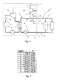
- reference numeral 1 generally designates a block diagram showing the principles of an air-conditioning system comprising a plurality of fan coils 2 opportunely distributed inside a building (not shown) for which it is wished to control the ambient temperature, and a refrigerating machine 3 suited to cool a service fluid 5, in particular a coolant liquid substantially composed of water, and make it circulate through a hydraulic circuit 4 that connects the fan coils 2 to the refrigerating machine 3 itself.
- the refrigerating machine 3 comprises an internal circuit 6, in which a working fluid 7 consisting of a refrigerant circulates, and an output circuit 8, which connects to the hydraulic circuit 4 of the system 1 in correspondence to an inlet 9 and an outlet 10 of the refrigerating machine 3.
- a series of devices are arranged along the internal circuit 6 to implement a refrigeration cycle on the working fluid 7, and in particular, a first heat exchanger 11 through which the internal circuit 6 and the output circuit 8 pass and which functions as an evaporator to make the working fluid 7 evaporate at low pressure, absorbing heat from the service fluid 5; a compressor 12, preferably of the scroll type, to carry out adiabatic compression on the working fluid 7 in the vapour state; a second heat exchanger 13 functioning as a condenser, that is to make the working fluid 7 condense so as to release the previously absorbed heat to the outside, and an expansion valve 14 to cool the working fluid 7 and make it partially evaporate so that it is ready for another cycle.
- the hydraulic circuit 4 of the system 1 and the output circuit 8 of the refrigerating machine 3 form a so-called hydronic circuit 15, comprising a delivery branch 16, along which the service fluid 5 circulates in a direction D from the heat exchanger 11 to the fan coils 2, and a return branch 17, along which the service fluid 5 returns to the heat exchanger 11. Circulation of the service fluid 5 in direction D is guaranteed by a pump 18 placed along the return branch 17.
- the refrigerating machine 3 comprises a control device 19 to control the switching on and off of the compressor 12 based on the delivery temperature TLDV of the service fluid 5.
- the control device 19 comprises a temperature sensor 20 placed along the delivery branch 16 at the outlet 10 of the refrigerating machine 3 to provide a first signal SDLV representing the delivery temperature TDLV and an electronic control unit 21 suited to switch the compressor 12 on and off on the basis of a comparison between a measurement of the delivery temperature TDLV, provided via the SDLV signal, and a pair of temperature thresholds such that the delivery temperature TDLV converges to a delivery temperature set point between the two temperature thresholds.
- the control device 19 comprises a filter 22 connected in input with the sensor 20 to receive the signal SDLV and in output with the electronic control unit 21 to supply a corresponding signal SCTRL obtained by damping the dynamics of the SDLV signal according to a model that reconstructs the dynamic behaviour of a common storage tank.
- the SCTRL signal represents a delivery temperature with dampened dynamics, in the time domain, on the basis of which control of the compressor 12 is performed. In other words, a delivery temperature measurement is extracted from the SCTRL signal and compared with the above-mentioned temperature thresholds to switch the compressor 12 on or off.
- stratification which consists in a division of the service fluid into layers according to the temperature
- mixing which consists in the fact that part of the incoming service fluid is typically colder than that inside and absorbs part of the heat of the latter, converging to a temperature that can be defined as one of equilibrium.
- the delay T represents the delay due to the stratification and parameter P is proportional to a mixing coefficient, which defines the volume percentage of the service fluid 5 in the tank that is affected by the mixing phenomena, at the density of the service fluid 5 in the hydronic circuit 15 expressed in kg/m 3 ad at a storage volume expressed in m 3 that it is wished to simulate, and is inversely proportional to the mass flow of the service fluid expressed in kg/s.
- Figure 2 shows a table in which a series of values are listed that the parameters T and P must assume in order to simulate a corresponding series of tank volume values expressed in L/kW, i.e. expressed in litres with reference to the nominal power of the compressor 12. These values have been determined through experimental tests, applying a method known as the area method, which allows a system to be identified via its response to an input signal, such as a unitary step for example.
- the best compromise between damping the dynamics of the system 1 and the regulating speed of the delivery temperature TDLV is obtained by sizing the filter 22 for intermediate tank volumes, between 4 and 6 L/kW for example, and preferably for a tank volume value equal to 5 L/kW, to which there is a corresponding delay T substantially equal to 32.6 s and a parameter P substantially equal to 70.8 s.
- the diagram of the principle of the refrigerating machine 3 shown in Figure 1 can also generically describe a machine suited to heat the service fluid 5 for the purpose of heating the environments in which the fan coils 2 are placed, for example a refrigerating machine 3 of the type operating as a heat pump.
- the compressor 12 is configured so as to perform the refrigeration cycle in the opposite sense to that previously described, such that the heat exchanger 11 functions as a condenser to transfer heat from the working fluid 7 to the service fluid 5 and the heat exchanger 13 functions as an evaporator.
- the sizing of the filter 22 is virtually independent of the fact of cooling or heating the service fluid 5.
- the control device 19 provided with the filter 22 is also applicable to a refrigerating machine suited to heat the service fluid 5.
- control device 19 for a refrigerating machine 3 is to allow the elimination of the storage tank on the delivery branch 16 of the hydronic circuit 15, whilst still guaranteeing the necessary stability of the air-conditioning system 1 thanks to the presence of the filter 22, which defines a virtual storage tank.
Landscapes
- Engineering & Computer Science (AREA)
- Physics & Mathematics (AREA)
- Mechanical Engineering (AREA)
- Thermal Sciences (AREA)
- General Engineering & Computer Science (AREA)
- Air Conditioning Control Device (AREA)
- Devices That Are Associated With Refrigeration Equipment (AREA)
- Control Of Temperature (AREA)
Description
- The present invention concerns a control device for a refrigerating machine according to
claim 1. - In particular, the present invention finds useful, but not exclusive, application in the regulation of the delivery temperature of a service fluid in output from a water chiller for centralized air-conditioning systems, to which the following description shall make explicit reference without, however, any loss of generality.
- As is known, a centralized air-conditioning system for the control of the ambient temperature in a building comprises a plurality of fan coils, opportunely distributed inside the building and connected with each other via a hydraulic circuit, and a centralized refrigerating machine suited to cool a service fluid, in particular a coolant liquid substantially composed of water, and to convey this service fluid to the various fan coils via said hydraulic circuit.
- This refrigerating machine, normally indicated by the term "chiller", comprises an internal circuit in which a working fluid consisting of a refrigerant circulates, an output circuit that connects to the hydraulic circuit of the air-conditioning system in correspondence to the unit's inlet and outlet to form, together with said hydraulic circuit, a so-called hydronic circuit, a heat exchanger through which the internal circuit and the output circuit pass for heat exchange between the working fluid and the service fluid, and one or more compressors for implementing a refrigeration cycle on the working fluid through compression of the working fluid itself.
- Electronic control devices are also known of for controlling the switching on and off of the compressors on the basis of a direct comparison between a measurement of the temperature of the service fluid in output from the refrigerating machine, or rather the delivery temperature of the service fluid, and a pair of temperature thresholds such that the delivery temperature converges to a predetermined set point value. For instance, the U.S. patent application published with number
US 2005/0235669 A1 discloses a control device according to the preamble ofclaim 1 for controlling the on/off switching of the compressor as a function of the comparison between the sensed temperature of an evaporating pipe and a pair of threshold temperatures. - Moreover, the refrigerating machine is typically equipped with a storage tank applied on the delivery branch of the hydronic circuit at a short distance from the heat exchanger to produce thermal inertia in the hydronic circuit that slows down the dynamics of the air-conditioning system in terms of speed of temperature variation in the service fluid so as to avoid phenomena that could induce instability in the system, such as undesired oscillations phenomena in the regulator valves of the fan coils for example. The delivery temperature, on the basis of which the switching on and off of the compressors is controlled, is typically taken downstream of the storage tank.
- The storage tank is usually housed inside the metal casing that encloses the various mechanical components of the refrigerating machine, and so the size and cost of the refrigerating machine heavily depend on its presence. Therefore, for reasons of cost and overall dimensions, it is often attempted to reduce or even eliminate the storage tank, consequently making a refrigerating machine potentially capable of inducing the above-mentioned drawbacks.
- The object of the present invention is to create a control device for a refrigerating machine and a refrigerating machine that allows the drawbacks caused by the absence of the storage tank to be overcome and that, at the same time, are simple and economic to manufacture.
- According to the present invention, a control device for a refrigerating machine and a refrigerating machine in accordance with the attached claims are provided.
- The present invention shall now be described with reference to the attached drawings, which illustrate a non-limitative example of embodiment, in which:
-
Figure 1 shows a block diagram of an air-conditioning system comprising a refrigerating machine equipped with a control device in accordance with the present invention; and -
Figure 2 shows a table of values with which to configure certain parameters of the control device inFigure 1 . - In
Figure 1 ,reference numeral 1 generally designates a block diagram showing the principles of an air-conditioning system comprising a plurality offan coils 2 opportunely distributed inside a building (not shown) for which it is wished to control the ambient temperature, and a refrigeratingmachine 3 suited to cool aservice fluid 5, in particular a coolant liquid substantially composed of water, and make it circulate through a hydraulic circuit 4 that connects thefan coils 2 to the refrigeratingmachine 3 itself. - The refrigerating
machine 3 comprises an internal circuit 6, in which aworking fluid 7 consisting of a refrigerant circulates, and anoutput circuit 8, which connects to the hydraulic circuit 4 of thesystem 1 in correspondence to an inlet 9 and anoutlet 10 of the refrigeratingmachine 3. A series of devices are arranged along the internal circuit 6 to implement a refrigeration cycle on the workingfluid 7, and in particular, afirst heat exchanger 11 through which the internal circuit 6 and theoutput circuit 8 pass and which functions as an evaporator to make the workingfluid 7 evaporate at low pressure, absorbing heat from theservice fluid 5; acompressor 12, preferably of the scroll type, to carry out adiabatic compression on the workingfluid 7 in the vapour state; asecond heat exchanger 13 functioning as a condenser, that is to make the workingfluid 7 condense so as to release the previously absorbed heat to the outside, and anexpansion valve 14 to cool the workingfluid 7 and make it partially evaporate so that it is ready for another cycle. - The hydraulic circuit 4 of the
system 1 and theoutput circuit 8 of the refrigeratingmachine 3 form a so-calledhydronic circuit 15, comprising adelivery branch 16, along which theservice fluid 5 circulates in a direction D from theheat exchanger 11 to thefan coils 2, and areturn branch 17, along which theservice fluid 5 returns to theheat exchanger 11. Circulation of theservice fluid 5 in direction D is guaranteed by apump 18 placed along thereturn branch 17. - In addition, the refrigerating
machine 3 comprises acontrol device 19 to control the switching on and off of thecompressor 12 based on the delivery temperature TLDV of theservice fluid 5. More in detail, thecontrol device 19 comprises atemperature sensor 20 placed along thedelivery branch 16 at theoutlet 10 of the refrigeratingmachine 3 to provide a first signal SDLV representing the delivery temperature TDLV and anelectronic control unit 21 suited to switch thecompressor 12 on and off on the basis of a comparison between a measurement of the delivery temperature TDLV, provided via the SDLV signal, and a pair of temperature thresholds such that the delivery temperature TDLV converges to a delivery temperature set point between the two temperature thresholds. - In accordance with the present invention, the
control device 19 comprises afilter 22 connected in input with thesensor 20 to receive the signal SDLV and in output with theelectronic control unit 21 to supply a corresponding signal SCTRL obtained by damping the dynamics of the SDLV signal according to a model that reconstructs the dynamic behaviour of a common storage tank. The SCTRL signal represents a delivery temperature with dampened dynamics, in the time domain, on the basis of which control of thecompressor 12 is performed. In other words, a delivery temperature measurement is extracted from the SCTRL signal and compared with the above-mentioned temperature thresholds to switch thecompressor 12 on or off. - More precisely, the
filter 22 is modelled as a first order system with delay, of which the transfer function to the Laplace transform domain is given by:
where T defines a delay between the input signal SDLV and the output signal SCTRL, and P represents a pole of the transfer function. - Therefore, by opportunely sizing the parameters T and P of function (1), it is possible to define a virtual storage tank that simulates the presence of a storage tank of the desired characteristics.
- Indeed, two different phenomena occur, to differing extents, inside a storage tank: stratification, which consists in a division of the service fluid into layers according to the temperature, and mixing, which consists in the fact that part of the incoming service fluid is typically colder than that inside and absorbs part of the heat of the latter, converging to a temperature that can be defined as one of equilibrium. Consequently, the delay T represents the delay due to the stratification and parameter P is proportional to a mixing coefficient, which defines the volume percentage of the
service fluid 5 in the tank that is affected by the mixing phenomena, at the density of theservice fluid 5 in thehydronic circuit 15 expressed in kg/m3 ad at a storage volume expressed in m3 that it is wished to simulate, and is inversely proportional to the mass flow of the service fluid expressed in kg/s. -
Figure 2 shows a table in which a series of values are listed that the parameters T and P must assume in order to simulate a corresponding series of tank volume values expressed in L/kW, i.e. expressed in litres with reference to the nominal power of thecompressor 12. These values have been determined through experimental tests, applying a method known as the area method, which allows a system to be identified via its response to an input signal, such as a unitary step for example. The best compromise between damping the dynamics of thesystem 1 and the regulating speed of the delivery temperature TDLV is obtained by sizing thefilter 22 for intermediate tank volumes, between 4 and 6 L/kW for example, and preferably for a tank volume value equal to 5 L/kW, to which there is a corresponding delay T substantially equal to 32.6 s and a parameter P substantially equal to 70.8 s. - It is worthwhile to note that the diagram of the principle of the refrigerating
machine 3 shown inFigure 1 can also generically describe a machine suited to heat theservice fluid 5 for the purpose of heating the environments in which thefan coils 2 are placed, for example a refrigeratingmachine 3 of the type operating as a heat pump. In this type of refrigeratingmachine 3, thecompressor 12 is configured so as to perform the refrigeration cycle in the opposite sense to that previously described, such that theheat exchanger 11 functions as a condenser to transfer heat from the workingfluid 7 to theservice fluid 5 and theheat exchanger 13 functions as an evaporator. Furthermore, the sizing of thefilter 22 is virtually independent of the fact of cooling or heating theservice fluid 5. Thus, thecontrol device 19 provided with thefilter 22 is also applicable to a refrigerating machine suited to heat theservice fluid 5. - The main advantage of the above-described
control device 19 for a refrigeratingmachine 3 is to allow the elimination of the storage tank on thedelivery branch 16 of thehydronic circuit 15, whilst still guaranteeing the necessary stability of the air-conditioning system 1 thanks to the presence of thefilter 22, which defines a virtual storage tank.
Claims (5)
- Control device for a refrigerating machine (3) comprising a compressor (12), the control device (19) comprising temperature sensor means (20) to provide a first signal (SDLV) representing the delivery temperature (TDLV) of a service fluid (5) in output from the refrigerating machine (3), a control unit (21) suited to switch the compressor (12) on and off according to the first signal (SDLV), and signal damping means (22) to receive the first signal (SDLV) and to supply a corresponding dampened second signal (SCTRL) obtained by damping the dynamics of the first signal (SDLV) and suitable for being fed in input to the control unit (21) to control the said switching on and off of the compressor (12); being characterized in that said damping means comprising a first order filter (22) with delay to simulate an accumulation of said service fluid (5).
- Device according to claim 1, in which said filter (22) has a Laplace transform domain transfer function given by:

wherein T defines a delay between said first signal (SDLV) in input to the filter and said second signal (SCTRL) in output from the filter (22) and P is an accumulation parameter proportional to a storage volume of service fluid (5) that it is wished to simulate and to a mixing coefficient of the service fluid (5) in said storage volume. - Device according to claim 2, in which said filter (22) is sized for a value of said storage volume to simulate in the range from 4 to 6 L/kW.
- Device according to claim 2 or 3, in which said delay (T) between said first signal (SDLV) and said second signal (SCTRL) is equal to 32.6 s and said accumulation parameter (P) is equal to 70.8 s.
- Refrigerating machine (3) comprising a compressor (12) and a control device (19) for switching the compressor (12) on and off according to a measurement of the delivery temperature (TDLV) of a service fluid (5) in output from the refrigerating machine (3), and characterized in that the control device (19) is of the type asserted in one of the claims 1 to 4.
Priority Applications (3)
| Application Number | Priority Date | Filing Date | Title |
|---|---|---|---|
| EP20070425351 EP2000758B1 (en) | 2007-06-04 | 2007-06-04 | Control device for a refrigerating machine |
| ES07425351T ES2362133T3 (en) | 2007-06-04 | 2007-06-04 | CONTROL DEVICE FOR A REFRIGERATION MACHINE. |
| DE200760012060 DE602007012060D1 (en) | 2007-06-04 | 2007-06-04 | Control device for a cooling device |
Applications Claiming Priority (1)
| Application Number | Priority Date | Filing Date | Title |
|---|---|---|---|
| EP20070425351 EP2000758B1 (en) | 2007-06-04 | 2007-06-04 | Control device for a refrigerating machine |
Publications (2)
| Publication Number | Publication Date |
|---|---|
| EP2000758A1 EP2000758A1 (en) | 2008-12-10 |
| EP2000758B1 true EP2000758B1 (en) | 2011-01-19 |
Family
ID=38657316
Family Applications (1)
| Application Number | Title | Priority Date | Filing Date |
|---|---|---|---|
| EP20070425351 Not-in-force EP2000758B1 (en) | 2007-06-04 | 2007-06-04 | Control device for a refrigerating machine |
Country Status (3)
| Country | Link |
|---|---|
| EP (1) | EP2000758B1 (en) |
| DE (1) | DE602007012060D1 (en) |
| ES (1) | ES2362133T3 (en) |
Families Citing this family (1)
| Publication number | Priority date | Publication date | Assignee | Title |
|---|---|---|---|---|
| HK1137899A2 (en) * | 2009-06-05 | 2010-08-06 | Ace Action Limited | Energy saver device, air-conditioning or refrigeration system and method for control of an air-conditioning or refrigeration system |
Family Cites Families (4)
| Publication number | Priority date | Publication date | Assignee | Title |
|---|---|---|---|---|
| US4292813A (en) * | 1979-03-08 | 1981-10-06 | Whirlpool Corporation | Adaptive temperature control system |
| JP2696398B2 (en) * | 1989-06-22 | 1998-01-14 | 株式会社ゼクセル | Compressor control device for vehicle air conditioner |
| KR100573770B1 (en) | 2004-04-24 | 2006-04-25 | 삼성전자주식회사 | Refrigerator and its control method |
| BRPI0403128A (en) * | 2004-08-02 | 2006-03-14 | Multibras Eletrodomesticos Sa | system for adjusting the temperature in a refrigeration appliance |
-
2007
- 2007-06-04 ES ES07425351T patent/ES2362133T3/en active Active
- 2007-06-04 EP EP20070425351 patent/EP2000758B1/en not_active Not-in-force
- 2007-06-04 DE DE200760012060 patent/DE602007012060D1/en active Active
Also Published As
| Publication number | Publication date |
|---|---|
| DE602007012060D1 (en) | 2011-03-03 |
| ES2362133T3 (en) | 2011-06-28 |
| EP2000758A1 (en) | 2008-12-10 |
Similar Documents
| Publication | Publication Date | Title |
|---|---|---|
| EP3699514B1 (en) | Systems and methods for controlling a refrigeration system | |
| US11279205B2 (en) | Method for operating a coolant circuit and vehicle air-conditioning system | |
| KR102353741B1 (en) | Systems and methods for controlling a refrigeration system | |
| EP3379178B1 (en) | Refrigerant control method | |
| EP3587933B1 (en) | Refrigerant transfer control in multi mode air conditioner with hot water generator | |
| EP2122276B1 (en) | Free-cooling limitation control for air conditioning systems | |
| JP6950191B2 (en) | Air conditioner | |
| CN106461300B (en) | Cooling system | |
| JP2009031866A (en) | Flow control valve and flow control method | |
| JP6545252B2 (en) | Refrigeration cycle device | |
| EP3538824A1 (en) | Dual mass cooling precision system | |
| US20130213066A1 (en) | Refrigeration arrangement and methods for reducing charge migration | |
| EP2631572A2 (en) | Dual capillary tube / heat exchanger in combination with cycle priming for reducing charge migration | |
| WO2018110185A1 (en) | Refrigerant circuit system and method for controlling refrigerant circuit system | |
| KR920006705A (en) | Multiple air conditioner | |
| CN104422193A (en) | Refrigerating and heating liquid storage method, refrigerating and heating frost prevention method and air conditioning system | |
| AU2016257496A1 (en) | An improved temperature control system | |
| JP2009236403A (en) | Geothermal use heat pump device | |
| EP3736509B1 (en) | Refrigeration system with heat recovery | |
| CN104101140A (en) | Freezer or refrigerator and refrigeration system thereof | |
| EP2000754B1 (en) | Method for estimating the thermal load of a circuit for a service fluid at outlet from a refrigerating machine | |
| EP2000758A1 (en) | Control device for a refrigerating machine | |
| EP3332182B1 (en) | Chiller plant | |
| EP3674622A1 (en) | Fluid control for a variable flow fluid circuit in an hvacr system | |
| EP2012068A1 (en) | Method for regulating the delivery temperature of a service fluid in output from a refrigerating machine |
Legal Events
| Date | Code | Title | Description |
|---|---|---|---|
| PUAI | Public reference made under article 153(3) epc to a published international application that has entered the european phase |
Free format text: ORIGINAL CODE: 0009012 |
|
| AK | Designated contracting states |
Kind code of ref document: A1 Designated state(s): AT BE BG CH CY CZ DE DK EE ES FI FR GB GR HU IE IS IT LI LT LU LV MC MT NL PL PT RO SE SI SK TR |
|
| AX | Request for extension of the european patent |
Extension state: AL BA HR MK RS |
|
| RIN1 | Information on inventor provided before grant (corrected) |
Inventor name: SCODELLARO, ALESSANDRO Inventor name: ALBIERI, MICHELE Inventor name: BODO, CRISTIAN Inventor name: ZEN, ALESSANDRO Inventor name: CECCHINATO, LUCA Inventor name: BEGHI, ALESSANDRO |
|
| 17P | Request for examination filed |
Effective date: 20090608 |
|
| 17Q | First examination report despatched |
Effective date: 20090703 |
|
| AKX | Designation fees paid |
Designated state(s): DE ES FR GB IT |
|
| GRAP | Despatch of communication of intention to grant a patent |
Free format text: ORIGINAL CODE: EPIDOSNIGR1 |
|
| GRAS | Grant fee paid |
Free format text: ORIGINAL CODE: EPIDOSNIGR3 |
|
| GRAA | (expected) grant |
Free format text: ORIGINAL CODE: 0009210 |
|
| AK | Designated contracting states |
Kind code of ref document: B1 Designated state(s): DE ES FR GB IT |
|
| REG | Reference to a national code |
Ref country code: GB Ref legal event code: FG4D |
|
| REF | Corresponds to: |
Ref document number: 602007012060 Country of ref document: DE Date of ref document: 20110303 Kind code of ref document: P |
|
| REG | Reference to a national code |
Ref country code: DE Ref legal event code: R096 Ref document number: 602007012060 Country of ref document: DE Effective date: 20110303 |
|
| REG | Reference to a national code |
Ref country code: ES Ref legal event code: FG2A Ref document number: 2362133 Country of ref document: ES Kind code of ref document: T3 Effective date: 20110628 |
|
| PLBE | No opposition filed within time limit |
Free format text: ORIGINAL CODE: 0009261 |
|
| STAA | Information on the status of an ep patent application or granted ep patent |
Free format text: STATUS: NO OPPOSITION FILED WITHIN TIME LIMIT |
|
| 26N | No opposition filed |
Effective date: 20111020 |
|
| REG | Reference to a national code |
Ref country code: DE Ref legal event code: R097 Ref document number: 602007012060 Country of ref document: DE Effective date: 20111020 |
|
| REG | Reference to a national code |
Ref country code: FR Ref legal event code: PLFP Year of fee payment: 10 |
|
| REG | Reference to a national code |
Ref country code: FR Ref legal event code: PLFP Year of fee payment: 11 |
|
| PGFP | Annual fee paid to national office [announced via postgrant information from national office to epo] |
Ref country code: GB Payment date: 20170630 Year of fee payment: 11 Ref country code: FR Payment date: 20170629 Year of fee payment: 11 |
|
| PGFP | Annual fee paid to national office [announced via postgrant information from national office to epo] |
Ref country code: IT Payment date: 20170609 Year of fee payment: 11 |
|
| PGFP | Annual fee paid to national office [announced via postgrant information from national office to epo] |
Ref country code: ES Payment date: 20170724 Year of fee payment: 11 Ref country code: DE Payment date: 20170831 Year of fee payment: 11 |
|
| REG | Reference to a national code |
Ref country code: DE Ref legal event code: R119 Ref document number: 602007012060 Country of ref document: DE |
|
| GBPC | Gb: european patent ceased through non-payment of renewal fee |
Effective date: 20180604 |
|
| PG25 | Lapsed in a contracting state [announced via postgrant information from national office to epo] |
Ref country code: IT Free format text: LAPSE BECAUSE OF NON-PAYMENT OF DUE FEES Effective date: 20180604 Ref country code: DE Free format text: LAPSE BECAUSE OF NON-PAYMENT OF DUE FEES Effective date: 20190101 Ref country code: GB Free format text: LAPSE BECAUSE OF NON-PAYMENT OF DUE FEES Effective date: 20180604 Ref country code: FR Free format text: LAPSE BECAUSE OF NON-PAYMENT OF DUE FEES Effective date: 20180630 |
|
| REG | Reference to a national code |
Ref country code: ES Ref legal event code: FD2A Effective date: 20190916 |
|
| PG25 | Lapsed in a contracting state [announced via postgrant information from national office to epo] |
Ref country code: ES Free format text: LAPSE BECAUSE OF NON-PAYMENT OF DUE FEES Effective date: 20180605 |