EP2000754A2 - Procédé d'estimation de la charge thermique d'un circuit pour un fluide de service à la sortie d'une machine de refroidissement - Google Patents
Procédé d'estimation de la charge thermique d'un circuit pour un fluide de service à la sortie d'une machine de refroidissement Download PDFInfo
- Publication number
- EP2000754A2 EP2000754A2 EP08157531A EP08157531A EP2000754A2 EP 2000754 A2 EP2000754 A2 EP 2000754A2 EP 08157531 A EP08157531 A EP 08157531A EP 08157531 A EP08157531 A EP 08157531A EP 2000754 A2 EP2000754 A2 EP 2000754A2
- Authority
- EP
- European Patent Office
- Prior art keywords
- temperature
- refrigerating machine
- delivery
- tdlv
- thermal load
- Prior art date
- Legal status (The legal status is an assumption and is not a legal conclusion. Google has not performed a legal analysis and makes no representation as to the accuracy of the status listed.)
- Granted
Links
Images

Classifications
-
- F—MECHANICAL ENGINEERING; LIGHTING; HEATING; WEAPONS; BLASTING
- F25—REFRIGERATION OR COOLING; COMBINED HEATING AND REFRIGERATION SYSTEMS; HEAT PUMP SYSTEMS; MANUFACTURE OR STORAGE OF ICE; LIQUEFACTION SOLIDIFICATION OF GASES
- F25B—REFRIGERATION MACHINES, PLANTS OR SYSTEMS; COMBINED HEATING AND REFRIGERATION SYSTEMS; HEAT PUMP SYSTEMS
- F25B25/00—Machines, plants or systems, using a combination of modes of operation covered by two or more of the groups F25B1/00 - F25B23/00
- F25B25/005—Machines, plants or systems, using a combination of modes of operation covered by two or more of the groups F25B1/00 - F25B23/00 using primary and secondary systems
-
- F—MECHANICAL ENGINEERING; LIGHTING; HEATING; WEAPONS; BLASTING
- F25—REFRIGERATION OR COOLING; COMBINED HEATING AND REFRIGERATION SYSTEMS; HEAT PUMP SYSTEMS; MANUFACTURE OR STORAGE OF ICE; LIQUEFACTION SOLIDIFICATION OF GASES
- F25B—REFRIGERATION MACHINES, PLANTS OR SYSTEMS; COMBINED HEATING AND REFRIGERATION SYSTEMS; HEAT PUMP SYSTEMS
- F25B49/00—Arrangement or mounting of control or safety devices
- F25B49/02—Arrangement or mounting of control or safety devices for compression type machines, plants or systems
-
- F—MECHANICAL ENGINEERING; LIGHTING; HEATING; WEAPONS; BLASTING
- F25—REFRIGERATION OR COOLING; COMBINED HEATING AND REFRIGERATION SYSTEMS; HEAT PUMP SYSTEMS; MANUFACTURE OR STORAGE OF ICE; LIQUEFACTION SOLIDIFICATION OF GASES
- F25B—REFRIGERATION MACHINES, PLANTS OR SYSTEMS; COMBINED HEATING AND REFRIGERATION SYSTEMS; HEAT PUMP SYSTEMS
- F25B2600/00—Control issues
- F25B2600/02—Compressor control
- F25B2600/025—Compressor control by controlling speed
- F25B2600/0251—Compressor control by controlling speed with on-off operation
-
- F—MECHANICAL ENGINEERING; LIGHTING; HEATING; WEAPONS; BLASTING
- F25—REFRIGERATION OR COOLING; COMBINED HEATING AND REFRIGERATION SYSTEMS; HEAT PUMP SYSTEMS; MANUFACTURE OR STORAGE OF ICE; LIQUEFACTION SOLIDIFICATION OF GASES
- F25B—REFRIGERATION MACHINES, PLANTS OR SYSTEMS; COMBINED HEATING AND REFRIGERATION SYSTEMS; HEAT PUMP SYSTEMS
- F25B2700/00—Sensing or detecting of parameters; Sensors therefor
- F25B2700/21—Temperatures
- F25B2700/2117—Temperatures of an evaporator
- F25B2700/21171—Temperatures of an evaporator of the fluid cooled by the evaporator
- F25B2700/21172—Temperatures of an evaporator of the fluid cooled by the evaporator at the inlet
-
- F—MECHANICAL ENGINEERING; LIGHTING; HEATING; WEAPONS; BLASTING
- F25—REFRIGERATION OR COOLING; COMBINED HEATING AND REFRIGERATION SYSTEMS; HEAT PUMP SYSTEMS; MANUFACTURE OR STORAGE OF ICE; LIQUEFACTION SOLIDIFICATION OF GASES
- F25B—REFRIGERATION MACHINES, PLANTS OR SYSTEMS; COMBINED HEATING AND REFRIGERATION SYSTEMS; HEAT PUMP SYSTEMS
- F25B2700/00—Sensing or detecting of parameters; Sensors therefor
- F25B2700/21—Temperatures
- F25B2700/2117—Temperatures of an evaporator
- F25B2700/21171—Temperatures of an evaporator of the fluid cooled by the evaporator
- F25B2700/21173—Temperatures of an evaporator of the fluid cooled by the evaporator at the outlet
Definitions
- the present invention relates to a method for estimating the thermal load of a circuit for a service fluid at outlet from a refrigerating machine.
- the present invention finds advantageous, though not exclusive, application in the estimation of the thermal load of a hydronic circuit of centralized air-conditioning systems, to which the ensuing description will make explicit reference, without this implying any loss of generality.
- a centralized air-conditioning system for control of ambient temperature of a building comprises a plurality of fan coils, which are appropriately distributed inside the building and are connected to one another via a hydraulic circuit, and a centralized refrigerating machine designed to cool a service fluid, and in particular a liquid coolant substantially constituted by water, and to convey said service fluid to the various fan coils through said hydraulic circuit.
- Said refrigerating machine commonly referred to as "chiller"
- the hydraulic circuit of the air-conditioning system and the output circuit of the refrigerating machine form a so-called hydronic circuit.
- Said control systems basically implement a control logic of a proportional type in which turning-on and turning-off of the compressors is carried out on the basis of a direct comparison between a measurement of the return temperature or delivery temperature of the service fluid and a pair of temperature thresholds.
- the control systems referred to above present intrinsic limits due to temporal constraints between the instants of turning-on and turning-off of the compressors for the purpose of lengthening the service life thereof. Said constraints in effect limit the differential between the temperature thresholds to a minimum value, below which the compressors are forced to operate in technically prohibitive conditions of operation that can cause damage thereto. More in general, said temporal constraints mean that the control systems mentioned above do not enable, on the one hand, a good degree of precision of regulation of the temperature of the service fluid and, on the other hand, maximization of the energy efficiency of the air-conditioning system.
- the aim of the present invention is to provide a method for estimating the thermal load of a hydronic circuit of an air-conditioning system governed by a refrigerating machine and to provide a control device for the refrigerating machine implementing said method that will enable regulation of the delivery temperature in a precise way, and maximization of the energy efficiency of the system, and, at the same time, will be easy and inexpensive to produce.
- Provided according to the present invention are a method for estimating the thermal load of a service circuit for a service fluid at outlet from a refrigerating machine, a control device for a refrigerating machine, and a refrigerating machine in accordance with the annexed claims.
- FIG. 1 designated as a whole by 1 is an air-conditioning system comprising a plurality of fan coils 2 appropriately distributed inside a building (not illustrated) of which it is intended to control the ambient temperature, and a refrigerating machine 3 designed to cool and cause circulation, along a hydraulic circuit 4 that connects the fan coils 2 to the refrigerating machine 3 itself, of a service fluid 5, and in particular a liquid coolant substantially constituted by water.
- the refrigerating machine 3 typically comprises an internal circuit 6, circulating in which is an working fluid 7 constituted by a refrigerant fluid, and an output circuit 8, which closes on the hydraulic circuit 4 of the system 1 in an area corresponding to an inlet 9 and an outlet 10 of the refrigerating machine 3.
- Set along the internal circuit 6 are a series of devices for actuating a refrigerating cycle on the working fluid 7, and in particular: a first heat exchanger 11 traversed by the internal circuit 6 and by the output circuit 8 functioning as evaporator, i.e., for causing evaporation at low pressure of the working fluid 7 by absorbing heat from the service fluid 5; a compressor 12, preferably of a scroll type, for performing an adiabatic compression on the working fluid 7 in the vapour state; a second heat exchanger 13 functioning as condenser, i.e., for causing condensation of the working fluid 7 in such a way that it can release on the outside the heat previously absorbed; and an expansion valve 14 for cooling and causing partial evaporation of the working liquid 7 in such a way that it is ready for another cycle.
- a first heat exchanger 11 traversed by the internal circuit 6 and by the output circuit 8 functioning as evaporator, i.e., for causing evaporation at low pressure of the working fluid 7 by
- the hydraulic circuit 4 of the system 1 and the output circuit 8 of the refrigerating machine 3 form a so-called hydronic circuit 15, comprising a delivery branch 16, along which the service fluid 5 circulates in a direction D oriented from the heat exchanger 11 to the fan coils 2, and a return branch 17, along which the service fluid 5 returns to the heat exchanger 11.
- the circulation of the service fluid 5 in the direction D is guaranteed by a pump 18 set along the return branch 17.
- the refrigerating machine 3 is provided with a storage tank 19 set along the delivery branch 16 at a short distance from the heat exchanger 11 for producing a thermal inertia in the hydronic circuit 15 that slows down the dynamics of the system 1 in such a way as to prevent undesirable phenomena of oscillation in the regulation valves (not illustrated) of the fan coils 2.
- the presence of the storage tank 19 is optional.
- the refrigerating machine 3 further comprises a control device 20 for controlling turning-on and turning-off of the compressor 12 as a function of a delivery temperature TLDV of the service fluid 5.
- control device 20 comprises a first temperature sensor 21 set along the delivery branch 16 at output from the storage tank 19, i.e., at the outlet 10 of the refrigerating machine 3, for measuring the delivery temperature TDLV of the service fluid 5, a second temperature sensor 22 set along the return branch 17 in an area corresponding to the inlet 9 of the refrigerating machine 3 for measuring the return temperature TRET of the service fluid 5, which corresponds to a desired value of the temperature of evaporation of the working fluid 7 in the heat exchanger 11, a keypad 23 for receiving commands imparted by a user, and an electronic control unit 24 connected to the sensors 21 and 22, to the keypad 23 and to the compressor 12.
- the electronic control unit 24 is designed to control turning-on and turning-off of the compressor 12 as a function of the comparison between the delivery temperature TDLV and a pair of delivery-temperature thresholds in such a way that the delivery temperature TDLV will converge on a delivery-temperature set point TSET comprised between the two delivery-temperature thresholds.
- the electronic control unit 24 implements a method for estimating the thermal load of the hydronic circuit 15 in accordance with the present invention, said method being described in detail hereinafter for the case where the service fluid 5 is cooled for cooling the environments in which the fan coils 2 are arranged.
- the electronic control unit 24 is designed to regulate the delivery temperature TDLV by adapting the set point TSET and the temperature thresholds to the thermal load estimated.
- dividing ratio comprised between 0 and 1 that defines the ratio with which the delivery differential DM is divided between the two thresholds so as to be able to render them asymmetrical with respect to the set point TSET.
- the lower threshold TLOW and upper threshold THIG are maintained symmetrical with respect to the set point TSET; i.e., they are linked to the set point TSET via a dividing ratio R of 0.5.
- the lower threshold TLOW and upper threshold THIG can be adjusted irrespective of the set point TSET by acting on the delivery differential DM and on the dividing ratio R.
- the thermal load of the hydronic circuit 15 corresponds to the thermal load offered by the environment to be cooled.
- COP coefficient of performance
- the estimated thermal load is given in terms of fraction of load FL, i.e., in terms of ratio between the power that the refrigerating machine 3 must supply to cool the environment and the maximum refrigerating power that can be delivered by the refrigerating machine 3 in given nominal conditions.
- Turning-on or turning-off of the compressor 12 must respect precise temporal constraints between successive events of turning-on and/or turning-off in order to safeguard the integrity of the compressor 12 itself, i.e., it must respect a minimum time ⁇ t_ON_min between turning-on and turning-off, a minimum time ⁇ t_OFF_min between turning-off and turning-on, and a minimum time ⁇ t_ON_ON_min between two successive turning-on events.
- Figure 2 shows the graph of the theoretical on and off times ⁇ t_ON and ⁇ t_OFF as the fraction of load FL varies in the case of the following temporal constraints:
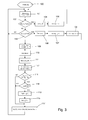
- Figure 3 illustrates a flowchart that describes the regulation of the delivery temperature TDLV as a function of the estimate of the thermal load.
- the method envisages a step of initialization of variables (block 100), in which:
- the delivery temperature TDLV and the return temperature TRET are measured via the respective sensors 21 and 22 (block 101).
- a measurement of the delivery temperature TDLV is compared with the lower threshold TLOW (block 102) and the upper threshold THIG (block 103). If the delivery temperature TDLV is lower than or equal to the lower threshold TLOW, then the compressor 12 is turned off (block 104). Instead, if the delivery temperature TDLV is higher than or equal to the upper threshold THIG, then the compressor 12 is turned on (block 105).
- the instants of time of the events of turning-off and turning-on are stored in the respective variables turning-off instant t_OFF (block 106) and turning-on instant t_ON (block 107). In addition, at each turning-on event a counter N_ON for counting the number of turning-on events is incremented (block 108).
- the turning-on event determines start of the on-off cycle of the compressor 12, and at a point corresponding to said event a series of calculations is triggered, which leads to the estimation of the thermal load and to the adaptation of the set point TSET and of the thresholds TLOW and THIG to the estimated thermal load.
- an effective on time ⁇ t_ON_real, an effective off time ⁇ t _OFF_real, and an effective cycle time ⁇ t_TOT_real of the compressor 12 are determined, the latter being equal to the sum ⁇ t_ON_ real + ⁇ t_OFF_real (block 109), and a mean delivery temperature TDLVmean is determined by averaging the measurements of delivery temperature TDLV over the effective cycle time ⁇ t_TOT_real (block 110).
- the thermal load is estimated as a function of the measurements of delivery temperature TDLV and return temperature TRET and is supplied, as mentioned previously, in terms of an estimated fraction of load FL (block 111).
- the set point TSET is adjusted via an adaptation thereof to the fraction of load FL (block 113).
- the adaptation of the set point TSET to the fraction of load FL is enabled only after verification of the fact that the number of turning-on events N_ON has reached a minimum number of turning-on events N_ON_min, preferably equal to 4 (block 114).
- This control has the purpose of enabling a sufficient stabilization of the process of estimation of the fraction of load FL in so far as the process of estimation is perturbed by the regulation of the set point TSET.
- ⁇ TSET is a set-point step produced by the regulation of the set point TSET with respect to the previous value assumed by the set point TSET itself, as will be explained hereinafter, and a down count is activated starting from said value of wait time t_WAIT (block 115). Only at the end of said down count is the regulation of the set point TSET enabled again (block 116). Also this solution has the purpose of enabling a sufficient stabilization of the process of estimation of the fraction of load FL.
- the lower threshold TLOW and upper threshold THIG are adjusted as a function of the fraction of load FL, of the mean delivery temperature TDLVmean, and of the set point TSET (block 117).
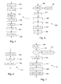
- Figure 4 illustrates a portion of flowchart regarding block 111 of Figure 3 , which illustrates the substeps regarding determination of the fraction of load FL of the hydronic circuit 15 in accordance with the present invention.
- ⁇ TQ is the difference of temperature between the inlet and the outlet of the set of fan coils 2 produced by the thermal power that the environment supplies to the system 1
- the method for estimating the thermal load envisages estimating the system parameter k to tune a subsequent estimation of the fraction of load FL with the characteristics of capacity and mass flowrate of the hydronic circuit 15 (block 200), and subsequently of acquiring samples of delivery temperature TDLV(n) and return temperature TRET(n) by sampling the outputs of the sensors 21 and 22 with a sampling period ts (block 201) and estimating the temperature difference ⁇ TQ by processing the samples of delivery temperature TDLV(n) and return temperature TRET(n) via a discrete Kalman filter (block 202) that expresses Eq.
- u(n), x(n) and y(n) are, respectively, the vector of the inputs, of the states, and of the outputs of the system at the discrete instant n
- u n TDLV n TRET n
- F 1 0 ts k 1 - ts k
- G [ 0 ts k ]
- H 0 1
- J 0 .
- the difference of temperature ⁇ TQ estimated undergoes a low-pass filtering (block 203), for example via a first-order Chebyshev filter with a cut-off pulsation of 0.003 rad/s and a peak pass-band ripple of 3dBp, and is then processed to obtain a mean value ⁇ TQmean over the measured cycle time ⁇ tCYCLE (block 204).
- a low-pass filtering for example via a first-order Chebyshev filter with a cut-off pulsation of 0.003 rad/s and a peak pass-band ripple of 3dBp
- Figure 5 illustrates a portion of flowchart that describes in greater detail the step of estimation of the system parameter k indicated in block 200 in Figure 4 .
- the system parameter k is estimated on the basis of a formula obtained from an energy-balance equation in terms of temperature similar to Eq. (6) and expressed as a function of temperatures of which measurements are available, i.e., of the delivery temperature TDLV and of the return temperature TRET.
- ⁇ 1 and ⁇ 2 are the heat-propagation delays introduced, respectively, by the pipes of the hydronic circuit 15 and by the storage tank 19, assuming the outlet of the heat exchanger 11 as origin of a thermal variation, and t is an instant of time in which the system parameter k is estimated.
- the deviation time ⁇ is preferably five seconds.
- the heat-propagation delay ⁇ 2 due to the storage tank 19 is determined as a difference between the turning-on instant t_ON and a first sing-inversion instant, in which the first derivative of the delivery temperature TDLV passes from a positive value to a negative value (block 303).
- a heat-propagation delay ⁇ 3 for the entire hydronic circuit 15, i.e., between the outlet and the inlet of the exchanger block 304.
- the estimation of the system parameter k in the way described above corresponds to an estimation of the characteristics of capacity and mass flowrate of the hydronic circuit 15 that enables automatic tuning of the estimation of the fraction of load FL to the characteristics of the system 1. This operation is certainly necessary upon initial turning-on of the refrigerating machine 3 after it has been connected to a new system 1, but also during normal operation of the system 1 itself for identifying variations of load due to de-activation of one or more fan coils 2.
- Figure 6 illustrates a portion of flowchart that describes in greater detail the step of regulation of the set point TSET indicated in block 113 in Figure 3 .
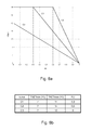
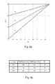
- This step envisages calculation of a new value of the set point TSET using a formula that expresses the temperature of set point TSET as a function of the estimated fraction of load FL (block 400) :
- TSET ⁇ TSET max if FL ⁇ FLI TSET min + TSET max - TSET min ⁇ 1 - FL 1 - FLI otherwise
- TSETmin is the minimum value of the set point TSET corresponding to the fraction of maximum load equal to unity
- TSETmax is a maximum value of the set point TSET corresponding to the fraction of load that is equal to zero
- FLI is a value of fraction of load that separates the relation into a first portion in which the set point TSET is constant and a second portion in which the set point TSET decreases linearly as the fraction of load FL varies.
- Eq. (12) is considered for three different sets of values of the parameters TSETmin, TSETmax and FLI gathered together in the table appearing in Figure 8a.
- Figure 8b represents the three different versions of Eq. (12) via three respective curves plotted in the plane TSET, FLI and designated by C1, C2 and C3.
- the three sets of parameters TSETmin, TSETmax and FLI, and hence the three curves C1, C2 and C3, correspond to three different modes of operation of the refrigerating machine 3 which can be selected by the user.
- Corresponding to the curve C1 is a default mode of operation, which ensures the best compromise between energy efficiency of the refrigerating machine 3 and precision of regulation of the delivery temperature TDLV, in so far as the new value of the set point TSET can vary between the minimum value TSETmin and the maximum value TSETmax for a wide range of values of fractions of load FL, i.e., from 0.3 to 1.
- a set-point step ⁇ TSET is determined by calculating the difference between the value just calculated and the preceding value of the set point TSET and setting an upper limit for the step ⁇ TSET at a maximum value ⁇ TSETmax preferably of 4°C (block 401), and the set point TSET is updated by applying instantaneously the set-point step ⁇ TSET to the preceding set point TSET (block 402).
- Figure 7 illustrates a portion of flowchart that describes in greater detail the step of regulation of the lower threshold TLOW and upper threshold THIG indicated in block 117 in Figure 3 .
- the delivery differential DM is too small, i.e., it does not enable respect of the temporal constraints between successive turning-on and/or turning-off events, and hence it is necessary to increase it by an amount ⁇ DM, preferably of 0.2°C (block 502); otherwise, a new value of delivery differential DM is determined in such a way that said error E ⁇ t tends to zero (block 503).
- the new value of delivery differential DM is determined using a numeric method for search for the zeroes of a function, known as chord method or secant method, by applying it to a target function constituted by the error E ⁇ t as a function of the delivery differential DM. This regulation has the purpose of maximizing the number of turning-on events of the compressor 12 per hour in due respect of the aforesaid temporal constraints.
- the chord method or secant method is used applying it to a target function constituted by the error ETDLV as a function of the dividing ratio R. This regulation has the purpose of speeding up convergence of the delivery temperature TDLV towards the set point TSET.
- the lower threshold TLOW and the upper threshold THIG are calculated as a function of the dividing ratio R, of the delivery differential DM, and of the set point TSET applying Eq. (1) and Eq. (2), respectively (block 506).
- the working diagram of the refrigerating machine 3 illustrated in Figure 1 can generically describe also a machine designed to heat the service fluid 5 in order to heat the environments in which the fan coils 2 are set, for example, a refrigerating machine 3 of the type operating as heat pump.
- the compressor 12 is configured so as to carry out the refrigerating cycle in a reverse mode with respect to what was described previously, i.e., in such a way that the heat exchanger 11 functions as condenser for transferring heat from the working fluid 7 to the service fluid 5, and the heat exchanger 13 functions as evaporator.
- the method for estimating the thermal load in accordance with the present invention is hence applicable also to the case where the refrigerating machine 3 is designed to heat the service fluid 5, it being sufficient simply to reverse the mechanism of some of the steps described and change the value of some parameters, and in particular:
- the main advantage of the method for estimating the thermal load of a hydronic circuit 15 described above as compared to the known art is that it increases the overall efficiency of the system 1 albeit maintaining a good precision of regulation of the delivery temperature TDLV of the service fluid 5 in the hydronic circuit 15.
- the adaptation of the set point TSET to the thermal load of the hydronic circuit 15 enables the refrigerating machine 3 to respond promptly to the variations of thermal load of the environment of which it is intended to control the temperature in such a way that the evaporation temperature can increase in the case where the machine is configured for cooling the service fluid 5, or in such a way that the condensation temperature can decrease in the case where the machine is configured for heating the service fluid 5, thus maximizing the coefficient of performance in all the operating conditions.
- the adaptation of the two delivery-temperature thresholds TLOW and THIG to the estimated fraction of load FL enables maximization of the number of turning-on events of the compressor 12 per hour within the limit imposed by the temporal constraints between successive turning-on and/or turning-off events via regulation of the delivery differential DM and enables speeding up of the convergence of the delivery temperature TDLV to the set point TSET via the regulation of the dividing ratio R.
- Another advantage is that it enables automatic adaptation of the refrigerating machine 3 to the type of system 1 in which it is installed and rapid identification of variations of thermal load due to de-activation of one or more fan coils 2, thanks to the operation of estimation of the system parameter k that expresses the characteristics of capacity and flowrate of the system 1.
Landscapes
- Engineering & Computer Science (AREA)
- Physics & Mathematics (AREA)
- Mechanical Engineering (AREA)
- Thermal Sciences (AREA)
- General Engineering & Computer Science (AREA)
- Air Conditioning Control Device (AREA)
- Devices That Are Associated With Refrigeration Equipment (AREA)
Applications Claiming Priority (1)
| Application Number | Priority Date | Filing Date | Title |
|---|---|---|---|
| ITBO20070399 ITBO20070399A1 (it) | 2007-06-04 | 2007-06-04 | Metodo per stimare il carico termico di un circuito per un fluido di servizio in uscita da una macchina frigorifera |
Publications (3)
| Publication Number | Publication Date |
|---|---|
| EP2000754A2 true EP2000754A2 (fr) | 2008-12-10 |
| EP2000754A3 EP2000754A3 (fr) | 2013-03-27 |
| EP2000754B1 EP2000754B1 (fr) | 2015-11-11 |
Family
ID=39817440
Family Applications (1)
| Application Number | Title | Priority Date | Filing Date |
|---|---|---|---|
| EP08157531.8A Not-in-force EP2000754B1 (fr) | 2007-06-04 | 2008-06-04 | Procédé d'estimation de la charge thermique d'un circuit pour un fluide de service à la sortie d'une machine de refroidissement |
Country Status (3)
| Country | Link |
|---|---|
| EP (1) | EP2000754B1 (fr) |
| ES (1) | ES2560514T3 (fr) |
| IT (1) | ITBO20070399A1 (fr) |
Cited By (5)
| Publication number | Priority date | Publication date | Assignee | Title |
|---|---|---|---|---|
| US20150369641A1 (en) * | 2011-05-26 | 2015-12-24 | Hach Company | Fluid quantification instrument and method |
| EP3647681A1 (fr) * | 2018-10-31 | 2020-05-06 | Klaus Scherrieble | Système et procédé de régulation et de surveillance de la réfrigération pour une unité |
| DE102020118762A1 (de) | 2020-07-16 | 2022-01-20 | Vaillant Gmbh | Massenstromschätzung in linksdrehenden Kreisprozessen |
| CN114971029A (zh) * | 2022-05-30 | 2022-08-30 | 重庆邮电大学 | 基于nsga-iii算法的乡村家庭综合能源优化调度方法 |
| CN118089209A (zh) * | 2024-04-25 | 2024-05-28 | 深圳市思科顿环保科技有限公司 | 一种空气能冷暖机工作数据实时监测方法 |
Family Cites Families (9)
| Publication number | Priority date | Publication date | Assignee | Title |
|---|---|---|---|---|
| JPS5934257B2 (ja) * | 1979-07-06 | 1984-08-21 | 三菱電機株式会社 | 水冷却装置 |
| FI922031A0 (fi) * | 1991-10-23 | 1992-05-05 | Antti Aarne Ilmari Lange | Foerfarande foer kalman-filter i stora system. |
| JPH05296516A (ja) * | 1992-04-18 | 1993-11-09 | Osaka Gas Co Ltd | 冷房装置 |
| US5735134A (en) * | 1996-05-30 | 1998-04-07 | Massachusetts Institute Of Technology | Set point optimization in vapor compression cycles |
| JPH10300163A (ja) * | 1997-04-28 | 1998-11-13 | Mitsubishi Electric Corp | 空気調和装置の運転方法及び空気調和装置 |
| US5911127A (en) * | 1997-06-05 | 1999-06-08 | Carrier Corporation | Prediction of chiller compressor motor overheating |
| DE19818860C2 (de) * | 1998-04-28 | 2001-04-19 | Daimler Chrysler Ag | Verfahren und Einrichtung zur Detektion und Lokalisation von Sensorfehlern in Kraftfahrzeugen |
| JP3693038B2 (ja) * | 2002-05-22 | 2005-09-07 | ダイキン工業株式会社 | 冷凍装置の制御方法および冷凍装置 |
| JP3933076B2 (ja) * | 2003-03-28 | 2007-06-20 | 株式会社日立製作所 | 空気調和装置 |
-
2007
- 2007-06-04 IT ITBO20070399 patent/ITBO20070399A1/it unknown
-
2008
- 2008-06-04 EP EP08157531.8A patent/EP2000754B1/fr not_active Not-in-force
- 2008-06-04 ES ES08157531.8T patent/ES2560514T3/es active Active
Cited By (6)
| Publication number | Priority date | Publication date | Assignee | Title |
|---|---|---|---|---|
| US20150369641A1 (en) * | 2011-05-26 | 2015-12-24 | Hach Company | Fluid quantification instrument and method |
| US10309808B2 (en) * | 2011-05-26 | 2019-06-04 | Hach Company | Fluid quantification instrument and method |
| EP3647681A1 (fr) * | 2018-10-31 | 2020-05-06 | Klaus Scherrieble | Système et procédé de régulation et de surveillance de la réfrigération pour une unité |
| DE102020118762A1 (de) | 2020-07-16 | 2022-01-20 | Vaillant Gmbh | Massenstromschätzung in linksdrehenden Kreisprozessen |
| CN114971029A (zh) * | 2022-05-30 | 2022-08-30 | 重庆邮电大学 | 基于nsga-iii算法的乡村家庭综合能源优化调度方法 |
| CN118089209A (zh) * | 2024-04-25 | 2024-05-28 | 深圳市思科顿环保科技有限公司 | 一种空气能冷暖机工作数据实时监测方法 |
Also Published As
| Publication number | Publication date |
|---|---|
| ITBO20070399A1 (it) | 2008-12-05 |
| ES2560514T3 (es) | 2016-02-19 |
| EP2000754B1 (fr) | 2015-11-11 |
| EP2000754A3 (fr) | 2013-03-27 |
Similar Documents
| Publication | Publication Date | Title |
|---|---|---|
| EP2588818B1 (fr) | Procédé permettant d'actionner un système à compression de vapeur utilisant une valeur de sous-refroidissement | |
| US10401068B2 (en) | Air cooled chiller with heat recovery | |
| US6554196B2 (en) | Temperature control device | |
| US9810472B2 (en) | Synchronous temperature rate control for refrigeration with reduced energy consumption | |
| US10480838B2 (en) | Control device for refrigeration cycle apparatus, and control method for refrigeration cycle apparatus, and refrigeration cycle apparatus | |
| US10107531B2 (en) | Method for controlling a chiller system | |
| US9719700B2 (en) | Method for matching refrigeration load to compressor capacity | |
| EP2000754B1 (fr) | Procédé d'estimation de la charge thermique d'un circuit pour un fluide de service à la sortie d'une machine de refroidissement | |
| KR20190101675A (ko) | 공조설비의 전자팽창밸브 제어 방법 | |
| WO2014163831A1 (fr) | Appareil de réfrigération à évaporateurs doubles et procédé pour son exploitation | |
| Rasmussen et al. | Non-linear and adaptive control of a refrigeration system | |
| CN116576600A (zh) | 一种制冷系统间室温度快速稳定控制方法 | |
| CN106247687B (zh) | 蒸汽压缩系统 | |
| JP2004225924A (ja) | 冷凍サイクル制御システム | |
| US20220128285A1 (en) | Water regulator | |
| EP2012068A1 (fr) | Procédé pour réguler la température de livraison d'un fluide de service dans une sortie de machine réfrigérante | |
| WO2016066298A1 (fr) | Procédé permettant l'estimation de la capacité calorifique de denrées alimentaires | |
| US20160069599A1 (en) | Method for controlling a vapour compression system connected to a smart grid | |
| EP2012069A1 (fr) | Procédé pour réguler la température de livraison d'un fluide de service dans une sortie de machine réfrigérante | |
| JP4711852B2 (ja) | 温度調整装置および冷凍サイクル | |
| JP6439514B2 (ja) | 冷凍装置における蒸発器出入口の目標温度差設定方法及び装置、並びに冷凍装置の制御装置 | |
| RU2368850C2 (ru) | Устройство управления холодильного контура с внутренним теплообменником | |
| Angatkina et al. | Model predictive control of a pumped two-phase cooling system with microchannel heat exchangers | |
| JPH06180152A (ja) | 冷水供給装置 | |
| JP2005188907A (ja) | 冷凍システム |
Legal Events
| Date | Code | Title | Description |
|---|---|---|---|
| PUAI | Public reference made under article 153(3) epc to a published international application that has entered the european phase |
Free format text: ORIGINAL CODE: 0009012 |
|
| AK | Designated contracting states |
Kind code of ref document: A2 Designated state(s): AT BE BG CH CY CZ DE DK EE ES FI FR GB GR HR HU IE IS IT LI LT LU LV MC MT NL NO PL PT RO SE SI SK TR |
|
| AX | Request for extension of the european patent |
Extension state: AL BA MK RS |
|
| RIN1 | Information on inventor provided before grant (corrected) |
Inventor name: ALBIERI, MICHELE Inventor name: SCODELLARO ALESSANDRO Inventor name: BODO, CRISTIAN Inventor name: BEGHI, ALESSANDRO Inventor name: CECCHINATO, LUCA Inventor name: ZEN, ALESSANDRO |
|
| PUAL | Search report despatched |
Free format text: ORIGINAL CODE: 0009013 |
|
| AK | Designated contracting states |
Kind code of ref document: A3 Designated state(s): AT BE BG CH CY CZ DE DK EE ES FI FR GB GR HR HU IE IS IT LI LT LU LV MC MT NL NO PL PT RO SE SI SK TR |
|
| AX | Request for extension of the european patent |
Extension state: AL BA MK RS |
|
| RIC1 | Information provided on ipc code assigned before grant |
Ipc: F25B 49/02 20060101ALI20130218BHEP Ipc: F25B 25/00 20060101AFI20130218BHEP |
|
| 17P | Request for examination filed |
Effective date: 20130927 |
|
| RBV | Designated contracting states (corrected) |
Designated state(s): AT BE BG CH CY CZ DE DK EE ES FI FR GB GR HR HU IE IS IT LI LT LU LV MC MT NL NO PL PT RO SE SI SK TR |
|
| AKX | Designation fees paid |
Designated state(s): AT BE BG CH CY CZ DE DK EE ES FI FR GB GR HR HU IE IS IT LI LT LU LV MC MT NL NO PL PT RO SE SI SK TR |
|
| 17Q | First examination report despatched |
Effective date: 20140930 |
|
| GRAP | Despatch of communication of intention to grant a patent |
Free format text: ORIGINAL CODE: EPIDOSNIGR1 |
|
| INTG | Intention to grant announced |
Effective date: 20150518 |
|
| GRAS | Grant fee paid |
Free format text: ORIGINAL CODE: EPIDOSNIGR3 |
|
| GRAA | (expected) grant |
Free format text: ORIGINAL CODE: 0009210 |
|
| AK | Designated contracting states |
Kind code of ref document: B1 Designated state(s): AT BE BG CH CY CZ DE DK EE ES FI FR GB GR HR HU IE IS IT LI LT LU LV MC MT NL NO PL PT RO SE SI SK TR |
|
| REG | Reference to a national code |
Ref country code: GB Ref legal event code: FG4D |
|
| REG | Reference to a national code |
Ref country code: CH Ref legal event code: EP |
|
| REG | Reference to a national code |
Ref country code: IE Ref legal event code: FG4D |
|
| REG | Reference to a national code |
Ref country code: AT Ref legal event code: REF Ref document number: 760663 Country of ref document: AT Kind code of ref document: T Effective date: 20151215 |
|
| REG | Reference to a national code |
Ref country code: DE Ref legal event code: R096 Ref document number: 602008041081 Country of ref document: DE |
|
| REG | Reference to a national code |
Ref country code: ES Ref legal event code: FG2A Ref document number: 2560514 Country of ref document: ES Kind code of ref document: T3 Effective date: 20160219 |
|
| REG | Reference to a national code |
Ref country code: LT Ref legal event code: MG4D |
|
| REG | Reference to a national code |
Ref country code: NL Ref legal event code: MP Effective date: 20160211 |
|
| REG | Reference to a national code |
Ref country code: AT Ref legal event code: MK05 Ref document number: 760663 Country of ref document: AT Kind code of ref document: T Effective date: 20151111 |
|
| PG25 | Lapsed in a contracting state [announced via postgrant information from national office to epo] |
Ref country code: HR Free format text: LAPSE BECAUSE OF FAILURE TO SUBMIT A TRANSLATION OF THE DESCRIPTION OR TO PAY THE FEE WITHIN THE PRESCRIBED TIME-LIMIT Effective date: 20151111 Ref country code: NO Free format text: LAPSE BECAUSE OF FAILURE TO SUBMIT A TRANSLATION OF THE DESCRIPTION OR TO PAY THE FEE WITHIN THE PRESCRIBED TIME-LIMIT Effective date: 20160211 Ref country code: IT Free format text: LAPSE BECAUSE OF FAILURE TO SUBMIT A TRANSLATION OF THE DESCRIPTION OR TO PAY THE FEE WITHIN THE PRESCRIBED TIME-LIMIT Effective date: 20151111 Ref country code: LT Free format text: LAPSE BECAUSE OF FAILURE TO SUBMIT A TRANSLATION OF THE DESCRIPTION OR TO PAY THE FEE WITHIN THE PRESCRIBED TIME-LIMIT Effective date: 20151111 Ref country code: NL Free format text: LAPSE BECAUSE OF FAILURE TO SUBMIT A TRANSLATION OF THE DESCRIPTION OR TO PAY THE FEE WITHIN THE PRESCRIBED TIME-LIMIT Effective date: 20151111 Ref country code: IS Free format text: LAPSE BECAUSE OF FAILURE TO SUBMIT A TRANSLATION OF THE DESCRIPTION OR TO PAY THE FEE WITHIN THE PRESCRIBED TIME-LIMIT Effective date: 20160311 |
|
| REG | Reference to a national code |
Ref country code: FR Ref legal event code: PLFP Year of fee payment: 9 |
|
| PG25 | Lapsed in a contracting state [announced via postgrant information from national office to epo] |
Ref country code: LV Free format text: LAPSE BECAUSE OF FAILURE TO SUBMIT A TRANSLATION OF THE DESCRIPTION OR TO PAY THE FEE WITHIN THE PRESCRIBED TIME-LIMIT Effective date: 20151111 Ref country code: PT Free format text: LAPSE BECAUSE OF FAILURE TO SUBMIT A TRANSLATION OF THE DESCRIPTION OR TO PAY THE FEE WITHIN THE PRESCRIBED TIME-LIMIT Effective date: 20160311 Ref country code: SE Free format text: LAPSE BECAUSE OF FAILURE TO SUBMIT A TRANSLATION OF THE DESCRIPTION OR TO PAY THE FEE WITHIN THE PRESCRIBED TIME-LIMIT Effective date: 20151111 Ref country code: PL Free format text: LAPSE BECAUSE OF FAILURE TO SUBMIT A TRANSLATION OF THE DESCRIPTION OR TO PAY THE FEE WITHIN THE PRESCRIBED TIME-LIMIT Effective date: 20151111 Ref country code: AT Free format text: LAPSE BECAUSE OF FAILURE TO SUBMIT A TRANSLATION OF THE DESCRIPTION OR TO PAY THE FEE WITHIN THE PRESCRIBED TIME-LIMIT Effective date: 20151111 Ref country code: GR Free format text: LAPSE BECAUSE OF FAILURE TO SUBMIT A TRANSLATION OF THE DESCRIPTION OR TO PAY THE FEE WITHIN THE PRESCRIBED TIME-LIMIT Effective date: 20160212 Ref country code: FI Free format text: LAPSE BECAUSE OF FAILURE TO SUBMIT A TRANSLATION OF THE DESCRIPTION OR TO PAY THE FEE WITHIN THE PRESCRIBED TIME-LIMIT Effective date: 20151111 |
|
| PG25 | Lapsed in a contracting state [announced via postgrant information from national office to epo] |
Ref country code: CZ Free format text: LAPSE BECAUSE OF FAILURE TO SUBMIT A TRANSLATION OF THE DESCRIPTION OR TO PAY THE FEE WITHIN THE PRESCRIBED TIME-LIMIT Effective date: 20151111 |
|
| REG | Reference to a national code |
Ref country code: DE Ref legal event code: R097 Ref document number: 602008041081 Country of ref document: DE |
|
| PG25 | Lapsed in a contracting state [announced via postgrant information from national office to epo] |
Ref country code: SK Free format text: LAPSE BECAUSE OF FAILURE TO SUBMIT A TRANSLATION OF THE DESCRIPTION OR TO PAY THE FEE WITHIN THE PRESCRIBED TIME-LIMIT Effective date: 20151111 Ref country code: EE Free format text: LAPSE BECAUSE OF FAILURE TO SUBMIT A TRANSLATION OF THE DESCRIPTION OR TO PAY THE FEE WITHIN THE PRESCRIBED TIME-LIMIT Effective date: 20151111 Ref country code: DK Free format text: LAPSE BECAUSE OF FAILURE TO SUBMIT A TRANSLATION OF THE DESCRIPTION OR TO PAY THE FEE WITHIN THE PRESCRIBED TIME-LIMIT Effective date: 20151111 Ref country code: RO Free format text: LAPSE BECAUSE OF FAILURE TO SUBMIT A TRANSLATION OF THE DESCRIPTION OR TO PAY THE FEE WITHIN THE PRESCRIBED TIME-LIMIT Effective date: 20151111 |
|
| PLBE | No opposition filed within time limit |
Free format text: ORIGINAL CODE: 0009261 |
|
| STAA | Information on the status of an ep patent application or granted ep patent |
Free format text: STATUS: NO OPPOSITION FILED WITHIN TIME LIMIT |
|
| 26N | No opposition filed |
Effective date: 20160812 |
|
| PG25 | Lapsed in a contracting state [announced via postgrant information from national office to epo] |
Ref country code: SI Free format text: LAPSE BECAUSE OF FAILURE TO SUBMIT A TRANSLATION OF THE DESCRIPTION OR TO PAY THE FEE WITHIN THE PRESCRIBED TIME-LIMIT Effective date: 20151111 |
|
| PG25 | Lapsed in a contracting state [announced via postgrant information from national office to epo] |
Ref country code: BE Free format text: LAPSE BECAUSE OF FAILURE TO SUBMIT A TRANSLATION OF THE DESCRIPTION OR TO PAY THE FEE WITHIN THE PRESCRIBED TIME-LIMIT Effective date: 20151111 |
|
| PG25 | Lapsed in a contracting state [announced via postgrant information from national office to epo] |
Ref country code: MC Free format text: LAPSE BECAUSE OF FAILURE TO SUBMIT A TRANSLATION OF THE DESCRIPTION OR TO PAY THE FEE WITHIN THE PRESCRIBED TIME-LIMIT Effective date: 20151111 |
|
| REG | Reference to a national code |
Ref country code: CH Ref legal event code: PL |
|
| REG | Reference to a national code |
Ref country code: IE Ref legal event code: MM4A |
|
| PG25 | Lapsed in a contracting state [announced via postgrant information from national office to epo] |
Ref country code: CH Free format text: LAPSE BECAUSE OF NON-PAYMENT OF DUE FEES Effective date: 20160630 Ref country code: LI Free format text: LAPSE BECAUSE OF NON-PAYMENT OF DUE FEES Effective date: 20160630 |
|
| PG25 | Lapsed in a contracting state [announced via postgrant information from national office to epo] |
Ref country code: IE Free format text: LAPSE BECAUSE OF NON-PAYMENT OF DUE FEES Effective date: 20160604 |
|
| REG | Reference to a national code |
Ref country code: FR Ref legal event code: PLFP Year of fee payment: 10 |
|
| PGFP | Annual fee paid to national office [announced via postgrant information from national office to epo] |
Ref country code: FR Payment date: 20170629 Year of fee payment: 10 Ref country code: GB Payment date: 20170630 Year of fee payment: 10 |
|
| PGFP | Annual fee paid to national office [announced via postgrant information from national office to epo] |
Ref country code: ES Payment date: 20170724 Year of fee payment: 10 Ref country code: DE Payment date: 20170831 Year of fee payment: 10 |
|
| PG25 | Lapsed in a contracting state [announced via postgrant information from national office to epo] |
Ref country code: CY Free format text: LAPSE BECAUSE OF FAILURE TO SUBMIT A TRANSLATION OF THE DESCRIPTION OR TO PAY THE FEE WITHIN THE PRESCRIBED TIME-LIMIT Effective date: 20151111 Ref country code: HU Free format text: LAPSE BECAUSE OF FAILURE TO SUBMIT A TRANSLATION OF THE DESCRIPTION OR TO PAY THE FEE WITHIN THE PRESCRIBED TIME-LIMIT; INVALID AB INITIO Effective date: 20080604 |
|
| PG25 | Lapsed in a contracting state [announced via postgrant information from national office to epo] |
Ref country code: LU Free format text: LAPSE BECAUSE OF NON-PAYMENT OF DUE FEES Effective date: 20160604 Ref country code: MT Free format text: LAPSE BECAUSE OF NON-PAYMENT OF DUE FEES Effective date: 20160630 Ref country code: TR Free format text: LAPSE BECAUSE OF FAILURE TO SUBMIT A TRANSLATION OF THE DESCRIPTION OR TO PAY THE FEE WITHIN THE PRESCRIBED TIME-LIMIT Effective date: 20151111 |
|
| PG25 | Lapsed in a contracting state [announced via postgrant information from national office to epo] |
Ref country code: BG Free format text: LAPSE BECAUSE OF FAILURE TO SUBMIT A TRANSLATION OF THE DESCRIPTION OR TO PAY THE FEE WITHIN THE PRESCRIBED TIME-LIMIT Effective date: 20151111 |
|
| REG | Reference to a national code |
Ref country code: DE Ref legal event code: R119 Ref document number: 602008041081 Country of ref document: DE |
|
| GBPC | Gb: european patent ceased through non-payment of renewal fee |
Effective date: 20180604 |
|
| PG25 | Lapsed in a contracting state [announced via postgrant information from national office to epo] |
Ref country code: FR Free format text: LAPSE BECAUSE OF NON-PAYMENT OF DUE FEES Effective date: 20180630 Ref country code: GB Free format text: LAPSE BECAUSE OF NON-PAYMENT OF DUE FEES Effective date: 20180604 Ref country code: DE Free format text: LAPSE BECAUSE OF NON-PAYMENT OF DUE FEES Effective date: 20190101 |
|
| REG | Reference to a national code |
Ref country code: ES Ref legal event code: FD2A Effective date: 20190916 |
|
| PG25 | Lapsed in a contracting state [announced via postgrant information from national office to epo] |
Ref country code: ES Free format text: LAPSE BECAUSE OF NON-PAYMENT OF DUE FEES Effective date: 20180605 |