EP2000002B1 - Method and device for efficient binaural sound spatialization in the transformed domain - Google Patents
Method and device for efficient binaural sound spatialization in the transformed domain Download PDFInfo
- Publication number
- EP2000002B1 EP2000002B1 EP07731710A EP07731710A EP2000002B1 EP 2000002 B1 EP2000002 B1 EP 2000002B1 EP 07731710 A EP07731710 A EP 07731710A EP 07731710 A EP07731710 A EP 07731710A EP 2000002 B1 EP2000002 B1 EP 2000002B1
- Authority
- EP
- European Patent Office
- Prior art keywords
- delay
- sub
- channels
- domain
- gain
- Prior art date
- Legal status (The legal status is an assumption and is not a legal conclusion. Google has not performed a legal analysis and makes no representation as to the accuracy of the status listed.)
- Active
Links
Images


Classifications
-
- H—ELECTRICITY
- H04—ELECTRIC COMMUNICATION TECHNIQUE
- H04S—STEREOPHONIC SYSTEMS
- H04S1/00—Two-channel systems
- H04S1/007—Two-channel systems in which the audio signals are in digital form
-
- H—ELECTRICITY
- H04—ELECTRIC COMMUNICATION TECHNIQUE
- H04S—STEREOPHONIC SYSTEMS
- H04S3/00—Systems employing more than two channels, e.g. quadraphonic
- H04S3/008—Systems employing more than two channels, e.g. quadraphonic in which the audio signals are in digital form, i.e. employing more than two discrete digital channels
-
- H—ELECTRICITY
- H04—ELECTRIC COMMUNICATION TECHNIQUE
- H04S—STEREOPHONIC SYSTEMS
- H04S3/00—Systems employing more than two channels, e.g. quadraphonic
- H04S3/02—Systems employing more than two channels, e.g. quadraphonic of the matrix type, i.e. in which input signals are combined algebraically, e.g. after having been phase shifted with respect to each other
Definitions
- the invention relates to the spatialization, known as 3D rendering, of compressed audio signals.
- Such an operation is for example performed during the decompression of a compressed 3D audio signal for example, represented on a number of channels, to a number of different channels, two for example, to allow the reproduction of the 3D audio effects on a headphones.
- the term "binaural” refers to the reproduction on a stereophonic headphones of a sound signal with nevertheless spatialization effects.
- the invention is however not limited to the aforementioned technique and applies, in particular, to techniques derived from the "binaural”, such as the so-called technical rendering techniques TRANSAURAL ® , that is to say on top of remote speakers.
- TRANSAURAL ® is a registered trademark of COOPER BAUCK CORPORATION.
- Such techniques can then use a "cross-talk cancellation", which consists in canceling the crossed acoustic paths, so that a sound, thus processed and then emitted by the loudspeakers , can be perceived only by one of the two ears of a listener.
- the invention also relates to the transmission and reproduction of multichannel audio signals and their conversion to a rendering device, transducer, imposed by the equipment of a user.
- a rendering device transducer
- This is for example the case for the reproduction of a 5.1 sound stage by an audio headset, or by a pair of loudspeakers.
- the invention also relates to the reproduction, in the context of a game or video recording for example, of one or more samples sound stored in files, with a view to their spatialization.
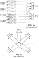
- bi-binaural synthesis consists, with reference to the figure 1a , to filter the signal of the different sound sources S i that it is desired to position, at the restitution, at a position in space, via acoustic transfer functions left HRTF-I and right HRTF-r in the frequency domain corresponding to the appropriate direction, defined in polar coordinates ( ⁇ 1 , ⁇ 1 ).
- the transfer functions HRTF for "Head Related Transfer Functions" in English, are the acoustic transfer functions of the head of the listener between the positions of the space and the auditory canal.
- HRIR for "Head Related Impulse Response” is referred to as their temporal form. These functions may further include a room effect.
- the number of necessary filters or transfer functions is then 2.N for a static binaural synthesis and 4.N for a dynamic binaural synthesis, N designating the number of sound sources or audio streams to be spatialized.
- the binaural filter implementation is generally in the form of two minimal phase filters and a pure delay, corresponding to the difference of the left and right delays applied to the ear furthest away from the source. This delay is usually implemented using a delay line.
- the minimum phase filter is a finite impulse response filter and can be executed in the time or frequency domain. Infinite impulse response filters can be searched to approximate the minimum phase HRTF filter module.
- the sound emanating from the loudspeaker Lf affects the left ear LE through an HRTF filter A but this same sound reaches the right ear RE modified by a HRTF filter B.
- the position of the speakers relative to the aforementioned HB individual may be symmetrical or not.
- Each ear therefore receives the contribution of the 5 loudspeakers in the form modeled below: O ⁇ r ⁇ e ⁇ i ⁇ l ⁇ l ⁇ e boy Wut ⁇ at ⁇ u ⁇ vs ⁇ h ⁇ e
- the filters A, B, C, D and E are modeled, most often, by linear digital filters and it is therefore necessary, in the configuration represented in FIG. figure 1b , 10 filtering functions to be applied, which can be reduced to 5, taking into account the symmetries.
- the aforementioned filtering operations can be performed in the frequency domain, for example by virtue of a fast convolution performed in the Fourier domain.
- a Fast Fourier Transform (FFT) Fourier Transform is then used to perform binauralization effectively.
- the HRTF filters A, B, C, D and E can be simplified as a frequency equalizer and a delay.
- the HRTF filter A can be realized as a simple equalizer, since it is a direct path, while the HRTF filter B includes an additional delay.
- the HRTF filters can be decomposed into a minimum phase filter and a pure delay. The delay for the ear closest to the source can be taken as zero.
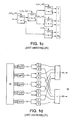
- the spatial decoding reconstruction operation of a 3D audio sound scene, from a reduced number of transmitted channels, as represented in FIG. figure 1c is also known from the state of the art.
- the configuration represented in figure 1c is that relating to the decoding of a coded sound path having location parameters in the frequency domain, in order to reconstruct a spatialized sound scene 5.1.
- the aforementioned reconstruction is carried out by a frequency subband sub-frequency decoder, as represented in FIG. figure 1c .
- the coded audio signal m undergoes 5 spatialization processing steps, which are controlled by parameters or complex coefficients of spatialization CLD and ICC calculated by the encoder and which, by means of decorrelation operations and gain correction, to realistically reconstruct the sound stage composed of six channels, the five channels represented in figure 1b , to which is added a low frequency effect channel Ife.
- a binauralization variant of the sound channels of a spatial decoder can also consist, as represented in FIG. figure 1e , converting each sound channel delivered by the audio decoder into the time domain by a synthesizer "Synth" and then performing the spatial decoding operation and binauralization, or spatialization, in the frequency domain Fourier after transformation by FFT.
- each OTT module corresponding to a matrix of decoding coefficients must then be converted into the Fourier domain, at the cost of an approximation, because the operations are not performed in the same domain.
- the complexity is further increased because the synthetic operation "Synth" is followed by three FFT transformations.
- Another solution may be to perform HRTF filtering directly in the subband domain, as shown in FIG. figure 1f .
- the HRTF filterings are complex to achieve because they require the use of subband filters, the minimum length of which is fixed and which must take into account the phenomenon of spectral folding of the subbands.
- the object of the present invention is to overcome the numerous drawbacks of the above-mentioned prior art of sound spatialization of 3 D audio scenes, in particular transauralisation or binauralization of 3 D audio scenes.
- an objective of the present invention is the execution of a specific filtering of spatially coded audio signals or channels in the frequency subband domain of a spatial decoding, in order to limit the number of transformations two by two, while reducing the filtering operations to a minimum, but maintaining a good quality of source spatialization, including transauralisation or binauralization.
- the execution of the aforementioned specific filtering is based on the equalizer-delay form of the spatialization filters, transaural or binaural, for a direct application of filtering by equalization-delay in the domain of the sub-bands.
- Another objective of the present invention is to obtain a 3D rendering quality very close to that obtained from modeling filters such as original HRTF filters, by the sole addition of a transaural spatial processing of very low complexity, following a classical spatial decoding in the transformed domain.
- an objective of the present invention is a new source spatialization technique applicable not only to the transaural or binaural rendering of a monophonic sound, but also to several monophonic sounds and in particular to the multiple channels of 5.1, 6.1, 7.1, 8.1 or 5.1 stereo sounds. higher.
- the subject of the present invention is thus a method for sound spatialisation of an audio scene comprising a first set comprising a number greater than or equal to the unit of audio channels coded spatially over a number of sub-bands of determined frequencies, and decoded in a transformed domain, in a second set comprising a number greater than or equal to two of sound reproduction channels in the time domain, from acoustic propagation modeling filters of the audio signals of the first set of channels.
- the method which is the subject of the invention is also remarkable in that the filtering by equalization-delay of the signal in sub-band includes at least the application of a phase shift and, if appropriate, a pure delay by storage, for the at least one of the frequency sub-bands.
- the method which is the subject of the invention is also remarkable in that it includes filtering by equalization-delay in a hybrid transformed domain, comprising an additional step of frequency cutting into additional subbands, with or without decimation.
- the method which is the subject of the invention is finally remarkable in that to convert each modeling filter into a gain value or a delay value in the transformed domain, it consists at least in associating as a gain value with each subband a real value. defined as the average of the modeling filter module in this sub-band and to associate as delay value with each sub-band a delay value corresponding to the reception delay between the left ear and the right ear for different positions.
- the subject of the present invention is correspondingly to a sound spatialization device of an audio scene comprising a first set comprising a number, greater than or equal to one, of audio channels coded spatially over a number of sub-bands of determined frequencies, and decoded in a transformed domain into a second set comprising a number greater than or equal to two of time domain rendering sound channels, from sound propagation modeling filters audio signals of the first subset of channels.
- the method and the device which are the subject of the invention are applicable to the electronic industry of audio and / or video hi-fi equipment, to the audio-video game industry, which is executed locally or online.
- the method according to the invention applies to an audio scene such as an audio scene 3 D represented by a first set comprising an N number of audio channels coded spatially greater than or equal to unity, N ⁇ 1, on a number of frequency subbands determined and decoded in a transformed domain.
- the transformed domain is a transformed frequency domain such as Fourier domain, PQMF domain or any hybrid domain derived from them by creating additional frequency subbands, whether or not subjected to a temporal decimation process.
- the spatially coded audio channels constituting the first set N of channels are represented in a nonlimiting manner by the channels Fl, Fr, Sr, Sl, C, Ife previously described in the description and corresponding to a decoding mode of a 3 D audio scene in the corresponding transformed domain, as previously described in the description.
- This mode is none other than the 5.1 mode previously mentioned.
- these signals are decoded in the aforementioned transformed domain according to a determined number of sub-bands suitable for decoding, the set of sub-bands being noted.
- k denotes the rank of the subband considered.
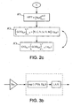
- the method which is the subject of the invention makes it possible to transform all the spatially encoded audio channels mentioned above into a second set comprising a number, greater than or equal to two, of sound reproduction channels in the time domain, the sound reproduction channels being noted Bl and Br for the left binaural channels respectively right, without limitation in the context of the figure 2a . It is understood, in particular, that instead of two binaural channels, the method which is the subject of the invention applies to any number of channels greater than two, allowing, for example, real-time sound reproduction of the 3D audio scene, as represented and described in the description in connection with the figure 1 b.
- this is implemented using acoustic propagation modeling filters of the audio signals of the first set of spatially coded audio channels, taking into account a conversion in the form of at least one gain and delay applicable in the transformed domain, as will be described later in the description.
- the modeling filters will be designated HRTF filters in the following description.
- the method according to the invention consists, for each frequency sub-band of the transformed domain of rank k, to perform a filtering in step A by equalization-delay of the signal in subband by application a gain g k respectively of a delay d k on the sub-band signal, to generate from the spatially-referenced coded channels, that is to say the channels Fl, C, Fr, Sr, Sl and Ife, an equalized and delayed component of a determined delay value in the frequency sub-band SB k of rank k.
- CED kx ⁇ Fl, C, Fr, Sr, Sl, Ife ⁇ (g kx , d kx ).
- FEB kx denotes each equalized and delayed component obtained by applying the gain g kx and the delay d kx to each of the spatially coded audio channels, ie the channels Fl, C, Fr, Sr , Sl, Ife.
- x for the corresponding rank k sub-band, can actually take the values Fl, C, Fr, Sr, Sl, Ile.
- Step A is then followed in the transformed domain of a step B of adding a subset of equalized and delayed components to create a number of filtered signals in the transformed domain corresponding to the number N 'of the second set, greater than or equal to 2, sound channels of restitution in the time domain.
- F ⁇ F1, C, Fr, Sr, S1, Ife ⁇ denotes the subset of the filtered signals in the transformed domain obtained by summation of a subset of equalized and delayed components CED kx .
- the subset of equalized and delayed components may consist of adding five of these components equalized and delayed for each ear to obtain the number N 'equal to 2 of filtered signals in the transformed domain, as will be described in more detail later in the description.
- the aforementioned addition step B is then followed by a step C of synthesizing each of the filtered signals in the transformed domain by a synthesis filter to obtain the second set of number N 'greater than or equal to two of sound signals of restitution in the time domain.
- the method that is the subject of the invention can be applied to any 3D audio scene composed of N varying from 1 to infinity of audio channels or channels coded spatially to N 'varying from 2 to the infinity of sound channels of restitution.
- step B of the figure 2a With regard to the summation step represented in step B of the figure 2a , it is indicated that this consists more specifically of adding a subset of components delayed differently by the different delays to generate the N 'components for each sub-band.
- the filtering by equalization-delay of the signal in sub-band includes at least the application of a phase shift supplemented if necessary by a pure delay by storage, for at least one sub-band. frequency bands.
- the transformed domain may, as previously mentioned in the description, correspond to a hybrid transformed domain as will be described in connection with the figure 2b in the case where no frequency decimation is applied in the corresponding sub-band.
- the delay equalization filtering represented in step A of the figure 2a is then executed in three sub-steps A1, A2, A3 represented at figure 2b .
- the step A comprises an additional step of frequency-cutting in additional sub-bands without decimation, to increase the number of applied gain values and thus the frequency accuracy, followed by a subgrouping step. additional bands to which the aforementioned gain values have been applied.
- Frequency cutting and regrouping operations are represented in substeps A 1 and A 2 of the figure 2b .
- the gain and delay values for the subband of rank k considered are subdivided into Z corresponding gain values, a gain value g kz for each additional subband and at sub-step 1 2 it is understood that the grouping of additional subbands is performed from the corresponding coded audio channels for the corresponding index x which has been applied the gain value g kz in the additional subband considered.
- the sub-step A 2 is then followed by a sub-step A 3 consisting of applying the delay to the grouped additional subbands and in particular to the spatially coded audio channels of corresponding index x via the delay d kx of similar to Step A of Fig. 2a.
- the method which is the subject of the invention can also consist in performing a filtering by equalization-delay in a hybrid transformed domain comprising an additional step of frequency cutting into additional subbands with decimation, as represented in FIG. Figure 2c .
- step A ' 1 of the Figure 2c is identical to step A 1 of the figure 2b , to execute the creation of additional subbands with decimation.
- step A ' 1 of the Figure 2c is executed in the time domain.
- Step A ' 1 is then followed by a step A' 2 corresponding to a grouping of the additional subbands to which the above-mentioned gain values have been applied in view of the decimation.
- Grouping step A ' 2 is itself preceded or followed by the application of the delay dkx thus represented by the double reversing arrow of steps A' 2 and A ' 3 .
- this operation may advantageously consist in associating, as a gain value with each subband of rank k, a real value defined as the average of the corresponding HRTF filter module and to associate, as a delay value with each subband of rank k, a delay value corresponding to the delay of propagation between the left ear and the right ear of a listener for different positions.
- each subband SB k is associated with a delay value corresponding to the propagation delay between the left ear and the right ear of a listener for different positions.
- each band is associated with a real value.
- the HRTF filter module it is possible from the HRTF filter module, to calculate, for each sub-band, the average of the module of the aforementioned HRTF filter. Such an operation is similar to an octave band or Bark analysis of HRTF filters.
- the delay to be applied for the indirect channels that is to say the delay values which are more particularly applicable to the channels whose delay is not minimum, is determined. There are many ways to automatically determine the remaining interaural delays. ITD designated for "I nteraural T ime D ifference" and correspond to the delays between the left and right ears, for different positions of the listener. The threshold method described by S.
- the most common method estimates the arrival time as the time when the HRIR time filter exceeds a given threshold.
- the arrival time may correspond to the time for which the response of the HRIR filter reaches 10% of its maximum.
- the application of a gain in the complex PQMF domain consists in multiplying the value of each sample of the subband signal, represented by a complex value, by the gain value formed by a real number.
- each sub-band SB k of each channel is thus assigned a determined gain.
- the application of a delay in the PQMF transformed domain consists, for each sample of the subband signal represented by a complex value, of introducing a rotation in the complex plane by multiplication of this sample by a complex exponential value depending on the rank of the sub-band considered, the sub-sampling rate in the sub-band considered and a delay parameter related to the interaural delay difference of a listener.
- This pure time delay is a function of the difference in the interaural delay of a listener and the sub-sampling rate in the subband considered.
- the aforementioned delays are applied to the resulting signals, ie the equalized signals and in particular to the subsets of these signals or channels which do not benefit from a direct path.
- the processing implemented therefore consists of performing a complex multiplication between an exponential complex and a subband sample formed by a complex value.
- the method which is the subject of the invention can also be implemented in a hybrid transformed domain.
- This hybrid transformed domain is a frequency domain in which the PQMF bands are advantageously redécoupées by a bank of filters decimated or not.
- the decimation means a decimation in time, so the introduction of a delay advantageously follows the procedure including a pure delay and a phase shifter.
- the delay may be applied only once during the synthesis. It is indeed useless to apply the same delay on each of the branches because the synthesis is a linear operation, without subsampling.
- the method according to the invention is repeated for at least two equalization-delay pairs and the signals obtained are summed to obtain the sound channels in the time domain.
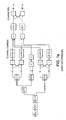
- a more detailed description of a sound spatialization device of an audio scene comprising a first set comprising a number greater than or equal to the unit of audio channels spatially coded on a number of frequency subbands determined and decoded in a domain converted, into a second set comprising a number greater than or equal to 2 of sound reproduction channels in the time domain, according to the subject of the present invention, will now be described in connection with the figures 3a and 3b .
- the device the invention is based on the principle of conversion in the form of at least one gain and a delay applicable in the transformed domain of modeling filters of the acoustic propagation of the audio signals of the first set of channels mentioned above.
- the device according to the invention allows the sound spatialization of an audio scene, such as a 3D audio scene, into a second set comprising a number, greater than or equal to two, of sound reproduction channels in the time domain.
- the device which is the subject of the invention represented in figure 3a relates in a stage of this device specific to each subband SB k of rank k decoding in the transformed domain.
- stage, for each subband of rank k represented in figure 3a is, in fact, replicated for each of the subbands to finally constitute the sound spatialization device according to the subject of the present invention.
- the device that is the subject of the invention as represented on the figure 3a comprises, in addition to the spatial decoder shown, comprising the modules OTT 0 to OTT 4 substantially corresponding to a spatial decoder SD of the prior art as represented in FIG. figure 1c , but in which, in a manner known as such, of the state of the art, a summation of the front channel C and the low frequency channel Ife by an adder S is carried out, an equalization filtering module 1 delay of the signal in subband by applying a gain respectively a delay on the signal in subband.
- the application of a gain is represented on each of the spatially coded audio channels, represented by amplifiers 1 0a to 1 8 , the latter generating an equalized component which may or may not be delayed by means of delay elements noted 1 9 to 1 12 for generating from each of the spatially coded audio channels an equalized and delayed component of a determined delay value in the frequency subband SB k .
- the gains of the amplifiers 1 0 to 1 8 have arbitrary values A, B, B, A, C, D, E, E, D respectively.
- the delay values applied by the delay modules 19 to 12 have the values Df, Bf, Ds, Ds.
- the structure of the gains and delays introduced is symmetrical. A non-symmetrical structure can be implemented without departing from the scope of the subject of the invention.
- the device according to the invention also comprises a module 2 for adding a subset of equalized and delayed components to create a number of filtered signals in the transformed domain corresponding to the number N 'of the second set greater than or equal to two sound channels of restitution in the time domain.
- the device which is the subject of the invention comprises a module 3 for synthesizing each of the filtered signals in the transformed domain to obtain the second set comprising a number N 'greater than or equal to two of sound reproduction signals in the time domain.
- the synthesis module 3 thus comprises, in the embodiment of the figure 3a , A synthesizer 3 0 3 and 1 which each can deliver a sound signal recovery in the time domain B 1 louse left binaural signal, respectively B r for right binaural signal.
- the delays introduced by the delay elements 1 9 , 1 10 , 1 11 and 1 12 are applied to the aforementioned equalized components to generate the equalized and delayed components.
- these delays are applied to the subset that does not benefit from a direct trajectory. These are, in the description of the figure 3a , the signals which have undergone the multiplications by the gains B [k] and E [k] applied by the amplifiers or multipliers 1 1 1 2 and 1 6 and 1 7 .
- the filtering element corresponding, represented in FIG. figure 3b , comprises a numerical multiplier, that is to say one of the multipliers or amplifiers 1 0 to 1 8 and represented by the gain value g kx in FIG. 3b, this multiplier allowing the multiplication of any complex sample of each encoded audio channel of index x corresponding to the channels Fl, Fr, Clfe, Sl, or Sr by a real value, that is to say the gain value previously mentioned in the description.
- the filter element represented in figure 3b includes at least one complex numerical multiplier for introducing a complex-valued rotation of any sample of the subband signal by a complex exponential value, the exp (-j ⁇ (k, SS k )) value where ⁇ (k , SS k ) denotes a phase value which is a function of the sub-sampling rate of the sub-band considered and the rank of the sub-band considered k.
- ⁇ (k, SS k ) ⁇ * ( k +0.5) * d / M.
- the complex numerical multiplier is followed by a delay line denoted by LAR introducing a pure delay of each sample after rotation, making it possible to introduce a pure time delay as a function of the difference in the interaural delay of a listener and the subsampling rate.
- M in the sub-band SB k considered.
- the resulting signals output by the summation modules 2 0 and 2 1 are subsequently passed through the synthesis filter banks 3 3 0 respectively 1 to obtain the binauralisés signals in the time domain B l B r respectively.
- the aforesaid signals can then feed a digital-to-analog converter, in order to allow the listening of sounds left B l and right B r on an audio headset for example.
- the synthesis process performed by the synthesis modules 3 0 3 1 includes, where appropriate, the hybrid synthesis process as described above in the description.
- the method which is the subject of the invention may advantageously consist in dissociating the equalization and delay operations, which may relate to frequency sub-bands in a different number.
- the equalization can for example be performed in the hybrid domain and the delay in the PQMF domain.
- the method and the device that are the subject of the invention can also be applied to effect the trans-scaling, ie the rendering of a 3d sound field on a pair of tops or to convert in an uncomplicated manner a representation of N audio channels or sound sources from a spatial decoder or from several monophonic decoders to N 'available audio channels at the rendering level.
- the filtering operations can then be multiplied if necessary.
- the method and the device which are the subject of the invention can be applied to the case of an interactive 3D game in the sounds emitted by the different objects or sound sources, which can then be spatialized as a function of their relative position in relation to the listener. Sound samples are then compressed and stored in different files or memory areas. To be played and spatialised, they are partially decoded in order to remain in the coded domain and are filtered in the coded domain by suitable binaural filters advantageously using the writing method according to the object of the present invention.
- the invention finally covers a computer program comprising a sequence of instructions stored on a storage medium for execution by a computer or a dedicated sound spatialization device, which during this execution performs the addition filtering and as described in connection with the Figures 2a to 2c and 3a, 3b previously in the description.
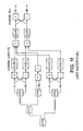
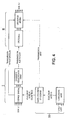
- a first spatial coding and rate reduction coding unit I is considered, including a device that is the subject of the invention as represented in FIG. figure 3a , 3b , making it possible to operate the above-mentioned spatial coding from an audio scene in 5.1 mode for example and the coded audio transmission, on the one hand, and spatial parameters, on the other hand, to a decoding and decoding unit spatial II.
- the calculation of the delay equalization filters can then be performed by a separate unit III, which from the modeling filters, HRTF filters, calculates the gain and delay equalization values and transmits them to the coding unit I. spatial and spatial decoding unit II.
- Spatial coding can thus take into account the HRTFs that will be applied to correct its spatial parameters and improve 3D rendering.
- the rate reduction encoder can use these HRTFs to measure the perceptual effects of frequency quantization.
- the process implemented by the device and method of the invention thus makes it possible to carry out a sound spatialization of an audio scene in which the first set comprises a determined number of spatially coded audio channels and the second set comprises a lower number of sound reproduction channels in the time domain. It also allows decoding to perform an inverse transformation of a number of spatially coded audio channels to a set having a greater or equal number of time domain rendering sound channels.
Landscapes
- Engineering & Computer Science (AREA)
- Physics & Mathematics (AREA)
- Acoustics & Sound (AREA)
- Signal Processing (AREA)
- Multimedia (AREA)
- General Physics & Mathematics (AREA)
- Algebra (AREA)
- Mathematical Analysis (AREA)
- Mathematical Optimization (AREA)
- Mathematical Physics (AREA)
- Pure & Applied Mathematics (AREA)
- Theoretical Computer Science (AREA)
- Stereophonic System (AREA)
Abstract
Description
L'invention est relative à la spatialisation, dite rendu 3D, de signaux audio compressés.The invention relates to the spatialization, known as 3D rendering, of compressed audio signals.
Une telle opération est par exemple exécutée lors de la décompression d'un signal compressé audio 3D par exemple, représenté sur un certain nombre de canaux, vers un nombre de canaux différents, deux par exemple, pour permettre la restitution des effets 3D audio sur un casque d'écoute.Such an operation is for example performed during the decompression of a compressed 3D audio signal for example, represented on a number of channels, to a number of different channels, two for example, to allow the reproduction of the 3D audio effects on a headphones.
Ainsi, le terme « binaural » vise la restitution sur un casque stéréophonique d'un signal sonore avec néanmoins des effets de spatialisation. L'invention ne se limite toutefois pas à la technique précitée et s'applique, notamment, à des techniques dérivées du « binaural », telles que les techniques de restitution dites techniques TRANSAURAL® , c'est-à-dire sur des haut-parleurs distants. TRANSAURAL® est une marque de commerce déposée par la société COOPER BAUCK CORPORATION. De telles techniques peuvent alors utiliser une « annulation de diaphonie » (« cross-talk cancellation » en anglais), laquelle consiste à annuler les chemins acoustiques croisés, de manière à ce qu'un son, ainsi traité puis émis par les haut-parleurs, puisse n'être perçu que par une seule des deux oreilles d'un auditeur.Thus, the term "binaural" refers to the reproduction on a stereophonic headphones of a sound signal with nevertheless spatialization effects. The invention is however not limited to the aforementioned technique and applies, in particular, to techniques derived from the "binaural", such as the so-called technical rendering techniques TRANSAURAL ® , that is to say on top of remote speakers. TRANSAURAL ® is a registered trademark of COOPER BAUCK CORPORATION. Such techniques can then use a "cross-talk cancellation", which consists in canceling the crossed acoustic paths, so that a sound, thus processed and then emitted by the loudspeakers , can be perceived only by one of the two ears of a listener.
En conséquence, l'invention est également relative à la transmission et à la restitution de signaux audio multicanaux et à leur conversion vers un dispositif de restitution, transducteur, imposé par l'équipement d'un utilisateur. C'est par exemple le cas pour la restitution d'une scène sonore 5.1 par un casque d'écoute audio, ou par une paire de hauts parleurs.Accordingly, the invention also relates to the transmission and reproduction of multichannel audio signals and their conversion to a rendering device, transducer, imposed by the equipment of a user. This is for example the case for the reproduction of a 5.1 sound stage by an audio headset, or by a pair of loudspeakers.
L'invention est également relative à la restitution, dans le cadre d'un jeu ou enregistrement vidéo par exemple, d'un ou plusieurs échantillons sonores stockés dans des fichiers, en vue de leur spatialisation.The invention also relates to the reproduction, in the context of a game or video recording for example, of one or more samples sound stored in files, with a view to their spatialization.
Parmi les techniques connues dans le domaine de la spatialisation sonore binaurale, différentes approches ont été proposées.Among the known techniques in the field of binaural sound spatialization, different approaches have been proposed.
Un procédé de spatialisation sonore du genre indiqué dans le préambule de la revendication 1 ci-dessous est décrit dans la demande de brevet
En particulier, la synthèse binaurale bicanale consiste, en référence à la
On obtient, pour chaque source sonore Si deux signaux gauche et droit qui sont alors additionnés aux signaux gauche et droit issus de la spatialisation des autres sources sonores, pour donner finalement les signaux L et R diffusés aux oreilles gauche et droite de l'auditeur.For each sound source S i, two left and right signals are obtained which are then added to the left and right signals from the spatialization of the other sound sources, to finally give the signals L and R diffused to the left and right ears of the listener. .
Le nombre de filtres, ou fonctions de transfert, nécessaires est alors 2.N pour une synthèse binaurale statique et 4.N pour une synthèse binaurale dynamique, N désignant le nombre de sources sonore ou de flux audio à spatialiser.The number of necessary filters or transfer functions is then 2.N for a static binaural synthesis and 4.N for a dynamic binaural synthesis, N designating the number of sound sources or audio streams to be spatialized.
Des travaux intitulés
Ainsi, pour une fonction de transfert HRTF exprimée sous la forme : ![]()
![]()
ϕ retard (f) = 2πfτ correspond au retard interaural ;
ϕmin(f)= H(log(|H(f)|)) est la phase minimale associée au module du filtre H.Thus, for an HRTF transfer function expressed as form: ![]()
![]()
φ delay (f) = 2πfτ corresponds to the interaural delay;
φmin (f) = H ( log (| H (f ) |)) is the minimum phase associated with the H filter module.
L'implémentation des filtres binauraux se fait, en général, sous la forme de deux filtres à phase minimale et d'un retard pur, correspondant à la différence des retards gauche et droit appliqués à l'oreille la plus éloignée de la source. Ce retard est en général implémenté à l'aide d'une ligne à retard.The binaural filter implementation is generally in the form of two minimal phase filters and a pure delay, corresponding to the difference of the left and right delays applied to the ear furthest away from the source. This delay is usually implemented using a delay line.
Le filtre à phase minimale est un filtre à réponse impulsionnelle finie et peut être exécuté dans le domaine temporel ou fréquentiel. Des filtres à réponse impulsionnelle infinie peuvent être recherchés pour approximer le module des filtres HRTF à phase minimale.The minimum phase filter is a finite impulse response filter and can be executed in the time or frequency domain. Infinite impulse response filters can be searched to approximate the minimum phase HRTF filter module.
En ce qui concerne la binauralisation, on se place, en référence à la
Cinq haut-parleurs C : Centre, Lf : Left front, Rf : Right front, SI : Surround left, Sr : Surround right, produisent chacun un son qui est perçu par l'être humain HB sur les deux récepteurs que sont ses oreilles. On modélise les transformations subies par le son par une fonction de filtrage représentant la modification que ce son subit lors de sa propagation entre le haut-parleur qui restitue ce son et une oreille donnée.Five loudspeakers C: between C, Lf: L is NLOR f, R f: R f ight NLOR, SI: S urround l eft, Sr: S urround r ight, each produce a sound that is perceived by the human HB on the two receivers that are his ears. The transformations undergone by the sound are modeled by a filtering function representing the modification that this sound undergoes during its propagation between the speaker which reproduces this sound and a given ear.
En particulier, le son émanant du haut-parleur Lf affecte l'oreille gauche LE au travers d'un filtre HRTF A mais ce même son atteint l'oreille droite RE modifié par un filtre HRTF B.In particular, the sound emanating from the loudspeaker Lf affects the left ear LE through an HRTF filter A but this same sound reaches the right ear RE modified by a HRTF filter B.
La position des haut-parleurs par rapport à l'individu HB précités peut être symétrique ou non.The position of the speakers relative to the aforementioned HB individual may be symmetrical or not.
Chaque oreille reçoit donc la contribution des 5 haut-parleurs sous la forme modélisée ci-après : ![]()
![]()
où BI est le signal binauralisé pour l'oreille gauche LE et Br est le signal binauralisé pour l'oreille droite RE.Each ear therefore receives the contribution of the 5 loudspeakers in the form modeled below: ![]()
![]()
where BI is the binauralized signal for the left ear LE and Br is the binauralized signal for the right ear RE.
Les filtres A, B, C, D et E sont modélisés, le plus souvent, par des filtres numériques linéaires et il faut donc, dans la configuration représentée en
De manière connue en tant que telle, les opérations de filtrage précitées peuvent être réalisées dans le domaine fréquentiel, par exemple grâce à une convolution rapide exécutée dans le domaine de Fourier. On utilise alors une transformée de Fourier rapide FFT, pour « Fast Fourier Transform » en anglais, pour exécuter la binauralisation de façon efficace.In a manner known per se, the aforementioned filtering operations can be performed in the frequency domain, for example by virtue of a fast convolution performed in the Fourier domain. A Fast Fourier Transform (FFT) Fourier Transform is then used to perform binauralization effectively.
Les filtres HRTF A, B, C, D et E peuvent être simplifiés sous la forme d'un égaliseur en fréquence et d'un retard. Le filtre HRTF A peut être réalisé sous la forme d'un simple égaliseur, car il s'agit d'une trajectoire directe, alors que le filtre HRTF B inclut un retard supplémentaire. De manière classique les filtres HRTF peuvent être décomposés en un filtre à phase minimale et un retard pur. Le retard pour l'oreille la plus proche de la source peut être pris égal à zéro.The HRTF filters A, B, C, D and E can be simplified as a frequency equalizer and a delay. The HRTF filter A can be realized as a simple equalizer, since it is a direct path, while the HRTF filter B includes an additional delay. Conventionally the HRTF filters can be decomposed into a minimum phase filter and a pure delay. The delay for the ear closest to the source can be taken as zero.
L'opération de reconstruction par décodage spatial d'une scène sonore 3D audio, à partir d'un nombre réduit de canaux transmis, telle que représentée en
La reconstruction précitée est effectuée par un décodeur spatial par sous-bandes fréquentielles, tel que représenté en
Lorsque l'on souhaite procéder à une binauralisation des canaux sonores issus d'un décodeur spatial tel que représenté en
En référence au schéma précité, il apparaît nécessaire de réaliser la transformation des canaux sonores dont on dispose dans le domaine temporel, avant de procéder à la binauralisation du signal. Cette opération de retour dans le domaine temporel est symbolisée par les blocs synthétiseurs « Synth » qui exécutent l'opération de transformation fréquence-temps pour chacun des canaux issus du décodeur spatial (SD). Le filtrage par filtres HRTF peut ensuite être réalisé par les filtres A, B, C, D, E, avec ou sans application du schéma égalisé, correspondant à un filtrage classique.With reference to the aforementioned scheme, it appears necessary to perform the transformation of the sound channels available in the time domain before proceeding to the binauralization of the signal. This return operation in the time domain is symbolized by the synth synthesizer blocks that execute the frequency-time transformation operation for each of the channels coming from the spatial decoder (SD). The filtering by HRTF filters can then be performed by the filters A, B, C, D, E, with or without applying the equalized scheme, corresponding to a conventional filtering.
Une variante de binauralisation des canaux sonores d'un décodeur spatial peut consister également, ainsi que représenté en
Dans cette hypothèse, chaque module OTT correspondant à une matrice de coefficients de décodage, doit alors être converti dans le domaine de Fourier, au prix d'une approximation, car les opérations ne sont pas effectuées dans le même domaine. En outre, la complexité est encore accrue, car l'opération de synthèse « Synth » est suivie de trois transformations FFT.In this case, each OTT module corresponding to a matrix of decoding coefficients, must then be converted into the Fourier domain, at the cost of an approximation, because the operations are not performed in the same domain. In addition, the complexity is further increased because the synthetic operation "Synth" is followed by three FFT transformations.
Ainsi, pour binauraliser une scène sonore issue d'un décodeur spatial, il n'existe guère d'autre possibilité que de réaliser :
- soit 6 transformations temps-fréquence, si l'on veut réaliser la binauralisation en dehors du décodeur spatial ;
- soit une opération de synthèse suivie de 3 transformations de Fourier, FFT, si l'on veut réaliser l'opération dans le domaine FFT.
- or 6 time-frequency transformations, if binauralization is to be carried out outside the space decoder;
- either a synthesis operation followed by 3 Fourier transforms, FFT, if one wishes to carry out the operation in the FFT domain.
A la rigueur, une autre solution peut consister à effectuer le filtrage HRTF directement dans le domaine des sous-bandes, ainsi que représenté en
Toutefois, dans cette hypothèse, les filtrages HRTF sont complexes à réaliser, car ces derniers imposent l'utilisation de filtres en sous-bandes, dont la longueur minimale est fixée et qui doivent prendre en compte le phénomène de repliement spectral des sous-bandes.However, in this case, the HRTF filterings are complex to achieve because they require the use of subband filters, the minimum length of which is fixed and which must take into account the phenomenon of spectral folding of the subbands.
L'économie introduite par la réduction d'opérations de transformation est compensée négativement par l'explosion du nombre d'opérations nécessaires pour le filtrage, en raison de l'exécution de ces opérations dans le domaine PQMF pour Pseudo Quadrature Mirror Filter en anglais.The economy introduced by the reduction of transformation operations is negatively offset by the explosion in the number of operations required for filtering, because of the execution of these operations in the PQMF domain for P seudo Q uadrature M irror F Ilter in English.
La présente invention a pour objectif de remédier aux nombreux inconvénients des techniques antérieures précitées de spatialisation sonore des scènes audio 3 D, notamment de transauralisation ou de binauralisation de scènes audio 3 D.The object of the present invention is to overcome the numerous drawbacks of the above-mentioned prior art of sound spatialization of 3 D audio scenes, in particular transauralisation or binauralization of 3 D audio scenes.
En particulier, un objectif de la présente invention est l'exécution d'un filtrage spécifique de signaux ou canaux audio codés spatialement dans le domaine des sous-bandes fréquentielles d'un décodage spatial, afin de limiter le nombre de transformations deux à deux, tout en réduisant les opérations de filtrage au minimum, mais en conservant une bonne qualité de spatialisation source, notamment en transauralisation ou binauralisation.In particular, an objective of the present invention is the execution of a specific filtering of spatially coded audio signals or channels in the frequency subband domain of a spatial decoding, in order to limit the number of transformations two by two, while reducing the filtering operations to a minimum, but maintaining a good quality of source spatialization, including transauralisation or binauralization.
Selon un aspect particulièrement remarquable de la présente invention, l'exécution du filtrage spécifique précité s'appuie sur la mise sous forme égaliseur-retard des filtres de spatialisation, transaurale ou binaurale, pour une application directe d'un filtrage par égalisation-retard dans le domaine des sous-bandes.According to a particularly remarkable aspect of the present invention, the execution of the aforementioned specific filtering is based on the equalizer-delay form of the spatialization filters, transaural or binaural, for a direct application of filtering by equalization-delay in the domain of the sub-bands.
Un autre objectif de la présente invention est l'obtention d'une qualité de rendu 3 D très proche de celle obtenue à partir de filtres de modélisation tels que des filtres HRTF d'origine, par la seule adjonction d'un traitement spatial transaural de très basse complexité, suite à un décodage spatial classique dans le domaine transformé.Another objective of the present invention is to obtain a 3D rendering quality very close to that obtained from modeling filters such as original HRTF filters, by the sole addition of a transaural spatial processing of very low complexity, following a classical spatial decoding in the transformed domain.
Un objectif de la présente invention est enfin une nouvelle technique de spatialisation source applicable non seulement au rendu transaural ou binaural d'un son monophonique, mais également à plusieurs sons monophoniques et notamment aux canaux multiples de sons stéréo 5.1, 6.1, 7.1, 8.1 ou supérieurs.Finally, an objective of the present invention is a new source spatialization technique applicable not only to the transaural or binaural rendering of a monophonic sound, but also to several monophonic sounds and in particular to the multiple channels of 5.1, 6.1, 7.1, 8.1 or 5.1 stereo sounds. higher.
La présente invention a ainsi pour objet un procédé de spatialisation sonore d'une scène audio comportant un premier ensemble comprenant un nombre supérieur ou égal à l'unité de canaux audio codés spatialement sur un nombre de sous-bandes de fréquences déterminé, et décodés dans un domaine transformé, en un deuxième ensemble comprenant un nombre supérieur ou égal à deux de canaux sonores de restitution dans le domaine temporel, à partir de filtres de modélisation de la propagation acoustique des signaux audio du premier ensemble de canaux.The subject of the present invention is thus a method for sound spatialisation of an audio scene comprising a first set comprising a number greater than or equal to the unit of audio channels coded spatially over a number of sub-bands of determined frequencies, and decoded in a transformed domain, in a second set comprising a number greater than or equal to two of sound reproduction channels in the time domain, from acoustic propagation modeling filters of the audio signals of the first set of channels.
Conformément à l'invention ce procédé est remarquable en ce que, pour chaque filtre de modélisation converti sous forme d'au moins un gain et d'un retard applicables dans le domaine transformé, il consiste à effectuer au moins, pour chaque sous-bande fréquentielle du domaine transformé :
- un filtrage par égalisation-retard du signal en sous-bande, par application d'un gain respectivement d'un retard sur le signal en sous-bande, pour engendrer à partir des canaux codés spatialement, une composante égalisée et retardée d'une valeur déterminée dans la sous-bande fréquentielle considérée,
- une addition d'un sous-ensemble de composantes égalisées et retardées, pour créer un nombre de signaux filtrés dans le domaine transformé correspondant au nombre du deuxième ensemble, supérieur ou égal à deux, de canaux sonores de restitution dans le domaine temporel,
- une synthèse de chacun des signaux filtrés dans le domaine transformé par un filtre de synthèse, pour obtenir le deuxième ensemble de nombre supérieur ou égal à deux de signaux sonores de restitution dans le domaine temporel.
- a filtering by equalization-delay of the signal in sub-band, by applying a gain respectively of a delay on the signal in sub-band, to generate from the spatially coded channels, an equalized and delayed component of a value determined in the frequency subband considered,
- an addition of a subset of equalized and delayed components, to create a number of filtered signals in the transformed domain corresponding to the number of the second set, greater than or equal to two, of sound channels of restitution in the time domain,
- a synthesis of each of the filtered signals in the transformed domain by a synthesis filter, to obtain the second set of numbers greater than or equal to two of sound signals of restitution in the time domain.
Le procédé objet de l'invention est également remarquable en ce que le filtrage par égalisation-retard du signal en sous-bande inclut au moins l'application d'un déphasage et le cas échéant d'un retard pur par mémorisation, pour l'une au moins des sous-bandes de fréquences.The method which is the subject of the invention is also remarkable in that the filtering by equalization-delay of the signal in sub-band includes at least the application of a phase shift and, if appropriate, a pure delay by storage, for the at least one of the frequency sub-bands.
Le procédé objet de l'invention est également remarquable en ce qu'il inclut un filtrage par égalisation-retard dans un domaine transformé hybride, comportant une étape supplémentaire de découpe en fréquence en sous-bandes supplémentaires, avec ou sans décimation.The method which is the subject of the invention is also remarkable in that it includes filtering by equalization-delay in a hybrid transformed domain, comprising an additional step of frequency cutting into additional subbands, with or without decimation.
Le procédé objet de l'invention est enfin remarquable en ce que pour convertir chaque filtre de modélisation en une valeur de gain respectivement de retard dans le domaine transformé, il consiste au moins à associer comme valeur de gain à chaque sous-bande une valeur réelle définie comme la moyenne du module du filtre de modélisation dans cette sous-bande et à associer comme valeur de retard à chaque sous-bande une valeur de retard correspondant au retard de réception entre l'oreille gauche et l'oreille droite pour différentes positions.The method which is the subject of the invention is finally remarkable in that to convert each modeling filter into a gain value or a delay value in the transformed domain, it consists at least in associating as a gain value with each subband a real value. defined as the average of the modeling filter module in this sub-band and to associate as delay value with each sub-band a delay value corresponding to the reception delay between the left ear and the right ear for different positions.
La présente invention a corrélativement pour objet un dispositif de spatialisation sonore d'une scène audio comportant un premier ensemble comprenant un nombre, supérieur ou égal à l'unité, de canaux audio codés spatialement sur un nombre de sous-bandes de fréquences déterminé, et décodés dans un domaine transformé, en un deuxième ensemble comportant un nombre supérieur ou égal à deux de canaux sonores de restitution dans le domaine temporel, à partir de filtres de modélisation de la propagation acoustique signaux audio du premier sous-ensemble de canaux.The subject of the present invention is correspondingly to a sound spatialization device of an audio scene comprising a first set comprising a number, greater than or equal to one, of audio channels coded spatially over a number of sub-bands of determined frequencies, and decoded in a transformed domain into a second set comprising a number greater than or equal to two of time domain rendering sound channels, from sound propagation modeling filters audio signals of the first subset of channels.
Conformément à l'invention ce dispositif est remarquable en ce que, pour chaque sous-bande fréquentielle d'un décodeur spatial dans le domaine transformé, ce dispositif comprend outre ce décodeur spatial :
- un module de filtrage par égalisation-retard du signal en sous-bande par application d'un gain respectivement d'un retard sur le signal en sous-bande, pour engendrer à partir de chacun des canaux audio-codés spatialement une composante égalisée et retardée d'une valeur de retard déterminée dans la sous-bande de fréquences considérée,
- un module d'addition d'un sous-ensemble de composantes égalisées et retardées pour créer un nombre de signaux filtrés dans le domaine transformé correspondant au nombre du deuxième ensemble supérieur ou égal à deux des canaux sonores de restitution dans le domaine temporel,
- un module de synthèse de chacun des signaux filtrés dans le domaine transformé pour obtenir le deuxième ensemble comprenant un nombre supérieur ou égal à deux des canaux sonores de restitution dans le domaine temporel.
- a filtering module by equalizing-delaying the signal in the sub-band by applying a gain respectively of a delay on the signal in sub-band, for generating from each of the spatially audio-coded channels an equalized and delayed component a delay value determined in the sub-frequency band considered,
- a module for adding a subset of equalized and delayed components to create a number of filtered signals in the transformed domain corresponding to the number of the second set greater than or equal to two of the time domain rendering sound channels,
- a synthesis module of each of the filtered signals in the transformed domain to obtain the second set comprising a number greater than or equal to two of the sound reproduction channels in the time domain.
Le procédé et le dispositif objets de l'invention trouvent application à l'industrie électronique des appareils audio et/ou vidéo à haute fidélité, à l'industrie des jeux audio-vidéo exécutés localement ou en ligne.The method and the device which are the subject of the invention are applicable to the electronic industry of audio and / or video hi-fi equipment, to the audio-video game industry, which is executed locally or online.
Ils seront mieux compris à la lecture de la description et à l'observation des dessins ci-après dans lesquels, outre les
- la
figure 2a représente un organigramme illustratif des étapes de mise en oeuvre du procédé de spatialisation sonore objet de l'invention ; - la figuré 2b représente à titre illustratif, une variante de mise en oeuvre du procédé objet de l'invention représenté en
figure 2a , obtenu par création de sous-bandes supplémentaires, en l'absence de décimation ; - la
figure 2c représente à titre illustratif, une variante de mise en oeuvre du procédé objet de l'invention représenté enfigure 2a obtenu par création de sous-bandes supplémentaires, en présence de décimation ; - la
figure 3a représente, à titre illustratif, un étage, pour une sous-bande de fréquences d'un décodeur spatial, d'un dispositif de spatialisation sonore objets de l'invention ; - la
figure 3b représente, à titre illustratif, un détail de mise en oeuvre d'un filtre par égalisation-retard permettant la mise en oeuvre du dispositif objet de l'invention représenté enfigure 3a ; - la
figure 4 représente à titre illustratif, un exemple de mise en oeuvre du dispositif objet de l'invention dans lequel le calcul des filtres d'égalisation retard est délocalisé.
- the
figure 2a represents an illustrative flow diagram of the implementation steps of the sound spatialization method which is the subject of the invention; - FIG. 2b represents, by way of illustration, an alternative embodiment of the method which is the subject of the invention represented in FIG.
figure 2a obtained by creating additional subbands, in the absence of decimation; - the
Figure 2c represents, by way of illustration, an alternative embodiment of the process which is the subject of the invention represented infigure 2a obtained by creating additional subbands in the presence of decimation; - the
figure 3a represents, by way of illustration, a stage, for a frequency sub-band of a spatial decoder, of a sound spatialization device which is the subject of the invention; - the
figure 3b represents, by way of illustration, a detail of implementation of a filter by equalization-delay allowing the implementation of the device object of the invention represented infigure 3a ; - the
figure 4 represents for illustrative purposes, an example of implementation of the device according to the invention in which the calculation of the delay equalization filters is delocalized.
Une description plus détaillée du procédé de spatialisation sonore d'une scène audio conforme à l'objet de la présente invention sera maintenant donnée en liaison avec la
Le procédé objet de l'invention s'applique à une scène audio telle qu'une scène audio 3 D représentée par un premier ensemble comprenant un nombre N de canaux audio codés spatialement supérieur ou égal à l'unité, N ≥ 1, sur un nombre de sous-bandes de fréquences déterminé et décodé dans un domaine transformé.The method according to the invention applies to an audio scene such as an audio scene 3 D represented by a first set comprising an N number of audio channels coded spatially greater than or equal to unity, N ≥ 1, on a number of frequency subbands determined and decoded in a transformed domain.
Le domaine transformé s'entend d'un domaine fréquentiel transformé tel que domaine de Fourier, domaine PQMF ou de tout domaine hybride issu de ces derniers par création de sous-bandes de fréquences supplémentaires, soumises ou non à un processus de décimation temporel.The transformed domain is a transformed frequency domain such as Fourier domain, PQMF domain or any hybrid domain derived from them by creating additional frequency subbands, whether or not subjected to a temporal decimation process.
En conséquence, les canaux audio codés spatialement constitutifs du premier ensemble N de canaux, sont représentés de manière non limitative par les canaux Fl, Fr, Sr, Sl, C, Ife précédemment décrits dans la description et correspondant à un mode de décodage d'une scène audio 3 D dans le domaine transformé correspondant, ainsi que décrit précédemment dans la description. Ce mode n'est autre que le mode 5.1 précédemment mentionné.Consequently, the spatially coded audio channels constituting the first set N of channels, are represented in a nonlimiting manner by the channels Fl, Fr, Sr, Sl, C, Ife previously described in the description and corresponding to a decoding mode of a 3 D audio scene in the corresponding transformed domain, as previously described in the description. This mode is none other than the 5.1 mode previously mentioned.
En outre, ces signaux sont décodés dans le domaine transformé précité selon un nombre de sous-bandes déterminé propres au décodage, l'ensemble des sous-bandes étant noté ![]()
k désigne le rang de la sous-bande considérée.In addition, these signals are decoded in the aforementioned transformed domain according to a determined number of sub-bands suitable for decoding, the set of sub-bands being noted. ![]()
k denotes the rank of the subband considered.
Le procédé objet de l'invention permet de transformer l'ensemble des canaux audio codés spatialement précédemment cités en un deuxième ensemble comportant un nombre, supérieur ou égal à deux, de canaux sonores de restitution dans le domaine temporel, les canaux sonores de restitution étant notés Bl et Br pour les canaux binauraux gauche respectivement droit, de manière non limitative dans le cadre de la
Selon un aspect remarquable du procédé objet de l'invention, celui-ci est mis en oeuvre à partir de filtres de modélisation de la propagation acoustique des signaux audio du premier ensemble de canaux audio codés spatialement, compte tenu d'une conversion sous forme d'au moins un gain et d'un retard applicables dans le domaine transformé, ainsi qu'il sera décrit ultérieurement dans la description. De manière non limitative, les filtres de modélisation seront désignés filtres HRTF dans la suite de la description.According to a remarkable aspect of the method which is the subject of the invention, this is implemented using acoustic propagation modeling filters of the audio signals of the first set of spatially coded audio channels, taking into account a conversion in the form of at least one gain and delay applicable in the transformed domain, as will be described later in the description. Without limitation, the modeling filters will be designated HRTF filters in the following description.
La conversion précitée est notée pour chaque filtre HRTF considéré pour une sous-bande SBk de rang k à établir une valeur de gain gk et de retard dk correspondant, la conversion précédente étant alors notée, ainsi que représentée en
Compte tenu de la conversion précitée, le procédé objet de l'invention consiste, pour chaque sous-bande fréquentielle du domaine transformé de rang k, à effectuer un filtrage à l'étape A par égalisation-retard du signal en sous-bande par application d'un gain gk respectivement d'un retard dk sur le signal en sous-bande, pour engendrer à partir des canaux codés spatialement précités, c'est-à-dire les canaux Fl, C, Fr, Sr, Sl et Ife, une composante égalisée et retardée d'une valeur de retard déterminée dans la sous-bande de fréquence SBk considérée de rang k.Given the aforementioned conversion, the method according to the invention consists, for each frequency sub-band of the transformed domain of rank k, to perform a filtering in step A by equalization-delay of the signal in subband by application a gain g k respectively of a delay d k on the sub-band signal, to generate from the spatially-referenced coded channels, that is to say the channels Fl, C, Fr, Sr, Sl and Ife, an equalized and delayed component of a determined delay value in the frequency sub-band SB k of rank k.
Sur la
Dans la relation symbolique précitée, FEBkx désigne chaque composante égalisée et retardée obtenue par application du gain gkx et du retard dkx sur chacun des canaux audio codés spatialement, c'est-à-dire les canaux Fl, C, Fr, Sr, Sl, Ife.In the aforementioned symbolic relation, FEB kx denotes each equalized and delayed component obtained by applying the gain g kx and the delay d kx to each of the spatially coded audio channels, ie the channels Fl, C, Fr, Sr , Sl, Ife.
En conséquence et dans la relation symbolique précitée, x, pour la sous-bande de rang k correspondant, peut prendre en fait les valeurs Fl, C, Fr, Sr, Sl, Ile.Accordingly, and in the aforementioned symbolic relationship, x, for the corresponding rank k sub-band, can actually take the values Fl, C, Fr, Sr, Sl, Ile.
L'étape A est alors suivie dans le domaine transformé d'une étape B d'addition d'un sous-ensemble de composantes égalisées et retardées pour créer un nombre de signaux filtrés dans le domaine transformé correspondant au nombre N' du deuxième ensemble, supérieur ou égal à 2, de canaux sonores de restitution dans le domaine temporel.Step A is then followed in the transformed domain of a step B of adding a subset of equalized and delayed components to create a number of filtered signals in the transformed domain corresponding to the number N 'of the second set, greater than or equal to 2, sound channels of restitution in the time domain.
A l'étape B de la ![]()
![]()
Dans la relation symbolique précitée, F{Fl, C, Fr, Sr, Sl, Ife} désigne le sous-ensemble des signaux filtrés dans le domaine transformé obtenu par sommation d'un sous-ensemble de composantes égalisées et retardées CEDkx.In the aforementioned symbolic relation, F {F1, C, Fr, Sr, S1, Ife} denotes the subset of the filtered signals in the transformed domain obtained by summation of a subset of equalized and delayed components CED kx .
A titre d'exemple non limitatif et pour fixer les idées, pour un premier ensemble comportant un nombre de canaux audio codés spatialement N = 6, correspondant à un mode 5.1, le sous-ensemble de composantes égalisées et retardées peut consister à additionner cinq de ces composantes égalisées et retardées pour chaque oreille pour obtenir le nombre N' égal à 2 de signaux filtrés dans le domaine transformé, ainsi qu'il sera décrit de manière plus détaillée ultérieurement dans la description.By way of nonlimiting example and to fix the ideas, for a first set comprising a number of spatially coded audio channels N = 6, corresponding to a mode 5.1, the subset of equalized and delayed components may consist of adding five of these components equalized and delayed for each ear to obtain the number N 'equal to 2 of filtered signals in the transformed domain, as will be described in more detail later in the description.
L'étape d'addition B précitée est alors suivie d'une étape C de synthèse de chacun des signaux filtrés dans le domaine transformé par un filtre de synthèse pour obtenir le deuxième ensemble de nombre N' supérieur ou égal à deux de signaux sonores de restitution dans le domaine temporel.The aforementioned addition step B is then followed by a step C of synthesizing each of the filtered signals in the transformed domain by a synthesis filter to obtain the second set of number N 'greater than or equal to two of sound signals of restitution in the time domain.
A l'étape C de la ![]()
![]()
D'une manière générale, on indique que le procédé objet de l'invention peut être appliqué à toute scène 3D audio composée de N variant de 1 à l'infini de voies ou canaux audio codés de façon spatiale vers N' variant de 2 à l'infini de canaux sonores de restitution.In general, it is indicated that the method that is the subject of the invention can be applied to any 3D audio scene composed of N varying from 1 to infinity of audio channels or channels coded spatially to N 'varying from 2 to the infinity of sound channels of restitution.
En ce qui concerne l'étape de sommation représentée à l'étape B de la
De manière plus spécifique, on indique que le filtrage par égalisation-retard du signal en sous-bande inclut au moins l'application d'un déphasage complété le cas échéant par un retard pur par mémorisation, pour l'une au moins des sous-bandes de fréquence.More specifically, it is indicated that the filtering by equalization-delay of the signal in sub-band includes at least the application of a phase shift supplemented if necessary by a pure delay by storage, for at least one sub-band. frequency bands.
La notion d'application d'un retard pur est symbolisée à l'étape A de la
Le domaine transformé peut, ainsi que mentionné précédemment dans la description, correspondre à un domaine transformé hybride ainsi qu'il sera décrit en liaison avec la
En référence à la
Dans ces conditions, l'étape A comporte une étape supplémentaire de découpe en fréquence en sous-bandes supplémentaires sans décimation, pour augmenter le nombre de valeurs de gain appliquées et ainsi la précision en fréquence, suivie d'une étape de regroupement de sous-bandes supplémentaires, auxquelles ont été appliquées les valeurs de gain précitées.Under these conditions, the step A comprises an additional step of frequency-cutting in additional sub-bands without decimation, to increase the number of applied gain values and thus the frequency accuracy, followed by a subgrouping step. additional bands to which the aforementioned gain values have been applied.
Les opérations de découpe en fréquence puis de regroupement sont représentées aux sous-étapes A1 et A2 de la
L'étape des découpes en fréquence est représentée à la sous-étape A1 par la relation : ![]()
![]()
L'étape de regroupement est représentée à la sous-étape A2 par la relation : ![]()
![]()
A la sous-étape A1. on comprend que les valeurs de gain et de retard pour la sous-bande de rang k considérée sont subdivisées en Z valeurs de gain correspondantes, une valeur de gain gkz pour chaque sous-bande supplémentaire et à la sous-étape 12 on comprend que le regroupement des sous-bandes supplémentaires est effectué à partir des canaux audio codés correspondants pour l'indice x correspondant auquel a été appliqué la valeur de gain gkz dans la sous-bande supplémentaire considérée.In the substep A 1. it is understood that the gain and delay values for the subband of rank k considered are subdivided into Z corresponding gain values, a gain value g kz for each additional subband and at
Dans la relation précédente ![]()
![]()
La sous-étape A2 est alors suivie d'une sous-étape A3 consistant à appliquer le retard aux sous-bandes supplémentaires regroupées et en particulier aux canaux audio codés spatialement d'indice x correspondant par l'intermédiaire du retard dkx de manière semblable à l'étape A de la figue 2a.The sub-step A 2 is then followed by a sub-step A 3 consisting of applying the delay to the grouped additional subbands and in particular to the spatially coded audio channels of corresponding index x via the delay d kx of similar to Step A of Fig. 2a.
L'opération correspondante est notée par la relation : ![]()
![]()
En outre, le procédé objet de l'invention peut consister également à effectuer un filtrage par égalisation-retard dans un domaine transformé hybride comportant une étape supplémentaire de découpe de fréquence en sous-bandes supplémentaires avec décimation, ainsi que représentée en
Dans cette hypothèse, l'étape A'1 de la
Dans cette hypothèse, l'opération de décimation à l'étape A'1 de la
L'étape A'1 est alors suivie d'une étape A'2 correspondant à un regroupement des sous-bandes supplémentaires auxquelles ont été appliquées les valeurs de gain précitées compte tenu de la décimation.Step A ' 1 is then followed by a step A' 2 corresponding to a grouping of the additional subbands to which the above-mentioned gain values have been applied in view of the decimation.
L'étape A'2 de regroupement est elle-même précédée ou suivie de l'application du retard dkx ainsi représentée par la double flèche d'interversion des étapes A'2 et A'3.Grouping step A ' 2 is itself preceded or followed by the application of the delay dkx thus represented by the double reversing arrow of steps A' 2 and A ' 3 .
On comprend, en particulier, que lorsque l'application du retard est effectuée antérieurement au regroupement, le retard est appliqué directement sur les signaux des sous-bandes supplémentaires antérieurement au regroupement.It is understood, in particular, that when the application of the delay is performed prior to the grouping, the delay is applied directly to the signals of the additional subbands prior to the grouping.
En ce qui concerne la conversion de chaque filtre HRTF en une valeur de gain et de retard dans le domaine transformé, cette opération peut consister, avantageusement, à associer, comme valeur de gain à chaque sous-bande de rang k, une valeur réelle définie comme la moyenne du module du filtre HRTF correspondant et à associer, comme valeur de retard à chaque sous-bande de rang k, une valeur de retard correspondant au retard de propagation entre l'oreille gauche et l'oreille droite d'un auditeur pour différentes positions.With regard to the conversion of each HRTF filter into a gain and delay value in the transformed domain, this operation may advantageously consist in associating, as a gain value with each subband of rank k, a real value defined as the average of the corresponding HRTF filter module and to associate, as a delay value with each subband of rank k, a delay value corresponding to the delay of propagation between the left ear and the right ear of a listener for different positions.
Ainsi, à partir d'un filtre HRTF, il est possible de calculer de façon automatique les gains et les délais de retard appliqués en sous-bande. A partir de la résolution fréquentielle du banc de filtre HRTF, on associe à chacune des sous-bandes SBk une valeur de retard correspondant au retard de propagation entre l'oreille gauche et l'oreille droite d'un auditeur pour différentes positions.Thus, from an HRTF filter, it is possible to automatically calculate the gains and delay times applied in subband. From the frequency resolution of the HRTF filter bank, each subband SB k is associated with a delay value corresponding to the propagation delay between the left ear and the right ear of a listener for different positions.
Ainsi, à partir d'un filtre HRTF, on peut calculer de façon automatique les gains et les délais de retard à appliquer en sous-bande.Thus, from an HRTF filter, one can automatically calculate the gains and delay times to be applied in subband.
A partir de la résolution fréquentielle du banc de filtre, on associe à chacune des bandes une valeur réelle. A titre d'exemple non limitatif, il est possible à partir du module du filtre HRTF, de calculer, pour chaque sous-bande, la moyenne du module du filtre HRTF précité. Une telle opération est similaire à une analyse en bande d'octave ou de Bark des filtres HRTF. De même, on détermine le retard à appliquer pour les canaux indirects, c'est-à-dire les valeurs de retard qui sont applicables plus particulièrement aux canaux dont le retard n'est pas minimum. Il existe de nombreuses méthodes pour déterminer de manière automatique les retards interauraux encore désignés ITD pour « Interaural Time Difference » et qui correspondent aux retards entre l'oreille gauche et l'oreille droite, pour différentes positions de l'auditeur. On peut utiliser, à titre d'exemple non limitatif, la méthode du seuil décrite par S. Busson dans la thèse de doctorat de l'Université de la Méditerranée Est-Marseille II, 2006, intitulée « Individualisation d'indices acoustiques pour la synthèse binaurale ». Le principe des méthodes d'estimation du retard interaural de type seuil est de déterminer le temps d'arrivée, ou encore le retard initial de l'onde sur l'oreille droite Td et sur l'oreille gauche Tg. Le retard interaural est donné par la relation ITD seuil = Td - Tg.From the frequency resolution of the filter bank, each band is associated with a real value. By way of nonlimiting example, it is possible from the HRTF filter module, to calculate, for each sub-band, the average of the module of the aforementioned HRTF filter. Such an operation is similar to an octave band or Bark analysis of HRTF filters. Similarly, the delay to be applied for the indirect channels, that is to say the delay values which are more particularly applicable to the channels whose delay is not minimum, is determined. There are many ways to automatically determine the remaining interaural delays. ITD designated for "I nteraural T ime D ifference" and correspond to the delays between the left and right ears, for different positions of the listener. The threshold method described by S. Busson in the doctoral dissertation of the Université de la Mediterranée Est-Marseille II, 2006 entitled " Individualization of acoustic indices for synthesis" can be used as a non-limiting example. binaural ". The principle of methods for estimating threshold-type interaural delay is to determine the arrival time, or the initial delay of the wave on the right ear Td and on the left ear Tg. Interaural delay is given by the relation ITD threshold = Td - Tg.
La méthode la plus courante estime le temps d'arrivée comme l'instant où le filtre temporel HRIR dépasse un seuil donné. Par exemple le temps d'arrivée peut correspondre au temps pour lequel la réponse du filtre HRIR atteint 10 % de son maximum.The most common method estimates the arrival time as the time when the HRIR time filter exceeds a given threshold. For example, the arrival time may correspond to the time for which the response of the HRIR filter reaches 10% of its maximum.
Un exemple de mise en oeuvre spécifique dans le domaine transformé PQMF sera maintenant donné ci-après.An example of a specific implementation in the PQMF transformed domain will now be given below.
D'une manière générale, on indique que l'application d'un gain dans le domaine PQMF complexe consiste à multiplier la valeur de chaque échantillon du signal en sous-bande, représenté par une valeur complexe, par la valeur de gain formée par un nombre réel.In general, it is indicated that the application of a gain in the complex PQMF domain consists in multiplying the value of each sample of the subband signal, represented by a complex value, by the gain value formed by a real number.
En effet, il est bien connu que l'usage d'un domaine transformé PQMF complexe, permet d'appliquer les gains en s'affranchissant des problèmes de repliement de spectre engendrés par le sous- échantillonnage inhérent aux bancs de filtres. Chaque sous-bande SBk de chaque canal se voit ainsi affectée d'un gain déterminé.Indeed, it is well known that the use of a complex PQMF transformed domain makes it possible to apply the gains while avoiding the problems of aliasing caused by the subsampling inherent in the filterbanks. Each sub-band SB k of each channel is thus assigned a determined gain.
En outre, l'application d'un retard dans le domaine transformé PQMF consiste au moins, pour chaque échantillon du signal en sous-bande, représenté par une valeur complexe, à introduire une rotation dans le plan complexe par multiplication de cet échantillon par une valeur exponentielle complexe fonction du rang de la sous-bande considérée, du taux de sous-échantillonnage dans la sous-bande considérée et d'un paramètre de retard lié à la différence de retard interaural d'un auditeur.In addition, the application of a delay in the PQMF transformed domain consists, for each sample of the subband signal represented by a complex value, of introducing a rotation in the complex plane by multiplication of this sample by a complex exponential value depending on the rank of the sub-band considered, the sub-sampling rate in the sub-band considered and a delay parameter related to the interaural delay difference of a listener.
La rotation dans le plan complexe est alors suivie d'un retard temporel pur de l'échantillon après rotation. Ce retard temporel pur est une fonction de la différence du retard interaural d'un auditeur et du taux de sous échantillonnage dans la sous-bande considérée.The rotation in the complex plane is then followed by a pure time delay of the sample after rotation. This pure time delay is a function of the difference in the interaural delay of a listener and the sub-sampling rate in the subband considered.
De manière pratique, on indique que les retards précités sont appliqués sur les signaux résultants c'est-à-dire les signaux égalisés et en particulier sur les sous-ensembles de ces signaux ou canaux qui ne bénéficient pas d'une trajectoire directe.In practice, it is indicated that the aforementioned delays are applied to the resulting signals, ie the equalized signals and in particular to the subsets of these signals or channels which do not benefit from a direct path.
En particulier, la rotation est effectuée sous la forme d'une multiplication complexe par une valeur exponentielle de la forme : ![]()
et par un retard pur implémenté par une ligne à retard, par exemple réalisant l'opération : ![]()
![]()
and by a pure delay implemented by a delay line, for example carrying out the operation: ![]()
Dans les relations précédentes :
- exp est la fonction exponentielle ;
- j est tel que j*j = -1 ;
- k le rang de la sous-bande SBk considérée ;
- M est le taux de sous-échantillonnage dans la sous-bande considérée, M veut être pris égal à 64, par exemple ;
- y(k, n) est la valeur de l'échantillon de sortie après application du retard pur sur l'échantillon temporel de rang n de la sous-bande SBk de rang k, c'est-à-dire l'échantillon x (k,n) auquel est appliqué le retard B.
- d et D dans les relations précédentes sont tels qu'ils correspondent à l'application d'un retard de D*M + d dans le domaine temporel non sous-échantillonné. Le retard D*M + d correspond au retard interaural calculé précédemment. d peut prendre des valeurs négatives ce qui permet de simuler une avance de phase en lieu et place d'un retard.
- exp is the exponential function;
- j is such that j * j = -1;
- k the rank of the SBk sub-band considered;
- M is the sub-sampling rate in the sub-band considered, M wants to be taken equal to 64, for example;
- y (k, n) is the value of the output sample after application of the pure delay on the n-rank time sample of sub-band SB k of rank k, i.e. sample x (k, n) to which the delay B is applied.
- d and D in the previous relations are such that they correspond to the application of a delay of D * M + d in the non-subsampled time domain. The delay D * M + d corresponds to the interaural delay calculated previously. d can take negative values which makes it possible to simulate a phase advance instead of a delay.
L'opération ainsi réalisée induit une approximation qui est convenable pour l'effet recherché.The operation thus performed induces an approximation which is suitable for the desired effect.
En terme d'opérations de calcul, le traitement mis en oeuvre consiste donc à réaliser une multiplication complexe entre une exponentielle complexe et d'un échantillon en sous-bande formé par une valeur complexe.In terms of calculation operations, the processing implemented therefore consists of performing a complex multiplication between an exponential complex and a subband sample formed by a complex value.
Un retard éventuel, si le retard total à appliquer est supérieur à la valeur M, est à insérer, mais cette opération ne comporte pas d'opération arithmétique.A possible delay, if the total delay to be applied is greater than the value M, is to be inserted, but this operation does not involve any arithmetic operation.
Le procédé objet de l'invention peut également être mis en oeuvre dans un domaine transformé hybride. Ce domaine transformé hybride est un domaine fréquentiel dans lequel les bandes PQMF sont avantageusement redécoupées par un banc de filtres décimé ou non.The method which is the subject of the invention can also be implemented in a hybrid transformed domain. This hybrid transformed domain is a frequency domain in which the PQMF bands are advantageously redécoupées by a bank of filters decimated or not.
Si le banc de filtres est décimé, la décimation s'entendant d'une décimation en temps, alors l'introduction d'un retard suit avantageusement la procédure incluant un retard pur et un déphaseur.If the filter bank is decimated, the decimation means a decimation in time, so the introduction of a delay advantageously follows the procedure including a pure delay and a phase shifter.
Si le banc de filtre n'est pas décimé, alors le retard peut n'être appliqué qu'une seule fois lors de la synthèse. Il est en effet inutile d'appliquer le même retard sur chacune des branches car la synthèse est une opération linéaire, sans sous-échantillonneur.If the filter bank is not decimated, then the delay may be applied only once during the synthesis. It is indeed useless to apply the same delay on each of the branches because the synthesis is a linear operation, without subsampling.
L'application des gains reste identique, ceux-ci étant simplement plus nombreux, ainsi que décrit précédemment en liaison avec la
Enfin, selon une variante de mise en oeuvre, l'on réitère le procédé selon l'invention pour au moins deux couples égalisation-retard et l'on somme les signaux obtenus pour obtenir les canaux sonores dans le domaine temporel.Finally, according to an alternative embodiment, the method according to the invention is repeated for at least two equalization-delay pairs and the signals obtained are summed to obtain the sound channels in the time domain.
Une description plus détaillée d'un dispositif de spatialisation sonore d'une scène audio comportant un premier ensemble comprenant un nombre supérieur ou égal à l'unité de canaux audio codés spatialement sur un nombre de sous-bandes de fréquence déterminé et décodé dans un domaine transformé, en un deuxième ensemble comprenant un nombre supérieur ou égal à 2 de canaux sonores de restitution dans le domaine temporel, conforme à l'objet de la présente invention, sera maintenant décrit en liaison avec les
Ainsi que mentionné précédemment, le dispositif objet de l'invention est basé sur le principe de la conversion sous forme d'au moins un gain et d'un retard applicable dans le domaine transformé de filtres de modélisation de la propagation acoustique des signaux audio du premier ensemble de canaux précité. Le dispositif objet de l'invention permet la spatialisation sonore d'une scène audio, telle qu'une scène audio 3D, en un deuxième ensemble comportant un nombre, supérieur ou égal à deux, de canaux sonores de restitution dans le domaine temporel.As mentioned above, the device the invention is based on the principle of conversion in the form of at least one gain and a delay applicable in the transformed domain of modeling filters of the acoustic propagation of the audio signals of the first set of channels mentioned above. The device according to the invention allows the sound spatialization of an audio scene, such as a 3D audio scene, into a second set comprising a number, greater than or equal to two, of sound reproduction channels in the time domain.
Le dispositif objet de l'invention représenté en
On comprend en particulier que l'étage, pour chaque sous-bande de rang k représenté en
Par convention, l'étage représenté en
En référence à la figure précitée, le dispositif objet de l'invention tel que représenté sur la
Sur la
En référence à la
Le dispositif objet de l'invention comporte également un module 2 d'addition d'un sous-ensemble de composantes égalisées et retardées pour créer un nombre de signaux filtrés dans le domaine transformé correspondant au nombre N' du deuxième ensemble supérieur ou égal à deux de canaux sonores de restitution dans le domaine temporel.The device according to the invention also comprises a
Enfin le dispositif objet de l'invention comporte un module 3 de synthèse de chacun des signaux filtrés dans le domaine transformé pour obtenir le deuxième ensemble comprenant un nombre N' supérieur ou égal à deux de signaux sonores de restitution dans le domaine temporel. Le module de synthèse 3 comporte ainsi, dans le mode de réalisation de la
Les composantes égalisées et retardées dans le mode de réalisation de la
- A[k] désignant le gain des amplificateurs 10, 13 pour la sous-bande SBk de rang k,
- B[k] désigne le gain de l'amplificateur 11, 12 représenté en
figure 3a , - C[k] désigne le gain de l'amplificateur 14,
- D[k] désigne le gain des amplificateurs 15 18,
- E[K] désigne le gain des amplificateurs 16 17.
- A [k] denoting the gain of the
amplifiers - B [k] denotes the gain of the
amplifier figure 3a , - C [k] denotes the gain of the
amplifier 1 4 , - D [k] denotes the gain of the
amplifiers 1 5 1 8, - E [K] denotes the gain of
amplifiers 1 6 1 7 .
en ce qui concerne les canaux audio codés spatialement et en particulier ces canaux Fl, Fr, Clfe, SI et Sr pour la sous-bande SBk, on désigne par FI[k][n], Fr[k][n], Fc[k][n], Ife[k][n], Sl[k][n], Sr[k][n], le enième échantillon de la sous-bande SBk. Ainsi chaque amplificateur, 10 à 18 délivre les composantes égalisées suivantes successivement :
- A[k]*Fl[k][n],
- B[k]*Fl[k][n],
- B[k]*Fr[k][n],
- A[k]*Fr[k][n],
- C[k]*Fc[k][n],
- D[k]*Sl[k][n],
- E[k]*Sl[k][n],
- E[k]*Sr[k][n],
- D[k]*Sr[k][n].
- A [k] * Fl [k] [n]
- B [k] * Fl [k] [n]
- B [k] * En [k] [n]
- A [k] * En [k] [n]
- C [k] * Fc [k] [n],
- D [k] * Sl [k] [n]
- E [k] * Sl [k] [n],
- E [k] * Sr [k] [n],
- D [k] * Sr [k] [n].
Les opérations précédentes, ainsi que mentionné précédemment dans la description, sont réalisées sous la forme d'une multiplication réelle agissant dans ce cas sur des nombres complexes.The foregoing operations, as previously mentioned in the description, are realized in the form of a real multiplication acting in this case on complex numbers.
Les retards introduits par les éléments de retard 19, 110, 111 et 112 sont appliqués sur les composantes égalisées précitées pour engendrer les composantes égalisées et retardées.The delays introduced by the
Dans l'exemple représenté en
Une description plus détaillée d'un filtre ou élément de filtrage par égalisation-retard constitué par exemple par un amplificateur multiplicateur 11 et un élément retardateur 19 sera maintenant donnée en liaison avec la
En ce qui concerne l'application du gain, on indique que l'élément de filtrage, correspondant, représenté en
En outre, l'élément de filtrage représenté en
Dans un mode de réalisation ϕ(k,SSk) = ϕ*(k+0.5)*d/M.In one embodiment φ (k, SS k ) = φ * ( k +0.5) * d / M.
Le multiplicateur numérique complexe est suivi d'une ligne à retard notée L.A.R. introduisant un retard pur de chaque échantillon après rotation, permettant d'introduire un retard temporel pur fonction de la différence du retard interaural d'un auditeur et du taux de sous-échantillonnage M dans la sous-bande SBk considérée.The complex numerical multiplier is followed by a delay line denoted by LAR introducing a pure delay of each sample after rotation, making it possible to introduce a pure time delay as a function of the difference in the interaural delay of a listener and the subsampling rate. M in the sub-band SB k considered.
Ainsi, la ligne à retard L.A.R. permet d'introduire le retard sur l'échantillon complexe après rotation de la forme y(k, n) = x(k, n-D).Thus, the delay line L.A.R. allows to introduce the delay on the complex sample after rotation of the form y (k, n) = x (k, n-D).
Enfin, on indique que les valeurs de d et D sont telles que ces valeurs correspondent à l'application d'un retard D*M+d dans le domaine temporel non échantillonné et que le retard D*M+d correspond au retard interaural précédemment mentionné.Finally, it is indicated that the values of d and D are such that these values correspond to the application of a delay D * M + d in the non-sampled time domain and that the delay D * M + d corresponds to the interaural delay previously mentionned.
Pour la mise en oeuvre du dispositif objet de l'invention, tel que représenté en
Pour obtenir les canaux sonores de restitution dans le domaine temporel, à savoir les canaux Bl gauche respectivement Br droit représentés en
- L0[k][n]+L1[k][n]+L2[k][n]+L3[k][n]+L4[k][n] pour
le module sommateur 20, et - R0[k][n]+R1[k][n]+R2[k][n]+R3[k][n]+R4[k][n] pour
le module sommateur 21.
- L0 [k] [n] + L1 [k] [n] + L2 [k] [n] + L3 [k] [n] + L4 [k] [n] for the summing module 20 , and
- R0 [k] [n] + R1 [k] [n] + R2 [k] [n] + R3 [k] [n] + R4 [k] [n] for the summing
module 2 1 .
Les signaux résultants délivrés par les modules de sommation 20 et 21 sont ensuite passés dans les bancs de filtres de synthèse 30 respectivement 31 afin d'obtenir les signaux binauralisés dans le domaine temporel Bl respectivement Br.The resulting signals output by the
Les signaux précités peuvent ensuite alimenter un convertisseur numérique-analogique, afin de permettre l'écoute des sons gauche Bl et droit Br sur un casque d'écoute audio par exemple.The aforesaid signals can then feed a digital-to-analog converter, in order to allow the listening of sounds left B l and right B r on an audio headset for example.
L'opération de synthèse réalisée par les modules de synthèse 30 et 31 inclut, le cas échéant, l'opération de synthèse hybride telle que décrite précédemment dans la description.The synthesis process performed by the synthesis modules 3 0 3 1 includes, where appropriate, the hybrid synthesis process as described above in the description.
Le procédé objet de l'invention peut avantageusement consister à dissocier les opérations d'égalisation et de retard, lesquelles peuvent porter sur des sous-bandes de fréquence en nombre différent. En variante, l'égalisation peut par exemple être effectuée dans le domaine hybride et le retard dans le domaine PQMF.The method which is the subject of the invention may advantageously consist in dissociating the equalization and delay operations, which may relate to frequency sub-bands in a different number. Alternatively, the equalization can for example be performed in the hybrid domain and the delay in the PQMF domain.
On comprend que le procédé et le dispositif objets de l'invention bien que décrits pour la binauralisation de six canaux vers un casque d'écoute peuvent également s'appliquer pour effectuer la transauralisation, c'est-à-dire la restitution d'un champ sonore 3D sur une paire de hauts parleurs ou pour convertir de façon peu complexe une représentation de N canaux audio ou sources sonores issus d'un décodeur spatial ou de plusieurs décodeurs monophoniques vers N' canaux audio disponibles au niveau de la restitution. Les opérations de filtrages peuvent alors être à multiplier le cas échéant.It will be understood that the method and the device that are the subject of the invention, although described for binauralising six channels to a headset, can also be applied to effect the trans-scaling, ie the rendering of a 3d sound field on a pair of tops or to convert in an uncomplicated manner a representation of N audio channels or sound sources from a spatial decoder or from several monophonic decoders to N 'available audio channels at the rendering level. The filtering operations can then be multiplied if necessary.
A titre d'exemple complémentaire non limitatif, le procédé et le dispositif objets de l'invention peuvent être appliqués au cas d'un jeu 3D interactif dans les sons émis par les différents objets ou sources sonores, lesquels peuvent alors être spatialisés en fonction de leur position relative par rapport à l'auditeur. Des échantillons sonores sont alors compressés et stockés dans différents fichiers ou différentes zones mémoires. Pour être joués et spatialisés, ils sont partiellement décodés afin de rester dans le domaine codé et sont filtrés dans le domaine codé par des filtres binauraux adéquats de manière avantageuse en utilisant le procédé d'écrit conformément à l'objet de la présente invention.By way of nonlimiting complementary example, the method and the device which are the subject of the invention can be applied to the case of an interactive 3D game in the sounds emitted by the different objects or sound sources, which can then be spatialized as a function of their relative position in relation to the listener. Sound samples are then compressed and stored in different files or memory areas. To be played and spatialised, they are partially decoded in order to remain in the coded domain and are filtered in the coded domain by suitable binaural filters advantageously using the writing method according to the object of the present invention.
En effet, en regroupant les opérations de décodage et de spatialisation, la complexité globale du processus est fortement réduite sans toutefois entraîner de perte de qualité.Indeed, by grouping the decoding and spatialization operations, the overall complexity of the process is greatly reduced without causing loss of quality.
L'invention couvre enfin un programme d'ordinateur comportant une suite d'instructions mémorisées sur un support de mémorisation pour exécution par un ordinateur ou un dispositif dédié de spatialisation sonore, lequel lors de cette exécution, exécute les étapes de filtrage d'addition et de synthèse telles que décrite en liaison avec les
On comprend en particulier que les opérations représentées aux figures précitées peuvent avantageusement être mises en oeuvre sur des échantillons numériques complexes par l'intermédiaire d'une unité centrale de traitement, d'une mémoire de travail et d'une mémoire de programme, non représentées au dessin de la
Enfin, le calcul des gains et des retards constituant les filtres d'égalisation-retard peut être exécuté de manière externe au dispositif objet de l'invention représenté en
En référence à la figure précitée, on considère une première unité de codage spatial et de codage à réduction de débit I, incluant un dispositif objet de l'invention tel que représenté en
Le calcul des filtres d'égalisation retard peut alors être effectué par une unité distincte III, laquelle à partir des filtres de modélisation, filtres HRTF, calcule les valeurs d'égalisation de gain et de retard et les transmet à l'unité I de codage spatial et à l'unité II de décodage spatial.The calculation of the delay equalization filters can then be performed by a separate unit III, which from the modeling filters, HRTF filters, calculates the gain and delay equalization values and transmits them to the coding unit I. spatial and spatial decoding unit II.
Le codage spatial peut ainsi prendre en compte les HRTF qui seront appliquées pour corriger ses paramètres spatiaux et améliorer le rendu 3D. De même le codeur à réduction de débit pourra se servir de ces HRTF pour mesurer les effets perceptifs d'une quantification en fréquence.Spatial coding can thus take into account the HRTFs that will be applied to correct its spatial parameters and improve 3D rendering. Similarly, the rate reduction encoder can use these HRTFs to measure the perceptual effects of frequency quantization.
Côté décodage ce sont les HRTF transmises qui seront appliquées dans le décodeur spatial, et permettront le cas échéant de reconstruire les voies restituées.On the decoding side, it is the transmitted HRTFs that will be applied in the space decoder, and will enable the reconstruction of the restored channels if necessary.
Comme dans les exemples précédents, ce sont 2 voies à partir de 5 qui seront restituées, mais d'autres cas peuvent inclure la construction de 5 voies à partir de 3 comme illustré ci-dessus. Le procédé de décodage spatial procédera alors comme suit :
- projection des 3 canaux reçus sur un ensemble de canaux virtuels (supérieur aux 5 de sortie) en utilisant les informations spatiales (upmix) ;
- réduction des canaux virtuels aux 5 canaux de sortie en utilisant les HRTF.
- projection of the 3 received channels on a set of virtual channels (greater than the 5 of output) by using the spatial information (upmix);
- reducing the virtual channels to the 5 output channels using the HRTFs.
Si les HRTF ont été appliquées au codeur, alors on pourra éventuellement supprimer leur contribution avant upmix pour réaliser le schéma ci-dessus.If the HRTFs have been applied to the encoder, then their contribution before upmix may be removed to achieve the above scheme.
Les HRTF après conversion sous leur forme gain / retard, peuvent être quantifiées de façon privilégiées sous la forme suivante : codage en différentiel de leurs valeurs puis quantification de leurs différences : si on appel G[k] les valeurs des gains de l'égaliseur, alors on transmettra les valeurs quantifiées : ![]()
linéairement ou logarithmiquement.The HRTF after conversion in their gain / delay form, can be quantified in a privileged way in the following form: differential coding of their values then quantification of their differences: if we call G [k] the values of the gains of the equalizer, then we will transmit the quantified values: ![]()
linearly or logarithmically.
De manière plus spécifique en référence à la
Claims (17)
- Method of sound spatialization of an audio scene comprising a first set, having a number, greater than or equal to unity, of audio channels spatially coded on a determined number of frequency sub-bands and decoded in a transformed domain, into a second set having a number greater than or equal to two of sound reproduction channels in the time domain, on the basis of filters for modelling the acoustic propagation of the audio signals of said first set of channels, characterized in that, for each modelling filter converted into the form of at least one gain and one delay which are applicable in said transformed domain, said method includes at least, for each frequency sub-band of said transformed domain:- the filtering by equalization-delay of the sub-band signal by applying a gain respectively a delay to said sub-band signal, so as to produce, on the basis of the spatially coded channels, an equalized component delayed by a determined delay value in the frequency sub-band considered;- the addition of a subset of equalized and delayed components, so as to create a number of filtered signals in the transformed domain corresponding to the number of said second set greater than or equal to two of sound reproduction channels in the time domain;- the synthesis of each of the filtered signals in the transformed domain by a synthesis filter, so as to obtain said second set in number greater than or equal to two of sound reproduction channels in the time domain.
- Method according to Claim 1, characterized in that said filtering by equalization-delay of the sub-band signal includes at least the application of a phase shift for one at least of the frequency sub-bands.
- Method according to Claim 2, characterized in that said filtering by equalization-delay furthermore includes a pure delay by storage for one at least of the frequency sub-bands.
- Method according to one of Claims 1 to 3, characterized in that said filtering by equalization-delay in a hybrid transformed domain, comprises an additional step of frequency splitting into additional sub-bands without decimation, so as to increase the number of gain values applied, followed by a step of grouping said additional sub-bands to which said gain values have been applied, and then of applying said delay.
- Method according to one of Claims 1 to 3, characterized in that said filtering by equalization-delay in a hybrid transformed domain comprises an additional step of frequency splitting into additional sub-bands with decimation, so as to increase the number of gain values applied, followed by a step of grouping said additional sub-bands to which said gain values have been applied, said grouping step itself being preceded or followed by the application of said delay.
- Method according to one of the preceding claims, characterized in that, to convert each modelling filter into a value of gain respectively of delay in the transformed domain, the latter consists at least in:- associating as gain value with each sub-band a real value defined as the mean of the modulus of the modelling filter;- associating as delay value with each sub-band a delay value corresponding to the propagation delay between the left ear and the right ear for various positions.
- Method according to one of Claims 1 to 3 or 6, with the exclusion of Claims 4 or 5, characterized in that the application of a gain in the PQMF domain consists in multiplying the value of each sample of the sub-band signal, represented by a complex value, by the gain value formed by a real number.
- Method according to one of Claims 1 to 3 or 6 or 7, with the exclusion of Claims 4 or 5, characterized in that the application of a delay in the PQMF transformed domain consists at least, for each sample of the sub-band signal, represented by a complex value, in:- introducing a rotation in the complex plane by multiplying this sample by a complex exponential value dependent on the rank of the sub-band considered, on the rate of sub-sampling in the sub-band considered, and on a delay parameter related to the difference in interaural delay of a listener;- introducing a pure time delay of the sample after rotation, said pure time delay being a function of the difference of the interaural delay of a listener and of the rate of sub-sampling in the sub-band considered.
- Method according to one of Claims 1 to 8, characterized in that for a binaural sound spatialization of an audio scene in which the first set comprises a number of spatially coded audio channels equal to N=6, in 5.1 mode, said second set comprises two sound reproduction channels in the time domain, for playback by an audio headset.
- Method according to one of Claims 1 to 9, characterized in that the method is repeated for at least two equalization-delay pairs and the signals obtained are summed so as to obtain the sound channels in the time domain.
- Method according to one of Claims 1 to 9, characterized in that for a sound spatialization of an audio scene in which the first set comprises a determined number of spatially coded audio channels and the second set comprises a lesser number of sound reproduction channels in the time domain, this method consists, on decoding, in performing an inverse transformation of a number of spatially coded audio channels to a set comprising a higher or equal number of sound reproduction channels in the time domain.
- Method according to one of the preceding claims, characterized in that the gain and delay values associated with the modelling filter are transmitted in quantized form.
- Device for the sound spatialization of an audio scene comprising a first set, having a number, greater than or equal to unity, of audio channels spatially coded on a determined number of frequency sub-bands and decoded in a transformed domain, into a second set having a number greater than or equal to two of sound reproduction channels in the time domain, on the basis of filters for modelling the acoustic propagation of the audio signals of said first set of channels, characterized in that, for each frequency sub-band of a spatial decoder, in the transformed domain, said device comprises, in addition to this spatial decoder:- means for the filtering by equalization-delay of the sub-band signal by applying at least one gain respectively one delay to said sub-band signal, so as to produce, on the basis of each of the spatially coded audio channels an equalized component delayed by a determined delay value in the frequency sub-band considered;- means for adding a subset of equalized and delayed components, so as to create a number of filtered signals in the transformed domain corresponding to the number of said second set greater than or equal to two of sound reproduction channels in the time domain;- means for the synthesis of each of the filtered signals in the transformed domain, so as to obtain said second set having a number greater than or equal to two of sound playback signals in the time domain.
- Device according to Claim 13, characterized in that said means for filtering by applying a gain comprise a digital multiplier of any complex sample of each spatially coded audio channel by a real value.
- Device according to Claim 13 or 14, characterized in that said means for filtering by applying a delay comprise at least one complex digital multiplier, making it possible to introduce a rotation in the complex plane of any sample of the sub-band signal by a complex exponential value, dependent on the rank of the sub-band considered, on the rate of sub-sampling in the sub-band considered and on a delay parameter related to the difference in interaural delay of a listener.
- Device according to Claim 15, characterized in that said filtering means furthermore comprise a pure delay line of each sample after rotation, making it possible to introduce a pure time delay dependent on the difference of the interaural delay of a listener and of the sub-sampling rate in the sub-band considered.
- Computer program comprising a series of instructions stored on a storage medium for execution by a computer or a dedicated device, characterized in that during this execution, said program executes the filtering, addition and synthesis steps according to one of Claims 1 to 12.
Priority Applications (1)
| Application Number | Priority Date | Filing Date | Title |
|---|---|---|---|
| PL07731710T PL2000002T3 (en) | 2006-03-28 | 2007-03-08 | Method and device for efficient binaural sound spatialization in the transformed domain |
Applications Claiming Priority (2)
| Application Number | Priority Date | Filing Date | Title |
|---|---|---|---|
| FR0602685A FR2899423A1 (en) | 2006-03-28 | 2006-03-28 | Three-dimensional audio scene binauralization/transauralization method for e.g. audio headset, involves filtering sub band signal by applying gain and delay on signal to generate equalized and delayed component from each of encoded channels |
| PCT/FR2007/050894 WO2007110519A2 (en) | 2006-03-28 | 2007-03-08 | Method and device for efficient binaural sound spatialization in the transformed domain |
Publications (2)
| Publication Number | Publication Date |
|---|---|
| EP2000002A2 EP2000002A2 (en) | 2008-12-10 |
| EP2000002B1 true EP2000002B1 (en) | 2009-08-05 |
Family
ID=37649439
Family Applications (1)
| Application Number | Title | Priority Date | Filing Date |
|---|---|---|---|
| EP07731710A Active EP2000002B1 (en) | 2006-03-28 | 2007-03-08 | Method and device for efficient binaural sound spatialization in the transformed domain |
Country Status (12)
| Country | Link |
|---|---|
| US (1) | US8605909B2 (en) |
| EP (1) | EP2000002B1 (en) |
| JP (1) | JP5090436B2 (en) |
| KR (1) | KR101325644B1 (en) |
| CN (1) | CN101455095B (en) |
| AT (1) | ATE439013T1 (en) |
| BR (1) | BRPI0709276B1 (en) |
| DE (1) | DE602007001877D1 (en) |
| ES (1) | ES2330274T3 (en) |
| FR (1) | FR2899423A1 (en) |
| PL (1) | PL2000002T3 (en) |
| WO (1) | WO2007110519A2 (en) |
Families Citing this family (27)
| Publication number | Priority date | Publication date | Assignee | Title |
|---|---|---|---|---|
| KR101218776B1 (en) * | 2006-01-11 | 2013-01-18 | 삼성전자주식회사 | Method of generating multi-channel signal from down-mixed signal and computer-readable medium |
| US8027479B2 (en) * | 2006-06-02 | 2011-09-27 | Coding Technologies Ab | Binaural multi-channel decoder in the context of non-energy conserving upmix rules |
| ES2399562T3 (en) * | 2006-10-13 | 2013-04-02 | Auro Technologies | Method and encoder for combining digital data sets, method for decoding and decoder for such combined digital data sets and recording medium for storing such combined digital data sets |
| KR101464977B1 (en) * | 2007-10-01 | 2014-11-25 | 삼성전자주식회사 | Memory management method, and method and apparatus for decoding multi-channel data |
| KR100954385B1 (en) * | 2007-12-18 | 2010-04-26 | 한국전자통신연구원 | 3D audio signal processing apparatus and method using personalized head transfer function, and high-reality multimedia playback system using the same |
| FR2938947B1 (en) * | 2008-11-25 | 2012-08-17 | A Volute | PROCESS FOR PROCESSING THE SIGNAL, IN PARTICULAR AUDIONUMERIC. |
| FR2969804A1 (en) * | 2010-12-23 | 2012-06-29 | France Telecom | IMPROVED FILTERING IN THE TRANSFORMED DOMAIN. |
| KR101828448B1 (en) * | 2012-07-27 | 2018-03-29 | 프라운호퍼 게젤샤프트 쭈르 푀르데룽 데어 안겐반텐 포르슝 에. 베. | Apparatus and method for providing a loudspeaker-enclosure-microphone system description |
| US10068579B2 (en) * | 2013-01-15 | 2018-09-04 | Electronics And Telecommunications Research Institute | Encoding/decoding apparatus for processing channel signal and method therefor |
| CN104010264B (en) * | 2013-02-21 | 2016-03-30 | 中兴通讯股份有限公司 | The method and apparatus of binaural audio signal process |
| KR102159990B1 (en) * | 2013-09-17 | 2020-09-25 | 주식회사 윌러스표준기술연구소 | Method and apparatus for processing multimedia signals |
| US9067135B2 (en) | 2013-10-07 | 2015-06-30 | Voyetra Turtle Beach, Inc. | Method and system for dynamic control of game audio based on audio analysis |
| US10063982B2 (en) | 2013-10-09 | 2018-08-28 | Voyetra Turtle Beach, Inc. | Method and system for a game headset with audio alerts based on audio track analysis |
| US9716958B2 (en) | 2013-10-09 | 2017-07-25 | Voyetra Turtle Beach, Inc. | Method and system for surround sound processing in a headset |
| US9143878B2 (en) * | 2013-10-09 | 2015-09-22 | Voyetra Turtle Beach, Inc. | Method and system for headset with automatic source detection and volume control |
| US9338541B2 (en) | 2013-10-09 | 2016-05-10 | Voyetra Turtle Beach, Inc. | Method and system for in-game visualization based on audio analysis |
| US8979658B1 (en) | 2013-10-10 | 2015-03-17 | Voyetra Turtle Beach, Inc. | Dynamic adjustment of game controller sensitivity based on audio analysis |
| CN104681034A (en) | 2013-11-27 | 2015-06-03 | 杜比实验室特许公司 | Audio signal processing method |
| WO2015099429A1 (en) * | 2013-12-23 | 2015-07-02 | 주식회사 윌러스표준기술연구소 | Audio signal processing method, parameterization device for same, and audio signal processing device |
| US9848275B2 (en) * | 2014-04-02 | 2017-12-19 | Wilus Institute Of Standards And Technology Inc. | Audio signal processing method and device |
| DE102017103134B4 (en) * | 2016-02-18 | 2022-05-05 | Google LLC (n.d.Ges.d. Staates Delaware) | Signal processing methods and systems for playing back audio data on virtual loudspeaker arrays |
| US10142755B2 (en) * | 2016-02-18 | 2018-11-27 | Google Llc | Signal processing methods and systems for rendering audio on virtual loudspeaker arrays |
| CN106412793B (en) * | 2016-09-05 | 2018-06-12 | 中国科学院自动化研究所 | The sparse modeling method and system of head-position difficult labor based on spheric harmonic function |
| US10313819B1 (en) * | 2018-06-18 | 2019-06-04 | Bose Corporation | Phantom center image control |
| CN109166592B (en) * | 2018-08-08 | 2023-04-18 | 西北工业大学 | HRTF (head related transfer function) frequency division band linear regression method based on physiological parameters |
| WO2021138517A1 (en) | 2019-12-30 | 2021-07-08 | Comhear Inc. | Method for providing a spatialized soundfield |
| CN112437392B (en) * | 2020-12-10 | 2022-04-19 | 科大讯飞(苏州)科技有限公司 | Sound field reconstruction method and device, electronic equipment and storage medium |
Family Cites Families (13)
| Publication number | Priority date | Publication date | Assignee | Title |
|---|---|---|---|---|
| JP2755081B2 (en) * | 1992-11-30 | 1998-05-20 | 日本ビクター株式会社 | Sound image localization control method |
| JP2001306097A (en) * | 2000-04-26 | 2001-11-02 | Matsushita Electric Ind Co Ltd | Audio encoding method and device, audio decoding method and device, and recording medium |
| JP3624884B2 (en) * | 2001-12-28 | 2005-03-02 | ヤマハ株式会社 | Audio data processing device |
| JP2003230198A (en) * | 2002-02-01 | 2003-08-15 | Matsushita Electric Ind Co Ltd | Sound image localization control device |
| JP2004023486A (en) * | 2002-06-17 | 2004-01-22 | Arnis Sound Technologies Co Ltd | Method for out-of-head localization of sound image in listening to reproduced sound using headphones, and apparatus therefor |
| BR0305555A (en) | 2002-07-16 | 2004-09-28 | Koninkl Philips Electronics Nv | Method and encoder for encoding an audio signal, apparatus for providing an audio signal, encoded audio signal, storage medium, and method and decoder for decoding an encoded audio signal |
| FR2851879A1 (en) * | 2003-02-27 | 2004-09-03 | France Telecom | PROCESS FOR PROCESSING COMPRESSED SOUND DATA FOR SPATIALIZATION. |
| US20070160216A1 (en) * | 2003-12-15 | 2007-07-12 | France Telecom | Acoustic synthesis and spatialization method |
| US7805313B2 (en) * | 2004-03-04 | 2010-09-28 | Agere Systems Inc. | Frequency-based coding of channels in parametric multi-channel coding systems |
| KR100644617B1 (en) * | 2004-06-16 | 2006-11-10 | 삼성전자주식회사 | Apparatus and method for reproducing 7.1 channel audio |
| US7391870B2 (en) * | 2004-07-09 | 2008-06-24 | Fraunhofer-Gesellschaft Zur Foerderung Der Angewandten Forschung E V | Apparatus and method for generating a multi-channel output signal |
| US7853022B2 (en) * | 2004-10-28 | 2010-12-14 | Thompson Jeffrey K | Audio spatial environment engine |
| WO2007106553A1 (en) * | 2006-03-15 | 2007-09-20 | Dolby Laboratories Licensing Corporation | Binaural rendering using subband filters |
-
2006
- 2006-03-28 FR FR0602685A patent/FR2899423A1/en not_active Withdrawn
-
2007
- 2007-03-08 CN CN200780020028XA patent/CN101455095B/en active Active
- 2007-03-08 AT AT07731710T patent/ATE439013T1/en not_active IP Right Cessation
- 2007-03-08 EP EP07731710A patent/EP2000002B1/en active Active
- 2007-03-08 PL PL07731710T patent/PL2000002T3/en unknown
- 2007-03-08 BR BRPI0709276-8A patent/BRPI0709276B1/en active IP Right Grant
- 2007-03-08 ES ES07731710T patent/ES2330274T3/en active Active
- 2007-03-08 WO PCT/FR2007/050894 patent/WO2007110519A2/en not_active Ceased
- 2007-03-08 DE DE602007001877T patent/DE602007001877D1/en active Active
- 2007-03-08 JP JP2009502159A patent/JP5090436B2/en active Active
- 2007-03-08 US US12/225,677 patent/US8605909B2/en active Active
- 2007-03-08 KR KR1020087026354A patent/KR101325644B1/en active Active
Also Published As
| Publication number | Publication date |
|---|---|
| PL2000002T3 (en) | 2010-01-29 |
| FR2899423A1 (en) | 2007-10-05 |
| BRPI0709276A2 (en) | 2011-07-12 |
| WO2007110519A3 (en) | 2007-11-15 |
| KR101325644B1 (en) | 2013-11-06 |
| JP2009531905A (en) | 2009-09-03 |
| CN101455095A (en) | 2009-06-10 |
| US20090232317A1 (en) | 2009-09-17 |
| KR20080109889A (en) | 2008-12-17 |
| ATE439013T1 (en) | 2009-08-15 |
| ES2330274T3 (en) | 2009-12-07 |
| US8605909B2 (en) | 2013-12-10 |
| CN101455095B (en) | 2011-03-30 |
| DE602007001877D1 (en) | 2009-09-17 |
| BRPI0709276B1 (en) | 2019-10-08 |
| WO2007110519A2 (en) | 2007-10-04 |
| EP2000002A2 (en) | 2008-12-10 |
| JP5090436B2 (en) | 2012-12-05 |
Similar Documents
| Publication | Publication Date | Title |
|---|---|---|
| EP2000002B1 (en) | Method and device for efficient binaural sound spatialization in the transformed domain | |
| EP1999998B1 (en) | Method for binaural synthesis taking into account a spatial effect | |
| EP1992198B1 (en) | Optimization of binaural sound spatialization based on multichannel encoding | |
| EP1600042B1 (en) | Method for the treatment of compressed sound data for spatialization | |
| EP2042001B1 (en) | Binaural spatialization of compression-encoded sound data | |
| FR2995754A1 (en) | OPTIMIZED CALIBRATION OF A MULTI-SPEAKER SOUND RESTITUTION SYSTEM | |
| JP7726972B2 (en) | Subband spatial processing and crosstalk processing using spectrally orthogonal audio components | |
| FR3065137A1 (en) | SOUND SPATIALIZATION METHOD | |
| US20160212564A1 (en) | Apparatus and Method for Compressing a Set of N Binaural Room Impulse Responses | |
| EP3025514B1 (en) | Sound spatialization with room effect | |
| EP1994526B1 (en) | Joint sound synthesis and spatialization | |
| EP3058564B1 (en) | Sound spatialisation with reverberation, optimised in terms of complexity | |
| EP3449643B1 (en) | Method and system of broadcasting a 360° audio signal |
Legal Events
| Date | Code | Title | Description |
|---|---|---|---|
| PUAI | Public reference made under article 153(3) epc to a published international application that has entered the european phase |
Free format text: ORIGINAL CODE: 0009012 |
|
| 17P | Request for examination filed |
Effective date: 20080922 |
|
| AK | Designated contracting states |
Kind code of ref document: A2 Designated state(s): AT BE BG CH CY CZ DE DK EE ES FI FR GB GR HU IE IS IT LI LT LU LV MC MT NL PL PT RO SE SI SK TR |
|
| GRAP | Despatch of communication of intention to grant a patent |
Free format text: ORIGINAL CODE: EPIDOSNIGR1 |
|
| GRAS | Grant fee paid |
Free format text: ORIGINAL CODE: EPIDOSNIGR3 |
|
| GRAA | (expected) grant |
Free format text: ORIGINAL CODE: 0009210 |
|
| AK | Designated contracting states |
Kind code of ref document: B1 Designated state(s): AT BE BG CH CY CZ DE DK EE ES FI FR GB GR HU IE IS IT LI LT LU LV MC MT NL PL PT RO SE SI SK TR |
|
| REG | Reference to a national code |
Ref country code: GB Ref legal event code: FG4D Free format text: NOT ENGLISH |
|
| REG | Reference to a national code |
Ref country code: CH Ref legal event code: EP |
|
| REG | Reference to a national code |
Ref country code: IE Ref legal event code: FG4D |
|
| REF | Corresponds to: |
Ref document number: 602007001877 Country of ref document: DE Date of ref document: 20090917 Kind code of ref document: P |
|
| REG | Reference to a national code |
Ref country code: ES Ref legal event code: FG2A Ref document number: 2330274 Country of ref document: ES Kind code of ref document: T3 |
|
| LTIE | Lt: invalidation of european patent or patent extension |
Effective date: 20090805 |
|
| PG25 | Lapsed in a contracting state [announced via postgrant information from national office to epo] |
Ref country code: LT Free format text: LAPSE BECAUSE OF FAILURE TO SUBMIT A TRANSLATION OF THE DESCRIPTION OR TO PAY THE FEE WITHIN THE PRESCRIBED TIME-LIMIT Effective date: 20090805 Ref country code: SE Free format text: LAPSE BECAUSE OF FAILURE TO SUBMIT A TRANSLATION OF THE DESCRIPTION OR TO PAY THE FEE WITHIN THE PRESCRIBED TIME-LIMIT Effective date: 20090805 Ref country code: AT Free format text: LAPSE BECAUSE OF FAILURE TO SUBMIT A TRANSLATION OF THE DESCRIPTION OR TO PAY THE FEE WITHIN THE PRESCRIBED TIME-LIMIT Effective date: 20090805 Ref country code: FI Free format text: LAPSE BECAUSE OF FAILURE TO SUBMIT A TRANSLATION OF THE DESCRIPTION OR TO PAY THE FEE WITHIN THE PRESCRIBED TIME-LIMIT Effective date: 20090805 Ref country code: IS Free format text: LAPSE BECAUSE OF FAILURE TO SUBMIT A TRANSLATION OF THE DESCRIPTION OR TO PAY THE FEE WITHIN THE PRESCRIBED TIME-LIMIT Effective date: 20091205 |
|
| REG | Reference to a national code |
Ref country code: PL Ref legal event code: T3 |
|
| NLV1 | Nl: lapsed or annulled due to failure to fulfill the requirements of art. 29p and 29m of the patents act | ||
| PG25 | Lapsed in a contracting state [announced via postgrant information from national office to epo] |
Ref country code: SI Free format text: LAPSE BECAUSE OF FAILURE TO SUBMIT A TRANSLATION OF THE DESCRIPTION OR TO PAY THE FEE WITHIN THE PRESCRIBED TIME-LIMIT Effective date: 20090805 Ref country code: LV Free format text: LAPSE BECAUSE OF FAILURE TO SUBMIT A TRANSLATION OF THE DESCRIPTION OR TO PAY THE FEE WITHIN THE PRESCRIBED TIME-LIMIT Effective date: 20090805 Ref country code: NL Free format text: LAPSE BECAUSE OF FAILURE TO SUBMIT A TRANSLATION OF THE DESCRIPTION OR TO PAY THE FEE WITHIN THE PRESCRIBED TIME-LIMIT Effective date: 20090805 |
|
| REG | Reference to a national code |
Ref country code: IE Ref legal event code: FD4D |
|
| PG25 | Lapsed in a contracting state [announced via postgrant information from national office to epo] |
Ref country code: BG Free format text: LAPSE BECAUSE OF FAILURE TO SUBMIT A TRANSLATION OF THE DESCRIPTION OR TO PAY THE FEE WITHIN THE PRESCRIBED TIME-LIMIT Effective date: 20091105 Ref country code: PT Free format text: LAPSE BECAUSE OF FAILURE TO SUBMIT A TRANSLATION OF THE DESCRIPTION OR TO PAY THE FEE WITHIN THE PRESCRIBED TIME-LIMIT Effective date: 20091205 |
|
| PG25 | Lapsed in a contracting state [announced via postgrant information from national office to epo] |
Ref country code: DK Free format text: LAPSE BECAUSE OF FAILURE TO SUBMIT A TRANSLATION OF THE DESCRIPTION OR TO PAY THE FEE WITHIN THE PRESCRIBED TIME-LIMIT Effective date: 20090805 Ref country code: EE Free format text: LAPSE BECAUSE OF FAILURE TO SUBMIT A TRANSLATION OF THE DESCRIPTION OR TO PAY THE FEE WITHIN THE PRESCRIBED TIME-LIMIT Effective date: 20090805 Ref country code: CZ Free format text: LAPSE BECAUSE OF FAILURE TO SUBMIT A TRANSLATION OF THE DESCRIPTION OR TO PAY THE FEE WITHIN THE PRESCRIBED TIME-LIMIT Effective date: 20090805 Ref country code: RO Free format text: LAPSE BECAUSE OF FAILURE TO SUBMIT A TRANSLATION OF THE DESCRIPTION OR TO PAY THE FEE WITHIN THE PRESCRIBED TIME-LIMIT Effective date: 20090805 Ref country code: IE Free format text: LAPSE BECAUSE OF FAILURE TO SUBMIT A TRANSLATION OF THE DESCRIPTION OR TO PAY THE FEE WITHIN THE PRESCRIBED TIME-LIMIT Effective date: 20090805 |
|
| PG25 | Lapsed in a contracting state [announced via postgrant information from national office to epo] |
Ref country code: SK Free format text: LAPSE BECAUSE OF FAILURE TO SUBMIT A TRANSLATION OF THE DESCRIPTION OR TO PAY THE FEE WITHIN THE PRESCRIBED TIME-LIMIT Effective date: 20090805 |
|
| PLBE | No opposition filed within time limit |
Free format text: ORIGINAL CODE: 0009261 |
|
| STAA | Information on the status of an ep patent application or granted ep patent |
Free format text: STATUS: NO OPPOSITION FILED WITHIN TIME LIMIT |
|
| 26N | No opposition filed |
Effective date: 20100507 |
|
| BERE | Be: lapsed |
Owner name: FRANCE TELECOM Effective date: 20100331 |
|
| PG25 | Lapsed in a contracting state [announced via postgrant information from national office to epo] |
Ref country code: MC Free format text: LAPSE BECAUSE OF NON-PAYMENT OF DUE FEES Effective date: 20100331 Ref country code: GR Free format text: LAPSE BECAUSE OF FAILURE TO SUBMIT A TRANSLATION OF THE DESCRIPTION OR TO PAY THE FEE WITHIN THE PRESCRIBED TIME-LIMIT Effective date: 20091106 |
|
| PG25 | Lapsed in a contracting state [announced via postgrant information from national office to epo] |
Ref country code: BE Free format text: LAPSE BECAUSE OF NON-PAYMENT OF DUE FEES Effective date: 20100331 |
|
| PG25 | Lapsed in a contracting state [announced via postgrant information from national office to epo] |
Ref country code: MT Free format text: LAPSE BECAUSE OF FAILURE TO SUBMIT A TRANSLATION OF THE DESCRIPTION OR TO PAY THE FEE WITHIN THE PRESCRIBED TIME-LIMIT Effective date: 20090805 |
|
| PGRI | Patent reinstated in contracting state [announced from national office to epo] |
Ref country code: IT Effective date: 20110501 |
|
| PGRI | Patent reinstated in contracting state [announced from national office to epo] |
Ref country code: IT Effective date: 20110501 |
|
| REG | Reference to a national code |
Ref country code: CH Ref legal event code: PL |
|
| PG25 | Lapsed in a contracting state [announced via postgrant information from national office to epo] |
Ref country code: LI Free format text: LAPSE BECAUSE OF NON-PAYMENT OF DUE FEES Effective date: 20110331 Ref country code: CH Free format text: LAPSE BECAUSE OF NON-PAYMENT OF DUE FEES Effective date: 20110331 |
|
| PG25 | Lapsed in a contracting state [announced via postgrant information from national office to epo] |
Ref country code: CY Free format text: LAPSE BECAUSE OF FAILURE TO SUBMIT A TRANSLATION OF THE DESCRIPTION OR TO PAY THE FEE WITHIN THE PRESCRIBED TIME-LIMIT Effective date: 20090805 |
|
| PG25 | Lapsed in a contracting state [announced via postgrant information from national office to epo] |
Ref country code: HU Free format text: LAPSE BECAUSE OF FAILURE TO SUBMIT A TRANSLATION OF THE DESCRIPTION OR TO PAY THE FEE WITHIN THE PRESCRIBED TIME-LIMIT Effective date: 20100206 Ref country code: LU Free format text: LAPSE BECAUSE OF NON-PAYMENT OF DUE FEES Effective date: 20100308 |
|
| PG25 | Lapsed in a contracting state [announced via postgrant information from national office to epo] |
Ref country code: TR Free format text: LAPSE BECAUSE OF FAILURE TO SUBMIT A TRANSLATION OF THE DESCRIPTION OR TO PAY THE FEE WITHIN THE PRESCRIBED TIME-LIMIT Effective date: 20090805 |
|
| REG | Reference to a national code |
Ref country code: FR Ref legal event code: PLFP Year of fee payment: 9 |
|
| REG | Reference to a national code |
Ref country code: FR Ref legal event code: PLFP Year of fee payment: 10 |
|
| REG | Reference to a national code |
Ref country code: FR Ref legal event code: PLFP Year of fee payment: 11 |
|
| REG | Reference to a national code |
Ref country code: FR Ref legal event code: PLFP Year of fee payment: 12 |
|
| PGFP | Annual fee paid to national office [announced via postgrant information from national office to epo] |
Ref country code: DE Payment date: 20250218 Year of fee payment: 19 |
|
| PGFP | Annual fee paid to national office [announced via postgrant information from national office to epo] |
Ref country code: PL Payment date: 20250225 Year of fee payment: 19 Ref country code: FR Payment date: 20250219 Year of fee payment: 19 |
|
| PGFP | Annual fee paid to national office [announced via postgrant information from national office to epo] |
Ref country code: IT Payment date: 20250218 Year of fee payment: 19 Ref country code: GB Payment date: 20250221 Year of fee payment: 19 |
|
| PGFP | Annual fee paid to national office [announced via postgrant information from national office to epo] |
Ref country code: ES Payment date: 20250401 Year of fee payment: 19 |