EP2042001B1 - Binaural spatialization of compression-encoded sound data - Google Patents
Binaural spatialization of compression-encoded sound data Download PDFInfo
- Publication number
- EP2042001B1 EP2042001B1 EP07803885A EP07803885A EP2042001B1 EP 2042001 B1 EP2042001 B1 EP 2042001B1 EP 07803885 A EP07803885 A EP 07803885A EP 07803885 A EP07803885 A EP 07803885A EP 2042001 B1 EP2042001 B1 EP 2042001B1
- Authority
- EP
- European Patent Office
- Prior art keywords
- hrtf
- channels
- loudspeaker
- listener
- ear
- Prior art date
- Legal status (The legal status is an assumption and is not a legal conclusion. Google has not performed a legal analysis and makes no representation as to the accuracy of the status listed.)
- Active
Links
Images
Classifications
-
- H—ELECTRICITY
- H04—ELECTRIC COMMUNICATION TECHNIQUE
- H04S—STEREOPHONIC SYSTEMS
- H04S3/00—Systems employing more than two channels, e.g. quadraphonic
- H04S3/002—Non-adaptive circuits, e.g. manually adjustable or static, for enhancing the sound image or the spatial distribution
- H04S3/004—For headphones
-
- G—PHYSICS
- G10—MUSICAL INSTRUMENTS; ACOUSTICS
- G10L—SPEECH ANALYSIS TECHNIQUES OR SPEECH SYNTHESIS; SPEECH RECOGNITION; SPEECH OR VOICE PROCESSING TECHNIQUES; SPEECH OR AUDIO CODING OR DECODING
- G10L19/00—Speech or audio signals analysis-synthesis techniques for redundancy reduction, e.g. in vocoders; Coding or decoding of speech or audio signals, using source filter models or psychoacoustic analysis
- G10L19/008—Multichannel audio signal coding or decoding using interchannel correlation to reduce redundancy, e.g. joint-stereo, intensity-coding or matrixing
-
- H—ELECTRICITY
- H04—ELECTRIC COMMUNICATION TECHNIQUE
- H04S—STEREOPHONIC SYSTEMS
- H04S3/00—Systems employing more than two channels, e.g. quadraphonic
- H04S3/02—Systems employing more than two channels, e.g. quadraphonic of the matrix type, i.e. in which input signals are combined algebraically, e.g. after having been phase shifted with respect to each other
-
- H—ELECTRICITY
- H04—ELECTRIC COMMUNICATION TECHNIQUE
- H04S—STEREOPHONIC SYSTEMS
- H04S1/00—Two-channel systems
- H04S1/002—Non-adaptive circuits, e.g. manually adjustable or static, for enhancing the sound image or the spatial distribution
-
- H—ELECTRICITY
- H04—ELECTRIC COMMUNICATION TECHNIQUE
- H04S—STEREOPHONIC SYSTEMS
- H04S2400/00—Details of stereophonic systems covered by H04S but not provided for in its groups
- H04S2400/01—Multi-channel, i.e. more than two input channels, sound reproduction with two speakers wherein the multi-channel information is substantially preserved
-
- H—ELECTRICITY
- H04—ELECTRIC COMMUNICATION TECHNIQUE
- H04S—STEREOPHONIC SYSTEMS
- H04S2420/00—Techniques used stereophonic systems covered by H04S but not provided for in its groups
- H04S2420/01—Enhancing the perception of the sound image or of the spatial distribution using head related transfer functions [HRTF's] or equivalents thereof, e.g. interaural time difference [ITD] or interaural level difference [ILD]
-
- H—ELECTRICITY
- H04—ELECTRIC COMMUNICATION TECHNIQUE
- H04S—STEREOPHONIC SYSTEMS
- H04S2420/00—Techniques used stereophonic systems covered by H04S but not provided for in its groups
- H04S2420/03—Application of parametric coding in stereophonic audio systems
-
- H—ELECTRICITY
- H04—ELECTRIC COMMUNICATION TECHNIQUE
- H04S—STEREOPHONIC SYSTEMS
- H04S2420/00—Techniques used stereophonic systems covered by H04S but not provided for in its groups
- H04S2420/05—Application of the precedence or Haas effect, i.e. the effect of first wavefront, in order to improve sound-source localisation
-
- H—ELECTRICITY
- H04—ELECTRIC COMMUNICATION TECHNIQUE
- H04S—STEREOPHONIC SYSTEMS
- H04S3/00—Systems employing more than two channels, e.g. quadraphonic
- H04S3/002—Non-adaptive circuits, e.g. manually adjustable or static, for enhancing the sound image or the spatial distribution
Definitions
- the invention relates to the processing of sound data for spatialized reproduction.
- 3D rendering of compressed audio signals occurs especially during the decompression of a 3D audio signal, for example encoded in compression and represented on a number of channels, to a number of different channels (two for example to allow the rendering of 3D audio effects on a headset).
- binaural aims at the reproduction on a stereophonic headphones of a sound signal with nevertheless effects of spatialization.
- the invention is however not limited to the aforementioned technique and applies, in particular, to techniques derived from the "binaural", such as the so-called technical rendering techniques TRANSAURAL (registered trademark), that is to say on remote speakers.
- Such techniques can then use a "crosstalk cancellation” (or “cross-talk cancellation” in English), which consists in canceling the crossed acoustic paths, so that a sound, thus processed and then emitted by the loudspeakers, speakers, can be perceived only by one of the two ears of a listener.
- these two binaural and transaural rendering techniques are commonly referred to as binaural restitution.
- the invention relates to the transmission of multichannel audio signals and their conversion for a spatialized rendering (with 3D rendering) on two channels.
- the rendering device simple headset with earflaps for example
- the conversion can aim for example the case of a reproduction of a sound scene initially in 5.1 multichannel format (or 7.1, or other) by a simple audio headset (in binaural technique).
- the invention also relates to the restitution, in the frame of a game or a video recording, for example, of one or more sound samples stored in files, with a view to their spatialization.
- HRTF Head Related Transfer Functions
- HRIR Head Related Impulse Response
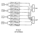
- each sound source S i two signals (left and right) which are then added to the left and right signals from the spatialization of all other sound sources, to finally give the signals L and R which will be broadcast in the left and right ears of the listener through two respective speakers (headphones of a binaural technique or remote speakers in transaural technique).
- N denotes the number of sound sources or incident audio streams to be spatialized
- the number of filters, or transfer functions, necessary for the binaural synthesis is 2xN for rendering in static binaural spatialization and 4xN for rendering in dynamic binaural spatialization (with transitions of transfer functions).
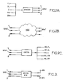
- left rear speaker and BR for a right rear speaker are encoded in compression by an ENCOD module capable of delivering two compressed L and R channels, as well as SPAT spatialization information.
- the compressed channels L and R, as well as the spatialization information SPAT are then conveyed through one or more telecommunication networks RES, on one or two channels according to the available bit rate ( Figure 2B ).
- a decoder reconstructs the original signal in the initial multichannel format by means of the SPAT spatialization information delivered by the coder and, in the example of Figures 2A and 2C , there are still five channels, after decoding, feeding five speakers (HP-FL, HP-FR, HP-C, HP-BL and HP-BR) for a 5.1 format playback.
- Audio encoders use time-frequency representations of signals to compress information. These representations are based on an analysis by filter banks or by time-frequency transformation of the MDCT type (for "Modified Discrete Cosine Transform"). In the case where a binaural spatialization must be performed after an audio decoding, the filtering operations are advantageously performed from the outset in the transformed domain.
- the subband filters in the transformed domain are calculated for each ear and for each of the five positions of the loudspeakers. This technique is often called “virtual speaker technology”.
- the binaural spatialization can then be advantageously performed by applying these binaural filters directly to the transformed domain at the heart of the decoder.
- DECOD BIN audio as shown on the figure 3 .
- this type of DECOD BIN decoder uses a monophonic or stereophonic representation (compressed L, R channels) of the multichannel audio scene, representation to which are associated SPAT spatialization parameters (which may consist, for example, of energy differences between channels and correlation indices between channels). These SPAT parameters are used at decoding to reproduce the original multichannel sound scene.
- the decoding can use representations decorrelated from these L, R signals (which are obtained, for example, by the application of filters, all-pass decorrelation or reverb filters). These signals are then adjusted in energy thanks to interchannel energy differences, then recombined to obtain the multichannel signal for restitution.
- the parametric encoder (ENCOD - Figure 2A ) from the multichannel format to two compressed channels (stereo or mono) according to the draft standard "MPEG Surround” provides cross-channel decorrelation information in the initial multichannel format and this decorrelation information can be taken over by the peer parametric decoder (DECOD - Figure 2C ) when rendering in the initial multichannel format.
- DECOD - Figure 2C peer parametric decoder
- phase compensation a function of the target energy of the channels, is to avoid a so-called "coloring" effect resulting from the addition of two filters shifted in time (comb filtering).
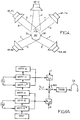
- a decoder receives the SPAT spatialization parameters accompanying the signals compressed on two L and R channels in the example shown, and it has been illustrated on this same Figure 5A , how the above filter h L, L applies to the compressed channel L to form a component of the L-BIN signal for binaural restitution. Nevertheless, as represented again on the Figure 5A , it is also necessary to take into account the compressed signal on the channel R which must, for its part, be filtered by a filter involving HRTF transfer functions (denoted H L, FR and H L, BR ) relating to the cross paths H and E of the figure 4 , always to the left ear.
- HRTF transfer functions decoder
- the filter corresponding to these crossed paths (denoted h L, R ) is computed according to the gains, target energies and phase shifts, taken from the SPAT spatialization parameters, using an expression equivalent to the relation (1) given previously. .
- This filter h L, R is finally applied to the compressed signal on the channel R. It is also necessary to take into account the "contribution" of the central loudspeaker in the construction of the signal intended for the binaural restitution L-BIN and, for this is done by applying a filter h L, C ( Figure 5A ) to a combination (for example by addition) of the compressed signals of the two channels L and R to take into account here the path J to the left ear OL of the figure 4 .
- FIG. 5B another example is shown, in which a decoder receives the compressed signal on a single channel M, accompanying the spatialization parameters SPAT.
- the M channel is duplicated in two L and R channels and the rest of the processing is strictly equivalent to the treatment shown in FIG. Figure 5A .
- the two signals L-BIN and R-BIN resulting from these filterings can then be applied to two loudspeakers intended respectively for the left ear and the right ear of the listener after a transition from the transformed domain to the time domain.
- the present invention improves the situation.
- the initial multichannel format can be of ambiophonic type (or "ambisonic" in English and aiming at the decomposition of the sound signal in a spherical harmonics base). Alternatively, it can be a type of 5.1 or 7.1, or 10.2. It will be understood that for the latter types of format using channels intended to respectively supply at least pairs of speakers front-left / left-back, on the one hand, and front-right / right-back, d On the other hand, the decorrelation information can be directed to the respective channels of the front / rear speakers preferably associated with the same ear (left or right).
- this decorrelation information at the rear of a 3D scene is represented in the binaural or transaural restitution, a better representation of the ambiences is obtained, for example crowd noise or reverberation at the back of a scene, or otherwise, contrary to the achievements of the prior art.
- This weighting advantageously makes it possible to favor the gross transfer function of this rear loudspeaker, or the decorrelated version of this raw transfer function, depending on whether the signal in the back channel of the initial multichannel format is correlated or not with at least one signal. from one of the front channels.
- the encoding in compression implements a parametric encoder delivering, in the compressed stream including the spatialization parameters, cross-channel decorrelation information of the multichannel format, from which the aforementioned weighting can be determined dynamically.
- the aforementioned combination of transfer functions takes advantage of the information already present concerning the correlation between channel signals in multichannel format, this information simply being provided by the coder parametric, with the aforementioned spatialization parameters.
- the parametric decoder according to the draft MPEG Surround standard delivers such cross-channel decorrelation information in multichannel 5.1 format.
- the compressed signal is first recovered on two L and R channels in the example represented, as well as the SPAT spatialization parameters provided by an encoder such as the ENCOD module of the Figure 2A previously described.
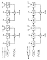
- transfer functions are determined to construct a combination of filters ("+" sign of the Figure 6A ), each filter being to be applied to a channel L (filter h L, L of the Figure 5A ), or R (filter h L, R of the Figure 5A ), or a combination of these channels (filter h L, C of the Figure 5A ) to construct a signal feeding one of two binaural L-BIN recovery channels.
- transfer functions are representative of the disturbances experienced by an acoustic wave on a path between a loudspeaker that would have been fed by a channel of the initial multichannel format and an ear of the listener. For example, if the audio content is initially in 5.1 format, as described above with reference to the figure 4 a total of ten HRTF transfer functions are determined, five HRTF functions for the right ear (on paths B, D, G, F and I of the figure 4 ) and five HRTF functions for the left ear (on the A, C, H, E and J paths).
- the HRTF functions of front and rear speakers, located on the same side of the listener are thus grouped to construct each filter of a filter combination specific to a playback channel on an ear of a listener.
- a grouping of HRTF functions to construct a filter is for example an addition, by means of multiplicative coefficients, an example of which will be described later.
- a decorrelated version of the HRTF functions of the loudspeakers located at the rear of the listener is also determined. figure 4 ) and this decorrelated version is integrated with each grouping to form a filter to be applied to a compressed channel.
- a similar treatment is planned to construct the signal intended to feed the other binaural R-BIN restitution channel of the Figure 6B .
- HRTF functions of the paths leading to the right ear OD of the listener AU ( figure 4 ).
- a first grouping includes the HRTF-G functions (for the right front speaker in a direct path), HRTF-F (for the right rear speaker in a direct path) and the decorrelated version HRTF-F * of the HRTF-F function to form the filter to be applied to the compressed channel R.
- a second grouping includes the function HRTF-B (for the front left speaker according to a cross path), the function HRTF-D (for the rear speaker left in a cross path) and the decorrelated version, denoted HRTF-D *, of the HRTF-D function, to form the filter to be applied to the compressed channel L.
- the filter combinations integrating the decorrelated versions of the HRTF functions of the rear loudspeakers are applied to the L and R compressed channels to deliver the L-BIN and R-BIN rendering channels, for spatial binaural rendering with 3D rendering.
- the received sound data is encoded in compression on two stereo channels L and R as illustrated in the example of the Figure 5A .
- they could be encoded in compression on a single monophonic channel M, as shown in FIG. Figure 5B , in which case the filter combinations are applied to the monophonic channel (duplicated) as shown in FIG. Figure 5B , to supply two signals supplying the two L-BIN, R-BIN reproduction channels respectively.
- the initial sound data is in the 5.1 multichannel format and is encoded in compression by a parametric encoder according to the aforementioned draft standard MPEG Surround. More particularly, during such encoding, it is possible to obtain, among the spatialization parameters provided, decorrelation information between the right rear channel and the right front channel (respective loudspeakers HP-BR and HP-FR of the figure 4 ), as well as homologous decorrelation information between the left rear channel and the left front channel (respective loudspeakers HP-FR and HP-BR of the figure 4 ).
- This decorrelation information in a 5.1 format, is intended to make the reproduction of the rear speakers as independent as possible from the reproduction of the front speakers, to enrich, in 5.1 format, the enveloping effect by noise of reverb or audience for concert recordings for example. It is recalled that this enrichment of the 3D envelopment has not been proposed in binaural restitution and an advantage of the invention is to take advantage of the availability of the decorrelation information among the SPAT spatialization parameters to build uncorrelated versions of the functions. HRTF that integrate advantageously with filter combinations for binaural restitution.
- these filter combinations can be calculated directly in the transformed domain, for example in the field of sub-bands, and the filters representing the decorrelated versions of the HRTF functions of the rear loudspeakers can be obtained for example by applying the initial HRTF functions a phase shift function of the sub-frequency band considered.
- the decorrelation filters can be so-called "natural" reverb filters (recorded in a particular acoustic environment such as a concert hall for example), or “synthetic” (created by summation of multiple reflections of decreasing amplitudes in the time).
- the application of a decorrelated filter can therefore return to apply to the signal broken down into frequency subbands a different phase difference in each of the subbands, combined with the addition of a global delay.
- a parametric decoder of the aforementioned type this amounts to multiplying each sub-frequency band by a complex exponential, of different phase in each sub-band. .
- These decorrelation filters can therefore correspond to syntheses of phase-shifting all-pass filters.
- a weighting is provided between the transfer function of a rear loudspeaker and its uncorrelated version in the same group forming a filter.
- the decorrelated version is preferred for crossed paths (right rear speaker for the left ear and left rear speaker for the right ear), so that, in general, the coefficient ⁇ 1 , may often be greater than the coefficient ⁇ 2 .
- the coefficients ⁇ ( ⁇ 1 or ⁇ 2 ) are given by variable weighting functions so as to dynamically favor the raw version of the HRTF function of the rear loudspeaker or its uncorrelated version depending on whether the back signal is correlated or no with the signal before. This gives a better representation of the ambiences (crowd noise, reverb, or other) in the 3D rendering.
- the weighting function ⁇ can be defined dynamically by means of the decorrelation information provided with the spatialization parameters.
- an equivalent expression can be applied to calculate the weighting coefficient ⁇ involved in the homologous filter h R, R specific to direct acoustic paths to the right ear.
- the "sqrt" function no longer applies for the crossed paths and for the calculation of the corresponding coefficient ⁇ 2 , in the example described.
- the target energies and the correlation indices are terms between 0 and 1 so that the coefficient ⁇ 2 is generally lower than the coefficient ⁇ 1 .
- the global filter combination for the L-BIN pathway, has many groupings of HRTF functions forming filters h L, L and h L, R obtained by the formulas given above, and in each grouping, the HRTF function is well involved. a front speaker, the HRTF function of a rear speaker and a decorrelated version of this Last function HRTF, which allows to represent a decorrelation between the front and back channels directly in the combination of filters, and thus directly in the binaural synthesis.
- the combination of filters can be directly applied in the transformed domain as a function of the target energies ( ⁇ FL , ⁇ BL , ⁇ FR , ⁇ BR ) associated with the channels of the multichannel format, these target energies being determined from the SPAT spatialization parameters.
- the transformation from the transformed domain to the time domain is then again planned for the actual reproduction in binaural context (TRANS modules).
- Figures 6A and 6B ).
- the present invention also aims at a computer program, intended to be stored in a memory of a decoding module, such that the MEM memory of the DECOD-BIN module of the figure 7 , for spatialized three-dimensional reproduction on two L-BIN and R-BIN rendering channels.
- the program then comprises instructions for executing the method according to the invention and, in particular, to construct the filter combinations integrating the uncorrelated versions as illustrated on the Figures 6A and 6B described above.
- one or the other of these figures can constitute a flowchart representing the algorithm underlying the program.
Landscapes
- Engineering & Computer Science (AREA)
- Physics & Mathematics (AREA)
- Acoustics & Sound (AREA)
- Signal Processing (AREA)
- Mathematical Physics (AREA)
- Human Computer Interaction (AREA)
- Health & Medical Sciences (AREA)
- Audiology, Speech & Language Pathology (AREA)
- Computational Linguistics (AREA)
- Multimedia (AREA)
- Algebra (AREA)
- General Physics & Mathematics (AREA)
- Mathematical Analysis (AREA)
- Mathematical Optimization (AREA)
- Pure & Applied Mathematics (AREA)
- Theoretical Computer Science (AREA)
- Stereophonic System (AREA)
- Golf Clubs (AREA)
Abstract
Description
L'invention concerne le traitement de données sonores, en vue d'une restitution spatialisée.The invention relates to the processing of sound data for spatialized reproduction.
La spatialisation sonore tridimensionnelle (dite « rendu 3D ») de signaux audio compressés intervient notamment lors de la décompression d'un signal audio 3D, par exemple codé en compression et représenté sur un certain nombre de canaux, vers un nombre de canaux différents (deux par exemple pour permettre la restitution des effets audio 3D sur un casque d'écoute).The three-dimensional sound spatialization (so-called "3D rendering") of compressed audio signals occurs especially during the decompression of a 3D audio signal, for example encoded in compression and represented on a number of channels, to a number of different channels (two for example to allow the rendering of 3D audio effects on a headset).
Le terme « binaural » vise la restitution sur un casque stéréophonique d'un signal sonore avec néanmoins des effets de spatialisation. L'invention ne se limite toutefois pas à la technique précitée et s'applique, notamment, à des techniques dérivées du « binaural », telles que les techniques de restitution dites techniques TRANSAURAL (marque déposée), c'est-à-dire sur des haut-parleurs distants. De telles techniques peuvent alors utiliser une « annulation de diaphonie » (ou « cross-talk cancellation » en anglais), laquelle consiste à annuler les chemins acoustiques croisés, de manière à ce qu'un son, ainsi traité puis émis par les haut-parleurs, puisse n'être perçu que par une seule des deux oreilles d'un auditeur. Par la suite, on désignera communément ces deux techniques de restitution, binaurale et transaurale, par les mêmes termes « restitution binaurale ».The term "binaural" aims at the reproduction on a stereophonic headphones of a sound signal with nevertheless effects of spatialization. The invention is however not limited to the aforementioned technique and applies, in particular, to techniques derived from the "binaural", such as the so-called technical rendering techniques TRANSAURAL (registered trademark), that is to say on remote speakers. Such techniques can then use a "crosstalk cancellation" (or "cross-talk cancellation" in English), which consists in canceling the crossed acoustic paths, so that a sound, thus processed and then emitted by the loudspeakers, speakers, can be perceived only by one of the two ears of a listener. Subsequently, these two binaural and transaural rendering techniques are commonly referred to as binaural restitution.
Ainsi, plus généralement, l'invention est relative à la transmission de signaux audio multicanaux et à leur conversion pour une restitution spatialisée (avec rendu 3D) sur deux voies. Le dispositif de restitution (simple casque à oreillettes par exemple) est le plus souvent imposé par l'équipement d'un utilisateur. La conversion peut viser par exemple le cas d'une restitution d'une scène sonore initialement au format multicanal 5.1 (ou 7.1, ou autre) par un simple casque d'écoute audio (en technique binaurale).Thus, more generally, the invention relates to the transmission of multichannel audio signals and their conversion for a spatialized rendering (with 3D rendering) on two channels. The rendering device (simple headset with earflaps for example) is most often imposed by the equipment of a user. The conversion can aim for example the case of a reproduction of a sound scene initially in 5.1 multichannel format (or 7.1, or other) by a simple audio headset (in binaural technique).
Bien entendu, l'invention concerne aussi la restitution, dans le cadre d'un jeu ou d'un enregistrement vidéo par exemple, d'un ou plusieurs échantillons sonores stockés dans des fichiers, en vue de leur spatialisation.Of course, the invention also relates to the restitution, in the frame of a game or a video recording, for example, of one or more sound samples stored in files, with a view to their spatialization.
Concernant l'art antérieur, référence est faite au document
Parmi les techniques connues dans le domaine de la spatialisation sonore binaurale, différentes approches ont été proposées.Among the known techniques in the field of binaural sound spatialization, different approaches have been proposed.
En particulier, la synthèse binaurale bicanale consiste, en référence à la
- associer à chaque source sonore Si (ou chaque canal du signal multicanal) une position dans l'espace,
- filtrer ces sources dans le domaine fréquentiel par les fonctions de transfert acoustiques gauche HRTF-I et droite HRTF-r correspondant à la direction (ou à la position) choisie, et définies par leurs coordonnées polaires (θ1, ϕ1 ).
- associating with each sound source S i (or each channel of the multichannel signal) a position in the space,
- filtering these sources in the frequency domain by the left HRTF-I and right HRTF-r acoustic transfer functions corresponding to the direction (or position) chosen, and defined by their polar coordinates (θ 1 , φ 1 ).
Ces fonctions de transfert, communément dites fonctions « HRTF » (pour « Head Related Transfer Functions » en anglais), représentent les fonctions de transfert acoustique entre les positions de l'espace et le conduit auditif de chaque oreille de l'auditeur. On désigne par « HRIR » (pour « Head Related Impulse Response » en anglais) leur forme temporelle ou réponse impulsionnelle. Ces fonctions HRIR peuvent inclure en outre un effet de salle.These transfer functions, commonly known as "HRTF" functions (for "Head Related Transfer Functions"), represent the acoustic transfer functions between the positions of the space and the auditory canal of each ear of the listener. The term "HRIR" (for "Head Related Impulse Response") denotes their temporal form or impulse response. These HRIR functions may further include a room effect.
On obtient, pour chaque source sonore Si deux signaux (gauche et droit) qui sont alors additionnés aux signaux de gauche et de droite issus de la spatialisation de toutes les autres sources sonores, pour donner finalement les signaux L et R qui seront diffusés dans les oreilles gauche et droite de l'auditeur à travers deux haut-parleurs respectifs (oreillettes d'un casque en technique binaurale ou haut-parleurs distants en technique transaurale).We obtain for each sound source S i two signals (left and right) which are then added to the left and right signals from the spatialization of all other sound sources, to finally give the signals L and R which will be broadcast in the left and right ears of the listener through two respective speakers (headphones of a binaural technique or remote speakers in transaural technique).
Si N désigne le nombre de sources sonores ou de flux audio incidents à spatialiser, le nombre de filtres, ou fonctions de transfert, nécessaire à la synthèse binaurale est 2xN pour un rendu en spatialisation binaurale statique et 4xN pour un rendu en spatialisation binaurale dynamique (avec transitions des fonctions de transfert).If N denotes the number of sound sources or incident audio streams to be spatialized, the number of filters, or transfer functions, necessary for the binaural synthesis is 2xN for rendering in static binaural spatialization and 4xN for rendering in dynamic binaural spatialization ( with transitions of transfer functions).
Le traitement décrit ci-avant en référence à la
Néanmoins, l'invention part d'un autre type d'art antérieur.Nevertheless, the invention starts from another type of prior art.
Il existe des techniques de compression, souvent dans un domaine transformé, de signaux dans un format multicanal pour pouvoir véhiculer ces signaux, notamment à travers des réseaux de télécommunication, sur un nombre restreint de canaux, par exemple un ou deux canaux seulement. Ainsi, pour l'émission d'un signal dans un format multicanal comportant plus de deux canaux (par exemple 5.1, 7.1 ou autre), un codeur compresse le signal multicanal sur uniquement un ou deux canaux (typiquement selon le débit offert sur le réseau de télécommunication) et délivre en outre des informations de spatialisation. Cette réalisation est illustrée sur la
En référence à la
De nombreux types de codeurs/décodeurs paramétriques, notamment normalisés, offrent de telles possibilités.Many types of parametric encoders / decoders, including standardized ones, offer such possibilities.
Les codeurs audio (AAC, MP3) utilisent des représentations temps-fréquence des signaux pour compresser les informations. Ces représentations sont basées sur une analyse par bancs de filtres ou par transformation temps-fréquence de type MDCT (pour « Modified Discrete Cosine Transform »). Dans le cas où une spatialisation binaurale doit être effectuée après un décodage audio, les opérations de filtrage sont avantageusement réalisées d'emblée dans le domaine transformé.Audio encoders (AAC, MP3) use time-frequency representations of signals to compress information. These representations are based on an analysis by filter banks or by time-frequency transformation of the MDCT type (for "Modified Discrete Cosine Transform"). In the case where a binaural spatialization must be performed after an audio decoding, the filtering operations are advantageously performed from the outset in the transformed domain.
Des travaux récents sur le filtrage dans le domaine transformé de sous-bandes ont permis de formaliser l'architecture de filtrage pour un banc de filtres couramment utilisé dans les codeurs audio. On pourra se référer utilement au document :
- "
A Generic Framework for Filtering in Subband Domain", A.Benjelloun Touimi, Proceeding IEEE - 9th Workshop on Digital Signal Processing, Hunt, Texas, USA, Octobre 2000
- "
A Generic Framework for Filtering in Subband Domain ", A.Benjelloun Touimi, Proceeding IEEE - 9th Workshop on Digital Signal Processing, Hunt, Texas, USA, October 2000
Une technique plus récente de filtrage dans le domaine transformé des QMF complexes (pour « Quadrature Mirror Filters ») a été proposée dans la norme « MPEG Surround ». Cette technique vise la conversion de la réponse impulsionnelle (finie) du filtre temporel noté h(v) en un ensemble de M filtres complexes notés hm(l), où M est le nombre de sous-bandes de fréquences. La conversion est réalisée par analyse du filtre temporel h(v) par un banc de filtres complexes similaire au banc de filtres QMF utilisé pour l'analyse du signal. Dans un exemple de réalisation, le filtre prototype q(v) utilisé pour générer le banc de filtre de conversion peut être de longueur 192. On définit une extension avec des zéros du filtre temporel par la formule suivante: 
- Nh est la longueur du filtre dans le domaine temporel,
- Lq /Kh +2, avec kh =[N h/ 64], la longueur des filtres en sous-bandes (pour 64 sous-bandes).
- N h is the length of the filter in the time domain,
- L q / K h + 2, with k h = [ N h / 64], the length of the filters in sub-bands (for 64 subbands).
La conversion est donc donnée par la formule suivante :
- m = 0,1,...,63 , correspondant à l'indice de la sous-bande
- l =0,1,..., Kh +1 , correspondant à l'indice temporel dans le domaine décimé des sous-bandes.
- m = 0.1, ..., 63, corresponding to the index of the sub-band
- l = 0.1 , ..., K h +1 , corresponding to the time index in the decimated domain of the subbands.
En termes plus génériques, on comprendra qu'un tel traitement, directement dans le domaine transformé, permet de passer d'une représentation du signal compressé sur deux canaux L, R vers une représentation du signal sur deux voies de restitution L-BIN, R-BIN (
Ainsi, en référence maintenant à la
- une pour le chemin A entre le haut-parleur avant gauche HP-FL et l'oreille gauche OL de l'auditeur AU,
- une pour le chemin B entre le haut-parleur avant gauche HP-FL et l'oreille droite OR de l'auditeur AU,
- une pour le chemin C entre le haut-parleur arrière gauche HP-BL et l'oreille gauche OL de l'auditeur AU,
- une pour le chemin D entre le haut-parleur arrière gauche HP-BL et l'oreille droite OR de l'auditeur AU,
- une pour le chemin G entre le haut-parleur avant droit HP-FR et l'oreille droite OR de l'auditeur AU,
- une pour le chemin H entre le haut-parleur avant droit HP-FR et l'oreille gauche OL de l'auditeur AU,
- une pour le chemin F entre le haut-parleur arrière droit HP-BR et l'oreille droite OR de l'auditeur AU,
- une pour le chemin E entre le haut-parleur arrière droit HP-BR et l'oreille gauche OL de l'auditeur AU,
- une pour le chemin J entre le haut-parleur du centre HP-C et l'oreille gauche OL de l'auditeur AU, et
- une pour le chemin I entre le haut-parleur du centre HP-C et l'oreille droite OR.
- one for path A between the left front speaker HP-FL and the left ear OL of the AU listener,
- one for path B between the left front speaker HP-FL and the right ear OR of the AU listener,
- one for path C between the left rear loudspeaker HP-BL and the left ear OL of the listener AU,
- one for the path D between the left rear loudspeaker HP-BL and the right ear OR of the listener AU,
- one for the G path between the right front speaker HP-FR and the right ear OR of the AU listener,
- one for the H path between the HP-FR right front speaker and the left ear OL of the AU listener,
- one for path F between the right rear speaker HP-BR and the right ear OR of the AU listener,
- one for the path E between the right rear speaker HP-BR and the left ear OL of the listener AU,
- one for the path J between the loudspeaker of the center HP-C and the left ear OL of the listener AU, and
- one for path I between the center speaker HP-C and the right ear OR.
Ainsi, les filtres en sous-bandes dans le domaine transformé sont calculés pour chaque oreille et pour chacune des cinq positions des haut-parleurs. Cette technique est souvent appelée « technique des haut-parleurs virtuels ».Thus, the subband filters in the transformed domain are calculated for each ear and for each of the five positions of the loudspeakers. This technique is often called "virtual speaker technology".
A l'aide de la représentation en sous-bandes des filtres binauraux déterminés comme décrit ci-avant à partir des fonctions de transfert HRTF, la spatialisation binaurale peut alors être avantageusement réalisée en appliquant ces filtres binauraux directement dans le domaine transformé au coeur du décodeur audio DECOD BIN comme représenté sur la
Ainsi, ce type de décodeur DECOD BIN utilise une représentation monophonique ou stéréophonique (voies compressées L, R) de la scène audio multicanal, représentation à laquelle sont associés des paramètres de spatialisation SPAT (qui peuvent consister par exemple en des différences d'énergies entre canaux et indices de corrélation entre canaux). Ces paramètres SPAT sont utilisés au décodage pour reproduire au mieux la scène sonore multicanal originale.Thus, this type of DECOD BIN decoder uses a monophonic or stereophonic representation (compressed L, R channels) of the multichannel audio scene, representation to which are associated SPAT spatialization parameters (which may consist, for example, of energy differences between channels and correlation indices between channels). These SPAT parameters are used at decoding to reproduce the original multichannel sound scene.
En outre, lorsque le signal original est encodé par un codeur paramétrique (par exemple au sens de travaux récents dans la norme « MPEG Surround »), en plus du signal monophonique ou stéréophonique transmis et des informations de spatialisation, le décodage peut utiliser des représentations décorrélées de ces signaux L, R (qui sont obtenues, par exemple, par l'application de filtres, de décorrélation passe-tout ou de filtres de réverbération). Ces signaux sont ensuite ajustés en énergie grâce aux différences d'énergie intercanal, puis recombinés pour obtenir le signal multicanal en vue de la restitution.In addition, when the original signal is encoded by a parametric encoder (for example in the sense of recent work in the "MPEG Surround" standard), in addition to the monophonic or stereophonic signal transmitted and spatialization information, the decoding can use representations decorrelated from these L, R signals (which are obtained, for example, by the application of filters, all-pass decorrelation or reverb filters). These signals are then adjusted in energy thanks to interchannel energy differences, then recombined to obtain the multichannel signal for restitution.
En particulier, l'encodeur paramétrique (ENCOD -
Une description de travaux préparatoires à cette norme est donnée à l'adresse URL :
- « http://www.chiariglione.org/mpeg/technologies/mpd-mps/index.htm »
- "
MPEG Spatial Audio Coding / MPEG Surround: Overview and Current Status", J.Breebaart et al., dans 119th Conv. Aud. Eng. Soc (AES), New York, NY, USA, Octobre 2005
- "Http://www.chiariglione.org/mpeg/technologies/mpd-mps/index.htm"
- "
MPEG Spatial Audio Coding / MPEG Surround: Overview and Current Status ", J.Breebaart et al., In 119th Conv. Aud. Eng. Soc (AES), New York, NY, USA, October 2005
Dans le cas d'un décodeur audio paramétrique pour une restitution binaurale (DECOD BIN - 
Dans cette expression :
- hL,L est le filtre correspondant aux contributions des canaux avant et arrière gauche,
- gL,L est le gain associé à l'ensemble des canaux gauches,
- σ2 FL et σ2 BL sont les énergies utiles des canaux respectivement avant et arrière gauches,
- hL,FL et hL,BL sont les fonctions de transfert dans le domaine des sous-bandes entre l'oreille gauche et les haut-parleurs respectivement avant et arrière gauche (chemins A et C de la
figure 4 ), - ΦL FL,BL est le déphasage correspondant au retard entre les filtres temporels avant et arrière gauche hL,FL et hL,BL.
- h L , L is the filter corresponding to the contributions of the left front and rear channels,
- g L , L is the gain associated with all the left channels,
- σ 2 FL and σ 2 BL are the useful energies of the respectively front and left channels,
- h L, FL and h L, BL are the transfer functions in the field of the sub-bands between the left ear and the speakers respectively front and rear left (paths A and C of the
figure 4 ) - Φ L FL, BL is the phase shift corresponding to the delay between the forward and backward time filters h L, FL and h L, BL .
Le but de cette compensation de phase, fonction de l'énergie cible des canaux, est d'éviter un effet dit « de coloration » issu de l'addition de deux filtres décalés dans le temps (filtrage en peigne).The purpose of this phase compensation, a function of the target energy of the channels, is to avoid a so-called "coloring" effect resulting from the addition of two filters shifted in time (comb filtering).
En référence à la
En référence encore à la
- le signal compressé sur le canal R filtré par le filtre hR,R représentant les fonctions HRTF des haut-parleurs de droite (chemins directs G et F de la
figure 4 ) ; - le signal compressé sur le canal L filtré par le filtre hR,L représentant les fonctions HRTF des haut-parleurs de gauche (chemins croisés B et D de la
figure 4 ) ; et - une combinaison des signaux compressés L et R filtrée par le filtre hR,C représentant les fonctions HRTF du haut-parleur de centre (chemin direct I de la
figure 4 ).
- the signal compressed on the R channel filtered by the filter h R, R representing the HRTF functions of the right speakers (direct paths G and F of the
figure 4 ); - the compressed signal on the channel L filtered by the filter h R, L representing the HRTF functions of the left speakers (crossed paths B and D of the
figure 4 ); and - a combination of the compressed signals L and R filtered by the filter h R, C representing the HRTF functions of the center loudspeaker (direct path I of the
figure 4 ).
Sur la
Les deux signaux L-BIN et R-BIN résultant de ces filtrages peuvent être appliqués ensuite à deux haut-parleurs destinés respectivement à l'oreille gauche et à l'oreille droite de l'auditeur après un passage du domaine transformé au domaine temporel.The two signals L-BIN and R-BIN resulting from these filterings can then be applied to two loudspeakers intended respectively for the left ear and the right ear of the listener after a transition from the transformed domain to the time domain.
Toutefois, un problème lié à cette combinaison de filtres pour une restitution binaurale est qu'elle ne prend pas en compte une éventuelle décorrélation entre les canaux avant et arrière. Cette information, pourtant utilisée dans le décodage d'une scène 5.1 d'un encodeur selon le projet précité de la norme MPEG Surround, n'est pas exploitée dans la technique de décodage binaural. Ainsi, lorsque la scène sonore comporte des effets de décorrélation entre les canaux avant et arrière (par exemple pour des signaux réverbérés), cette information n'est pas utilisée dans la combinaison des filtres HRTF, ce qui entraîne une dégradation de la qualité de spatialisation et notamment de l'effet d'enveloppement de la scène audio 3D. Ainsi, la restitution au format binaural n'est pas optimale.However, a problem with this combination of filters for binaural playback is that it does not take into account any decorrelation between the front and rear channels. This information, however used in the decoding of a 5.1 scene of an encoder according to the aforementioned project of the MPEG Surround standard, is not exploited in the binaural decoding technique. Thus, when the sound scene includes decorrelating effects between the front and rear channels (for example for reverberated signals), this information is not used in the combination of the HRTF filters, which leads to a degradation of the spatialization quality. and in particular the enveloping effect of the 3D audio scene. Thus, the binaural format is not optimal.
La présente invention vient améliorer la situation.The present invention improves the situation.
Elle vise tout d'abord un procédé de traitement de données sonores pour une restitution spatialisée en trois dimensions sur deux voies de restitution pour les oreilles respectives d'un auditeur,
les données sonores étant initialement représentées dans un format multicanal puis encodées en compression sur un nombre réduit de canaux (par exemple un ou deux canaux),
ledit format multicanal initial consistant à prévoir plus de deux canaux susceptibles d'alimenter des haut-parleurs respectifs,
le procédé comportant les étapes :
- obtenir, avec les données compressées sur ledit nombre réduit de canaux, des paramètres de spatialisation,
- pour chaque voie de restitution associée à une oreille de l'auditeur, former, à partir desdits paramètres de spatialisation, une combinaison de filtres représentatifs chacun de fonctions de transfert entre cette oreille de l'auditeur et des haut-parleurs susceptibles d'être alimentés par des canaux respectifs du format multicanal initial, et
- appliquer aux données compressées la combinaison de filtres associée à chaque voie de restitution.
the sound data being initially represented in a multichannel format and then encoded in compression on a reduced number of channels (for example one or two channels),
said initial multichannel format consisting of providing more than two channels capable of supplying respective loudspeakers,
the process comprising the steps:
- obtain, with the compressed data on said reduced number of channels, spatialization parameters,
- for each playback channel associated with an ear of the listener, forming, from said spatialization parameters, a combination of filters representative each of transfer functions between this listener's ear and speakers capable of being powered by respective channels of the initial multichannel format, and
- apply to the compressed data the filter combination associated with each rendition channel.
Le procédé au sens de l'invention comporte en outre les étapes :
- pour chaque voie de restitution associée à une oreille de l'auditeur, déterminer à partir desdits paramètres de spatialisation au moins une fonction de transfert d'un haut-parleur situé à l'arrière de l'oreille de l'auditeur et représentative d'une décorrélation entre les canaux du format multicanal respectivement associés au haut-parleur arrière et à au moins un haut-parleur situé devant l'oreille de l'auditeur, et
- pour chaque voie de restitution, intégrer ladite fonction de transfert représentative d'une décorrélation dans ladite combinaison de filtres associée à cette voie de restitution.
- for each playback channel associated with an ear of the listener, determining from said spatialization parameters at least one transfer function of a loudspeaker located at the back of the listener's ear and representative of a decorrelation between the channels of the multichannel format respectively associated with the rear loudspeaker and at least one speaker located in front of the listener's ear, and
- for each rendering channel, integrating said transfer function representative of a decorrelation in said combination of filters associated with this rendering path.
La restitution spatialisée sur deux voies, au sens de l'invention, peut être aussi bien au format binaural ou transaural. Le format multicanal, initial peut être de type ambiophonique (ou « ambisonic » en anglais et visant la décomposition du signal sonore dans une base d'harmoniques sphérique). En variante, il peut s'agir d'un format de type 5.1 ou 7.1, ou encore 10.2. On comprendra alors que pour ces derniers types de format mettant en oeuvre des canaux destinés à alimenter respectivement au moins des couples de haut-parleurs avant-gauche/arrière-gauche, d'une part, et avant-droit/arrière-droit, d'autre part, l'information de décorrélation peut viser les canaux respectifs des haut-parleurs avant/arrière préférentiellement associés à une même oreille (gauche ou droite).Spatial restitution on two paths, within the meaning of the invention, can be in binaural or transaural format as well. The initial multichannel format can be of ambiophonic type (or "ambisonic" in English and aiming at the decomposition of the sound signal in a spherical harmonics base). Alternatively, it can be a type of 5.1 or 7.1, or 10.2. It will be understood that for the latter types of format using channels intended to respectively supply at least pairs of speakers front-left / left-back, on the one hand, and front-right / right-back, d On the other hand, the decorrelation information can be directed to the respective channels of the front / rear speakers preferably associated with the same ear (left or right).
Selon un avantage que procure l'invention, du fait que cette information de décorrélation à l'arrière d'une scène 3D soit représentée dans la restitution binaurale ou transaurale, on obtient une meilleure représentation des ambiances, par exemple des bruits de foule ou une réverbération à l'arrière d'une scène, ou autre, contrairement aux réalisations de l'art antérieur.According to one advantage provided by the invention, since this decorrelation information at the rear of a 3D scene is represented in the binaural or transaural restitution, a better representation of the ambiances is obtained, for example crowd noise or reverberation at the back of a scene, or otherwise, contrary to the achievements of the prior art.
Dans un mode de réalisation particulier, la combinaison de filtres comporte une pondération, selon un coefficient choisi, entre :
- une fonction de transfert brute du haut-parleur situé à l'arrière, et
- une version de la fonction de transfert de ce haut-parleur, représentative de la décorrélation.
- a function of raw transfer of the loudspeaker located at the back, and
- a version of the transfer function of this speaker, representative of the decorrelation.
Cette pondération permet avantageusement de favoriser la fonction de transfert brute de ce haut-parleur arrière, ou la version décorrélée de cette fonction de transfert brute, selon que le signal dans le canal arrière du format multicanal initial est corrélé ou non avec au moins un signal de l'un des canaux avant.This weighting advantageously makes it possible to favor the gross transfer function of this rear loudspeaker, or the decorrelated version of this raw transfer function, depending on whether the signal in the back channel of the initial multichannel format is correlated or not with at least one signal. from one of the front channels.
Par ailleurs, dans une réalisation particulière, la combinaison de filtres associée à une voie de restitution comporte au moins un regroupement formant filtre à partir de :
- la fonction de transfert d'un haut-parleur avant,
- la fonction de transfert d'un haut-parleur arrière, et
- la fonction de transfert représentative d'une décorrélation entre canaux,
- the transfer function of a front speaker,
- the transfer function of a rear speaker, and
- the representative transfer function of a decorrelation between channels,
Avantageusement, l'encodage en compression met en oeuvre un codeur paramétrique délivrant, dans le flux compressé incluant les paramètres de spatialisation, une information de décorrélation entre canaux du format multicanal, à partir de laquelle peut être déterminée, de façon dynamique, la pondération précitée.Advantageously, the encoding in compression implements a parametric encoder delivering, in the compressed stream including the spatialization parameters, cross-channel decorrelation information of the multichannel format, from which the aforementioned weighting can be determined dynamically. .
Ainsi, dans cette réalisation, pour un transcodage entre un format multicanal vers un format binaural, la combinaison précitée de fonctions de transfert tire parti des informations déjà présentes concernant la corrélation entre signaux de canaux au format multicanal, ces informations étant simplement fournies par le codeur paramétrique, avec les paramètres de spatialisation précités.Thus, in this embodiment, for a transcoding between a multichannel format and a binaural format, the aforementioned combination of transfer functions takes advantage of the information already present concerning the correlation between channel signals in multichannel format, this information simply being provided by the coder parametric, with the aforementioned spatialization parameters.
A titre d'exemple, on rappelle que le décodeur paramétrique selon le projet de norme MPEG Surround délivre une telle information de décorrélation entre canaux au format multicanal 5.1.By way of example, it is recalled that the parametric decoder according to the draft MPEG Surround standard delivers such cross-channel decorrelation information in multichannel 5.1 format.
D'autres avantages et caractéristiques de l'invention apparaîtront à la lecture de la description détaillée donnée ci-après à titre d'exemple, et à l'observation des dessins annexés, dans lesquels, outre les
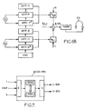
- les
figures 6A et6B illustrent à titre d'exemple un traitement par filtrage de données compressées (sur deux canaux dans l'exemple représenté), le filtrage étant déterminé par la mise en oeuvre du procédé au sens de l'invention pour délivrer des signaux L-BIN et R-BIN destinés à alimenter respectivement les voies gauche et droite d'un dispositif de restitution binaurale tel qu'un casque à deux oreillettes, en tenant compte d'une décorrélation avant/arrière, et - la
figure 7 illustre schématiquement la structure d'un module mettant en oeuvre le procédé au sens de l'invention.
- the
Figures 6A and6B illustrate by way of example a filtering treatment of compressed data (on two channels in the example shown), the filtering being determined by the implementation of the method according to the invention for delivering L-BIN and R signals -BIN for respectively feeding the left and right channels of a binaural rendering device such as a headset with two earpieces, taking into account a forward / backward decorrelation, and - the
figure 7 schematically illustrates the structure of a module implementing the method in the sense of the invention.
En référence à la
Ainsi, en termes généraux, les fonctions HRTF de haut-parleurs avant et arrière, situés sur un même côté de l'auditeur sont donc regroupées pour construire chaque filtre d'une combinaison de filtres propre à une voie de restitution sur une oreille d'un auditeur. Un regroupement de fonctions HRTF pour construire un filtre est par exemple une addition, moyennant des coefficients multiplicatifs dont un exemple sera décrit plus loin.Thus, in general terms, the HRTF functions of front and rear speakers, located on the same side of the listener are thus grouped to construct each filter of a filter combination specific to a playback channel on an ear of a listener. A grouping of HRTF functions to construct a filter is for example an addition, by means of multiplicative coefficients, an example of which will be described later.
Au sens de l'invention, à partir des paramètres de spatialisation SPAT récupérés, on détermine en outre une version décorrélée des fonctions HRTF des haut-parleurs situés à l'arrière de l'auditeur (chemins C, D, E et F de la
A titre d'exemple purement illustratif, les données sonores initiales peuvent être au format multicanal 5.1 et, en référence à la
- la fonction HRTF-A (pour le haut-parleur avant gauche selon un chemin direct vers l'oreille gauche OL de la
figure 4 ), - la fonction HRTF-C (pour le haut-parleur arrière gauche selon un chemin direct vers l'oreille gauche),
- et la version décorrélée de cette fonction HRTF-C, notée HRTF-C*, pour former le filtre à appliquer au canal compressé L.
- la fonction HRTF-H (pour le haut-parleur avant droit selon un chemin croisé vers l'oreille gauche),
- la fonction HRTF-E (pour le haut-parleur arrière droit selon un chemin croisé),
- et la version décorrélée de cette fonction HRTF-E, notée HRTF-E*, pour former le filtre à appliquer au canal compressé R.
- the function HRTF-A (for the front left speaker in a direct path to the left ear OL of the
figure 4 ) - the HRTF-C function (for the left rear speaker in a direct path to the left ear),
- and the decorrelated version of this HRTF-C function, denoted HRTF-C *, to form the filter to be applied to the compressed channel L.
- the HRTF-H function (for the right front speaker in a cross path to the left ear),
- the HRTF-E function (for the right rear speaker in a cross path),
- and the decorrelated version of this HRTF-E function, denoted HRTF-E *, to form the filter to be applied to the compressed channel R.
Un traitement similaire est prévu pour construire le signal destiné à alimenter l'autre voie de restitution binaurale R-BIN de la
Finalement, les combinaisons de filtres intégrant les versions décorrélées des fonctions HRTF des haut-parleurs arrière sont appliquées aux canaux compressés L et R pour délivrer les voies de restitution L-BIN et R-BIN, pour une restitution binaurale spatialisée avec rendu 3D.Finally, the filter combinations integrating the decorrelated versions of the HRTF functions of the rear loudspeakers are applied to the L and R compressed channels to deliver the L-BIN and R-BIN rendering channels, for spatial binaural rendering with 3D rendering.
Dans l'exemple représenté sur les
Dans une réalisation avantageuse, les données sonores initiales sont au format multicanal 5.1 et sont encodées en compression par un codeur paramétrique selon le projet de norme précité MPEG Surround. Plus particulièrement, lors d'un tel encodage, il est possible d'obtenir, parmi les paramètres de spatialisation fournis, une information de décorrélation entre le canal arrière droit et le canal avant droit (haut-parleurs respectifs HP-BR et HP-FR de la
Ces informations de décorrélation, dans un format 5.1, visent à rendre la restitution des haut-parleurs arrière la plus indépendante possible de la restitution des haut-parleurs avant, pour enrichir, au format 5.1, l'effet d'enveloppement par des bruits de réverbération ou de public pour des enregistrements de concerts par exemple. On rappelle que cet enrichissement de l'enveloppement 3D n'a pas été proposé en restitution binaurale et un avantage de l'invention est de tirer profit de la disponibilité des informations de décorrélation parmi les paramètres de spatialisation SPAT pour construire des versions décorrélées des fonctions HRTF qui s'intègrent avantageusement aux combinaisons de filtres pour une restitution binaurale.This decorrelation information, in a 5.1 format, is intended to make the reproduction of the rear speakers as independent as possible from the reproduction of the front speakers, to enrich, in 5.1 format, the enveloping effect by noise of reverb or audience for concert recordings for example. It is recalled that this enrichment of the 3D envelopment has not been proposed in binaural restitution and an advantage of the invention is to take advantage of the availability of the decorrelation information among the SPAT spatialization parameters to build uncorrelated versions of the functions. HRTF that integrate advantageously with filter combinations for binaural restitution.
Selon un autre avantage, ces combinaisons de filtres peuvent être calculées directement dans le domaine transformé, par exemple dans le domaine des sous-bandes, et les filtres représentant les versions décorrélées des fonctions HRTF des haut-parleurs arrière peuvent être obtenues par exemple en appliquant aux fonctions HRTF initiales un déphasage fonction de la sous-bande de fréquences considérée.According to another advantage, these filter combinations can be calculated directly in the transformed domain, for example in the field of sub-bands, and the filters representing the decorrelated versions of the HRTF functions of the rear loudspeakers can be obtained for example by applying the initial HRTF functions a phase shift function of the sub-frequency band considered.
Plus généralement, les filtres de décorrélation peuvent être des filtres de réverbération dite « naturelle » (enregistrée dans un environnement acoustique particulier comme une salle de concert par exemple), ou « synthétique » (créée par sommation de réflexions multiples d'amplitudes décroissantes dans le temps). L'application d'un filtre décorrélé peut donc revenir à appliquer au signal décomposé en sous-bandes de fréquences un déphasage différent dans chacune des sous-bandes, combiné avec l'ajout d'un délai global. Dans le cas d'un décodeur paramétrique du type précité (formule (1) donnée précédemment en description de l'art antérieur), cela revient à multiplier chaque sous-bande de fréquences par une exponentielle complexe, de phase différente dans chaque sous-bande. Ces filtres de décorrélation peuvent donc correspondre à des synthèses de filtres passe-tout déphaseur.More generally, the decorrelation filters can be so-called "natural" reverb filters (recorded in a particular acoustic environment such as a concert hall for example), or "synthetic" (created by summation of multiple reflections of decreasing amplitudes in the time). The application of a decorrelated filter can therefore return to apply to the signal broken down into frequency subbands a different phase difference in each of the subbands, combined with the addition of a global delay. In the case of a parametric decoder of the aforementioned type (formula (1) given previously in the description of the prior art), this amounts to multiplying each sub-frequency band by a complex exponential, of different phase in each sub-band. . These decorrelation filters can therefore correspond to syntheses of phase-shifting all-pass filters.
On prévoit avantageusement une pondération entre la fonction de transfert d'un haut-parleur arrière et sa version décorrélée dans un même regroupement formant un filtre. Ainsi, en reprenant la formule (1) donnée précédemment pour le calcul d'un filtre par exemple hL,L pour l'oreille gauche, on introduit des coefficients de pondération α et (1-α) et la version décorrélée d'une fonction de transfert comme suit : ![]()
Par exemple pour le filtre h L,R propre aux chemins croisés vers l'oreille gauche, on a : ![]()
![]()
For example, for the filter H L, R specific to paths crossed to the left ear, we have: ![]()
Plus spécifiquement, on prévoit une pondération par des coefficients différents α1, (1-α1) et α2, (1-α2) selon le fait que le haut-parleur arrière est du même côté que l'oreille considérée (α=α1 donnant les filtres h L,L et hR,R) ou non (α=α2 donnant les filtres hL,R et h R,L ). Préférentiellement, on privilégie la version décorrélée pour des chemins croisés (haut-parleur arrière droit pour l'oreille gauche et haut-parleur arrière gauche pour l'oreille droite), de sorte qu'en général, le coefficient α1, pourra être souvent supérieur au coefficient α2.More specifically, weighting is provided by different coefficients α 1 , (1-α 1 ) and α 2 , (1-α 2 ) depending on whether the rear loudspeaker is on the same side as the considered ear (α = α 1 giving the filters h L, L and h R , R ) or not (α = α 2 giving the filters h L , R and h R, L ). Preferably, the decorrelated version is preferred for crossed paths (right rear speaker for the left ear and left rear speaker for the right ear), so that, in general, the coefficient α 1 , may often be greater than the coefficient α 2 .
En pratique, les coefficients α (α1 ou α2) sont donnés par des fonctions de pondération variables de manière à favoriser dynamiquement la version brute de la fonction HRTF du haut-parleur arrière ou sa version décorrélée selon que le signal arrière est corrélé ou non avec le signal avant. On obtient ainsi une meilleure représentation des ambiances (bruits de foule, réverbération, ou autre) dans le rendu 3D.
La fonction de pondération α peut être définie dynamiquement grâce à l'information de décorrélation fournie avec les paramètres de spatialisation, à titre d'exemple non limitatif, de la façon suivante : ![]()
![]()
![]()
![]()
le terme σBR représentant l'énergie cible du canal arrière droit et le terme ICCR représentant l'indice de corrélation entre le canal avant droit et le canal arrière droit.
On relèvera que la fonction « sqrt » ne s'applique plus pour les chemins croisés et pour le calcul du coefficient correspondant α2, dans l'exemple décrit. En effet, les énergies cibles et les indices de corrélation sont des termes compris entre 0 et 1 de sorte que le coefficient α2 est généralement inférieur au coefficient α1.In practice, the coefficients α (α 1 or α 2 ) are given by variable weighting functions so as to dynamically favor the raw version of the HRTF function of the rear loudspeaker or its uncorrelated version depending on whether the back signal is correlated or no with the signal before. This gives a better representation of the ambiances (crowd noise, reverb, or other) in the 3D rendering.
The weighting function α can be defined dynamically by means of the decorrelation information provided with the spatialization parameters. as a non-limitative example, as follows: ![]()
![]()
![]()
![]()
the term σ BR representing the target energy of the right rear channel and the term ICC R representing the correlation index between the right front channel and the right rear channel.
It will be noted that the "sqrt" function no longer applies for the crossed paths and for the calculation of the corresponding coefficient α 2 , in the example described. Indeed, the target energies and the correlation indices are terms between 0 and 1 so that the coefficient α 2 is generally lower than the coefficient α 1 .
La combinaison de filtres globale, pour la voie L-BIN, comporte bien des regroupements de fonctions HRTF formant des filtres h L,L et h L,R obtenus par les formules données précédemment, et, dans chaque regroupement, interviennent bien la fonction HRTF d'un haut-parleur avant, la fonction HRTF d'un haut-parleur arrière et une version décorrélée de cette dernière fonction HRTF, ce qui permet de représenter une décorrélation entre les canaux avant et arrière directement dans la combinaison de filtres, et donc directement dans la synthèse binaurale.The global filter combination, for the L-BIN pathway, has many groupings of HRTF functions forming filters h L, L and h L, R obtained by the formulas given above, and in each grouping, the HRTF function is well involved. a front speaker, the HRTF function of a rear speaker and a decorrelated version of this Last function HRTF, which allows to represent a decorrelation between the front and back channels directly in the combination of filters, and thus directly in the binaural synthesis.
On rappelle que, les données sonores L, R (ou M) étant encodées en compression dans un domaine transformé, la combinaison de filtres peut être appliquée directement dans le domaine transformé en fonction des énergies cibles (σFL, σBL, σFR, σBR) associées aux canaux du format multicanal, ces énergies cibles étant déterminées à partir des paramètres de spatialisation SPAT. Dans cette réalisation, bien entendu, on prévoit ensuite le passage à nouveau du domaine transformé au domaine temporel pour la restitution proprement dite en contexte binaural (modules TRANS des
La présente invention vise aussi un module de décodage DECOD BIN tel que représenté à titre d'exemple sur la
- une entrée E pour recevoir les canaux compressés et les paramètres de spatialisation,
- une mémoire de travail MEM et un processeur PROC pour construire les combinaisons de filtres à partir des paramètres SPAT et appliquer ces combinaisons respectivement aux canaux compressés L et R,
- et une sortie S pour délivrer les signaux compressés et filtrés pour une restitution binaurale spatialisée sur les voies de restitution respectives L-BIN et R-BIN.
- an input E to receive the compressed channels and the spatialization parameters,
- a working memory MEM and a processor PROC for constructing the filter combinations from the parameters SPAT and applying these combinations respectively to the compressed channels L and R,
- and an output S for delivering the compressed and filtered signals for binaural spatialized reproduction on the respective L-BIN and R-BIN restitution channels.
La présente invention vise aussi un programme informatique, destiné à être stocké dans une mémoire d'un module de décodage, telle que la mémoire MEM du module DECOD-BIN de la
Claims (10)
- Method of processing sound data for three-dimensional spatialized reproduction on two reproduction tracks for the respective ears of a listener,
the sound data being initially represented in a multichannel format and then compression encoded (ENCOD) on a reduced number of channels (L,R),
said multichannel format consisting in providing for more than two channels able to feed respective loudspeakers,
the method comprising the steps:- obtaining, with the data compressed on said reduced number of channels, spatialization parameters (SPAT),- forming, on the basis of said spatialization parameters, for each reproduction track associated with an ear of the listener, a combination of filters each representative of transfer functions (HRTF) between this ear of the listener and loudspeakers able to be fed by respective channels of the initial multichannel format, and- applying to the compressed data the filter combination (hL,L, hL,R, hL,C: hR,R, hR,L, hR,C) associated with each reproduction track (L-BIN; R-BIN),characterized in that the method furthermore comprises the steps:- determining on the basis of said spatialization parameters, for each reproduction track associated with an ear of the listener, at least one transfer function of a loudspeaker situated at the rear of the ear of the listener and representative of a decorrelation between the channels of the multichannel format which are respectively associated with the rear loudspeaker and with at least one loudspeaker situated in front of the ear of the listener, and- integrating, for each reproduction track, said transfer function representative of a decorrelation in said filter combination associated with this reproduction track. - Method according to Claim 1, characterized in that the filter combination associated with a reproduction track (L-BIN) comprises at least one first grouping, forming a first filter (hL,L), on the basis:- of the transfer function of a front loudspeaker (HRTF-A),- of the transfer function of a rear loudspeaker (HRTF-C), and- of a version (HRTF-C*) of the transfer function of the rear loudspeaker, representative of a decorrelation between channels,and in that the front and rear loudspeakers are situated on one and the same first side with respect to the listener.
- Method according to Claim 2, characterized in that said grouping comprises a weighting, according to a chosen coefficient (α1; α2), between:- the transfer function of the loudspeaker situated at the rear, and- the version representative of a decorrelation of this transfer function of the rear loudspeaker.
- Method according to Claim 3, characterized in that the compression encoding implements a parametric coder (ENCOD) delivering an information cue regarding the decorrelation between channels of the multichannel format, and in that the weighting coefficient is represented by a function that can vary dynamically as a function of the decorrelation information cue (ICCL; ICCR) delivered by the parametric coder.
- Method according to one of Claims 2 to 4, in which the sound data are compression encoded on two channels (L,R),
characterized in that the filter combination associated with said reproduction track (L-BIN) comprises, in addition to said first filter-forming grouping (hL,L) of one of the compressed channels (L), a second filter-forming grouping (hL,R) of the other of the compressed channels (R) on the basis:- of the transfer function of a front loudspeaker (HRTF-H) situated on a second side, opposite from the first side with respect to the listener,- of the transfer function of a rear loudspeaker (HRTF-E) situated on said second side, and- of a version (HRTF-E*) of the transfer function of this rear loudspeaker, representative of a decorrelation between channels. - Method according to one of the preceding claims, characterized in that, the sound data being compression encoded in a transformed domain, the combination of filters is applied in the transformed domain as a function of target energies associated with the channels of the multichannel format, these target energies being determined on the basis of said spatialization parameters.
- Method according to one of the preceding claims, characterized in that said transfer functions of the loudspeakers are of HRTF type and represent acoustic disturbances on paths between each loudspeaker and an ear for a reproduction track associated with this ear.
- Method according to Claims 6 and 7, in which the transformed domain is the sub-band domain, characterized in that the decorrelated versions of the HRTF functions of the rear loudspeakers are obtained by applying to the initial HRTF functions of the rear loudspeakers a phase shift which is dependent on each sub-band of frequencies.
- Decoding module (DECOD BIN) for three-dimensional spatialized reproduction on two reproduction tracks, characterized in that it comprises means for processing sound data for the implementation of the method according to one of the preceding claims.
- Computer program, intended to be stored in a memory of a decoding module for three-dimensional spatialized reproduction on two reproduction tracks, characterized in that it comprises instructions for the execution of the method according to one of Claims 1 to 8.
Applications Claiming Priority (2)
| Application Number | Priority Date | Filing Date | Title |
|---|---|---|---|
| FR0606212A FR2903562A1 (en) | 2006-07-07 | 2006-07-07 | BINARY SPATIALIZATION OF SOUND DATA ENCODED IN COMPRESSION. |
| PCT/FR2007/051457 WO2008003881A1 (en) | 2006-07-07 | 2007-06-19 | Binaural spatialization of compression-encoded sound data |
Publications (2)
| Publication Number | Publication Date |
|---|---|
| EP2042001A1 EP2042001A1 (en) | 2009-04-01 |
| EP2042001B1 true EP2042001B1 (en) | 2009-10-21 |
Family
ID=37684981
Family Applications (1)
| Application Number | Title | Priority Date | Filing Date |
|---|---|---|---|
| EP07803885A Active EP2042001B1 (en) | 2006-07-07 | 2007-06-19 | Binaural spatialization of compression-encoded sound data |
Country Status (7)
| Country | Link |
|---|---|
| US (1) | US8880413B2 (en) |
| EP (1) | EP2042001B1 (en) |
| AT (1) | ATE446652T1 (en) |
| DE (1) | DE602007002917D1 (en) |
| ES (1) | ES2334856T3 (en) |
| FR (1) | FR2903562A1 (en) |
| WO (1) | WO2008003881A1 (en) |
Families Citing this family (16)
| Publication number | Priority date | Publication date | Assignee | Title |
|---|---|---|---|---|
| KR100954385B1 (en) * | 2007-12-18 | 2010-04-26 | 한국전자통신연구원 | 3D audio signal processing apparatus and method using personalized head transfer function, and high-reality multimedia playback system using the same |
| US8219409B2 (en) * | 2008-03-31 | 2012-07-10 | Ecole Polytechnique Federale De Lausanne | Audio wave field encoding |
| KR20090110242A (en) * | 2008-04-17 | 2009-10-21 | 삼성전자주식회사 | Method and apparatus for processing audio signals |
| EP2384028B1 (en) | 2008-07-31 | 2014-11-05 | Fraunhofer-Gesellschaft zur Förderung der angewandten Forschung e.V. | Signal generation for binaural signals |
| US9167368B2 (en) * | 2011-12-23 | 2015-10-20 | Blackberry Limited | Event notification on a mobile device using binaural sounds |
| PL2939443T3 (en) | 2012-12-27 | 2018-07-31 | Dts, Inc. | System and method for variable decorrelation of audio signals |
| US9674632B2 (en) * | 2013-05-29 | 2017-06-06 | Qualcomm Incorporated | Filtering with binaural room impulse responses |
| EP2830335A3 (en) | 2013-07-22 | 2015-02-25 | Fraunhofer-Gesellschaft zur Förderung der angewandten Forschung e.V. | Apparatus, method, and computer program for mapping first and second input channels to at least one output channel |
| EP3412038A4 (en) * | 2016-02-03 | 2019-08-14 | Global Delight Technologies Pvt. Ltd. | METHODS AND SYSTEMS FOR PROVIDING VIRTUAL ENVELOPE SOUND ON EARPHONES |
| FR3048808A1 (en) * | 2016-03-10 | 2017-09-15 | Orange | OPTIMIZED ENCODING AND DECODING OF SPATIALIZATION INFORMATION FOR PARAMETRIC CODING AND DECODING OF A MULTICANAL AUDIO SIGNAL |
| US10304468B2 (en) | 2017-03-20 | 2019-05-28 | Qualcomm Incorporated | Target sample generation |
| FR3067511A1 (en) * | 2017-06-09 | 2018-12-14 | Orange | SOUND DATA PROCESSING FOR SEPARATION OF SOUND SOURCES IN A MULTI-CHANNEL SIGNAL |
| CN113115175B (en) * | 2018-09-25 | 2022-05-10 | Oppo广东移动通信有限公司 | 3D sound effect processing method and related products |
| CN113170253B (en) | 2018-10-05 | 2024-03-19 | 奇跃公司 | Emphasis for audio spatialization |
| WO2021138517A1 (en) | 2019-12-30 | 2021-07-08 | Comhear Inc. | Method for providing a spatialized soundfield |
| JP2023092961A (en) * | 2021-12-22 | 2023-07-04 | ヤマハ株式会社 | AUDIO SIGNAL OUTPUT METHOD, AUDIO SIGNAL OUTPUT DEVICE AND AUDIO SYSTEM |
Family Cites Families (5)
| Publication number | Priority date | Publication date | Assignee | Title |
|---|---|---|---|---|
| US6175631B1 (en) * | 1999-07-09 | 2001-01-16 | Stephen A. Davis | Method and apparatus for decorrelating audio signals |
| WO2004028204A2 (en) * | 2002-09-23 | 2004-04-01 | Koninklijke Philips Electronics N.V. | Generation of a sound signal |
| SE0400998D0 (en) * | 2004-04-16 | 2004-04-16 | Cooding Technologies Sweden Ab | Method for representing multi-channel audio signals |
| WO2007080211A1 (en) * | 2006-01-09 | 2007-07-19 | Nokia Corporation | Decoding of binaural audio signals |
| KR100754220B1 (en) * | 2006-03-07 | 2007-09-03 | 삼성전자주식회사 | Binaural decoder for MPE surround and its decoding method |
-
2006
- 2006-07-07 FR FR0606212A patent/FR2903562A1/en not_active Withdrawn
-
2007
- 2007-06-19 DE DE602007002917T patent/DE602007002917D1/en active Active
- 2007-06-19 WO PCT/FR2007/051457 patent/WO2008003881A1/en not_active Ceased
- 2007-06-19 EP EP07803885A patent/EP2042001B1/en active Active
- 2007-06-19 AT AT07803885T patent/ATE446652T1/en not_active IP Right Cessation
- 2007-06-19 ES ES07803885T patent/ES2334856T3/en active Active
- 2007-06-19 US US12/309,074 patent/US8880413B2/en active Active
Also Published As
| Publication number | Publication date |
|---|---|
| DE602007002917D1 (en) | 2009-12-03 |
| FR2903562A1 (en) | 2008-01-11 |
| ES2334856T3 (en) | 2010-03-16 |
| ATE446652T1 (en) | 2009-11-15 |
| WO2008003881A1 (en) | 2008-01-10 |
| US20090292544A1 (en) | 2009-11-26 |
| US8880413B2 (en) | 2014-11-04 |
| EP2042001A1 (en) | 2009-04-01 |
Similar Documents
| Publication | Publication Date | Title |
|---|---|---|
| EP2042001B1 (en) | Binaural spatialization of compression-encoded sound data | |
| EP1600042B1 (en) | Method for the treatment of compressed sound data for spatialization | |
| EP2005420B1 (en) | Device and method for encoding by principal component analysis a multichannel audio signal | |
| CN101455095B (en) | Method and apparatus for efficient binaural sound spatialization in the transform domain | |
| EP2002424B1 (en) | Device and method for scalable encoding of a multichannel audio signal based on a principal component analysis | |
| EP1992198B1 (en) | Optimization of binaural sound spatialization based on multichannel encoding | |
| US8543386B2 (en) | Method and apparatus for decoding an audio signal | |
| KR100928311B1 (en) | Apparatus and method for generating an encoded stereo signal of an audio piece or audio data stream | |
| US9055371B2 (en) | Controllable playback system offering hierarchical playback options | |
| EP3427260B1 (en) | Optimized coding and decoding of spatialization information for the parametric coding and decoding of a multichannel audio signal | |
| EP2304721B1 (en) | Spatial synthesis of multichannel audio signals | |
| WO2011045506A1 (en) | Processing of sound data encoded in a sub-band domain | |
| EP1999998A1 (en) | Method for binaural synthesis taking into account a theater effect | |
| FR3045915A1 (en) | ADAPTIVE CHANNEL REDUCTION PROCESSING FOR ENCODING A MULTICANAL AUDIO SIGNAL | |
| EP2489039A1 (en) | Optimized low-throughput parametric coding/decoding | |
| EP3475943A1 (en) | Method for conversion, stereophonic encoding, decoding and transcoding of a three-dimensional audio signal | |
| FR3065137A1 (en) | SOUND SPATIALIZATION METHOD | |
| EP3842923A1 (en) | Connected enclosure comprising a lan interface and a wpan interface | |
| EP2009891A2 (en) | Transmission of an audio signal in an immersive audio conference system | |
| EP3025514B1 (en) | Sound spatialization with room effect | |
| Prince et al. | Survey on effective audio mastering | |
| WO2006075079A1 (en) | Method for encoding audio tracks of a multimedia content to be broadcast on mobile terminals |
Legal Events
| Date | Code | Title | Description |
|---|---|---|---|
| PUAI | Public reference made under article 153(3) epc to a published international application that has entered the european phase |
Free format text: ORIGINAL CODE: 0009012 |
|
| 17P | Request for examination filed |
Effective date: 20081223 |
|
| AK | Designated contracting states |
Kind code of ref document: A1 Designated state(s): AT BE BG CH CY CZ DE DK EE ES FI FR GB GR HU IE IS IT LI LT LU LV MC MT NL PL PT RO SE SI SK TR |
|
| AX | Request for extension of the european patent |
Extension state: AL BA HR MK RS |
|
| GRAP | Despatch of communication of intention to grant a patent |
Free format text: ORIGINAL CODE: EPIDOSNIGR1 |
|
| GRAS | Grant fee paid |
Free format text: ORIGINAL CODE: EPIDOSNIGR3 |
|
| GRAA | (expected) grant |
Free format text: ORIGINAL CODE: 0009210 |
|
| AK | Designated contracting states |
Kind code of ref document: B1 Designated state(s): AT BE BG CH CY CZ DE DK EE ES FI FR GB GR HU IE IS IT LI LT LU LV MC MT NL PL PT RO SE SI SK TR |
|
| REG | Reference to a national code |
Ref country code: GB Ref legal event code: FG4D Free format text: NOT ENGLISH |
|
| REG | Reference to a national code |
Ref country code: CH Ref legal event code: EP |
|
| REG | Reference to a national code |
Ref country code: IE Ref legal event code: FG4D |
|
| REF | Corresponds to: |
Ref document number: 602007002917 Country of ref document: DE Date of ref document: 20091203 Kind code of ref document: P |
|
| REG | Reference to a national code |
Ref country code: ES Ref legal event code: FG2A Ref document number: 2334856 Country of ref document: ES Kind code of ref document: T3 |
|
| LTIE | Lt: invalidation of european patent or patent extension |
Effective date: 20091021 |
|
| NLV1 | Nl: lapsed or annulled due to failure to fulfill the requirements of art. 29p and 29m of the patents act | ||
| PG25 | Lapsed in a contracting state [announced via postgrant information from national office to epo] |
Ref country code: LT Free format text: LAPSE BECAUSE OF FAILURE TO SUBMIT A TRANSLATION OF THE DESCRIPTION OR TO PAY THE FEE WITHIN THE PRESCRIBED TIME-LIMIT Effective date: 20091021 Ref country code: IS Free format text: LAPSE BECAUSE OF FAILURE TO SUBMIT A TRANSLATION OF THE DESCRIPTION OR TO PAY THE FEE WITHIN THE PRESCRIBED TIME-LIMIT Effective date: 20100221 Ref country code: SE Free format text: LAPSE BECAUSE OF FAILURE TO SUBMIT A TRANSLATION OF THE DESCRIPTION OR TO PAY THE FEE WITHIN THE PRESCRIBED TIME-LIMIT Effective date: 20091021 Ref country code: PT Free format text: LAPSE BECAUSE OF FAILURE TO SUBMIT A TRANSLATION OF THE DESCRIPTION OR TO PAY THE FEE WITHIN THE PRESCRIBED TIME-LIMIT Effective date: 20100222 Ref country code: FI Free format text: LAPSE BECAUSE OF FAILURE TO SUBMIT A TRANSLATION OF THE DESCRIPTION OR TO PAY THE FEE WITHIN THE PRESCRIBED TIME-LIMIT Effective date: 20091021 |
|
| REG | Reference to a national code |
Ref country code: IE Ref legal event code: FD4D |
|
| PG25 | Lapsed in a contracting state [announced via postgrant information from national office to epo] |
Ref country code: PL Free format text: LAPSE BECAUSE OF FAILURE TO SUBMIT A TRANSLATION OF THE DESCRIPTION OR TO PAY THE FEE WITHIN THE PRESCRIBED TIME-LIMIT Effective date: 20091021 Ref country code: SI Free format text: LAPSE BECAUSE OF FAILURE TO SUBMIT A TRANSLATION OF THE DESCRIPTION OR TO PAY THE FEE WITHIN THE PRESCRIBED TIME-LIMIT Effective date: 20091021 Ref country code: LV Free format text: LAPSE BECAUSE OF FAILURE TO SUBMIT A TRANSLATION OF THE DESCRIPTION OR TO PAY THE FEE WITHIN THE PRESCRIBED TIME-LIMIT Effective date: 20091021 Ref country code: CY Free format text: LAPSE BECAUSE OF FAILURE TO SUBMIT A TRANSLATION OF THE DESCRIPTION OR TO PAY THE FEE WITHIN THE PRESCRIBED TIME-LIMIT Effective date: 20091021 |
|
| PG25 | Lapsed in a contracting state [announced via postgrant information from national office to epo] |
Ref country code: AT Free format text: LAPSE BECAUSE OF FAILURE TO SUBMIT A TRANSLATION OF THE DESCRIPTION OR TO PAY THE FEE WITHIN THE PRESCRIBED TIME-LIMIT Effective date: 20091021 |
|
| PG25 | Lapsed in a contracting state [announced via postgrant information from national office to epo] |
Ref country code: RO Free format text: LAPSE BECAUSE OF FAILURE TO SUBMIT A TRANSLATION OF THE DESCRIPTION OR TO PAY THE FEE WITHIN THE PRESCRIBED TIME-LIMIT Effective date: 20091021 Ref country code: DK Free format text: LAPSE BECAUSE OF FAILURE TO SUBMIT A TRANSLATION OF THE DESCRIPTION OR TO PAY THE FEE WITHIN THE PRESCRIBED TIME-LIMIT Effective date: 20091021 Ref country code: IE Free format text: LAPSE BECAUSE OF FAILURE TO SUBMIT A TRANSLATION OF THE DESCRIPTION OR TO PAY THE FEE WITHIN THE PRESCRIBED TIME-LIMIT Effective date: 20091021 Ref country code: EE Free format text: LAPSE BECAUSE OF FAILURE TO SUBMIT A TRANSLATION OF THE DESCRIPTION OR TO PAY THE FEE WITHIN THE PRESCRIBED TIME-LIMIT Effective date: 20091021 Ref country code: BG Free format text: LAPSE BECAUSE OF FAILURE TO SUBMIT A TRANSLATION OF THE DESCRIPTION OR TO PAY THE FEE WITHIN THE PRESCRIBED TIME-LIMIT Effective date: 20100121 |
|
| PLBE | No opposition filed within time limit |
Free format text: ORIGINAL CODE: 0009261 |
|
| STAA | Information on the status of an ep patent application or granted ep patent |
Free format text: STATUS: NO OPPOSITION FILED WITHIN TIME LIMIT |
|
| PG25 | Lapsed in a contracting state [announced via postgrant information from national office to epo] |
Ref country code: CZ Free format text: LAPSE BECAUSE OF FAILURE TO SUBMIT A TRANSLATION OF THE DESCRIPTION OR TO PAY THE FEE WITHIN THE PRESCRIBED TIME-LIMIT Effective date: 20091021 Ref country code: SK Free format text: LAPSE BECAUSE OF FAILURE TO SUBMIT A TRANSLATION OF THE DESCRIPTION OR TO PAY THE FEE WITHIN THE PRESCRIBED TIME-LIMIT Effective date: 20091021 |
|
| 26N | No opposition filed |
Effective date: 20100722 |
|
| PG25 | Lapsed in a contracting state [announced via postgrant information from national office to epo] |
Ref country code: GR Free format text: LAPSE BECAUSE OF FAILURE TO SUBMIT A TRANSLATION OF THE DESCRIPTION OR TO PAY THE FEE WITHIN THE PRESCRIBED TIME-LIMIT Effective date: 20100122 |
|
| BERE | Be: lapsed |
Owner name: FRANCE TELECOM Effective date: 20100630 |
|
| PG25 | Lapsed in a contracting state [announced via postgrant information from national office to epo] |
Ref country code: MC Free format text: LAPSE BECAUSE OF NON-PAYMENT OF DUE FEES Effective date: 20100630 |
|
| PG25 | Lapsed in a contracting state [announced via postgrant information from national office to epo] |
Ref country code: IT Free format text: LAPSE BECAUSE OF NON-PAYMENT OF DUE FEES Effective date: 20100619 |
|
| PG25 | Lapsed in a contracting state [announced via postgrant information from national office to epo] |
Ref country code: MT Free format text: LAPSE BECAUSE OF FAILURE TO SUBMIT A TRANSLATION OF THE DESCRIPTION OR TO PAY THE FEE WITHIN THE PRESCRIBED TIME-LIMIT Effective date: 20091021 |
|
| PG25 | Lapsed in a contracting state [announced via postgrant information from national office to epo] |
Ref country code: BE Free format text: LAPSE BECAUSE OF NON-PAYMENT OF DUE FEES Effective date: 20100630 |
|
| REG | Reference to a national code |
Ref country code: CH Ref legal event code: PL |
|
| PG25 | Lapsed in a contracting state [announced via postgrant information from national office to epo] |
Ref country code: CH Free format text: LAPSE BECAUSE OF NON-PAYMENT OF DUE FEES Effective date: 20110630 Ref country code: LI Free format text: LAPSE BECAUSE OF NON-PAYMENT OF DUE FEES Effective date: 20110630 |
|
| PG25 | Lapsed in a contracting state [announced via postgrant information from national office to epo] |
Ref country code: LU Free format text: LAPSE BECAUSE OF NON-PAYMENT OF DUE FEES Effective date: 20100619 Ref country code: NL Free format text: LAPSE BECAUSE OF FAILURE TO SUBMIT A TRANSLATION OF THE DESCRIPTION OR TO PAY THE FEE WITHIN THE PRESCRIBED TIME-LIMIT Effective date: 20091021 Ref country code: HU Free format text: LAPSE BECAUSE OF FAILURE TO SUBMIT A TRANSLATION OF THE DESCRIPTION OR TO PAY THE FEE WITHIN THE PRESCRIBED TIME-LIMIT Effective date: 20100422 |
|
| PG25 | Lapsed in a contracting state [announced via postgrant information from national office to epo] |
Ref country code: TR Free format text: LAPSE BECAUSE OF FAILURE TO SUBMIT A TRANSLATION OF THE DESCRIPTION OR TO PAY THE FEE WITHIN THE PRESCRIBED TIME-LIMIT Effective date: 20091021 |
|
| REG | Reference to a national code |
Ref country code: FR Ref legal event code: PLFP Year of fee payment: 9 |
|
| REG | Reference to a national code |
Ref country code: FR Ref legal event code: PLFP Year of fee payment: 10 |
|
| REG | Reference to a national code |
Ref country code: FR Ref legal event code: PLFP Year of fee payment: 11 |
|
| REG | Reference to a national code |
Ref country code: FR Ref legal event code: PLFP Year of fee payment: 12 |
|
| PGFP | Annual fee paid to national office [announced via postgrant information from national office to epo] |
Ref country code: DE Payment date: 20250520 Year of fee payment: 19 |
|
| PGFP | Annual fee paid to national office [announced via postgrant information from national office to epo] |
Ref country code: GB Payment date: 20250520 Year of fee payment: 19 |
|
| PGFP | Annual fee paid to national office [announced via postgrant information from national office to epo] |
Ref country code: IT Payment date: 20250520 Year of fee payment: 19 |
|
| PGFP | Annual fee paid to national office [announced via postgrant information from national office to epo] |
Ref country code: FR Payment date: 20250521 Year of fee payment: 19 |
|
| PGFP | Annual fee paid to national office [announced via postgrant information from national office to epo] |
Ref country code: ES Payment date: 20250701 Year of fee payment: 19 |