EP2000002B1 - Verfahren und einrichtung zur effizienten binauralen raumklangerzeugung im transformierten bereich - Google Patents
Verfahren und einrichtung zur effizienten binauralen raumklangerzeugung im transformierten bereich Download PDFInfo
- Publication number
- EP2000002B1 EP2000002B1 EP07731710A EP07731710A EP2000002B1 EP 2000002 B1 EP2000002 B1 EP 2000002B1 EP 07731710 A EP07731710 A EP 07731710A EP 07731710 A EP07731710 A EP 07731710A EP 2000002 B1 EP2000002 B1 EP 2000002B1
- Authority
- EP
- European Patent Office
- Prior art keywords
- delay
- sub
- channels
- domain
- gain
- Prior art date
- Legal status (The legal status is an assumption and is not a legal conclusion. Google has not performed a legal analysis and makes no representation as to the accuracy of the status listed.)
- Active
Links
Images


Classifications
-
- H—ELECTRICITY
- H04—ELECTRIC COMMUNICATION TECHNIQUE
- H04S—STEREOPHONIC SYSTEMS
- H04S1/00—Two-channel systems
- H04S1/007—Two-channel systems in which the audio signals are in digital form
-
- H—ELECTRICITY
- H04—ELECTRIC COMMUNICATION TECHNIQUE
- H04S—STEREOPHONIC SYSTEMS
- H04S3/00—Systems employing more than two channels, e.g. quadraphonic
- H04S3/008—Systems employing more than two channels, e.g. quadraphonic in which the audio signals are in digital form, i.e. employing more than two discrete digital channels
-
- H—ELECTRICITY
- H04—ELECTRIC COMMUNICATION TECHNIQUE
- H04S—STEREOPHONIC SYSTEMS
- H04S3/00—Systems employing more than two channels, e.g. quadraphonic
- H04S3/02—Systems employing more than two channels, e.g. quadraphonic of the matrix type, i.e. in which input signals are combined algebraically, e.g. after having been phase shifted with respect to each other
Definitions
- the invention relates to the spatialization, known as 3D rendering, of compressed audio signals.
- Such an operation is for example performed during the decompression of a compressed 3D audio signal for example, represented on a number of channels, to a number of different channels, two for example, to allow the reproduction of the 3D audio effects on a headphones.
- the term "binaural” refers to the reproduction on a stereophonic headphones of a sound signal with nevertheless spatialization effects.
- the invention is however not limited to the aforementioned technique and applies, in particular, to techniques derived from the "binaural”, such as the so-called technical rendering techniques TRANSAURAL ® , that is to say on top of remote speakers.
- TRANSAURAL ® is a registered trademark of COOPER BAUCK CORPORATION.
- Such techniques can then use a "cross-talk cancellation", which consists in canceling the crossed acoustic paths, so that a sound, thus processed and then emitted by the loudspeakers , can be perceived only by one of the two ears of a listener.
- the invention also relates to the transmission and reproduction of multichannel audio signals and their conversion to a rendering device, transducer, imposed by the equipment of a user.
- a rendering device transducer
- This is for example the case for the reproduction of a 5.1 sound stage by an audio headset, or by a pair of loudspeakers.
- the invention also relates to the reproduction, in the context of a game or video recording for example, of one or more samples sound stored in files, with a view to their spatialization.
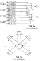
- bi-binaural synthesis consists, with reference to the figure 1a , to filter the signal of the different sound sources S i that it is desired to position, at the restitution, at a position in space, via acoustic transfer functions left HRTF-I and right HRTF-r in the frequency domain corresponding to the appropriate direction, defined in polar coordinates ( ⁇ 1 , ⁇ 1 ).
- the transfer functions HRTF for "Head Related Transfer Functions" in English, are the acoustic transfer functions of the head of the listener between the positions of the space and the auditory canal.
- HRIR for "Head Related Impulse Response” is referred to as their temporal form. These functions may further include a room effect.
- the number of necessary filters or transfer functions is then 2.N for a static binaural synthesis and 4.N for a dynamic binaural synthesis, N designating the number of sound sources or audio streams to be spatialized.
- the binaural filter implementation is generally in the form of two minimal phase filters and a pure delay, corresponding to the difference of the left and right delays applied to the ear furthest away from the source. This delay is usually implemented using a delay line.
- the minimum phase filter is a finite impulse response filter and can be executed in the time or frequency domain. Infinite impulse response filters can be searched to approximate the minimum phase HRTF filter module.
- the sound emanating from the loudspeaker Lf affects the left ear LE through an HRTF filter A but this same sound reaches the right ear RE modified by a HRTF filter B.
- the position of the speakers relative to the aforementioned HB individual may be symmetrical or not.
- Each ear therefore receives the contribution of the 5 loudspeakers in the form modeled below: O ⁇ r ⁇ e ⁇ i ⁇ l ⁇ l ⁇ e boy Wut ⁇ at ⁇ u ⁇ vs ⁇ h ⁇ e
- the filters A, B, C, D and E are modeled, most often, by linear digital filters and it is therefore necessary, in the configuration represented in FIG. figure 1b , 10 filtering functions to be applied, which can be reduced to 5, taking into account the symmetries.
- the aforementioned filtering operations can be performed in the frequency domain, for example by virtue of a fast convolution performed in the Fourier domain.
- a Fast Fourier Transform (FFT) Fourier Transform is then used to perform binauralization effectively.
- the HRTF filters A, B, C, D and E can be simplified as a frequency equalizer and a delay.
- the HRTF filter A can be realized as a simple equalizer, since it is a direct path, while the HRTF filter B includes an additional delay.
- the HRTF filters can be decomposed into a minimum phase filter and a pure delay. The delay for the ear closest to the source can be taken as zero.
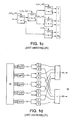
- the spatial decoding reconstruction operation of a 3D audio sound scene, from a reduced number of transmitted channels, as represented in FIG. figure 1c is also known from the state of the art.
- the configuration represented in figure 1c is that relating to the decoding of a coded sound path having location parameters in the frequency domain, in order to reconstruct a spatialized sound scene 5.1.
- the aforementioned reconstruction is carried out by a frequency subband sub-frequency decoder, as represented in FIG. figure 1c .
- the coded audio signal m undergoes 5 spatialization processing steps, which are controlled by parameters or complex coefficients of spatialization CLD and ICC calculated by the encoder and which, by means of decorrelation operations and gain correction, to realistically reconstruct the sound stage composed of six channels, the five channels represented in figure 1b , to which is added a low frequency effect channel Ife.
- a binauralization variant of the sound channels of a spatial decoder can also consist, as represented in FIG. figure 1e , converting each sound channel delivered by the audio decoder into the time domain by a synthesizer "Synth" and then performing the spatial decoding operation and binauralization, or spatialization, in the frequency domain Fourier after transformation by FFT.
- each OTT module corresponding to a matrix of decoding coefficients must then be converted into the Fourier domain, at the cost of an approximation, because the operations are not performed in the same domain.
- the complexity is further increased because the synthetic operation "Synth" is followed by three FFT transformations.
- Another solution may be to perform HRTF filtering directly in the subband domain, as shown in FIG. figure 1f .
- the HRTF filterings are complex to achieve because they require the use of subband filters, the minimum length of which is fixed and which must take into account the phenomenon of spectral folding of the subbands.
- the object of the present invention is to overcome the numerous drawbacks of the above-mentioned prior art of sound spatialization of 3 D audio scenes, in particular transauralisation or binauralization of 3 D audio scenes.
- an objective of the present invention is the execution of a specific filtering of spatially coded audio signals or channels in the frequency subband domain of a spatial decoding, in order to limit the number of transformations two by two, while reducing the filtering operations to a minimum, but maintaining a good quality of source spatialization, including transauralisation or binauralization.
- the execution of the aforementioned specific filtering is based on the equalizer-delay form of the spatialization filters, transaural or binaural, for a direct application of filtering by equalization-delay in the domain of the sub-bands.
- Another objective of the present invention is to obtain a 3D rendering quality very close to that obtained from modeling filters such as original HRTF filters, by the sole addition of a transaural spatial processing of very low complexity, following a classical spatial decoding in the transformed domain.
- an objective of the present invention is a new source spatialization technique applicable not only to the transaural or binaural rendering of a monophonic sound, but also to several monophonic sounds and in particular to the multiple channels of 5.1, 6.1, 7.1, 8.1 or 5.1 stereo sounds. higher.
- the subject of the present invention is thus a method for sound spatialisation of an audio scene comprising a first set comprising a number greater than or equal to the unit of audio channels coded spatially over a number of sub-bands of determined frequencies, and decoded in a transformed domain, in a second set comprising a number greater than or equal to two of sound reproduction channels in the time domain, from acoustic propagation modeling filters of the audio signals of the first set of channels.
- the method which is the subject of the invention is also remarkable in that the filtering by equalization-delay of the signal in sub-band includes at least the application of a phase shift and, if appropriate, a pure delay by storage, for the at least one of the frequency sub-bands.
- the method which is the subject of the invention is also remarkable in that it includes filtering by equalization-delay in a hybrid transformed domain, comprising an additional step of frequency cutting into additional subbands, with or without decimation.
- the method which is the subject of the invention is finally remarkable in that to convert each modeling filter into a gain value or a delay value in the transformed domain, it consists at least in associating as a gain value with each subband a real value. defined as the average of the modeling filter module in this sub-band and to associate as delay value with each sub-band a delay value corresponding to the reception delay between the left ear and the right ear for different positions.
- the subject of the present invention is correspondingly to a sound spatialization device of an audio scene comprising a first set comprising a number, greater than or equal to one, of audio channels coded spatially over a number of sub-bands of determined frequencies, and decoded in a transformed domain into a second set comprising a number greater than or equal to two of time domain rendering sound channels, from sound propagation modeling filters audio signals of the first subset of channels.
- the method and the device which are the subject of the invention are applicable to the electronic industry of audio and / or video hi-fi equipment, to the audio-video game industry, which is executed locally or online.
- the method according to the invention applies to an audio scene such as an audio scene 3 D represented by a first set comprising an N number of audio channels coded spatially greater than or equal to unity, N ⁇ 1, on a number of frequency subbands determined and decoded in a transformed domain.
- the transformed domain is a transformed frequency domain such as Fourier domain, PQMF domain or any hybrid domain derived from them by creating additional frequency subbands, whether or not subjected to a temporal decimation process.
- the spatially coded audio channels constituting the first set N of channels are represented in a nonlimiting manner by the channels Fl, Fr, Sr, Sl, C, Ife previously described in the description and corresponding to a decoding mode of a 3 D audio scene in the corresponding transformed domain, as previously described in the description.
- This mode is none other than the 5.1 mode previously mentioned.
- these signals are decoded in the aforementioned transformed domain according to a determined number of sub-bands suitable for decoding, the set of sub-bands being noted.
- k denotes the rank of the subband considered.
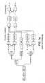
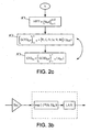
- the method which is the subject of the invention makes it possible to transform all the spatially encoded audio channels mentioned above into a second set comprising a number, greater than or equal to two, of sound reproduction channels in the time domain, the sound reproduction channels being noted Bl and Br for the left binaural channels respectively right, without limitation in the context of the figure 2a . It is understood, in particular, that instead of two binaural channels, the method which is the subject of the invention applies to any number of channels greater than two, allowing, for example, real-time sound reproduction of the 3D audio scene, as represented and described in the description in connection with the figure 1 b.
- this is implemented using acoustic propagation modeling filters of the audio signals of the first set of spatially coded audio channels, taking into account a conversion in the form of at least one gain and delay applicable in the transformed domain, as will be described later in the description.
- the modeling filters will be designated HRTF filters in the following description.
- the method according to the invention consists, for each frequency sub-band of the transformed domain of rank k, to perform a filtering in step A by equalization-delay of the signal in subband by application a gain g k respectively of a delay d k on the sub-band signal, to generate from the spatially-referenced coded channels, that is to say the channels Fl, C, Fr, Sr, Sl and Ife, an equalized and delayed component of a determined delay value in the frequency sub-band SB k of rank k.
- CED kx ⁇ Fl, C, Fr, Sr, Sl, Ife ⁇ (g kx , d kx ).
- FEB kx denotes each equalized and delayed component obtained by applying the gain g kx and the delay d kx to each of the spatially coded audio channels, ie the channels Fl, C, Fr, Sr , Sl, Ife.
- x for the corresponding rank k sub-band, can actually take the values Fl, C, Fr, Sr, Sl, Ile.
- Step A is then followed in the transformed domain of a step B of adding a subset of equalized and delayed components to create a number of filtered signals in the transformed domain corresponding to the number N 'of the second set, greater than or equal to 2, sound channels of restitution in the time domain.
- F ⁇ F1, C, Fr, Sr, S1, Ife ⁇ denotes the subset of the filtered signals in the transformed domain obtained by summation of a subset of equalized and delayed components CED kx .
- the subset of equalized and delayed components may consist of adding five of these components equalized and delayed for each ear to obtain the number N 'equal to 2 of filtered signals in the transformed domain, as will be described in more detail later in the description.
- the aforementioned addition step B is then followed by a step C of synthesizing each of the filtered signals in the transformed domain by a synthesis filter to obtain the second set of number N 'greater than or equal to two of sound signals of restitution in the time domain.
- the method that is the subject of the invention can be applied to any 3D audio scene composed of N varying from 1 to infinity of audio channels or channels coded spatially to N 'varying from 2 to the infinity of sound channels of restitution.
- step B of the figure 2a With regard to the summation step represented in step B of the figure 2a , it is indicated that this consists more specifically of adding a subset of components delayed differently by the different delays to generate the N 'components for each sub-band.
- the filtering by equalization-delay of the signal in sub-band includes at least the application of a phase shift supplemented if necessary by a pure delay by storage, for at least one sub-band. frequency bands.
- the transformed domain may, as previously mentioned in the description, correspond to a hybrid transformed domain as will be described in connection with the figure 2b in the case where no frequency decimation is applied in the corresponding sub-band.
- the delay equalization filtering represented in step A of the figure 2a is then executed in three sub-steps A1, A2, A3 represented at figure 2b .
- the step A comprises an additional step of frequency-cutting in additional sub-bands without decimation, to increase the number of applied gain values and thus the frequency accuracy, followed by a subgrouping step. additional bands to which the aforementioned gain values have been applied.
- Frequency cutting and regrouping operations are represented in substeps A 1 and A 2 of the figure 2b .
- the gain and delay values for the subband of rank k considered are subdivided into Z corresponding gain values, a gain value g kz for each additional subband and at sub-step 1 2 it is understood that the grouping of additional subbands is performed from the corresponding coded audio channels for the corresponding index x which has been applied the gain value g kz in the additional subband considered.
- the sub-step A 2 is then followed by a sub-step A 3 consisting of applying the delay to the grouped additional subbands and in particular to the spatially coded audio channels of corresponding index x via the delay d kx of similar to Step A of Fig. 2a.
- the method which is the subject of the invention can also consist in performing a filtering by equalization-delay in a hybrid transformed domain comprising an additional step of frequency cutting into additional subbands with decimation, as represented in FIG. Figure 2c .
- step A ' 1 of the Figure 2c is identical to step A 1 of the figure 2b , to execute the creation of additional subbands with decimation.
- step A ' 1 of the Figure 2c is executed in the time domain.
- Step A ' 1 is then followed by a step A' 2 corresponding to a grouping of the additional subbands to which the above-mentioned gain values have been applied in view of the decimation.
- Grouping step A ' 2 is itself preceded or followed by the application of the delay dkx thus represented by the double reversing arrow of steps A' 2 and A ' 3 .
- this operation may advantageously consist in associating, as a gain value with each subband of rank k, a real value defined as the average of the corresponding HRTF filter module and to associate, as a delay value with each subband of rank k, a delay value corresponding to the delay of propagation between the left ear and the right ear of a listener for different positions.
- each subband SB k is associated with a delay value corresponding to the propagation delay between the left ear and the right ear of a listener for different positions.
- each band is associated with a real value.
- the HRTF filter module it is possible from the HRTF filter module, to calculate, for each sub-band, the average of the module of the aforementioned HRTF filter. Such an operation is similar to an octave band or Bark analysis of HRTF filters.
- the delay to be applied for the indirect channels that is to say the delay values which are more particularly applicable to the channels whose delay is not minimum, is determined. There are many ways to automatically determine the remaining interaural delays. ITD designated for "I nteraural T ime D ifference" and correspond to the delays between the left and right ears, for different positions of the listener. The threshold method described by S.
- the most common method estimates the arrival time as the time when the HRIR time filter exceeds a given threshold.
- the arrival time may correspond to the time for which the response of the HRIR filter reaches 10% of its maximum.
- the application of a gain in the complex PQMF domain consists in multiplying the value of each sample of the subband signal, represented by a complex value, by the gain value formed by a real number.
- each sub-band SB k of each channel is thus assigned a determined gain.
- the application of a delay in the PQMF transformed domain consists, for each sample of the subband signal represented by a complex value, of introducing a rotation in the complex plane by multiplication of this sample by a complex exponential value depending on the rank of the sub-band considered, the sub-sampling rate in the sub-band considered and a delay parameter related to the interaural delay difference of a listener.
- This pure time delay is a function of the difference in the interaural delay of a listener and the sub-sampling rate in the subband considered.
- the aforementioned delays are applied to the resulting signals, ie the equalized signals and in particular to the subsets of these signals or channels which do not benefit from a direct path.
- the processing implemented therefore consists of performing a complex multiplication between an exponential complex and a subband sample formed by a complex value.
- the method which is the subject of the invention can also be implemented in a hybrid transformed domain.
- This hybrid transformed domain is a frequency domain in which the PQMF bands are advantageously redécoupées by a bank of filters decimated or not.
- the decimation means a decimation in time, so the introduction of a delay advantageously follows the procedure including a pure delay and a phase shifter.
- the delay may be applied only once during the synthesis. It is indeed useless to apply the same delay on each of the branches because the synthesis is a linear operation, without subsampling.
- the method according to the invention is repeated for at least two equalization-delay pairs and the signals obtained are summed to obtain the sound channels in the time domain.
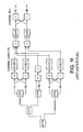
- a more detailed description of a sound spatialization device of an audio scene comprising a first set comprising a number greater than or equal to the unit of audio channels spatially coded on a number of frequency subbands determined and decoded in a domain converted, into a second set comprising a number greater than or equal to 2 of sound reproduction channels in the time domain, according to the subject of the present invention, will now be described in connection with the figures 3a and 3b .
- the device the invention is based on the principle of conversion in the form of at least one gain and a delay applicable in the transformed domain of modeling filters of the acoustic propagation of the audio signals of the first set of channels mentioned above.
- the device according to the invention allows the sound spatialization of an audio scene, such as a 3D audio scene, into a second set comprising a number, greater than or equal to two, of sound reproduction channels in the time domain.
- the device which is the subject of the invention represented in figure 3a relates in a stage of this device specific to each subband SB k of rank k decoding in the transformed domain.
- stage, for each subband of rank k represented in figure 3a is, in fact, replicated for each of the subbands to finally constitute the sound spatialization device according to the subject of the present invention.
- the device that is the subject of the invention as represented on the figure 3a comprises, in addition to the spatial decoder shown, comprising the modules OTT 0 to OTT 4 substantially corresponding to a spatial decoder SD of the prior art as represented in FIG. figure 1c , but in which, in a manner known as such, of the state of the art, a summation of the front channel C and the low frequency channel Ife by an adder S is carried out, an equalization filtering module 1 delay of the signal in subband by applying a gain respectively a delay on the signal in subband.
- the application of a gain is represented on each of the spatially coded audio channels, represented by amplifiers 1 0a to 1 8 , the latter generating an equalized component which may or may not be delayed by means of delay elements noted 1 9 to 1 12 for generating from each of the spatially coded audio channels an equalized and delayed component of a determined delay value in the frequency subband SB k .
- the gains of the amplifiers 1 0 to 1 8 have arbitrary values A, B, B, A, C, D, E, E, D respectively.
- the delay values applied by the delay modules 19 to 12 have the values Df, Bf, Ds, Ds.
- the structure of the gains and delays introduced is symmetrical. A non-symmetrical structure can be implemented without departing from the scope of the subject of the invention.
- the device according to the invention also comprises a module 2 for adding a subset of equalized and delayed components to create a number of filtered signals in the transformed domain corresponding to the number N 'of the second set greater than or equal to two sound channels of restitution in the time domain.
- the device which is the subject of the invention comprises a module 3 for synthesizing each of the filtered signals in the transformed domain to obtain the second set comprising a number N 'greater than or equal to two of sound reproduction signals in the time domain.
- the synthesis module 3 thus comprises, in the embodiment of the figure 3a , A synthesizer 3 0 3 and 1 which each can deliver a sound signal recovery in the time domain B 1 louse left binaural signal, respectively B r for right binaural signal.
- the delays introduced by the delay elements 1 9 , 1 10 , 1 11 and 1 12 are applied to the aforementioned equalized components to generate the equalized and delayed components.
- these delays are applied to the subset that does not benefit from a direct trajectory. These are, in the description of the figure 3a , the signals which have undergone the multiplications by the gains B [k] and E [k] applied by the amplifiers or multipliers 1 1 1 2 and 1 6 and 1 7 .
- the filtering element corresponding, represented in FIG. figure 3b , comprises a numerical multiplier, that is to say one of the multipliers or amplifiers 1 0 to 1 8 and represented by the gain value g kx in FIG. 3b, this multiplier allowing the multiplication of any complex sample of each encoded audio channel of index x corresponding to the channels Fl, Fr, Clfe, Sl, or Sr by a real value, that is to say the gain value previously mentioned in the description.
- the filter element represented in figure 3b includes at least one complex numerical multiplier for introducing a complex-valued rotation of any sample of the subband signal by a complex exponential value, the exp (-j ⁇ (k, SS k )) value where ⁇ (k , SS k ) denotes a phase value which is a function of the sub-sampling rate of the sub-band considered and the rank of the sub-band considered k.
- ⁇ (k, SS k ) ⁇ * ( k +0.5) * d / M.
- the complex numerical multiplier is followed by a delay line denoted by LAR introducing a pure delay of each sample after rotation, making it possible to introduce a pure time delay as a function of the difference in the interaural delay of a listener and the subsampling rate.
- M in the sub-band SB k considered.
- the resulting signals output by the summation modules 2 0 and 2 1 are subsequently passed through the synthesis filter banks 3 3 0 respectively 1 to obtain the binauralisés signals in the time domain B l B r respectively.
- the aforesaid signals can then feed a digital-to-analog converter, in order to allow the listening of sounds left B l and right B r on an audio headset for example.
- the synthesis process performed by the synthesis modules 3 0 3 1 includes, where appropriate, the hybrid synthesis process as described above in the description.
- the method which is the subject of the invention may advantageously consist in dissociating the equalization and delay operations, which may relate to frequency sub-bands in a different number.
- the equalization can for example be performed in the hybrid domain and the delay in the PQMF domain.
- the method and the device that are the subject of the invention can also be applied to effect the trans-scaling, ie the rendering of a 3d sound field on a pair of tops or to convert in an uncomplicated manner a representation of N audio channels or sound sources from a spatial decoder or from several monophonic decoders to N 'available audio channels at the rendering level.
- the filtering operations can then be multiplied if necessary.
- the method and the device which are the subject of the invention can be applied to the case of an interactive 3D game in the sounds emitted by the different objects or sound sources, which can then be spatialized as a function of their relative position in relation to the listener. Sound samples are then compressed and stored in different files or memory areas. To be played and spatialised, they are partially decoded in order to remain in the coded domain and are filtered in the coded domain by suitable binaural filters advantageously using the writing method according to the object of the present invention.
- the invention finally covers a computer program comprising a sequence of instructions stored on a storage medium for execution by a computer or a dedicated sound spatialization device, which during this execution performs the addition filtering and as described in connection with the Figures 2a to 2c and 3a, 3b previously in the description.
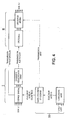
- a first spatial coding and rate reduction coding unit I is considered, including a device that is the subject of the invention as represented in FIG. figure 3a , 3b , making it possible to operate the above-mentioned spatial coding from an audio scene in 5.1 mode for example and the coded audio transmission, on the one hand, and spatial parameters, on the other hand, to a decoding and decoding unit spatial II.
- the calculation of the delay equalization filters can then be performed by a separate unit III, which from the modeling filters, HRTF filters, calculates the gain and delay equalization values and transmits them to the coding unit I. spatial and spatial decoding unit II.
- Spatial coding can thus take into account the HRTFs that will be applied to correct its spatial parameters and improve 3D rendering.
- the rate reduction encoder can use these HRTFs to measure the perceptual effects of frequency quantization.
- the process implemented by the device and method of the invention thus makes it possible to carry out a sound spatialization of an audio scene in which the first set comprises a determined number of spatially coded audio channels and the second set comprises a lower number of sound reproduction channels in the time domain. It also allows decoding to perform an inverse transformation of a number of spatially coded audio channels to a set having a greater or equal number of time domain rendering sound channels.
Landscapes
- Engineering & Computer Science (AREA)
- Physics & Mathematics (AREA)
- Acoustics & Sound (AREA)
- Signal Processing (AREA)
- Multimedia (AREA)
- General Physics & Mathematics (AREA)
- Algebra (AREA)
- Mathematical Analysis (AREA)
- Mathematical Optimization (AREA)
- Mathematical Physics (AREA)
- Pure & Applied Mathematics (AREA)
- Theoretical Computer Science (AREA)
- Stereophonic System (AREA)
Claims (17)
- Verfahren zur akustischen Verräumlichung einer Audioszene, die eine erste Einheit aufweist, welche eine Anzahl, größer als der oder gleich dem Einheitswert, von Audiokanälen enthält, die räumlich über eine bestimmte Anzahl von Frequenz-Unterbändern codiert sind und in einem transformierten Bereich decodiert werden, in eine zweiten Einheit, die eine Anzahl größer als oder gleich zwei von Wiedergabe-Tonkanälen im Zeitbereich enthält, ausgehend von Modellierungsfiltern der akustischen Ausbreitung der Audiosignale der ersten Einheit von Kanälen, dadurch gekennzeichnet, dass für jedes Modellierungsfilter, das in Form mindestens einer Verstärkung und einer Verzögerung konvertiert ist, die im transformierten Bereich anwendbar sind, das Verfahren für jedes Frequenz-Unterband des transformierten Bereichs mindestens umfasst:- die Filterung durch Entzerrung-Verzögerung des Unterband-Signals durch Anwendung einer Verstärkung bzw. einer Verzögerung an das Unterband-Signal, um ausgehend von den räumlich codierten Kanälen eine Komponente zu erzeugen, die entzerrt und um einen Verzögerungswert verzögert ist, der im betrachteten Frequenz-Unterband bestimmt wird;- die Hinzufügung einer Untereinheit von entzerrten und verzögerten Komponenten, um eine Anzahl von gefilterten Signalen im transformierten Bereich zu erzeugen, die der Anzahl der zweiten Einheit größer als oder gleich zwei von Wiedergabe-Tonkanälen im Zeitbereich entspricht;- die Synthese jedes der gefilterten Signale im transformierten Bereich durch ein Synthesefilter, um die zweite Einheit einer Anzahl größer als oder gleich zwei von Wiedergabe-Tonkanälen im Zeitbereich zu erhalten.
- Verfahren nach Anspruch 1, dadurch gekennzeichnet, dass die Filterung durch Entzerrung-Verzögerung des Unterband-Signals mindestens die Anwendung einer Phasenverschiebung für mindestens eines der Frequenz-Unterbänder umfasst.
- Verfahren nach Anspruch 2, dadurch gekennzeichnet, dass die Filterung durch Entzerrung-Verzögerung außerdem eine reine Verzögerung durch Speicherung für mindestens eines der Frequenz-Unterbänder umfasst.
- Verfahren nach einem der Ansprüche 1 bis 3, dadurch gekennzeichnet, dass die Filterung durch Entzerrung-Verzögerung in einem hybriden transformierten Bereich einen zusätzlichen Schritt der Frequenzzerlegung in zusätzliche Unterbänder ohne Frequenzherabsetzung aufweist, um die Anzahl von angewendeten Verstärkungswerten zu erhöhen, gefolgt von einem Schritt der Zusammenfassung der zusätzlichen Unterbänder, an die die Verstärkungswerte angewendet wurden, dann Anwendung der Verzögerung.
- Verfahren nach einem der Ansprüche 1 bis 3, dadurch gekennzeichnet, dass die Filterung durch Entzerrung-Verzögerung in einem hybriden transformierten Bereich einen zusätzlichen Schritt der Frequenzzerlegung in zusätzliche Unterbänder mit Frequenzherabsetzung aufweist, um die Anzahl von angewendeten Verstärkungswerten zu erhöhen, gefolgt von einem Schritt der Zusammenfassung der zusätzlichen Unterbänder, an die die Verstärkungswerte angewendet wurden, wobei die Anwendung der Verzögerung vor oder nach dem Schritt der Zusammenfassung selbst liegt.
- Verfahren nach einem der vorhergehenden Ansprüche, dadurch gekennzeichnet, dass, um jedes Modellierungsfilter in einen Verstärkungs- bzw. Verzögerungswert im transformierten Bereich zu konvertieren, dieses mindestens darin besteht:- als Verstärkungswert jedem Unterband einen realen Wert zuzuordnen, der als der Mittelwert des Moduls des Modellierungsfilters definiert wird;- als Verzögerungswert jedem Unterband einen Verzögerungswert entsprechend der Ausbreitungsverzögerung zwischen dem linken Ohr und dem rechten Ohr für verschiedene Stellungen zuzuordnen.
- Verfahren nach einem der Ansprüche 1 bis 3 oder 6, ausschließlich der Ansprüche 4 oder 5, dadurch gekennzeichnet, dass die Anwendung einer Verstärkung im PQMF-Bereich darin besteht, den Wert jeder Tastprobe des Unterband-Signals, dargestellt durch einen komplexen Wert, mit dem von einer realen Zahl geformten Verstärkungswert zu multiplizieren.
- Verfahren nach einem der Ansprüche 1 bis 3 oder 6 oder 7, ausschließlich der Ansprüche 4 oder 5, dadurch gekennzeichnet, dass die Anwendung einer Verzögerung im transformierten PQMF-Bereich für jede Tastprobe des Unterband-Signals, dargestellt durch einen komplexen Wert, mindestens darin besteht:- eine Rotation in der komplexen Ebene durch Multiplizieren dieser Tastprobe mit einem komplexen Exponentialwert abhängig vom Rang des betrachteten Unterbands, vom Unterabtastungsgrad im betrachteten Unterband und von einem Verzögerungsparameter verbunden mit der interauralen Verzögerungsdifferenz eines Hörers einzuführen;- eine reine Zeitverzögerung der Tastprobe nach Rotation einzuführen, wobei die reine Zeitverzögerung eine Funktion der Differenz der interauralen Verzögerung eines Hörers und des Unterabtastungsgrads im betrachteten Unterband ist.
- Verfahren nach einem der Ansprüche 1 bis 8, dadurch gekennzeichnet, dass für eine binaurale akustische Verräumlichung einer Audioszene, bei der die erste Einheit eine Anzahl von räumlich codierten Kanälen gleich N=6 im Modus 5.1 aufweist, die zweite Einheit zwei Wiedergabe-Tonkanäle im Zeitbereich für eine Wiedergabe durch einen Audio-Kopfhörer aufweist.
- Verfahren nach einem der Ansprüche 1 bis 9, dadurch gekennzeichnet, dass das Verfahren für mindestens zwei Entzerrungs-Verzögerungs-Paare wiederholt wird und die erhaltenen Signale summiert werden, um die Tonkanäle im Zeitbereich zu erhalten.
- Verfahren nach einem der Ansprüche 1 bis 9, dadurch gekennzeichnet, dass für eine akustische Verräumlichung einer Audioszene, bei der die erste Einheit eine bestimmte Anzahl von räumlich codierten Audiokanälen und die zweite Einheit eine geringere Anzahl von Wiedergabe-Tonkanälen im Zeitbereich aufweist, dieses Verfahren beim Decodieren darin besteht, eine umgekehrte Transformation einer Anzahl von räumlich codierten Tonkanälen in eine Einheit durchzuführen, die eine höhere oder gleiche Anzahl von Wiedergabe-Tonkanälen im Zeitbereich aufweist.
- Verfahren nach einem der vorhergehenden Ansprüche, dadurch gekennzeichnet, dass die dem Modellierungsfilter zugeordneten Verstärkungs- und Verzögerungswerte in quantifizierter Form übertragen werden.
- Vorrichtung zur akustischen Verräumlichung einer Audioszene, die eine erste Einheit aufweist, welche eine Anzahl, größer als der oder gleich dem Einheitswert, von Audiokanälen aufweist, die räumlich auf eine bestimmte Anzahl von Frequenz-Unterbändern codiert sind und in einem transformierten Bereich decodiert werden, in eine zweiten Einheit, die eine Anzahl größer als oder gleich zwei von Wiedergabe-Tonkanälen im Zeitbereich enthält, ausgehend von Modellierungsfiltern der akustischen Ausbreitung der Audiosignale der ersten Einheit von Kanälen, dadurch gekennzeichnet, dass für jedes Frequenz-Unterband eines räumlichen Decodierers im transformierten Bereich die Vorrichtung außer diesem räumlichen Decodierer enthält:- Einrichtungen zur Filterung durch Entzerrung-Verzögerung des Unterband-Signals durch Anwendung mindestens einer Verstärkung bzw. einer Verzögerung an das Unterband-Signal, um ausgehend von jedem der räumlich codierten Audiokanäle eine entzerrte und verzögerte Komponente eines bestimmten Verzögerungswerts im betrachteten Frequenz-Unterband zu erzeugen;- Einrichtungen zum Hinzufügen einer Untereinheit von entzerrten und verzögerten Komponenten, um eine Anzahl von gefilterten Signalen im transformierten Bereich zu erzeugen, die der Anzahl der zweiten Einheit größer als oder gleich zwei von Wiedergabe-Tonkanälen im Zeitbereich entspricht;- Einrichtungen zur Synthese jedes der gefilterten Signale im transformierten Bereich, um die zweite Einheit zu erhalten, die eine Anzahl höher als oder gleich zwei Wiedergabe-Tonsignalen im Zeitbereich enthält.
- Vorrichtung nach Anspruch 13, dadurch gekennzeichnet, dass die Einrichtungen zur Filterung durch Anwendung einer Verstärkung einen digitalen Multiplikator jeder komplexen Tastprobe jedes räumlich codierten Audiokanals mit einem realen Wert aufweisen.
- Vorrichtung nach Anspruch 13 oder 14, dadurch gekennzeichnet, dass die Einrichtungen zur Filterung durch Anwendung einer Verzögerung mindestens einen komplexen digitalen Multiplikator aufweisen, der es ermöglicht, eine Rotation in der komplexen Ebene jeder Tastprobe des Unterband-Signals um einen komplexen Exponentialwert, abhängig vom Rang des betrachteten Unterbands, vom Unterabtastungsgrad im betrachteten Unterband und von einem Verzögerungsparameter, der mit der interauralen Verzögerungsdifferenz eines Hörers verbunden ist, einzuführen.
- Vorrichtung nach Anspruch 15, dadurch gekennzeichnet, dass die Filtereinrichtungen außerdem eine reine Verzögerungsleitung jeder Tastprobe nach Rotation aufweisen, die es ermöglicht, eine reine Zeitverzögerung abhängig von der Differenz der interauralen Verzögerung eines Hörers und vom Unterabtastungsgrad im betrachteten Unterband einzuführen.
- Computerprogramm, das eine Folge von auf einem Speicherträger gespeicherten Anweisungen für die Ausführung durch einen Computer oder eine dedizierte Vorrichtung enthält, dadurch gekennzeichnet, dass bei dieser Ausführung das Programm die Schritte der Filterung, des Hinzufügens und der Synthese nach einem der Ansprüche 1 bis 12 durchführt.
Priority Applications (1)
| Application Number | Priority Date | Filing Date | Title |
|---|---|---|---|
| PL07731710T PL2000002T3 (pl) | 2006-03-28 | 2007-03-08 | Sposób i urządzenie do efektywnego dwuusznego uprzestrzenniania dźwięku w dziedzinie transformowanej |
Applications Claiming Priority (2)
| Application Number | Priority Date | Filing Date | Title |
|---|---|---|---|
| FR0602685A FR2899423A1 (fr) | 2006-03-28 | 2006-03-28 | Procede et dispositif de spatialisation sonore binaurale efficace dans le domaine transforme. |
| PCT/FR2007/050894 WO2007110519A2 (fr) | 2006-03-28 | 2007-03-08 | Procede et dispositif de spatialisation sonore binaurale efficace dans le domaine transforme |
Publications (2)
| Publication Number | Publication Date |
|---|---|
| EP2000002A2 EP2000002A2 (de) | 2008-12-10 |
| EP2000002B1 true EP2000002B1 (de) | 2009-08-05 |
Family
ID=37649439
Family Applications (1)
| Application Number | Title | Priority Date | Filing Date |
|---|---|---|---|
| EP07731710A Active EP2000002B1 (de) | 2006-03-28 | 2007-03-08 | Verfahren und einrichtung zur effizienten binauralen raumklangerzeugung im transformierten bereich |
Country Status (12)
| Country | Link |
|---|---|
| US (1) | US8605909B2 (de) |
| EP (1) | EP2000002B1 (de) |
| JP (1) | JP5090436B2 (de) |
| KR (1) | KR101325644B1 (de) |
| CN (1) | CN101455095B (de) |
| AT (1) | ATE439013T1 (de) |
| BR (1) | BRPI0709276B1 (de) |
| DE (1) | DE602007001877D1 (de) |
| ES (1) | ES2330274T3 (de) |
| FR (1) | FR2899423A1 (de) |
| PL (1) | PL2000002T3 (de) |
| WO (1) | WO2007110519A2 (de) |
Families Citing this family (27)
| Publication number | Priority date | Publication date | Assignee | Title |
|---|---|---|---|---|
| KR101218776B1 (ko) | 2006-01-11 | 2013-01-18 | 삼성전자주식회사 | 다운믹스된 신호로부터 멀티채널 신호 생성방법 및 그 기록매체 |
| US8027479B2 (en) * | 2006-06-02 | 2011-09-27 | Coding Technologies Ab | Binaural multi-channel decoder in the context of non-energy conserving upmix rules |
| JP5325108B2 (ja) * | 2006-10-13 | 2013-10-23 | ギャラクシー ステューディオス エヌヴェー | デジタルデータ集合を結合するための方法及び符号器、結合デジタルデータ集合の復号方法及び復号器、並びに結合デジタルデータ集合を記憶するための記録媒体 |
| KR101464977B1 (ko) * | 2007-10-01 | 2014-11-25 | 삼성전자주식회사 | 메모리 관리 방법, 및 멀티 채널 데이터의 복호화 방법 및장치 |
| KR100954385B1 (ko) * | 2007-12-18 | 2010-04-26 | 한국전자통신연구원 | 개인화된 머리전달함수를 이용한 3차원 오디오 신호 처리장치 및 그 방법과, 그를 이용한 고현장감 멀티미디어 재생시스템 |
| FR2938947B1 (fr) * | 2008-11-25 | 2012-08-17 | A Volute | Procede de traitement du signal, notamment audionumerique. |
| FR2969804A1 (fr) * | 2010-12-23 | 2012-06-29 | France Telecom | Filtrage perfectionne dans le domaine transforme. |
| WO2014015914A1 (en) * | 2012-07-27 | 2014-01-30 | Fraunhofer-Gesellschaft zur Förderung der angewandten Forschung e.V. | Apparatus and method for providing a loudspeaker-enclosure-microphone system description |
| CN109166588B (zh) * | 2013-01-15 | 2022-11-15 | 韩国电子通信研究院 | 处理信道信号的编码/解码装置及方法 |
| CN104010264B (zh) * | 2013-02-21 | 2016-03-30 | 中兴通讯股份有限公司 | 双声道音频信号处理的方法和装置 |
| KR101815082B1 (ko) * | 2013-09-17 | 2018-01-04 | 주식회사 윌러스표준기술연구소 | 멀티미디어 신호 처리 방법 및 장치 |
| US9067135B2 (en) | 2013-10-07 | 2015-06-30 | Voyetra Turtle Beach, Inc. | Method and system for dynamic control of game audio based on audio analysis |
| US9716958B2 (en) | 2013-10-09 | 2017-07-25 | Voyetra Turtle Beach, Inc. | Method and system for surround sound processing in a headset |
| US9143878B2 (en) * | 2013-10-09 | 2015-09-22 | Voyetra Turtle Beach, Inc. | Method and system for headset with automatic source detection and volume control |
| US9338541B2 (en) | 2013-10-09 | 2016-05-10 | Voyetra Turtle Beach, Inc. | Method and system for in-game visualization based on audio analysis |
| US10063982B2 (en) | 2013-10-09 | 2018-08-28 | Voyetra Turtle Beach, Inc. | Method and system for a game headset with audio alerts based on audio track analysis |
| US8979658B1 (en) | 2013-10-10 | 2015-03-17 | Voyetra Turtle Beach, Inc. | Dynamic adjustment of game controller sensitivity based on audio analysis |
| CN104681034A (zh) | 2013-11-27 | 2015-06-03 | 杜比实验室特许公司 | 音频信号处理 |
| KR101627657B1 (ko) * | 2013-12-23 | 2016-06-07 | 주식회사 윌러스표준기술연구소 | 오디오 신호의 필터 생성 방법 및 이를 위한 파라메터화 장치 |
| KR101856127B1 (ko) * | 2014-04-02 | 2018-05-09 | 주식회사 윌러스표준기술연구소 | 오디오 신호 처리 방법 및 장치 |
| US10142755B2 (en) * | 2016-02-18 | 2018-11-27 | Google Llc | Signal processing methods and systems for rendering audio on virtual loudspeaker arrays |
| DE202017102729U1 (de) * | 2016-02-18 | 2017-06-27 | Google Inc. | Signalverarbeitungssysteme zur Wiedergabe von Audiodaten auf virtuellen Lautsprecher-Arrays |
| CN106412793B (zh) * | 2016-09-05 | 2018-06-12 | 中国科学院自动化研究所 | 基于球谐函数的头相关传输函数的稀疏建模方法和系统 |
| US10313819B1 (en) * | 2018-06-18 | 2019-06-04 | Bose Corporation | Phantom center image control |
| CN109166592B (zh) * | 2018-08-08 | 2023-04-18 | 西北工业大学 | 基于生理参数的hrtf分频段线性回归方法 |
| EP4085660A4 (de) | 2019-12-30 | 2024-05-22 | Comhear Inc. | Verfahren zum bereitstellen eines räumlichen schallfeldes |
| CN112437392B (zh) * | 2020-12-10 | 2022-04-19 | 科大讯飞(苏州)科技有限公司 | 声场重建方法、装置、电子设备和存储介质 |
Family Cites Families (13)
| Publication number | Priority date | Publication date | Assignee | Title |
|---|---|---|---|---|
| JP2755081B2 (ja) * | 1992-11-30 | 1998-05-20 | 日本ビクター株式会社 | 音像定位制御方法 |
| JP2001306097A (ja) * | 2000-04-26 | 2001-11-02 | Matsushita Electric Ind Co Ltd | 音声符号化方式及び装置、音声復号化方式及び装置、並びに記録媒体 |
| JP3624884B2 (ja) * | 2001-12-28 | 2005-03-02 | ヤマハ株式会社 | 音声データ処理装置 |
| JP2003230198A (ja) * | 2002-02-01 | 2003-08-15 | Matsushita Electric Ind Co Ltd | 音像定位制御装置 |
| JP2004023486A (ja) * | 2002-06-17 | 2004-01-22 | Arnis Sound Technologies Co Ltd | ヘッドホンによる再生音聴取における音像頭外定位方法、及び、そのための装置 |
| RU2325046C2 (ru) | 2002-07-16 | 2008-05-20 | Конинклейке Филипс Электроникс Н.В. | Аудиокодирование |
| FR2851879A1 (fr) * | 2003-02-27 | 2004-09-03 | France Telecom | Procede de traitement de donnees sonores compressees, pour spatialisation. |
| CN1886780A (zh) * | 2003-12-15 | 2006-12-27 | 法国电信 | 声音合成和空间化方法 |
| US7805313B2 (en) * | 2004-03-04 | 2010-09-28 | Agere Systems Inc. | Frequency-based coding of channels in parametric multi-channel coding systems |
| KR100644617B1 (ko) * | 2004-06-16 | 2006-11-10 | 삼성전자주식회사 | 7.1 채널 오디오 재생 방법 및 장치 |
| US7391870B2 (en) | 2004-07-09 | 2008-06-24 | Fraunhofer-Gesellschaft Zur Foerderung Der Angewandten Forschung E V | Apparatus and method for generating a multi-channel output signal |
| US7853022B2 (en) * | 2004-10-28 | 2010-12-14 | Thompson Jeffrey K | Audio spatial environment engine |
| CN101401455A (zh) * | 2006-03-15 | 2009-04-01 | 杜比实验室特许公司 | 使用子带滤波器的立体声呈现技术 |
-
2006
- 2006-03-28 FR FR0602685A patent/FR2899423A1/fr not_active Withdrawn
-
2007
- 2007-03-08 ES ES07731710T patent/ES2330274T3/es active Active
- 2007-03-08 KR KR1020087026354A patent/KR101325644B1/ko active Active
- 2007-03-08 JP JP2009502159A patent/JP5090436B2/ja active Active
- 2007-03-08 US US12/225,677 patent/US8605909B2/en active Active
- 2007-03-08 CN CN200780020028XA patent/CN101455095B/zh active Active
- 2007-03-08 AT AT07731710T patent/ATE439013T1/de not_active IP Right Cessation
- 2007-03-08 WO PCT/FR2007/050894 patent/WO2007110519A2/fr not_active Ceased
- 2007-03-08 DE DE602007001877T patent/DE602007001877D1/de active Active
- 2007-03-08 PL PL07731710T patent/PL2000002T3/pl unknown
- 2007-03-08 EP EP07731710A patent/EP2000002B1/de active Active
- 2007-03-08 BR BRPI0709276-8A patent/BRPI0709276B1/pt active IP Right Grant
Also Published As
| Publication number | Publication date |
|---|---|
| PL2000002T3 (pl) | 2010-01-29 |
| CN101455095A (zh) | 2009-06-10 |
| EP2000002A2 (de) | 2008-12-10 |
| ES2330274T3 (es) | 2009-12-07 |
| US20090232317A1 (en) | 2009-09-17 |
| US8605909B2 (en) | 2013-12-10 |
| CN101455095B (zh) | 2011-03-30 |
| KR20080109889A (ko) | 2008-12-17 |
| DE602007001877D1 (de) | 2009-09-17 |
| JP2009531905A (ja) | 2009-09-03 |
| ATE439013T1 (de) | 2009-08-15 |
| WO2007110519A3 (fr) | 2007-11-15 |
| BRPI0709276A2 (pt) | 2011-07-12 |
| WO2007110519A2 (fr) | 2007-10-04 |
| BRPI0709276B1 (pt) | 2019-10-08 |
| KR101325644B1 (ko) | 2013-11-06 |
| JP5090436B2 (ja) | 2012-12-05 |
| FR2899423A1 (fr) | 2007-10-05 |
Similar Documents
| Publication | Publication Date | Title |
|---|---|---|
| EP2000002B1 (de) | Verfahren und einrichtung zur effizienten binauralen raumklangerzeugung im transformierten bereich | |
| EP1999998B1 (de) | Verfahren zur binauralen synthese unter berücksichtigung eines raumeffekts | |
| EP1992198B1 (de) | Optimierung des binauralen raumklangeffektes durch mehrkanalkodierung | |
| EP1600042B1 (de) | Verfahren zum bearbeiten komprimierter audiodaten zur räumlichen wiedergabe | |
| EP2042001B1 (de) | Binaurale spatialisierung kompressionsverschlüsselter tondaten | |
| FR2995754A1 (fr) | Calibration optimisee d'un systeme de restitution sonore multi haut-parleurs | |
| JP7726972B2 (ja) | スペクトル直交オーディオ成分を用いたサブバンド空間処理およびクロストーク処理 | |
| FR3065137A1 (fr) | Procede de spatialisation sonore | |
| US20160212564A1 (en) | Apparatus and Method for Compressing a Set of N Binaural Room Impulse Responses | |
| EP3025514B1 (de) | Klangverräumlichung mit raumwirkung | |
| EP1994526B1 (de) | Gemeinsame schallsynthese und -spatialisierung | |
| EP3058564B1 (de) | Komplexitätsoptimierte klangverräumlichung mit nachhall | |
| EP3449643B1 (de) | Verfahren und system zum senden eines 360°-audiosignals |
Legal Events
| Date | Code | Title | Description |
|---|---|---|---|
| PUAI | Public reference made under article 153(3) epc to a published international application that has entered the european phase |
Free format text: ORIGINAL CODE: 0009012 |
|
| 17P | Request for examination filed |
Effective date: 20080922 |
|
| AK | Designated contracting states |
Kind code of ref document: A2 Designated state(s): AT BE BG CH CY CZ DE DK EE ES FI FR GB GR HU IE IS IT LI LT LU LV MC MT NL PL PT RO SE SI SK TR |
|
| GRAP | Despatch of communication of intention to grant a patent |
Free format text: ORIGINAL CODE: EPIDOSNIGR1 |
|
| GRAS | Grant fee paid |
Free format text: ORIGINAL CODE: EPIDOSNIGR3 |
|
| GRAA | (expected) grant |
Free format text: ORIGINAL CODE: 0009210 |
|
| AK | Designated contracting states |
Kind code of ref document: B1 Designated state(s): AT BE BG CH CY CZ DE DK EE ES FI FR GB GR HU IE IS IT LI LT LU LV MC MT NL PL PT RO SE SI SK TR |
|
| REG | Reference to a national code |
Ref country code: GB Ref legal event code: FG4D Free format text: NOT ENGLISH |
|
| REG | Reference to a national code |
Ref country code: CH Ref legal event code: EP |
|
| REG | Reference to a national code |
Ref country code: IE Ref legal event code: FG4D |
|
| REF | Corresponds to: |
Ref document number: 602007001877 Country of ref document: DE Date of ref document: 20090917 Kind code of ref document: P |
|
| REG | Reference to a national code |
Ref country code: ES Ref legal event code: FG2A Ref document number: 2330274 Country of ref document: ES Kind code of ref document: T3 |
|
| LTIE | Lt: invalidation of european patent or patent extension |
Effective date: 20090805 |
|
| PG25 | Lapsed in a contracting state [announced via postgrant information from national office to epo] |
Ref country code: LT Free format text: LAPSE BECAUSE OF FAILURE TO SUBMIT A TRANSLATION OF THE DESCRIPTION OR TO PAY THE FEE WITHIN THE PRESCRIBED TIME-LIMIT Effective date: 20090805 Ref country code: SE Free format text: LAPSE BECAUSE OF FAILURE TO SUBMIT A TRANSLATION OF THE DESCRIPTION OR TO PAY THE FEE WITHIN THE PRESCRIBED TIME-LIMIT Effective date: 20090805 Ref country code: AT Free format text: LAPSE BECAUSE OF FAILURE TO SUBMIT A TRANSLATION OF THE DESCRIPTION OR TO PAY THE FEE WITHIN THE PRESCRIBED TIME-LIMIT Effective date: 20090805 Ref country code: FI Free format text: LAPSE BECAUSE OF FAILURE TO SUBMIT A TRANSLATION OF THE DESCRIPTION OR TO PAY THE FEE WITHIN THE PRESCRIBED TIME-LIMIT Effective date: 20090805 Ref country code: IS Free format text: LAPSE BECAUSE OF FAILURE TO SUBMIT A TRANSLATION OF THE DESCRIPTION OR TO PAY THE FEE WITHIN THE PRESCRIBED TIME-LIMIT Effective date: 20091205 |
|
| REG | Reference to a national code |
Ref country code: PL Ref legal event code: T3 |
|
| NLV1 | Nl: lapsed or annulled due to failure to fulfill the requirements of art. 29p and 29m of the patents act | ||
| PG25 | Lapsed in a contracting state [announced via postgrant information from national office to epo] |
Ref country code: SI Free format text: LAPSE BECAUSE OF FAILURE TO SUBMIT A TRANSLATION OF THE DESCRIPTION OR TO PAY THE FEE WITHIN THE PRESCRIBED TIME-LIMIT Effective date: 20090805 Ref country code: LV Free format text: LAPSE BECAUSE OF FAILURE TO SUBMIT A TRANSLATION OF THE DESCRIPTION OR TO PAY THE FEE WITHIN THE PRESCRIBED TIME-LIMIT Effective date: 20090805 Ref country code: NL Free format text: LAPSE BECAUSE OF FAILURE TO SUBMIT A TRANSLATION OF THE DESCRIPTION OR TO PAY THE FEE WITHIN THE PRESCRIBED TIME-LIMIT Effective date: 20090805 |
|
| REG | Reference to a national code |
Ref country code: IE Ref legal event code: FD4D |
|
| PG25 | Lapsed in a contracting state [announced via postgrant information from national office to epo] |
Ref country code: BG Free format text: LAPSE BECAUSE OF FAILURE TO SUBMIT A TRANSLATION OF THE DESCRIPTION OR TO PAY THE FEE WITHIN THE PRESCRIBED TIME-LIMIT Effective date: 20091105 Ref country code: PT Free format text: LAPSE BECAUSE OF FAILURE TO SUBMIT A TRANSLATION OF THE DESCRIPTION OR TO PAY THE FEE WITHIN THE PRESCRIBED TIME-LIMIT Effective date: 20091205 |
|
| PG25 | Lapsed in a contracting state [announced via postgrant information from national office to epo] |
Ref country code: DK Free format text: LAPSE BECAUSE OF FAILURE TO SUBMIT A TRANSLATION OF THE DESCRIPTION OR TO PAY THE FEE WITHIN THE PRESCRIBED TIME-LIMIT Effective date: 20090805 Ref country code: EE Free format text: LAPSE BECAUSE OF FAILURE TO SUBMIT A TRANSLATION OF THE DESCRIPTION OR TO PAY THE FEE WITHIN THE PRESCRIBED TIME-LIMIT Effective date: 20090805 Ref country code: CZ Free format text: LAPSE BECAUSE OF FAILURE TO SUBMIT A TRANSLATION OF THE DESCRIPTION OR TO PAY THE FEE WITHIN THE PRESCRIBED TIME-LIMIT Effective date: 20090805 Ref country code: RO Free format text: LAPSE BECAUSE OF FAILURE TO SUBMIT A TRANSLATION OF THE DESCRIPTION OR TO PAY THE FEE WITHIN THE PRESCRIBED TIME-LIMIT Effective date: 20090805 Ref country code: IE Free format text: LAPSE BECAUSE OF FAILURE TO SUBMIT A TRANSLATION OF THE DESCRIPTION OR TO PAY THE FEE WITHIN THE PRESCRIBED TIME-LIMIT Effective date: 20090805 |
|
| PG25 | Lapsed in a contracting state [announced via postgrant information from national office to epo] |
Ref country code: SK Free format text: LAPSE BECAUSE OF FAILURE TO SUBMIT A TRANSLATION OF THE DESCRIPTION OR TO PAY THE FEE WITHIN THE PRESCRIBED TIME-LIMIT Effective date: 20090805 |
|
| PLBE | No opposition filed within time limit |
Free format text: ORIGINAL CODE: 0009261 |
|
| STAA | Information on the status of an ep patent application or granted ep patent |
Free format text: STATUS: NO OPPOSITION FILED WITHIN TIME LIMIT |
|
| 26N | No opposition filed |
Effective date: 20100507 |
|
| BERE | Be: lapsed |
Owner name: FRANCE TELECOM Effective date: 20100331 |
|
| PG25 | Lapsed in a contracting state [announced via postgrant information from national office to epo] |
Ref country code: MC Free format text: LAPSE BECAUSE OF NON-PAYMENT OF DUE FEES Effective date: 20100331 Ref country code: GR Free format text: LAPSE BECAUSE OF FAILURE TO SUBMIT A TRANSLATION OF THE DESCRIPTION OR TO PAY THE FEE WITHIN THE PRESCRIBED TIME-LIMIT Effective date: 20091106 |
|
| PG25 | Lapsed in a contracting state [announced via postgrant information from national office to epo] |
Ref country code: BE Free format text: LAPSE BECAUSE OF NON-PAYMENT OF DUE FEES Effective date: 20100331 |
|
| PG25 | Lapsed in a contracting state [announced via postgrant information from national office to epo] |
Ref country code: MT Free format text: LAPSE BECAUSE OF FAILURE TO SUBMIT A TRANSLATION OF THE DESCRIPTION OR TO PAY THE FEE WITHIN THE PRESCRIBED TIME-LIMIT Effective date: 20090805 |
|
| PGRI | Patent reinstated in contracting state [announced from national office to epo] |
Ref country code: IT Effective date: 20110501 |
|
| PGRI | Patent reinstated in contracting state [announced from national office to epo] |
Ref country code: IT Effective date: 20110501 |
|
| REG | Reference to a national code |
Ref country code: CH Ref legal event code: PL |
|
| PG25 | Lapsed in a contracting state [announced via postgrant information from national office to epo] |
Ref country code: LI Free format text: LAPSE BECAUSE OF NON-PAYMENT OF DUE FEES Effective date: 20110331 Ref country code: CH Free format text: LAPSE BECAUSE OF NON-PAYMENT OF DUE FEES Effective date: 20110331 |
|
| PG25 | Lapsed in a contracting state [announced via postgrant information from national office to epo] |
Ref country code: CY Free format text: LAPSE BECAUSE OF FAILURE TO SUBMIT A TRANSLATION OF THE DESCRIPTION OR TO PAY THE FEE WITHIN THE PRESCRIBED TIME-LIMIT Effective date: 20090805 |
|
| PG25 | Lapsed in a contracting state [announced via postgrant information from national office to epo] |
Ref country code: HU Free format text: LAPSE BECAUSE OF FAILURE TO SUBMIT A TRANSLATION OF THE DESCRIPTION OR TO PAY THE FEE WITHIN THE PRESCRIBED TIME-LIMIT Effective date: 20100206 Ref country code: LU Free format text: LAPSE BECAUSE OF NON-PAYMENT OF DUE FEES Effective date: 20100308 |
|
| PG25 | Lapsed in a contracting state [announced via postgrant information from national office to epo] |
Ref country code: TR Free format text: LAPSE BECAUSE OF FAILURE TO SUBMIT A TRANSLATION OF THE DESCRIPTION OR TO PAY THE FEE WITHIN THE PRESCRIBED TIME-LIMIT Effective date: 20090805 |
|
| REG | Reference to a national code |
Ref country code: FR Ref legal event code: PLFP Year of fee payment: 9 |
|
| REG | Reference to a national code |
Ref country code: FR Ref legal event code: PLFP Year of fee payment: 10 |
|
| REG | Reference to a national code |
Ref country code: FR Ref legal event code: PLFP Year of fee payment: 11 |
|
| REG | Reference to a national code |
Ref country code: FR Ref legal event code: PLFP Year of fee payment: 12 |
|
| PGFP | Annual fee paid to national office [announced via postgrant information from national office to epo] |
Ref country code: DE Payment date: 20250218 Year of fee payment: 19 |
|
| PGFP | Annual fee paid to national office [announced via postgrant information from national office to epo] |
Ref country code: PL Payment date: 20250225 Year of fee payment: 19 Ref country code: FR Payment date: 20250219 Year of fee payment: 19 |
|
| PGFP | Annual fee paid to national office [announced via postgrant information from national office to epo] |
Ref country code: IT Payment date: 20250218 Year of fee payment: 19 Ref country code: GB Payment date: 20250221 Year of fee payment: 19 |
|
| PGFP | Annual fee paid to national office [announced via postgrant information from national office to epo] |
Ref country code: ES Payment date: 20250401 Year of fee payment: 19 |