EP1998604B1 - Wendewerkzeug für landwirtschaftliche untergrundpflüge und dergleichen - Google Patents
Wendewerkzeug für landwirtschaftliche untergrundpflüge und dergleichen Download PDFInfo
- Publication number
- EP1998604B1 EP1998604B1 EP07723732A EP07723732A EP1998604B1 EP 1998604 B1 EP1998604 B1 EP 1998604B1 EP 07723732 A EP07723732 A EP 07723732A EP 07723732 A EP07723732 A EP 07723732A EP 1998604 B1 EP1998604 B1 EP 1998604B1
- Authority
- EP
- European Patent Office
- Prior art keywords
- tool
- anchor member
- plates
- tool according
- apertures
- Prior art date
- Legal status (The legal status is an assumption and is not a legal conclusion. Google has not performed a legal analysis and makes no representation as to the accuracy of the status listed.)
- Active
Links
Images

Classifications
-
- A—HUMAN NECESSITIES
- A01—AGRICULTURE; FORESTRY; ANIMAL HUSBANDRY; HUNTING; TRAPPING; FISHING
- A01B—SOIL WORKING IN AGRICULTURE OR FORESTRY; PARTS, DETAILS, OR ACCESSORIES OF AGRICULTURAL MACHINES OR IMPLEMENTS, IN GENERAL
- A01B35/00—Other machines for working soil
- A01B35/20—Tools; Details
- A01B35/22—Non-rotating tools; Resilient or flexible mounting of rigid tools
- A01B35/225—Non-rotating tools; Resilient or flexible mounting of rigid tools the tools being adapted to allow the chisel point to be easily fitted or removed from the shank
Definitions
- the subject of the present invention is a reversible tool for agricultural subsoilers and the like of the type including the characteristics mentioned in the preamble of the main claim.
- reversible tools including a plate-like body at the longitudinally opposed ends of which are defined respective chisels which, by turning the tool through 180°, may be presented alternatively in the working position on the anchor member of the subsoiler.
- Such tools are normally fixed to the respective anchor members or blades of the subsoiler by means of nut and bolt connections, fitting into holes provided on the plate-like body and into corresponding holes provided in a similar position on the anchor member of the subsoiler.
- the advantage of these tools lies mainly in the fact that, once one of the two chisels is worn, the tool can be re-used a second time by removing it from the anchor member and fixing it again in a position turned through 180°.
- the main problem resulting from the structure of this type of reversible tool is the difficulty of reversal and exchange owing to the wear on the heads of the fixing bolts, caused by the fact that the heads are located in proximity to the working surfaces of the tool itself and are subjected to continuous contact with the soil which is being worked.
- the wear on the heads of the bolts is such as to prevent normal operation of the bolts in order to unscrew them with a suitable spanner it is necessary to resort to cutting them, with an adverse effect on the time spent by the operator on the removal of the tools.
- US-A-1345209 discloses a reversible tool with quick release connector in accordance with the preamble of claim 1.
- the problem underlying the present invention is that of providing a tool designed particularly in order to find application on agricultural subsoilers and similar apparatuses, equipped with toothed cultivator devices, said tool being structurally and functionally designed to remedy all the drawbacks mentioned with reference to the prior art cited.
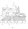
- an agricultural subsoiler indicated as a whole by 1, comprises in its essential parts a frame 2 on which are mounted a plurality of anchor members 3, elongate in shape and tapered at the end part 3a, and on which are fixed a sod-breaker 4, two helical hoes 5 and a reversible tool 6.
- the free end portion 3a of the anchor member 3 is provided with two surfaces 3b, 3c, respectively front and back, and with two lateral surfaces 3d, 3e.
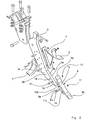
- the tool 6 is shown in detail, together with the means which enable it to be fixed to the anchor member 3, in Figures 2 , 3 and 4 .
- a plate-like body 7 elongate in a prevalent longitudinal direction, having opposed surfaces 7a, 7b, respectively front and back, both substantially rectangular in plan.
- a respective chisel 8a, 8b is defined.
- the tool 6 comprises the fixing means described hereinafter for fixing the plate-like body 7 onto the end part 3a of the anchor member 3 so as to present one or the other of the chisels 8a, 8b in the working position.
- the fixing means comprise two plates 9a, 9b, parallel to each other and welded on the plate-like body 7 on that side where the back surface 7b is located and in a substantially middle position.
- the distance between the plates 9a, 9b is such as to define between them a seat for receiving the end part 3a of the corresponding anchor member 3.
- respective slot-like apertures 10a, 10b and 11a, 11b are provided, having respective major axes 12a, 12b and 13a, 13b converging towards the back surface 7b.
- the fixing means further include a quick-release pin 14 with the corresponding split pin 15 and a bolt 16a comprising screw 16 and nut 17. Two pins or two bolts may similarly be used.
- a cylindrical hole 18 passing between the surfaces 3d, 3e in a position such that when it is aligned with the pair of apertures 10a, 10b, preferably with the part of these latter more distant from the back surface 7b, the corresponding part more distant from the same surface, of the pair of holes 11a, 11b, is aligned with the tangent to the back of the anchor member 3, in its geometrically corresponding part.
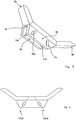
- the coupling between the end part 3a of the anchor member 3 and the tool 6 may be effected in two positions which result in the presentation in the working state of one or the other of the two chisels 8a, 8b, permitting the reversibility of the tool.
- the first position is obtained by placing the back surface 7b of the plate-like body 7 against the front surface 3b of the anchor member 3, so that the inner surfaces of the plates 9a, 9b are alongside, on opposite sides, the lateral surfaces of the end part 3a of the anchor member 3.
- the pin 14 By aligning the apertures 10a, 10b and the hole 18, the pin 14 is positioned as indicated and locked with the split pin 15.
- the screw 16 is likewise positioned in the apertures 11a, 11b and locked in position with the nut 17.
- the reversible tool In order to rotate the reversible tool through 180° with respect to the position described in the previous paragraph, it is first removed from the anchor member, placing the back surface 7b against the front surface 3b, so that the inner surfaces of the plates 9a, 9b are alongside, on opposite sides, the lateral surfaces of the end part 3a of the anchor member 3.
- the pin 14 By aligning the apertures 11a, 11b and the hole 18, inserting the pin 14 therein, locking the pin on the opposite side with the split pin 15, inserting the screw 16 into the holes 10a, 10b and locking it on the opposite side with the nut 17, the locking of the tool on the anchor member is achieved.
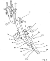
- the fixing means for fixing the plate-like body 7 to the end part 3a of the anchor member 3 comprise the pairs of coaxial cylindrical holes 110a, 110b and 111a, 111b provided, respectively, on the plates 9a, 9b.
- the fixing means further include a bolt comprising a screw 114 and nut 115 and a pin 116, of the peg type, rigidly secured to the tool 6 by means of welding of its opposed longitudinal ends to the plates 9a, 9b.
- the position of the peg 116 is equidistant from the pairs of holes 110a, 110b and 111a, 111b and close to the opposite edge of the plates 9a, 9b from the back surface 7b of the plate-like body 7.
- a quick-release retaining pin may be used.
- the pin 116 is constituted by the shank of a bolt engaged in two corresponding holes of the plates 9a, 9b.
- two coaxial protuberances 116b, 116c are provided, placed respectively on the plates 9a, 9b and extending longitudinally towards each other, in the receiving seat contained between the plates 9a, 9b.
- the pin 116 can be aligned with the tangent to the back surface 3c of the anchor member 3, in its geometrically corresponding part.
- the coupling between the end portion 3a of the anchor member 3 and the tool 6 may be effected in two positions which result in the presentation in the working state of one or the other of the two chisels 8a, 8b, permitting the reversibility of the tool.
- the first position is obtained by placing the back surface 7b of the plate-like body 7 against the front surface 3b of the anchor member 3, in such a way that the inner surfaces of the plates 9a, 9b are alongside, on opposite sides, the lateral surfaces of the end portion 3a of the anchor member 3.
- the screw 114 is positioned as indicated and locked with the nut 115.
- the reversible tool In order to rotate the reversible tool through 180° with respect to the position described in the previous paragraph, it is first removed from the anchor member, placing the back surface 7b against the front surface 3b, in such a way that the inner surfaces of the plates 9a, 9b are alongside, on opposite sides, the lateral surfaces of the end portion 3a of the anchor member 3.
- the holes 111a, 111b and 118 By aligning the holes 111a, 111b and 118, inserting the screw 114 therein and locking the screw on the opposite side with the nut 115, the locking of the tool on the anchor member is achieved.
- the invention makes it possible to position the coupling means between anchor member 3 and tool 6 on protected surfaces in such a way as to prevent wear on them and facilitate their installation and removal.
- the reversible tool of the present invention thus achieves the aims proposed, offering, with respect to the prior art, greater speed in the reversal and exchange operations.
Landscapes
- Life Sciences & Earth Sciences (AREA)
- Engineering & Computer Science (AREA)
- Mechanical Engineering (AREA)
- Soil Sciences (AREA)
- Environmental Sciences (AREA)
- Soil Working Implements (AREA)
- Table Equipment (AREA)
Claims (10)
- Wendewerkzeug (6) für landwirtschaftliche Untergrundpflüge und dergleichen, das einen verlängerten plattenähnlichen Körper (7) an gegenüberliegenden Enden, an denen jeweilige Grubber (8a, 8b) definiert sind, und ein Fixiermittel für das Werkzeug (6) zum Fixieren des Körpers (7) am freien Ende (3a) eines Ankerelements (3) eines Untergrundpfluges (1) umfasst, um in der Arbeitsposition den einen oder den anderen der Grubber (8a, 8b) aufzuweisen, wobei das Fixiermittel Schnellanschlüsse aufweist, wobei das Fixiermittel ein Paar von parallelen und beabstandeten Platten (9a, 9b) aufweist, zwischen denen ein Sitz zur Verbindung mit dem Ankerelement (3) definiert ist, wobei die Platten (9a, 9b) auf derselben Seite des Körpers (7) zwischen den Grubbern (8a, 8b) fixiert sind, dadurch gekennzeichnet, dass die Platten (9a, 9b) mit zumindest zwei Paaren von koaxialen Öffnungen (10a, 10b, 11a, 11 b) versehen sind, wobei zumindest eines von den Paaren vorgesehen ist, um einen jeweiligen Stift (14) oder Bolzen (16a) des Schnellverschlusstyps aufzunehmen.
- Werkzeug gemäß Anspruch 1, wobei die Platten mit zwei Paaren von koaxialen Öffnungen (10a, 10b, 11a, 11 b) versehen sind, wobei jedes Paar vorgesehen ist, einen jeweiligen Stift (14) oder Bolzen (16a) des Schnellverschlusstyps aufzunehmen.
- Werkzeug gemäß Anspruch 2, wobei die Öffnungen auf jeder Platte spiegelsymmetrisch und schlitzähnlich mit Hauptachsen, die in der Nähe des plattenähnlichen Körpers zusammenlaufen, angeordnet sind.
- Werkzeug gemäß Anspruch 2 oder 3, wobei die Öffnungen (10a, 10b, 11a, 11 b) bezüglich des Ankerelements angeordnet sind, so dass in beiden reversiblen Positionen des Werkzeugs ein Paar der Öffnungen mit einer Durchgangsöffnung (18, 118) im Ankerelement (3) und ein anderes Paar der Öffnungen mit einer Tangente zu einem hinteren Teil (3c) des Ankerelements ausgerichtet ist.
- Werkzeug gemäß Anspruch 1, wobei die Öffnungen Durchgangsöffnungen (110a, 110b, 111 a, 111 b) in jeweiligen Positionen sind, so dass, wenn das Werkzeug (6) auf dem Ankerelement (3) in einer von den beiden Betriebspositionen befestigt ist, die jeweiligen Öffnungen in den beiden Platten mit derselben Öffnung (18, 118) des Endbereichs (3a) des Ankerelements koaxial sind, um einen Haltestift oder eine Verbindung vom Schraube (114) - Mutter (115) - Typ darin aufzunehmen.
- Werkzeug gemäß Anspruch 1, wobei zumindest auf einer der Platten (9a, 9b) Anordnungsmittel vorgesehen sind, die sich in den Sitz zum Anordnen einer Rückfläche (3c) des Ankerelements (3) erstreckt, wenn das Werkzeug (6) in der einen oder der anderen der Betriebspositionen befestigt ist.
- Werkzeug gemäß Anspruch 6, wobei das Anordnungsmittel zwei Vorsprünge (116b, 116c) aufweist, die von den jeweiligen Platten (9a, 9b) im Sitz aufragen.
- Werkzeug gemäß Anspruch 7, wobei die Vorsprünge (116b, 116c) koaxial sind.
- Werkzeug gemäß Anspruch 7, wobei das Anordnungsmittel einen Stift (116) aufweist, der sich von der einen zu der anderen der Platten erstreckt.
- Werkzeug gemäß Anspruch 9, wobei der Stift (116) ein Zapfen oder Schraube-Mutter-Typ ist.
Applications Claiming Priority (3)
| Application Number | Priority Date | Filing Date | Title |
|---|---|---|---|
| ITPD20060111 ITPD20060111A1 (it) | 2006-03-30 | 2006-03-30 | Utensile reversibile per ripuntatori agricoli e simili |
| ITPD20060285 ITPD20060285A1 (it) | 2006-07-12 | 2006-07-12 | Utensile reversibile per ripuntatori agricoli e simili |
| PCT/EP2007/002788 WO2007112923A1 (en) | 2006-03-30 | 2007-03-29 | Reversible tool for agricultural subsoilers and the like |
Publications (2)
| Publication Number | Publication Date |
|---|---|
| EP1998604A2 EP1998604A2 (de) | 2008-12-10 |
| EP1998604B1 true EP1998604B1 (de) | 2012-05-02 |
Family
ID=38219472
Family Applications (1)
| Application Number | Title | Priority Date | Filing Date |
|---|---|---|---|
| EP07723732A Active EP1998604B1 (de) | 2006-03-30 | 2007-03-29 | Wendewerkzeug für landwirtschaftliche untergrundpflüge und dergleichen |
Country Status (4)
| Country | Link |
|---|---|
| EP (1) | EP1998604B1 (de) |
| AT (1) | ATE555647T1 (de) |
| EA (1) | EA013674B1 (de) |
| WO (1) | WO2007112923A1 (de) |
Families Citing this family (4)
| Publication number | Priority date | Publication date | Assignee | Title |
|---|---|---|---|---|
| NO336855B1 (no) | 2014-03-12 | 2015-11-16 | Kverneland Group Operations Norway As | Låseanordning for slitedel |
| ITUB20160519A1 (it) * | 2016-01-19 | 2017-07-19 | Aio Srl | Utensile reversibile per macchine ripuntatrici |
| RU2612809C1 (ru) * | 2016-03-24 | 2017-03-13 | федеральное государственное бюджетное образовательное учреждение высшего образования "Волгоградский государственный аграрный университет" (ФГБОУ ВО Волгоградский ГАУ) | Рабочий орган для обработки почвы |
| RU207679U1 (ru) * | 2021-06-07 | 2021-11-11 | Общество с ограниченной ответственностью "Техника-Агро" (ООО "Техника-Агро") | Глубокорыхлитель навесной |
Family Cites Families (7)
| Publication number | Priority date | Publication date | Assignee | Title |
|---|---|---|---|---|
| US1345209A (en) * | 1920-01-09 | 1920-06-29 | Charles A Martin | Cultivator-tooth |
| US1365276A (en) * | 1920-05-19 | 1921-01-11 | Albert S Rue | Attachment for harrows and cultivators |
| DE1151401B (de) * | 1954-11-10 | 1963-07-11 | Koeckerling Geb | Grubberegge |
| DE1100361B (de) * | 1959-02-14 | 1961-02-23 | Koeckerling Geb | Befestigungsschaft fuer die Schare von Grubbereggen |
| DE3133138C2 (de) * | 1981-08-21 | 1984-02-09 | Rabewerk Heinrich Clausing, 4515 Bad Essen | Grubberschar |
| FR2662044B1 (fr) * | 1990-05-18 | 1992-08-28 | Maneville Andre | Dispositif pour la fixation rapide du soc sur la dent flexible ou rigide de cultivateur. |
| CA2256074C (en) * | 1998-12-14 | 2002-12-10 | George N. Loch | Slip on shovel |
-
2007
- 2007-03-29 EA EA200870387A patent/EA013674B1/ru not_active IP Right Cessation
- 2007-03-29 AT AT07723732T patent/ATE555647T1/de active
- 2007-03-29 EP EP07723732A patent/EP1998604B1/de active Active
- 2007-03-29 WO PCT/EP2007/002788 patent/WO2007112923A1/en not_active Ceased
Also Published As
| Publication number | Publication date |
|---|---|
| EA200870387A1 (ru) | 2009-04-28 |
| ATE555647T1 (de) | 2012-05-15 |
| EA013674B1 (ru) | 2010-06-30 |
| EP1998604A2 (de) | 2008-12-10 |
| WO2007112923A1 (en) | 2007-10-11 |
Similar Documents
| Publication | Publication Date | Title |
|---|---|---|
| US9212554B2 (en) | Interchangeable holder system for a chisel | |
| CA2348437C (en) | Hammerless mechanically attached adapter system | |
| EP1407649B1 (de) | Aufsteckanordnung für ein Bodenbearbeitungswerkzeug | |
| EP1998604B1 (de) | Wendewerkzeug für landwirtschaftliche untergrundpflüge und dergleichen | |
| DE602004008375T2 (de) | Fräswerkzeug zur Herstellung von Schlitzen, das ein schnelles Wechseln des Schneidekopfes zulässt. | |
| CA2513869C (en) | Attachment means for drilling equipment | |
| HK1006324B (en) | Cutting element for a coal cutting machine | |
| CA2164831A1 (en) | Spool and wedge assembly and method of use thereof | |
| US6839990B2 (en) | Excavator teeth | |
| EP2672021B1 (de) | Backenbaugruppe für ein abbruchwerkzeug | |
| HK1006324A1 (en) | Cutting element for a coal cutting machine | |
| CA1073004A (en) | Bucket adapter with load absorbing means | |
| EP2801669B1 (de) | Backenbaugruppe für ein Abbruchwerkzeug | |
| US5007484A (en) | Method and apparatus for changing cultivator plow blades | |
| JP2015521697A (ja) | 解体及び建設の機器のための結合先端部材 | |
| CA2505120A1 (en) | Single jaw set multiple tool attachment system | |
| EP2944728B1 (de) | Backenbaugruppe für ein abbruchwerkzeug | |
| CN101420843B (zh) | 用于农用深耕犁之类的可反向工具 | |
| US11161179B2 (en) | Cutting tool assembly | |
| GB2264619A (en) | Mounting tools to prevent overload | |
| RU2394414C2 (ru) | Соединительное устройство для сельскохозяйственной машины | |
| US6095255A (en) | Cultivator component part clamping assembly | |
| EP4186342B1 (de) | Pflugschare | |
| EP1082889A1 (de) | Schnellkuppelsystem für Sägeblätter einer Kreissäge | |
| KR200382974Y1 (ko) | 볼트용 풀림방지구 |
Legal Events
| Date | Code | Title | Description |
|---|---|---|---|
| PUAI | Public reference made under article 153(3) epc to a published international application that has entered the european phase |
Free format text: ORIGINAL CODE: 0009012 |
|
| 17P | Request for examination filed |
Effective date: 20080807 |
|
| AK | Designated contracting states |
Kind code of ref document: A2 Designated state(s): AT BE BG CH CY CZ DE DK EE ES FI FR GB GR HU IE IS IT LI LT LU LV MC MT NL PL PT RO SE SI SK TR |
|
| PUAB | Information related to the publication of an a document modified or deleted |
Free format text: ORIGINAL CODE: 0009199EPPU |
|
| 17Q | First examination report despatched |
Effective date: 20110105 |
|
| GRAP | Despatch of communication of intention to grant a patent |
Free format text: ORIGINAL CODE: EPIDOSNIGR1 |
|
| DAX | Request for extension of the european patent (deleted) | ||
| GRAS | Grant fee paid |
Free format text: ORIGINAL CODE: EPIDOSNIGR3 |
|
| GRAA | (expected) grant |
Free format text: ORIGINAL CODE: 0009210 |
|
| AK | Designated contracting states |
Kind code of ref document: B1 Designated state(s): AT BE BG CH CY CZ DE DK EE ES FI FR GB GR HU IE IS IT LI LT LU LV MC MT NL PL PT RO SE SI SK TR |
|
| REG | Reference to a national code |
Ref country code: GB Ref legal event code: FG4D |
|
| REG | Reference to a national code |
Ref country code: CH Ref legal event code: EP Ref country code: AT Ref legal event code: REF Ref document number: 555647 Country of ref document: AT Kind code of ref document: T Effective date: 20120515 |
|
| REG | Reference to a national code |
Ref country code: IE Ref legal event code: FG4D |
|
| REG | Reference to a national code |
Ref country code: DE Ref legal event code: R096 Ref document number: 602007022424 Country of ref document: DE Effective date: 20120628 |
|
| REG | Reference to a national code |
Ref country code: RO Ref legal event code: EPE |
|
| REG | Reference to a national code |
Ref country code: NL Ref legal event code: VDEP Effective date: 20120502 |
|
| REG | Reference to a national code |
Ref country code: LT Ref legal event code: MG4D Effective date: 20120502 |
|
| PG25 | Lapsed in a contracting state [announced via postgrant information from national office to epo] |
Ref country code: PL Free format text: LAPSE BECAUSE OF FAILURE TO SUBMIT A TRANSLATION OF THE DESCRIPTION OR TO PAY THE FEE WITHIN THE PRESCRIBED TIME-LIMIT Effective date: 20120502 Ref country code: LT Free format text: LAPSE BECAUSE OF FAILURE TO SUBMIT A TRANSLATION OF THE DESCRIPTION OR TO PAY THE FEE WITHIN THE PRESCRIBED TIME-LIMIT Effective date: 20120502 Ref country code: CY Free format text: LAPSE BECAUSE OF FAILURE TO SUBMIT A TRANSLATION OF THE DESCRIPTION OR TO PAY THE FEE WITHIN THE PRESCRIBED TIME-LIMIT Effective date: 20120502 Ref country code: FI Free format text: LAPSE BECAUSE OF FAILURE TO SUBMIT A TRANSLATION OF THE DESCRIPTION OR TO PAY THE FEE WITHIN THE PRESCRIBED TIME-LIMIT Effective date: 20120502 Ref country code: IS Free format text: LAPSE BECAUSE OF FAILURE TO SUBMIT A TRANSLATION OF THE DESCRIPTION OR TO PAY THE FEE WITHIN THE PRESCRIBED TIME-LIMIT Effective date: 20120902 Ref country code: SE Free format text: LAPSE BECAUSE OF FAILURE TO SUBMIT A TRANSLATION OF THE DESCRIPTION OR TO PAY THE FEE WITHIN THE PRESCRIBED TIME-LIMIT Effective date: 20120502 |
|
| REG | Reference to a national code |
Ref country code: AT Ref legal event code: MK05 Ref document number: 555647 Country of ref document: AT Kind code of ref document: T Effective date: 20120502 |
|
| PG25 | Lapsed in a contracting state [announced via postgrant information from national office to epo] |
Ref country code: LV Free format text: LAPSE BECAUSE OF FAILURE TO SUBMIT A TRANSLATION OF THE DESCRIPTION OR TO PAY THE FEE WITHIN THE PRESCRIBED TIME-LIMIT Effective date: 20120502 Ref country code: PT Free format text: LAPSE BECAUSE OF FAILURE TO SUBMIT A TRANSLATION OF THE DESCRIPTION OR TO PAY THE FEE WITHIN THE PRESCRIBED TIME-LIMIT Effective date: 20120903 Ref country code: GR Free format text: LAPSE BECAUSE OF FAILURE TO SUBMIT A TRANSLATION OF THE DESCRIPTION OR TO PAY THE FEE WITHIN THE PRESCRIBED TIME-LIMIT Effective date: 20120803 Ref country code: SI Free format text: LAPSE BECAUSE OF FAILURE TO SUBMIT A TRANSLATION OF THE DESCRIPTION OR TO PAY THE FEE WITHIN THE PRESCRIBED TIME-LIMIT Effective date: 20120502 |
|
| PG25 | Lapsed in a contracting state [announced via postgrant information from national office to epo] |
Ref country code: BE Free format text: LAPSE BECAUSE OF FAILURE TO SUBMIT A TRANSLATION OF THE DESCRIPTION OR TO PAY THE FEE WITHIN THE PRESCRIBED TIME-LIMIT Effective date: 20120502 |
|
| PG25 | Lapsed in a contracting state [announced via postgrant information from national office to epo] |
Ref country code: EE Free format text: LAPSE BECAUSE OF FAILURE TO SUBMIT A TRANSLATION OF THE DESCRIPTION OR TO PAY THE FEE WITHIN THE PRESCRIBED TIME-LIMIT Effective date: 20120502 Ref country code: DK Free format text: LAPSE BECAUSE OF FAILURE TO SUBMIT A TRANSLATION OF THE DESCRIPTION OR TO PAY THE FEE WITHIN THE PRESCRIBED TIME-LIMIT Effective date: 20120502 Ref country code: AT Free format text: LAPSE BECAUSE OF FAILURE TO SUBMIT A TRANSLATION OF THE DESCRIPTION OR TO PAY THE FEE WITHIN THE PRESCRIBED TIME-LIMIT Effective date: 20120502 Ref country code: SK Free format text: LAPSE BECAUSE OF FAILURE TO SUBMIT A TRANSLATION OF THE DESCRIPTION OR TO PAY THE FEE WITHIN THE PRESCRIBED TIME-LIMIT Effective date: 20120502 Ref country code: NL Free format text: LAPSE BECAUSE OF FAILURE TO SUBMIT A TRANSLATION OF THE DESCRIPTION OR TO PAY THE FEE WITHIN THE PRESCRIBED TIME-LIMIT Effective date: 20120502 |
|
| PLBE | No opposition filed within time limit |
Free format text: ORIGINAL CODE: 0009261 |
|
| STAA | Information on the status of an ep patent application or granted ep patent |
Free format text: STATUS: NO OPPOSITION FILED WITHIN TIME LIMIT |
|
| 26N | No opposition filed |
Effective date: 20130205 |
|
| PG25 | Lapsed in a contracting state [announced via postgrant information from national office to epo] |
Ref country code: ES Free format text: LAPSE BECAUSE OF FAILURE TO SUBMIT A TRANSLATION OF THE DESCRIPTION OR TO PAY THE FEE WITHIN THE PRESCRIBED TIME-LIMIT Effective date: 20120813 |
|
| REG | Reference to a national code |
Ref country code: DE Ref legal event code: R097 Ref document number: 602007022424 Country of ref document: DE Effective date: 20130205 |
|
| PG25 | Lapsed in a contracting state [announced via postgrant information from national office to epo] |
Ref country code: MC Free format text: LAPSE BECAUSE OF NON-PAYMENT OF DUE FEES Effective date: 20130331 |
|
| REG | Reference to a national code |
Ref country code: CH Ref legal event code: PL |
|
| GBPC | Gb: european patent ceased through non-payment of renewal fee |
Effective date: 20130329 |
|
| REG | Reference to a national code |
Ref country code: IE Ref legal event code: MM4A |
|
| PG25 | Lapsed in a contracting state [announced via postgrant information from national office to epo] |
Ref country code: IE Free format text: LAPSE BECAUSE OF NON-PAYMENT OF DUE FEES Effective date: 20130329 Ref country code: CH Free format text: LAPSE BECAUSE OF NON-PAYMENT OF DUE FEES Effective date: 20130331 Ref country code: LI Free format text: LAPSE BECAUSE OF NON-PAYMENT OF DUE FEES Effective date: 20130331 Ref country code: GB Free format text: LAPSE BECAUSE OF NON-PAYMENT OF DUE FEES Effective date: 20130329 |
|
| PG25 | Lapsed in a contracting state [announced via postgrant information from national office to epo] |
Ref country code: MT Free format text: LAPSE BECAUSE OF FAILURE TO SUBMIT A TRANSLATION OF THE DESCRIPTION OR TO PAY THE FEE WITHIN THE PRESCRIBED TIME-LIMIT Effective date: 20120502 |
|
| PG25 | Lapsed in a contracting state [announced via postgrant information from national office to epo] |
Ref country code: LU Free format text: LAPSE BECAUSE OF NON-PAYMENT OF DUE FEES Effective date: 20130329 Ref country code: HU Free format text: LAPSE BECAUSE OF FAILURE TO SUBMIT A TRANSLATION OF THE DESCRIPTION OR TO PAY THE FEE WITHIN THE PRESCRIBED TIME-LIMIT; INVALID AB INITIO Effective date: 20070329 |
|
| REG | Reference to a national code |
Ref country code: FR Ref legal event code: PLFP Year of fee payment: 10 |
|
| REG | Reference to a national code |
Ref country code: FR Ref legal event code: PLFP Year of fee payment: 11 |
|
| REG | Reference to a national code |
Ref country code: FR Ref legal event code: PLFP Year of fee payment: 12 |
|
| P01 | Opt-out of the competence of the unified patent court (upc) registered |
Effective date: 20230530 |
|
| P04 | Withdrawal of opt-out of the competence of the unified patent court (upc) registered |
Free format text: CASE NUMBER: APP_42713/2024 Effective date: 20240719 |
|
| PGFP | Annual fee paid to national office [announced via postgrant information from national office to epo] |
Ref country code: BG Payment date: 20250321 Year of fee payment: 19 |
|
| PGFP | Annual fee paid to national office [announced via postgrant information from national office to epo] |
Ref country code: CZ Payment date: 20250325 Year of fee payment: 19 |
|
| PGFP | Annual fee paid to national office [announced via postgrant information from national office to epo] |
Ref country code: DE Payment date: 20260319 Year of fee payment: 20 |
|
| PGFP | Annual fee paid to national office [announced via postgrant information from national office to epo] |
Ref country code: RO Payment date: 20260323 Year of fee payment: 20 Ref country code: IT Payment date: 20260304 Year of fee payment: 20 |
|
| PGFP | Annual fee paid to national office [announced via postgrant information from national office to epo] |
Ref country code: FR Payment date: 20260320 Year of fee payment: 20 |
|
| PGFP | Annual fee paid to national office [announced via postgrant information from national office to epo] |
Ref country code: TR Payment date: 20260325 Year of fee payment: 20 |