EP1998441A2 - Automatische Kontrolle der Verstärkung infolge der Wahrscheinlichkeitsdichte der empfangenen Leistung - Google Patents
Automatische Kontrolle der Verstärkung infolge der Wahrscheinlichkeitsdichte der empfangenen Leistung Download PDFInfo
- Publication number
- EP1998441A2 EP1998441A2 EP08156843A EP08156843A EP1998441A2 EP 1998441 A2 EP1998441 A2 EP 1998441A2 EP 08156843 A EP08156843 A EP 08156843A EP 08156843 A EP08156843 A EP 08156843A EP 1998441 A2 EP1998441 A2 EP 1998441A2
- Authority
- EP
- European Patent Office
- Prior art keywords
- module
- noise
- signal
- histogram
- receiver
- Prior art date
- Legal status (The legal status is an assumption and is not a legal conclusion. Google has not performed a legal analysis and makes no representation as to the accuracy of the status listed.)
- Withdrawn
Links
Images


Classifications
-
- H—ELECTRICITY
- H03—ELECTRONIC CIRCUITRY
- H03G—CONTROL OF AMPLIFICATION
- H03G3/00—Gain control in amplifiers or frequency changers
- H03G3/20—Automatic control
- H03G3/30—Automatic control in amplifiers having semiconductor devices
- H03G3/3052—Automatic control in amplifiers having semiconductor devices in bandpass amplifiers (H.F. or I.F.) or in frequency-changers used in a (super)heterodyne receiver
- H03G3/3078—Circuits generating control signals for digitally modulated signals
Definitions
- the present invention is applicable to radio frequency receivers to receive weak signals in a pulsed interference environment. This is notably the case for positioning receivers that use the signals received from GNSS (Global Navigation Satellite Systems) satellite constellations such as GPS (Gobal Positioning System) and Enhanced GPS, GLONASS (Global Orbiting Navigation Satellite System) systems and, in the near future, Galileo.
- GNSS Global Navigation Satellite Systems
- GPS Gobal Positioning System
- GLONASS Global Orbiting Navigation Satellite System
- Galileo Galileo
- the received signal is typically about ten dB below the thermal noise of the receiver.
- the signal processing must allow the recovery of one or more carriers and one or more modulation codes of said carriers which include characteristic information of the satellite transmitting said carriers.
- the central part of the digital processing is a correlation of the received signals with local replicas of said signals.
- Ground beacons transmit signals in response to the interrogation signals transmitted by the aircraft. These ground beacons and on-board interrogators emit high instantaneous power signals (of the order of ten kilowatts) in the frequency bands used for the positioning signals (around 1200 MHz).
- a known solution to this problem is in particular the so-called "blanking" technique which consists in locating the interfering signal and in suppressing subsequent processing the received signal disturbed by it.
- This solution is ineffective when the interference density increases to the point of almost permanently covering the useful signal.
- the blanking leads to eliminating any useful signal at the same time as the interfering signal.
- This type of scenario is likely to occur in a large part of European airspace, particularly at an altitude of about 40,000 feet where the number of DME beacons seen by an aircraft can be of the order of 60 at times of maximum traffic density.
- the present invention proposes a device for receiving a radio frequency signal comprising a module for estimating a characteristic quantity of said signal chosen from the amplitude, power group, a module for automatic control of the gain of the receiver, and a module for analyzing the probability density function of said characteristic quantity whose parameters are adjustable to provide inputs to the automatic gain control module which ensure a substantially optimal gain of the receiver, characterized in that the analysis module of the probability density function comprises a sub-module for calculating an averaged histogram of said function and a sub-module for determining the noise by comparison with a statistic chosen a priori.
- the noise determination sub-module performs a decomposition of the histogram in sum of X 2 laws and determines the one that is the most probable representative law of the noise.
- the noise determination sub-module performs a decomposition of the histogram in sum of expected laws for interference and expected laws for noise.
- the noise determination sub-module correlates the signal histogram with a noise histogram according to an expected law.
- the receiving device further comprises a module for processing interfering signals at the output of the analysis module of the probability density function.
- the interfering signal processing module performs a blanking whose threshold is calculated by reference to the noise estimated by the analysis module of the probability density function.
- the interfering signal processing module carries out several blanking in frequency sub-bands of the signal, each blanking threshold being calculated by reference to the noise estimated by the analysis module of the probability density function.
- the interfering signal processing module performs an inversion of a characteristic quantity of the signal chosen in the amplitude, power group from the output of the estimation module.
- the invention also discloses a method of processing a radio frequency signal comprising a step of estimating a characteristic quantity of said selected signal in the amplitude, power group and a step of automatic control of the gain of the receiver and a step of analysis the probability density function of said characteristic quantity whose parameters are adjustable to provide inputs to the automatic gain control step to ensure a substantially optimal gain of the receiver characterized in that the function analysis step probability density comprises a sub-module for calculating an averaged histogram of said function and a sub-module for determining the noise by comparison with a statistic chosen a priori.
- the invention also has the advantage of allowing a reduction in the dynamics of the signal processing operators due to the adaptation of the resulting gain.
- the GPS and future GPS frequencies are per band: E6 (1260-1300 MHz), L2 (1216-1240 MHz) and L5 / E5a (1164-1188 MHz).
- the Galileo frequencies are: E6, E5a and E5b (1188-1215 MHz).
- the DME transmission frequencies are 1025-1150 MHz for an on-board interrogator and the ground beacons transmit in the band 962-1213 MHz. (so in the bands E5a and E5b of GALILEO and L5 of GPS).
- the total band is divided into 126 channels and transmitting and receiving a beacon are shifted 63 MHz. The channels are therefore spaced 1 MHz apart.
- the ground beacons respond to them with a fixed delay of 50 microseconds and the receiver of the on-board interrogator then searches for the response pulse pairs that have the correct spacing between them.
- the signal strength emitted by the ground beacons is order
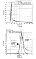
- the figure 2 shows the number and power of DME beacons in the allocated frequency bands that are very close to L5 / E5a at the point of maximum density in the northern European airspace called "hotspot".
- the airplane gain is for illustration set at -10dBi in this figure.
- the figure also shows: an example of the input thermal noise level (# -125dBW), the blanking threshold resulting from the biased estimate of thermal noise (# - 115 dBW) and the optimal blanking threshold ( # - 122 dBW).
- the difference of 7 dB is very significant compared to the required performances of the receivers.
- a GNSS signal is below the thermal noise.
- a minimum signal-to-noise ratio is required for signal processing, based on most of the information on correlations, if any helped, of the elements received and their local replicas, can be effective.
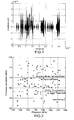
- the useful signal at the correlators will be extremely degraded. This impossibility of reaching the useful signal is clearly illustrated on the figure 5 which shows the power curves at the filter output with and without DME interference.
- the time horizon is about 2 ⁇ s. Similar situations can occur in the presence of radars or very wideband (UWB) pulsed devices
- GNSS receivers use pre-correlation processing to handle pulsed interference, for example, the "blanking” method or the "FDAF” method.
- Blanking is a simple process of cutting the signal during interference.
- the method can not work when the interference is too dense because the useful signal is completely lost.
- the FDAF method is an improvement of this process. It consists in cutting the reception band into sub-bands and applying the blanking method to each sub-band.
- pulsed interference is detected relative to the estimate of thermal noise. Since the thermal noise estimate is higher than the thermal noise itself when weak pulses occur and are not detected, the blanking threshold is therefore higher than it should be as illustrated on the figure 2 .
- pulsed interference enters into the calculation of the AGC.
- the CAG responds by going down the VGA gain. So even more pulsed interference goes into the estimation of thermal noise and so on. This continues to diverge until the receiver accepts the majority of pulsed interference and no longer codes the useful signal.
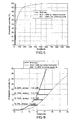
- the idea of the invention is to improve the estimation of thermal noise and continuous interference in the presence of pulsed interference whatever their powers and their repetition rates. It assumes that low-amplitude filtered samples are insensitive to pulsed interference and that the thermal noise energy characteristic is quasi-Gaussian, as shown by figure 4 .
- the purpose of the AGC is to seek to detect the left side of the histogram as represented on the figure 4 then extrapolate the command for the VGA.
- the figure 5 represents the same data in cumulative probability. In these figures we have chosen to represent the power probability function. The analysis of the probability function of the amplitude of the received signal could be used in a completely substitutable manner and would give equivalent results.
- a zoom is performed on the first part of the curve ( figure 6 ).
- the curves are similar but are not exactly identical.
- This device makes it possible to maintain the tracking in code and in carrier of a GNSS receiver for the air navigation on the frequencies E5a / E5b / L5, especially on European and American hot-spots (pulsed interference). It works in the presence of continuous interference. It is not sensitive to the temperature change of the electronics. It also makes it possible to deal with radar-type pulsed interference such as UWB.
- radar-type pulsed interference such as UWB.
- the realization in FPGA is of low cost.
- the AGC is robust regardless of the pulsed interference scenario.
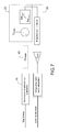
- FIG. 8 illustrates the means used to directly determine the histogram of the power probability function.
- the signal is broken down into elementary sums to identify Gaussian noise.
- This solution requires the exact knowledge of the pulses (form, probability).
- This solution is not very applicable to on-board receivers but can be interesting for fixed receivers, whose environment is perfectly determined (constellation control station).
- FIG. 11 illustrates one of the variants of this embodiment in which the histogram is decomposed into a noise component according to a prior distribution and a component carrying the other elements of the signal.
- the interference is easily isolated.
- the simple blanking is then performed by deleting the signal in the time range where the interference is present.
- Those skilled in the art can perform the necessary device to perform this deletion.
- To carry out a blanking by subband of the frequency domain it is possible, for example, to provide a subband detection filter. If there is no prior knowledge of the characteristics of the interfering signals, standard bandpass filters will be used. If, on the other hand, we know the characteristics of the interfering signals (frequency and shape of the pulses), we will be able to use FIRs. Rejectors filters then allow the signal to be cut off on the tracks where the interfering signals are present.
- a reduced bias noise is estimated in each of the frequency subbands and this noise serves as a reference for the suppression of the received signal in each of the subbands.
- a third mode of interference processing is to invert the amplitude or power of the received signal, amplitude interference / high power being then clipped.
- the inversion of amplitude or power consists of multiplying the input signal by the inverse of the amplitude or filtered power estimate. In the case where the inversion relates to the power of the signal, the power of the output signal is equal to the inverse of the power of the input signal, to a constant close.
- the power of the output signal is equal to the inverse of the square of the power of the input signal, to a constant.
- the power reversal is theoretically optimal.
- the amplitude inversion is less sensitive to imperfections of implementation.
- the inversion of power can not completely replace the blanking: when the ADC is saturated by pulsed interference, it is necessary to carry out a blanking in order to limit the parasitic frequencies which otherwise would enter the correlation.
- the setpoint to which is enslaved the product of the source and inverted signals is formed from the noise estimate made by the device of the invention. It is possible to perform a frequency subband inversion. This last treatment is particularly advantageous for the Binary Offset Carrier (BOC) signals for which the reversal will be carried out on four frequency bands (two wide bands and two narrow bands). Other modes of noise treatment are possible at the output of the optimal control of the AGC which allows to estimate the thermal noise with a reduced bias.
- the invention is therefore not limited to the embodiments disclosed in the present description.
Landscapes
- Circuits Of Receivers In General (AREA)
- Position Fixing By Use Of Radio Waves (AREA)
- Noise Elimination (AREA)
Applications Claiming Priority (1)
| Application Number | Priority Date | Filing Date | Title |
|---|---|---|---|
| FR0703735A FR2916589A1 (fr) | 2007-05-25 | 2007-05-25 | Controle automatique de gain asservi sur la densite de probabilite de puissance recue |
Publications (2)
| Publication Number | Publication Date |
|---|---|
| EP1998441A2 true EP1998441A2 (de) | 2008-12-03 |
| EP1998441A3 EP1998441A3 (de) | 2009-03-04 |
Family
ID=38895850
Family Applications (2)
| Application Number | Title | Priority Date | Filing Date |
|---|---|---|---|
| EP08156842A Withdrawn EP1998440A3 (de) | 2007-05-25 | 2008-05-23 | Automatische Kontrolle der Verstärkung infolge der Wahrscheinlichkeitsdichte der empfangenen Leistung |
| EP08156843A Withdrawn EP1998441A3 (de) | 2007-05-25 | 2008-05-23 | Automatische Kontrolle der Verstärkung infolge der Wahrscheinlichkeitsdichte der empfangenen Leistung |
Family Applications Before (1)
| Application Number | Title | Priority Date | Filing Date |
|---|---|---|---|
| EP08156842A Withdrawn EP1998440A3 (de) | 2007-05-25 | 2008-05-23 | Automatische Kontrolle der Verstärkung infolge der Wahrscheinlichkeitsdichte der empfangenen Leistung |
Country Status (4)
| Country | Link |
|---|---|
| US (2) | US20090104883A1 (de) |
| EP (2) | EP1998440A3 (de) |
| CA (2) | CA2632062A1 (de) |
| FR (1) | FR2916589A1 (de) |
Families Citing this family (9)
| Publication number | Priority date | Publication date | Assignee | Title |
|---|---|---|---|---|
| FR2916589A1 (fr) * | 2007-05-25 | 2008-11-28 | Thales Sa | Controle automatique de gain asservi sur la densite de probabilite de puissance recue |
| FR2916538B1 (fr) * | 2007-05-25 | 2010-09-10 | Thales Sa | Traitement des interferences d'un signal radiofrequence par inversion de puissance |
| FR2931600B1 (fr) * | 2008-05-23 | 2012-10-12 | Thales Sa | Systeme et procede de multi-correlation avec filtre adapte a la modulation pour l'acquisition rapide et la poursuite d'un signal de radionavigation en presence de brouillage |
| CN101873152B (zh) * | 2010-07-12 | 2013-08-14 | 西安电子科技大学 | 基于最佳带宽滤波预处理的多普勒频移估计方法 |
| FR2969869B1 (fr) * | 2010-12-23 | 2012-12-28 | Thales Sa | Dispositif de controle automatique de gain pour recepteur de positionnement par satellites |
| US8923452B2 (en) * | 2013-03-18 | 2014-12-30 | Lockheed Martin Corporation | Noise-based gain adjustment and amplitude estimation system |
| FR3075975B1 (fr) * | 2017-12-21 | 2020-05-22 | Thales | Recepteur de signaux, en particulier de signaux gnss, comprenant un filtre de rejection d'interferences, et procede associe |
| US10277184B1 (en) * | 2018-05-18 | 2019-04-30 | Trellisware Technologies, Inc. | Analog automatic gain control based on estimated distributions of signal characteristics |
| US20250093462A1 (en) * | 2023-09-15 | 2025-03-20 | Intelligent Fusion Technology, Inc. | Method, system and storage medium for model predictive automatic gain control of satellite transponder under additive white gaussian noise jamming |
Family Cites Families (15)
| Publication number | Priority date | Publication date | Assignee | Title |
|---|---|---|---|---|
| US5267272A (en) * | 1988-10-24 | 1993-11-30 | Hughes Aircraft Company | Receiver automatic gain control (AGC) |
| IL92021A (en) * | 1988-10-24 | 1994-06-24 | Hughes Aircraft Co | Automatic control amplifier for spring frequency reception |
| US5029182A (en) * | 1988-10-24 | 1991-07-02 | Hughes Aircraft Company | Automatic gain control (AGC) for frequency hopping receiver |
| US5101416A (en) * | 1990-11-28 | 1992-03-31 | Novatel Comunications Ltd. | Multi-channel digital receiver for global positioning system |
| US5390207A (en) * | 1990-11-28 | 1995-02-14 | Novatel Communications Ltd. | Pseudorandom noise ranging receiver which compensates for multipath distortion by dynamically adjusting the time delay spacing between early and late correlators |
| US5881096A (en) * | 1997-06-05 | 1999-03-09 | Itt Manufacturing Enterprises, Inc. | Method for removing bias in a frequency hopping digital communication system |
| US6128353A (en) * | 1997-07-07 | 2000-10-03 | Lucent Technologies, Inc. | Code division multiple access system with dynamic histogram control |
| CN1156994C (zh) * | 1998-07-20 | 2004-07-07 | 三星电子株式会社 | 用于全球定位系统的多信道数字接收机 |
| US6259391B1 (en) * | 1999-06-18 | 2001-07-10 | Nortel Networks Limited | Analog gain control adjustment using a probabilistic algorithm |
| IL158211A0 (en) * | 2001-04-04 | 2004-05-12 | Quellan Inc | Method and system for decoding multilevel signals |
| CA2446301C (en) * | 2001-05-04 | 2009-10-27 | Glowlink Communications Technology | Method and apparatus for monitoring and controlling gain compression in a transmitted signal |
| EP1780915B1 (de) * | 2003-02-21 | 2009-04-15 | Atheros Comunications Inc. | Verfahren und Vorrichtung zur ausgewählten Nichtbeachtung von Gleichkanalübertragungen auf einem Medium |
| US7912158B2 (en) * | 2005-11-08 | 2011-03-22 | Navcom Technology, Inc. | Sampling threshold and gain for satellite navigation receiver |
| FR2916538B1 (fr) * | 2007-05-25 | 2010-09-10 | Thales Sa | Traitement des interferences d'un signal radiofrequence par inversion de puissance |
| FR2916589A1 (fr) * | 2007-05-25 | 2008-11-28 | Thales Sa | Controle automatique de gain asservi sur la densite de probabilite de puissance recue |
-
2007
- 2007-05-25 FR FR0703735A patent/FR2916589A1/fr not_active Withdrawn
-
2008
- 2008-05-21 US US12/124,228 patent/US20090104883A1/en not_active Abandoned
- 2008-05-21 US US12/124,345 patent/US20090004990A1/en not_active Abandoned
- 2008-05-23 EP EP08156842A patent/EP1998440A3/de not_active Withdrawn
- 2008-05-23 EP EP08156843A patent/EP1998441A3/de not_active Withdrawn
- 2008-05-23 CA CA002632062A patent/CA2632062A1/en not_active Abandoned
- 2008-05-23 CA CA002632087A patent/CA2632087A1/en not_active Abandoned
Also Published As
| Publication number | Publication date |
|---|---|
| US20090104883A1 (en) | 2009-04-23 |
| EP1998441A3 (de) | 2009-03-04 |
| CA2632062A1 (en) | 2008-11-25 |
| EP1998440A2 (de) | 2008-12-03 |
| CA2632087A1 (en) | 2008-11-25 |
| EP1998440A3 (de) | 2009-03-04 |
| FR2916589A1 (fr) | 2008-11-28 |
| US20090004990A1 (en) | 2009-01-01 |
Similar Documents
| Publication | Publication Date | Title |
|---|---|---|
| EP1998441A2 (de) | Automatische Kontrolle der Verstärkung infolge der Wahrscheinlichkeitsdichte der empfangenen Leistung | |
| EP2000815A1 (de) | Behandlung von Störungen eines Hochfrequenzsignals mittels invertierte Leistung | |
| EP2637040A1 (de) | Adaptives Schätzungsverfahren des elektronischen Inhalts der Ionosphäre | |
| US10585195B2 (en) | Cepstrum-based multipath mitigation of a spread spectrum radiocommunication signal | |
| FR2729474A1 (fr) | Procede et dispositif pour estimer la distance de detection d'un radar | |
| WO2003058270A1 (fr) | Dispositif et procede de suppression de signaux radioelectriques pulses | |
| EP3709058A1 (de) | Verfahren zur kontrolliereung der integrität eines funknavigations-satellitensignals und empfänger geeignet zur durchführung des verfahrens | |
| EP2469707B1 (de) | Automatische Kontrollvorrichtung der Verstärkung für satellitengesteuerten Positionsempfänger | |
| EP3157181B1 (de) | Ultra wideband signalerkennung | |
| EP2533426B1 (de) | Empfangssystem, das mit einem Mechanismus gegen Pulsinterferenzen ausgestattet ist | |
| FR3008191A1 (fr) | Procede de detection d'au moins une cible par radar doppler a impulsions avec mesure non ambigue de la vitesse radiale et radar doppler a impulsions pour la mise en oeuvre d'un tel procede | |
| WO2003046602A1 (fr) | Procede de detection et de traitement de signaux pulses dans un signal radioelectrique | |
| EP3400457B1 (de) | Verfahren zum löschen eines signals aus einem bordradar | |
| EP1742376B1 (de) | Nachrichtenzusammenmischungsverfahren für Nachrichten, die von Funkempfänger stammen und Funkempfängervorrichtung | |
| FR3009755A1 (fr) | Procede et dispositif de mesure du rapport des puissances interference a bruit dans un recepteur gnss | |
| FR3007146A1 (fr) | Procede d'optimisation d'un recepteur gnss et dispositif d'estimation du rapport interferences a bruit d'un recepteur gnss | |
| FR3140177A1 (fr) | Procédé et dispositif de détection d’obstacles proches par Radar Passif Multistatique GNSS pour plateformes mobiles | |
| FR3166444A1 (fr) | Procédé d’amélioration de la précision de la position d’un porteur mobile | |
| Chandrasekhar et al. | GNSS signal detection under noise uncertainty | |
| Vallés et al. | Phase tracking with a cognitive Antijam Receiver System (CARS) | |
| FR2818470A1 (fr) | Procede de deparasitage, en reception, d'un signal radioelectrique emis en bande etalee | |
| Dafesh et al. | Cognitive antijam receiver system (CARS) for GNSS | |
| FR2916917A1 (fr) | Procede,dispositif et produit programme d'ordinateur pour la selection et le classement de signaux radio recus en fonction de leur qualite |
Legal Events
| Date | Code | Title | Description |
|---|---|---|---|
| PUAI | Public reference made under article 153(3) epc to a published international application that has entered the european phase |
Free format text: ORIGINAL CODE: 0009012 |
|
| AK | Designated contracting states |
Kind code of ref document: A2 Designated state(s): AT BE BG CH CY CZ DE DK EE ES FI FR GB GR HR HU IE IS IT LI LT LU LV MC MT NL NO PL PT RO SE SI SK TR |
|
| AX | Request for extension of the european patent |
Extension state: AL BA MK RS |
|
| RIN1 | Information on inventor provided before grant (corrected) |
Inventor name: KIRBY, ESTELLE Inventor name: RENARD, ALAIN |
|
| PUAL | Search report despatched |
Free format text: ORIGINAL CODE: 0009013 |
|
| AK | Designated contracting states |
Kind code of ref document: A3 Designated state(s): AT BE BG CH CY CZ DE DK EE ES FI FR GB GR HR HU IE IS IT LI LT LU LV MC MT NL NO PL PT RO SE SI SK TR |
|
| AX | Request for extension of the european patent |
Extension state: AL BA MK RS |
|
| 17Q | First examination report despatched |
Effective date: 20091006 |
|
| 17P | Request for examination filed |
Effective date: 20090902 |
|
| AKX | Designation fees paid |
Designated state(s): BE DE FR GB |
|
| GRAP | Despatch of communication of intention to grant a patent |
Free format text: ORIGINAL CODE: EPIDOSNIGR1 |
|
| STAA | Information on the status of an ep patent application or granted ep patent |
Free format text: STATUS: THE APPLICATION IS DEEMED TO BE WITHDRAWN |
|
| 18D | Application deemed to be withdrawn |
Effective date: 20100902 |