EP1998366A1 - Substrate support, substrate processing device and method of placing a substrate - Google Patents
Substrate support, substrate processing device and method of placing a substrate Download PDFInfo
- Publication number
- EP1998366A1 EP1998366A1 EP07107164A EP07107164A EP1998366A1 EP 1998366 A1 EP1998366 A1 EP 1998366A1 EP 07107164 A EP07107164 A EP 07107164A EP 07107164 A EP07107164 A EP 07107164A EP 1998366 A1 EP1998366 A1 EP 1998366A1
- Authority
- EP
- European Patent Office
- Prior art keywords
- substrate
- fastening means
- frame
- edge
- substrate support
- Prior art date
- Legal status (The legal status is an assumption and is not a legal conclusion. Google has not performed a legal analysis and makes no representation as to the accuracy of the status listed.)
- Granted
Links
Images


Classifications
-
- H—ELECTRICITY
- H10—SEMICONDUCTOR DEVICES; ELECTRIC SOLID-STATE DEVICES NOT OTHERWISE PROVIDED FOR
- H10P—GENERIC PROCESSES OR APPARATUS FOR THE MANUFACTURE OR TREATMENT OF DEVICES COVERED BY CLASS H10
- H10P72/00—Handling or holding of wafers, substrates or devices during manufacture or treatment thereof
- H10P72/70—Handling or holding of wafers, substrates or devices during manufacture or treatment thereof for supporting or gripping
- H10P72/76—Handling or holding of wafers, substrates or devices during manufacture or treatment thereof for supporting or gripping using mechanical means, e.g. clamps or pinches
- H10P72/7604—Handling or holding of wafers, substrates or devices during manufacture or treatment thereof for supporting or gripping using mechanical means, e.g. clamps or pinches the wafers being placed on a susceptor, stage or support
-
- H—ELECTRICITY
- H10—SEMICONDUCTOR DEVICES; ELECTRIC SOLID-STATE DEVICES NOT OTHERWISE PROVIDED FOR
- H10P—GENERIC PROCESSES OR APPARATUS FOR THE MANUFACTURE OR TREATMENT OF DEVICES COVERED BY CLASS H10
- H10P72/00—Handling or holding of wafers, substrates or devices during manufacture or treatment thereof
- H10P72/50—Handling or holding of wafers, substrates or devices during manufacture or treatment thereof for positioning, orientation or alignment
-
- Y—GENERAL TAGGING OF NEW TECHNOLOGICAL DEVELOPMENTS; GENERAL TAGGING OF CROSS-SECTIONAL TECHNOLOGIES SPANNING OVER SEVERAL SECTIONS OF THE IPC; TECHNICAL SUBJECTS COVERED BY FORMER USPC CROSS-REFERENCE ART COLLECTIONS [XRACs] AND DIGESTS
- Y10—TECHNICAL SUBJECTS COVERED BY FORMER USPC
- Y10T—TECHNICAL SUBJECTS COVERED BY FORMER US CLASSIFICATION
- Y10T29/00—Metal working
- Y10T29/49—Method of mechanical manufacture
- Y10T29/49998—Work holding
Definitions
- the present invention relates to a substrate support for supporting a substrate to be processed in a vacuum processing chamber, said substrate support comprising: a frame for carrying said substrate; and at least a first fastening means fixedly attached to said frame for aligning said substrate relative to said frame by attaching said substrate to said first fastening means.
- a substrate processing device for processing a substrate comprising: at least one process chamber; processing tools arranged in said process chamber for processing said substrate; and an edge exclusion projecting over a portion of the substrate surface of a substrate supported in a substrate support and received in said process chamber for preventing processing of a portion of said substrate.
- the invention relates to a method of placing a substrate on a substrate support.
- PVD physical vapor deposition
- CVD chemical vapor deposition
- PECVD plasma enhanced chemical vapor deposition
- single layers or multi-layer systems are deposited on glass substrates to produce coated panels, display screens, OLED (organic light emitting diode) panels, thermally insulating glass panels, etc.
- the layer deposition may be provided in static or in dynamic coating processes.
- static coating processes the substrate is positioned on a substrate supporting platform to be coated within a vacuum coating chamber.
- the substrate is secured to a support platform within a deposition chamber by clamp springs or a clamp frame while being coated.
- the substrate holder may include an edge exclusion or shadow frame for preventing processing of a perimeter portion of the (upper) substrate surface.
- a particular shadow frame supported on a shadow frame support within the cavity of a processing chamber is disclosed in US patent No. 6,773,562 B1 . By providing the shadow frame processing gases and plasma are prevented from reaching the edge and the backside of the substrate.
- the substrate is fixedly attached to a carrier in order to provide the transport and transfer of the substrate between the various handling and processing chambers.
- the carrier comprises a frame extending along the edge of the glass substrate.
- the glass substrate is fixed in the carrier by clamp springs.
- particles may also be deposited on the frame causing particle problems.
- the carrier when the carrier is locked in, locked out and transported between various coating chambers, it may be heated up and cooled down at frequent intervals. Due to thermal expansions of the carrier the glass substrate has no defined position relative to the carrier during the processing/ coating steps.
- a number of problems have been identified with respect to the handling and processing of large-size substrates. Particularly, in a static process the transport of glass substrates is difficult and the substrate may be damaged, e. g. by displacement of the substrate arranged on the supporting platform when positioning and aligning the substrate. Furthermore, if the edge exclusion is not properly centred relative to the substrate during the processing steps, the amount of shadowing will be unequal and inexact. Particularly, when depositing a number of layers in different chambers, re-positioning of the substrate may be required after moving the substrate from one processing chamber into the next processing chamber.
- a substrate support for supporting a substrate to be processed in a vacuum processing chamber comprises: a frame for carrying said substrate; and at least a first fastening means fixedly attached to said frame for aligning said substrate relative to said frame by attaching said substrate to said first fastening means.
- the substrate support further comprises at least a second fastening means movably attached to said frame, said second fastening means being movable relative to said frame and/or movable relative to said substrate attached to said first fastening means, particularly in a direction at least towards and/or away from and edge of said substrate attached to said first fastening means.
- the substrate support may be a substrate carrier for supporting substrates to be transported through a number of processing chambers for processing the glass substrates, particularly for coating the glass substrates.
- the glass substrates are particularly large-area plane substrates.
- Fastening means are means for aligning a substrate, for providing reference points for positioning the substrate, for engaging a substrate with the fastening means, and/or for attaching or fixing a substrate in the fastening means.
- the first and second fastening means may comprise a stopper for the abutment of the edge(s) glass substrate, at least one supporting area for supporting the glass substrate and a clamp spring for fixing the glass substrate.
- the clamp spring may be a flat spring, a compound spring, etc.
- the substrate may be fixed on the carrier and in contact with the carrier only through the fastening means. No support platform or support surface has to be provided.
- the second fastening means Due to the mobility of the second fastening means thermal movement occurring during the transport of the substrate through lock chambers, unlock chambers, process and treatment chambers may be compensated. Furthermore, by providing a combination of a fixed fastening means and a moveable fastening means, an exact positioning of the substrate may be obtained.
- the first fastening means comprises at least a first retainer element and a second retainer element.
- the first and second retainers may be arranged at a first frame element and a second frame element, respectively, near a reference corner of the frame of the carrier.
- the substrate may be positioned in a reference position by means of the first and second retainers in a horizontal plane within the positioning space enclosed by the frame of the carrier.
- the glass substrate is fixedly positioned relative to the perpendicularly aligned first and second frame elements of the carrier.
- the first fastening means is arranged on said frame to define a reference corner for retaining, aligning and/or fixedly attaching said substrate relative to said substrate support in a reference position.
- the carrier comprises a reference corner including means for aligning the substrate relative to the carrier frame.
- a first fastening means may be provided including alignment and fixing means positioned at different sides of the reference corner.
- the alignment and fixing means comprise a retainer for receiving the substrate, e. g. for engagement of the substrate with the retainer, provide an abutment for the substrate to bring it into a defined position, and a fixing means which may be closed for fixing said substrate in the defined position.
- the fixing means may be designed to include clamp spring.
- the second fastening means comprises at least a third retainer element and a fourth retainer element.
- the third retainer and/or clamp element and the forth retainer and/or clamp element may be arranged at a third frame element and a forth frame element, respectively.
- the third and the forth retainer and/or clamp are arranged at two sides of a corner which is arranged opposite to the reference corner defined by the first fastening means.
- the first fastening means and the second fastening means may each comprise one, two or more retainers for engagement with the edge of the substrate.
- the first fastening means e. g. the retainers of the first fastening means, are fixedly connected to a first and second frame element.
- the first and second frame elements define a corner which is a reference corner for the alignment of the substrate relative to the carrier.
- the second fastening means comprises a linear guide means such that the retainers positioned at a third and forth frame element of the carrier are capable of being moved relative to the edge of the substrate and/or relative to the third and fourth frame element, respectively. In this way, the retainers of the second fastening means may be engaged and disengaged with the respective edge of the substrate.
- the second fastening means may be movably attached to the substrate support by means of a linear guide, particularly for guiding said retainer elements on a linear path relative to the frame and/or the edge of a substrate received in said first fastening means in a direction substantially perpendicular to the edge of said substrate.
- a linear guide particularly for guiding said retainer elements on a linear path relative to the frame and/or the edge of a substrate received in said first fastening means in a direction substantially perpendicular to the edge of said substrate.
- thermal expansion of the carrier may be compensated as well as production tolerances in the substrate size.
- the glass substrate may be positioned exactly relative to the frame of the carrier and (if provided) to an edge exclusion.
- first fastening means and/or the second fastening means or components thereof may also be displaceable in a direction parallel to the edge(s) of the adjusted substrate.
- fixedly attached does not exclude a configuration in which a fastening means is fixed to a frame element by appropriate fixing means.
- the second fastening means especially comprises means for exerting a force in the direction towards the edge(s) of the substrate received in said first fastening means.
- the force exerted in the direction towards the edge(s) of the substrate may be an elastic force. It may be exerted by an elastic element, e.g. by one or more springs, particularly by pressure springs, provided in the linear guidance(s) of the retainer(s) and/or fixing means.
- the resulting force exerted on the substrate by the second fastening means is substantially directed at the reference corner in order to keep the substrate in a desired position defined by the first fastening means that is fixedly connected with the frame of the carrier.
- the linear guide means provide for a movement of the second fastening means towards the edge of the substrate and allow, against an elastic force applied by pressure springs integrated in said guide means, to retract the second fastening means from the edge of the substrate.
- a substrate processing device for processing a substrate comprising: at least one process chamber; processing tools arranged in said process chamber for processing said substrate; and an edge exclusion projecting over a portion of the substrate surface of a substrate supported in a substrate support and received in said process chamber for preventing processing of a portion of said substrate.
- Said edge exclusion is adapted to provide a labyrinth seal between an edge of said substrate and a frame member of said substrate support.
- the substrate processing device is a coating device for depositing a layer and/or a layer system of particular materials on the substrate surface.
- the process chamber may be a vacuum chamber having processing tools arranged therein.
- Said processing tools comprise material sources that provide coating material to be deposited on the substrate surface.
- the coating device usually comprises a number of vacuum coating chambers and/or process chambers to perform a number of coating and/or processing steps on a substrate.
- the coating tools may comprise sputter material sources, PVD tools, CVD tools, PECVD equipment, etc.
- the carrier comprises a frame which defines and/or encloses a space.
- the space is somewhat larger than the area of the substrates to be processed. Therefore, a small gap having a width of a few millimetres is provided between the peripheral edge of the substrate and the frame elements defining the space.
- the gap may have a width of some millimetres and may be covered by the edge exclusion.
- edge exclusion is used as a synonym for the terms “shadow frame” or “masking”.
- the inboard portion (lip portion) of the edge exclusion extends over a portion of the substrate surface masking a tab-like edge portion of the substrate surface, thereby forming a small clearance between the underside of the lip portion of the edge exclusion extending over the edge portion of the substrate surface.
- the lip portion projects inward from the body over the substrate edge.
- the width of the clearance may be constant or variable, e. g. having steps provided in the underside of the projecting lip portion of the edge exclusion.
- a labyrinth seal in the sense of this invention is a seal which is structured to form a bent, a curve and/or a winding path between the upper surface of the substrate and components of the substrate support, i.e. the carrier such that the probability for particles entering the clearance between the surface of the substrate and the underside of the edge conclusion is very small to reach the frame components (neither in a linear movement nor when being scattered). In other words, the particles have to pass through a long and difficult path to escape from the area of the coating chamber in which particles used for the process are provided.
- the labyrinth seal is formed as a part of the edge exclusion.
- the edge exclusion projects over portion of the surface of a substrate supported by a carrier and received in the coating chamber in order to prevent processing of a portion of the substrate surface.
- a part of the edge exclusion may be moved into the gap between the edge(s) of the substrate and the frame of the substrate support to form the labyrinth seal between the frame element and the edge of the substrate.
- the labyrinth seal is implemented by providing a protrusion formed at said edge exclusion.
- the protrusion is provided to extend into the gap between the edge of the aligned substrate and the frame of the carrier when the edge exclusion is moved close to the carrier.
- the protrusion prevents particles entering the clearance between the underside of the edge exclusion and the upper surface of the glass substrate from passing the gap between the edge of the glass substrate and the carrier components.
- the protrusion blocks any linear path to the frame or any other component of the carrier for the particles entering the clearance.
- the labyrinth seal is a non-contact sealing. So there is no considerable "bridging" between the substrate and the frame elements.
- the only contact between the substrate and the carrier is made by the retainers of the fastening means, i.e. the substrate is exclusively supported by the first fastening means and the second fastening means which are in contact only with a small portion of the periphery of the substrate. Therefore, a defined masked tab around the periphery of the substrate may be provided, and bridging between the substrate and components of the carrier may be avoided.
- said substrate processing device further comprises a substrate support, particularly a substrate support as described above, for supporting a substrate.
- the substrate support may support a substrate and carry the substrate through a number of processing chambers, transfer chambers etc. in order to accomplish a substrate transfer and processing of the substrate.
- a carrier according to the invention particularly in a static coating process
- an exact alignment and positioning of the substrate relative to the carrier, and, if an edge exclusion is provided, relative to the edge exclusion is possible.
- a defined shadowed tab along the periphery of the substrate surface may be obtained. Coating of the carrier by scattered particles is reduced due to the provision of a labyrinth seal.
- Said substrate support may comprise a frame and a substrate supported in said substrate support, said frame being arranged such that gap is formed between said frame and an edge of said substrate.
- the substrate support may be loaded with a substrate to form the gap which is covered by an edge exclusion.
- said edge exclusion is arranged within said process chamber.
- the edge exclusion is coupled with at least a component of the process chamber, particularly with a chamber wall.
- said edge exclusion and a substrate support received in said process chamber are arranged movable relative to each other in order to move at least a portion of said edge exclusion into said gap between the edge of said substrate and said frame of said substrate support to form said labyrinth seal.
- the edge exclusion may be coupled with at least a component of said process chamber and arranged within said process chamber movable, e.g. relative to a chamber wall. Particularly, it may be movable relative to the substrate support arranged within the process chamber.
- a relative movement means that the edge exclusion may also be fixedly connected with at least a component of the process chamber, and the process chamber may provide means for moving the substrate support towards the edge exclusion.
- both the edge exclusion and the substrate support may be arranged movable within the process chamber and be able to move towards each other and to move away from each other.
- the edge exclusion comprises a body portion for covering said gap between said edge of said substrate and said frame of said substrate support in order to prevent particles from entering into said gap.
- the lip may comprise an end portion having a free end projecting over a portion of said substrate surface to form a clearance between the underside of said end portion of said lip and said portion of the substrate surface.
- the free end portion projects over the portion of the substrate surface in a contactless manner.
- the labyrinth seal may furthermore comprise a protrusion extending from said edge exclusion into said gap between the edge said substrate and said frame element for preventing particles required for the process to pass said gap in a direction towards said frame element.
- a particle entering the clearance is blocked by the protrusion from moving further into the direction of the frame that surrounds the substrate, or into the direction of other components of the carrier.
- the protrusion extends into the gap along substantially the complete periphery of the edge of the substrate. Therefore, a labyrinth seal is provided substantially along the entire periphery of the substrate. Because the protrusion protrudes downward from the underside of the lip projection over the peripheral portion of the substrate surface considerably further than the width of the clearance a direct linear path to the frame is blocked by the protrusion.
- the protrusion is only interrupted at the positions of the fastening means retaining some small peripheral sections of the edge.
- the edge exclusion is movably arranged within the process chamber relative to said substrate support such that the protrusion is movable into the gap and retractable from the gap when the processing step has been finished.
- the seal prevents particles used for processing the substrate surface from passing said gap entering said clearance in a direction towards the frame of the carrier.
- a method of placing a substrate on a substrate support, particularly on a substrate support described above, comprises the steps of:
- the general idea of the invention is to use a carrier for the transport of large-area glass substrates as well in a static as in a dynamic coating process.
- a system for the alignment of the substrate on the carrier is integrated in the carrier.
- a labyrinth seal is used between the carrier components and the substrate edge.
- the edge exclusion is particularly integrated in the process chamber.
- the labyrinth seal is generated by moving a protrusion of the edge exclusion into a gap between the edge of the substrate and the carrier frame before starting the coating process.
- the edge exclusion may be integrated in the carrier itself, i.e. it may be a component of the carrier.
- the labyrinth seal is provided by the arrangement of the protrusion of the edge exclusion in the gap between the edge of the substrate and the carrier frame.
- Unloading the substrate from the carrier includes performing the steps of loading in reverse order. I.e. when removing the substrate from the substrate support the second fastening means is moved outwards relative to the substrate in a direction away from an edge of the substrate. Afterwards, the substrate is removed from first fastening means, either by opening the clamp springs of the retainer, or by moving the substrate in a direction away from the first fastening means to release the substrate from the retainers.
- FIG. 1 shows a substrate carrier 1 according to the present invention.
- the substrate carrier 1 comprises a frame consisting of frame elements 2a, 2b, 2c and 2d defining and enclosing an interior space or area 3 for receiving a substrate 14.
- a substrate which is somewhat smaller than the interior space 3 may be positioned therein and held/ fixed within the frame 2a, 2b, 2c, 2d.
- the frame 2a, 2b, 2c, 2d has a first angular corner 4 defined by a first frame element 2a and a second frame element 2b, and an opposite second angular corner 5 defined by a third frame element 2c and a fourth frame element 2d.
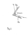
- the first corner 4 is illustrated in detail in figure 2 .
- the first corner 4 is called a reference corner due to the fact that it is provided for adjusting, positioning and fixing the substrate relative to the frame elements 2a and 2b, relative to the frame 2a, 2b, 2c, 2d and thus relative to the carrier 1.
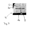
- the first corner 4 comprises a first retainer 6 and a second retainer 7 fixedly attached to the first and second frame elements 2a and 2b, respectively, as illustrated in figure 3 .
- a glass substrate may be positioned in a particular orientation relative to the frame 2a, 2b, 2c, 2d and the carrier 1.
- FIG 4 illustrates two embodiments of a retainer 6, 7 used in the present invention.
- the retainer 6, 7 comprises a supporting surface 8 for supporting a substrate 14.
- the substrate inserted in a retainer gap 9 may be moved so far as to contact an abutment portion 10 of the retainer 6, 7.
- a clamp spring 11 is provided to fix the substrate in a defined position after the adjustment of the substrate in the reference corner 4.
- the clamp spring 11 may have an opening/ closing mechanism.
- the retainer 6, 7 may be constructed without an opening/ closing mechanism.
- the substrate is received and fixed in the retainer 6, 7 by inserting the substrate into the retainer gap 9 in a direction indicated by the arrow S and bringing it into engagement with the retainer 6, 7.
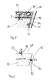
- Figure 5 shows the second corner 5 of the carrier 1 illustrated in figure 1 .
- the second angular corner 5 is defined by a third frame element 2c and a forth frame element 2d.
- Third and fourth retainers 12 and 13 are connected to the third frame element 2c and the forth frame element 2d, respectively.
- the retainers 12 and 13 have the same configuration as the retainers 6 and 7 illustrated in figure 4 .
- the third and fourth retainers 12 and 13 are not fixedly connected to the frame elements 2c and 2d, but movably relative to the respective frame elements 2c and 2d. This is indicated in figure 6 .
- the third and the fourth retainers 12 and 13 are attached to the frame elements 2c and 2d, respectively, by means of linear guides 15 and 16. Therefore, the third and the fourth retainers 12 and 13 are movable relative to the frame members 2c and 2d, respectively, in the direction indicated by arrows c and d in figure 6 .
- the direction is substantially perpendicular to the longitudinal axis of the third and fourth frame members 2c and 2d, respectively, and/or substantially perpendicular to the edge(s) of a substrate inserted and positioned in the first and second retainers 6 and 7.
- a substrate 14 held by the retainers 12 and 13 may thus conduct movements relative to the frame elements 2c and 2d. Consequently, thermal expansion of the carrier 1 may be compensated by the movement of the retainers 12 and 13 by means of linear guides 15 and 16 relative to the third and fourth frame members 2c and 2d.
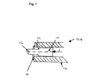
- a linear guide 15, 16 as used in the present invention is shown in figure 7 . It comprises an attachment portion 17a provided on a telescopic member 17 for fixing a retainer 12, 13 thereon.
- the moving portion 17 is guided by a linear bearing 17b.
- the movable member 17 performs the linear movement within the bearing 17b.
- a stopper 18 restricts the movement of the movable member 17 in the direction F by contacting an abutment surface 17c of the movable member 17.
- an elastic element (not shown), e. g. a pressure spring, is provided in a conventional manner such that a force indicated by arrow F, is exerted in the direction of a substrate edge 14 (see also figure 5 ). Due to the arrangement of the retainers 15 and 16 in the opposite corner 5, the force resulting from the forces F provided by the elastic elements of the linear guides 15, 16 urges the substrate 14 in the direction of the reference corner 4 and thus provides a secure and exact position of the substrate in the reference corner 4. Therefore, the position of the substrate 14 relative to the first and second frame elements 2a and 2b is continuously the same regardless of thermal expansions of the carrier 1, production tolerances of the substrate size, and other variations of the substrate size.
- a pressure spring is provided in a conventional manner such that a force indicated by arrow F, is exerted in the direction of a substrate edge 14 (see also figure 5 ). Due to the arrangement of the retainers 15 and 16 in the opposite corner 5, the force resulting from the forces F provided by the elastic elements of the linear guides 15, 16 urges the substrate
- the carrier 1 described above may be used for dynamic or static coating processes. Particularly in static coating processes an edge exclusion 20 may be used in combination with the carrier 1 as shown in figure 8 .
- the edge exclusion 20 is movably installed inside a vacuum chamber. It may be moved in a direction indicated by the arrow M and in the opposite direction relative to the frame 2 and substrate 14. Alternatively, the frame 2 and substrate 14 may be moved relative to the edge exclusion 20. In a first retracted position (not shown) the edge exclusion 20 is spaced from the frame 2 of the carrier 1 such that a protrusion 20c does not engage with the gap 19. In this position of the edge exclusion 20 the carrier 1 is positioned within the vacuum chamber. Before the static coating process is started, the edge exclusion 20 is moved in the direction M towards the frame 2 in order to bring the edge exclusion 20 in a second position (as shown in figure 8 ) thus bringing the protrusion 20c into exact engagement with the gap 19. Then the static coating process may be carried out. In the second position the edge exclusion 20 covers the gap 19 (see figure 5 ) between the outer edge of the substrate 14 and the frame elements 2a, 2b, 2c and 2d.
- the edge exclusion 20 may be fixed to the carrier 1 to be moved through the processing stations together with the carrier 1.
- the edge exclusion 20 comprises a body portion 20a, a lip portion 20b having a free end and a protrusion 20c extending into the gap 19 between the outer edge 14' of a substrate 14 and the inner edge 2' of a frame element 2 of the carrier 1.
- the protrusion 20c may extend into the gap 19 to an appropriate extent such that unwanted particle contamination of carrier components is prevented.
- the body portion 20a substantially extends over the frame element 2 and over the gap 19 along the substantially entire periphery of the edge 14' of the substrate 14 in order to prevent particles from entering into the gap 19 and being deposited on the frame element 2.
- the lip portion 20b has a free end projects over a portion of the substrate surface substantially along the periphery near the edge 14' of the substrate 14.
- the lip 20b is thus the shield or mask for preventing coating particles from being deposited in the outer edge region of the (upper) substrate surface, on the outer edge 14' and on the underside of the substrate 14.
- the underside of the lip 20b of the edge exclusion 20 and a portion of the substrate surface near the edge 14' of the substrate 14 form a clearance 21 having an adjustable width.
- the width is set large enough for preventing "bridging" between the edge exclusion 20 and the substrate 14, on the other hand it is small enough to shield a portion o the substrate surface near the edge 14', the edge 14' and the underside of the substrate 14 effectively from particle deposition by particles entering into the clearance 21.
- the protrusion 20c extending into the gap 19 provides a labyrinth seal for particles entering the clearance 21.
- the protrusion 20c is formed to prevent particles entering into the clearance 21 to be deposited on the frame element 2 by blocking the particles on their (direct) way to the frame element 2. Thus the coating particles are exclusively deposited on the substrate surface and on the edge exclusion 20.
- the protrusion 20bc of the edge exclusion 20 may be moved exactly into the gap 19. This provides for constant conditions during a number of coating processes carried out in the vacuum chamber. Furthermore, any pollution of the carrier components may be prevented, even when the process chamber is vented (causing particles to be detached from components arranged inside the vacuum chamber).
- the combination of the positioning method and device for attaching the substrate to a carrier 1 in a defined position and the edge exclusion 20 as described above provides for a secure, exact and permanent positioning of the substrate 14 relative to frame elements 2a, 2b and relative to the edge exclusion 20. Furthermore, any pollution of the carrier components by particles used for processing the substrate 14 is prevented. By using the described edge exclusion 20 a defined tab on the substrate surface can be masked and particles can be prevented from polluting carrier components. Due to the advantages in positioning the substrate 14 thermal expansion of the carrier 1 may be compensated and the quality of the coating near the edges 14' of the substrates 14 may be improved.
Landscapes
- Container, Conveyance, Adherence, Positioning, Of Wafer (AREA)
- Physical Vapour Deposition (AREA)
- Chemical Vapour Deposition (AREA)
- Processing And Handling Of Plastics And Other Materials For Molding In General (AREA)
- Manufacturing Of Printed Wiring (AREA)
Abstract
Description
- The present invention relates to a substrate support for supporting a substrate to be processed in a vacuum processing chamber, said substrate support comprising: a frame for carrying said substrate; and at least a first fastening means fixedly attached to said frame for aligning said substrate relative to said frame by attaching said substrate to said first fastening means. Furthermore, the invention relates to a substrate processing device for processing a substrate comprising: at least one process chamber; processing tools arranged in said process chamber for processing said substrate; and an edge exclusion projecting over a portion of the substrate surface of a substrate supported in a substrate support and received in said process chamber for preventing processing of a portion of said substrate. Moreover, the invention relates to a method of placing a substrate on a substrate support.
- In the field of processing, e.g. coating, substantially large-size plane substrates, various processing methods are used, e.g. PVD (physical vapor deposition) like sputtering, CVD (chemical vapor deposition), PECVD (plasma enhanced chemical vapor deposition), etc. By applying these processes single layers or multi-layer systems are deposited on glass substrates to produce coated panels, display screens, OLED (organic light emitting diode) panels, thermally insulating glass panels, etc.
- Generally, the layer deposition may be provided in static or in dynamic coating processes. In static coating processes the substrate is positioned on a substrate supporting platform to be coated within a vacuum coating chamber. The substrate is secured to a support platform within a deposition chamber by clamp springs or a clamp frame while being coated.
- In order to prevent deposition of particles on the edge or on the underside of the substrate, the substrate holder may include an edge exclusion or shadow frame for preventing processing of a perimeter portion of the (upper) substrate surface. A particular shadow frame supported on a shadow frame support within the cavity of a processing chamber is disclosed in
US patent No. 6,773,562 B1 . By providing the shadow frame processing gases and plasma are prevented from reaching the edge and the backside of the substrate. - In dynamic coating processes the substrate is fixedly attached to a carrier in order to provide the transport and transfer of the substrate between the various handling and processing chambers. Usually, the carrier comprises a frame extending along the edge of the glass substrate. The glass substrate is fixed in the carrier by clamp springs. During the deposition of coating particles on the substrate, particles may also be deposited on the frame causing particle problems. Particularly, when the carrier is locked in, locked out and transported between various coating chambers, it may be heated up and cooled down at frequent intervals. Due to thermal expansions of the carrier the glass substrate has no defined position relative to the carrier during the processing/ coating steps.
- A number of problems have been identified with respect to the handling and processing of large-size substrates. Particularly, in a static process the transport of glass substrates is difficult and the substrate may be damaged, e. g. by displacement of the substrate arranged on the supporting platform when positioning and aligning the substrate. Furthermore, if the edge exclusion is not properly centred relative to the substrate during the processing steps, the amount of shadowing will be unequal and inexact. Particularly, when depositing a number of layers in different chambers, re-positioning of the substrate may be required after moving the substrate from one processing chamber into the next processing chamber.
- In dynamic processes an exact positioning of the substrate relative to the carrier (and possibly relative to a shadow frame) is difficult to maintain during the complete process.
- It is an object of the present invention to provide a substrate support and a coating device allowing an exact alignment of a glass substrate on the substrate support and preventing the deposition of particles on the substrate support.
- This object is achieved by the provision of a substrate support having the features of
claim 1, a substrate processing device according toclaim 7, and a method of placing a substrate on a substrate support according toclaim 15. - A substrate support for supporting a substrate to be processed in a vacuum processing chamber comprises: a frame for carrying said substrate; and at least a first fastening means fixedly attached to said frame for aligning said substrate relative to said frame by attaching said substrate to said first fastening means. The substrate support further comprises at least a second fastening means movably attached to said frame, said second fastening means being movable relative to said frame and/or movable relative to said substrate attached to said first fastening means, particularly in a direction at least towards and/or away from and edge of said substrate attached to said first fastening means.
- The substrate support may be a substrate carrier for supporting substrates to be transported through a number of processing chambers for processing the glass substrates, particularly for coating the glass substrates. The glass substrates are particularly large-area plane substrates. Fastening means are means for aligning a substrate, for providing reference points for positioning the substrate, for engaging a substrate with the fastening means, and/or for attaching or fixing a substrate in the fastening means.
- The first and second fastening means may comprise a stopper for the abutment of the edge(s) glass substrate, at least one supporting area for supporting the glass substrate and a clamp spring for fixing the glass substrate. The clamp spring may be a flat spring, a compound spring, etc. The substrate may be fixed on the carrier and in contact with the carrier only through the fastening means. No support platform or support surface has to be provided.
- Due to the mobility of the second fastening means thermal movement occurring during the transport of the substrate through lock chambers, unlock chambers, process and treatment chambers may be compensated. Furthermore, by providing a combination of a fixed fastening means and a moveable fastening means, an exact positioning of the substrate may be obtained.
- Particularly, the first fastening means comprises at least a first retainer element and a second retainer element. The first and second retainers may be arranged at a first frame element and a second frame element, respectively, near a reference corner of the frame of the carrier. The substrate may be positioned in a reference position by means of the first and second retainers in a horizontal plane within the positioning space enclosed by the frame of the carrier. Thus, the glass substrate is fixedly positioned relative to the perpendicularly aligned first and second frame elements of the carrier.
- In a preferred embodiment the first fastening means is arranged on said frame to define a reference corner for retaining, aligning and/or fixedly attaching said substrate relative to said substrate support in a reference position. The carrier comprises a reference corner including means for aligning the substrate relative to the carrier frame. For example, a first fastening means may be provided including alignment and fixing means positioned at different sides of the reference corner. The alignment and fixing means comprise a retainer for receiving the substrate, e. g. for engagement of the substrate with the retainer, provide an abutment for the substrate to bring it into a defined position, and a fixing means which may be closed for fixing said substrate in the defined position. The fixing means may be designed to include clamp spring.
- Particularly, the second fastening means comprises at least a third retainer element and a fourth retainer element. The third retainer and/or clamp element and the forth retainer and/or clamp element may be arranged at a third frame element and a forth frame element, respectively. Particularly, the third and the forth retainer and/or clamp are arranged at two sides of a corner which is arranged opposite to the reference corner defined by the first fastening means.
- The first fastening means and the second fastening means may each comprise one, two or more retainers for engagement with the edge of the substrate. The first fastening means, e. g. the retainers of the first fastening means, are fixedly connected to a first and second frame element. The first and second frame elements define a corner which is a reference corner for the alignment of the substrate relative to the carrier. The second fastening means comprises a linear guide means such that the retainers positioned at a third and forth frame element of the carrier are capable of being moved relative to the edge of the substrate and/or relative to the third and fourth frame element, respectively. In this way, the retainers of the second fastening means may be engaged and disengaged with the respective edge of the substrate.
- The second fastening means may be movably attached to the substrate support by means of a linear guide, particularly for guiding said retainer elements on a linear path relative to the frame and/or the edge of a substrate received in said first fastening means in a direction substantially perpendicular to the edge of said substrate. In this way, thermal expansion of the carrier may be compensated as well as production tolerances in the substrate size. The glass substrate may be positioned exactly relative to the frame of the carrier and (if provided) to an edge exclusion.
- It may be noted that the first fastening means and/or the second fastening means or components thereof may also be displaceable in a direction parallel to the edge(s) of the adjusted substrate. Furthermore, the term "fixedly attached" does not exclude a configuration in which a fastening means is fixed to a frame element by appropriate fixing means.
- The second fastening means especially comprises means for exerting a force in the direction towards the edge(s) of the substrate received in said first fastening means. The force exerted in the direction towards the edge(s) of the substrate may be an elastic force. It may be exerted by an elastic element, e.g. by one or more springs, particularly by pressure springs, provided in the linear guidance(s) of the retainer(s) and/or fixing means. The resulting force exerted on the substrate by the second fastening means is substantially directed at the reference corner in order to keep the substrate in a desired position defined by the first fastening means that is fixedly connected with the frame of the carrier. Furthermore, the linear guide means provide for a movement of the second fastening means towards the edge of the substrate and allow, against an elastic force applied by pressure springs integrated in said guide means, to retract the second fastening means from the edge of the substrate.
- The problem is also solved by providing a substrate processing device for processing a substrate comprising: at least one process chamber; processing tools arranged in said process chamber for processing said substrate; and an edge exclusion projecting over a portion of the substrate surface of a substrate supported in a substrate support and received in said process chamber for preventing processing of a portion of said substrate. Said edge exclusion is adapted to provide a labyrinth seal between an edge of said substrate and a frame member of said substrate support.
- Particularly, the substrate processing device is a coating device for depositing a layer and/or a layer system of particular materials on the substrate surface. The process chamber may be a vacuum chamber having processing tools arranged therein. Said processing tools comprise material sources that provide coating material to be deposited on the substrate surface. The coating device usually comprises a number of vacuum coating chambers and/or process chambers to perform a number of coating and/or processing steps on a substrate. As the invention is not limited to particular coating methods, the coating tools may comprise sputter material sources, PVD tools, CVD tools, PECVD equipment, etc.
- The carrier comprises a frame which defines and/or encloses a space. The space is somewhat larger than the area of the substrates to be processed. Therefore, a small gap having a width of a few millimetres is provided between the peripheral edge of the substrate and the frame elements defining the space. The gap may have a width of some millimetres and may be covered by the edge exclusion.
- The term "edge exclusion" is used as a synonym for the terms "shadow frame" or "masking". The inboard portion (lip portion) of the edge exclusion extends over a portion of the substrate surface masking a tab-like edge portion of the substrate surface, thereby forming a small clearance between the underside of the lip portion of the edge exclusion extending over the edge portion of the substrate surface. The lip portion projects inward from the body over the substrate edge. The width of the clearance may be constant or variable, e. g. having steps provided in the underside of the projecting lip portion of the edge exclusion.
- A labyrinth seal in the sense of this invention is a seal which is structured to form a bent, a curve and/or a winding path between the upper surface of the substrate and components of the substrate support, i.e. the carrier such that the probability for particles entering the clearance between the surface of the substrate and the underside of the edge conclusion is very small to reach the frame components (neither in a linear movement nor when being scattered). In other words, the particles have to pass through a long and difficult path to escape from the area of the coating chamber in which particles used for the process are provided.
- According to the present invention the labyrinth seal is formed as a part of the edge exclusion. The edge exclusion projects over portion of the surface of a substrate supported by a carrier and received in the coating chamber in order to prevent processing of a portion of the substrate surface. A part of the edge exclusion may be moved into the gap between the edge(s) of the substrate and the frame of the substrate support to form the labyrinth seal between the frame element and the edge of the substrate.
- The labyrinth seal is implemented by providing a protrusion formed at said edge exclusion. Particularly, the protrusion is provided to extend into the gap between the edge of the aligned substrate and the frame of the carrier when the edge exclusion is moved close to the carrier. The protrusion prevents particles entering the clearance between the underside of the edge exclusion and the upper surface of the glass substrate from passing the gap between the edge of the glass substrate and the carrier components. The protrusion blocks any linear path to the frame or any other component of the carrier for the particles entering the clearance.
- The labyrinth seal is a non-contact sealing. So there is no considerable "bridging" between the substrate and the frame elements. The only contact between the substrate and the carrier is made by the retainers of the fastening means, i.e. the substrate is exclusively supported by the first fastening means and the second fastening means which are in contact only with a small portion of the periphery of the substrate. Therefore, a defined masked tab around the periphery of the substrate may be provided, and bridging between the substrate and components of the carrier may be avoided.
- Particularly, said substrate processing device further comprises a substrate support, particularly a substrate support as described above, for supporting a substrate. The substrate support may support a substrate and carry the substrate through a number of processing chambers, transfer chambers etc. in order to accomplish a substrate transfer and processing of the substrate. Furthermore, by providing a carrier according to the invention (particularly in a static coating process) an exact alignment and positioning of the substrate relative to the carrier, and, if an edge exclusion is provided, relative to the edge exclusion is possible. Thus a defined shadowed tab along the periphery of the substrate surface may be obtained. Coating of the carrier by scattered particles is reduced due to the provision of a labyrinth seal.
- Said substrate support may comprise a frame and a substrate supported in said substrate support, said frame being arranged such that gap is formed between said frame and an edge of said substrate. In fact, the substrate support may be loaded with a substrate to form the gap which is covered by an edge exclusion.
- Particularly, said edge exclusion is arranged within said process chamber. In a preferred embodiment, the edge exclusion is coupled with at least a component of the process chamber, particularly with a chamber wall.
- In a preferred embodiment, said edge exclusion and a substrate support received in said process chamber are arranged movable relative to each other in order to move at least a portion of said edge exclusion into said gap between the edge of said substrate and said frame of said substrate support to form said labyrinth seal. The edge exclusion may be coupled with at least a component of said process chamber and arranged within said process chamber movable, e.g. relative to a chamber wall. Particularly, it may be movable relative to the substrate support arranged within the process chamber. A relative movement means that the edge exclusion may also be fixedly connected with at least a component of the process chamber, and the process chamber may provide means for moving the substrate support towards the edge exclusion. Also, both the edge exclusion and the substrate support may be arranged movable within the process chamber and be able to move towards each other and to move away from each other.
- Particularly, the edge exclusion comprises a body portion for covering said gap between said edge of said substrate and said frame of said substrate support in order to prevent particles from entering into said gap.
- The lip may comprise an end portion having a free end projecting over a portion of said substrate surface to form a clearance between the underside of said end portion of said lip and said portion of the substrate surface. The free end portion projects over the portion of the substrate surface in a contactless manner.
- The labyrinth seal may furthermore comprise a protrusion extending from said edge exclusion into said gap between the edge said substrate and said frame element for preventing particles required for the process to pass said gap in a direction towards said frame element. A particle entering the clearance is blocked by the protrusion from moving further into the direction of the frame that surrounds the substrate, or into the direction of other components of the carrier. The protrusion extends into the gap along substantially the complete periphery of the edge of the substrate. Therefore, a labyrinth seal is provided substantially along the entire periphery of the substrate. Because the protrusion protrudes downward from the underside of the lip projection over the peripheral portion of the substrate surface considerably further than the width of the clearance a direct linear path to the frame is blocked by the protrusion. The protrusion is only interrupted at the positions of the fastening means retaining some small peripheral sections of the edge. The edge exclusion is movably arranged within the process chamber relative to said substrate support such that the protrusion is movable into the gap and retractable from the gap when the processing step has been finished. Thus the substrate carrier can be easily transported into and out of the process chamber. The seal prevents particles used for processing the substrate surface from passing said gap entering said clearance in a direction towards the frame of the carrier.
- A method of placing a substrate on a substrate support, particularly on a substrate support described above, comprises the steps of:
- a. providing at least a first fastening means fixedly attached to a frame of said substrate support, and a second fastening means movably attached to said frame, said second fastening means being movable relative to said frame;
- b. moving said second fastening means in an outward direction to increase a space defined by the position of said first fastening means and said second fastening means between said first fastening means and said second fastening means;
- c. attaching said substrate to said first fastening means;
- d. moving said second fastening means in an inward direction towards an edge of said substrate attached to said first fastening means; and
- e. Attaching said substrate to said second fastening means.
Particularly, step c. includes retaining said substrate in said fastening means, moving the substrate towards abutments of the fastening means in order to adjust the position of the substrate, and locking the substrate in said first fastening means, e. g. by activating a clamp mechanism of said fastening means. Step d. may include retaining said substrate in said fastening means, pressing said substrate in the direction of the first fastening means in order to stabilize the alignment of the substrate. Furthermore, in step d. the fastening means may be moved in an inward direction by a force directed towards an edge of a substrate attached to said first fastening means.
In step e. the second fastening means may exert a force towards the first fastening means so as to press the substrate in a direction of the first fastening means to maintain it in a position defined by the first fastening means.
In a preferred embodiment, attaching said substrate to said first fastening means and/or to said second fastening means is provided by closing a clamp spring of said first fastening means and said second fastening means, respectively, and/or by bringing an edge portion of said substrate into engagement with said first fastening means and said second fastening means, respectively.
When loading a carrier with a glass substrate, the following steps are carried out. First, the carrier is placed in a horizontal position. The clamp springs of the fastening means are opened. The movable retainers are removed against the force of the pressure springs provided in the linear guidances of the movable second fastening means, thereby increasing the space defined by the position of the first and second fastening means. Afterwards, the glass substrate can be received by the retainers of the first fastening means. The substrate is aligned by reference points in the first fastening means, e.g. by abutment surfaces, stoppers, etc. provided in the retainers of the first fastening means.
The substrate may be attached to the first and/or second fastening means by providing the fastening means with at least a clamp that may be opened and closed when removing the substrate from the fastening means and attaching the substrate to the fastening means, respectively. Before transporting the carrier into a process chamber, the clamp springs of the retainers are closed.
In another embodiment, the fastening means may comprise retainers that do not have an opening/closing mechanism. The substrate is attached to the fastening means by engaging the substrate with at least one retainer of the fastening means. The engagement is made by moving the substrate edge into the retainer. The disengagement is made by retracting the substrate from the retainer.
This means that in step c) the substrate is moved in a space between the first fastening means and the second fastening means on a level appropriate for the engagement with the first fastening means. Afterwards, when the substrate has been attached to the first fastening means, the second fastening means is brought into engagement with the substrate by the movement of the second fastening means, particularly by retainers that are suitable for receiving a thirds and/or a forth edge of the substrate.
Afterwards, the movable retainers of the second fastening means are released such that the elastic force exerted by the pressure springs of the guidance means make the retainers of the second fastening means move towards the third and forth edge of the glass substrate until they abut on the respective edge of the glass substrate. The force of the pressure springs presses the glass substrate into the reference corner of the carrier.
Particularly, said first fastening means is placed in a reference corner of a frame of said substrate support, and said substrate is aligned by placing said substrate in a defined position determined by said first fastening means.
The first fastening means and the second fastening means may comprise at least two retainers and/or clamps each. The retainers and/or clamps of the first fastening means are fixed with respect to the frame of the carrier. They define a reference corner for aligning the substrate relative to the carrier. The retainers and/or clamps of the second fastening means, on the other hand, are movable to be able to move towards the substrate edge in order to engage with the substrate edge. By providing a linear guide means and an elastic means the retainers of the second fastening means may exert a force towards the edge of the substrate, thus pressing the substrate into the direction of the reference corner.
The method may furthermore comprise a further step: - f. moving an edge exclusion into a gap between the edge of said substrate and a frame element of said substrate support.
- The general idea of the invention is to use a carrier for the transport of large-area glass substrates as well in a static as in a dynamic coating process. In order to ensure an exact aligning and positioning of glass substrate relative to the edge exclusion a system for the alignment of the substrate on the carrier is integrated in the carrier. Furthermore, in order to prevent coating of the carrier more reliably a labyrinth seal is used between the carrier components and the substrate edge.
- In a static coating process the edge exclusion is particularly integrated in the process chamber. The labyrinth seal is generated by moving a protrusion of the edge exclusion into a gap between the edge of the substrate and the carrier frame before starting the coating process.
- In a dynamic coating process the edge exclusion may be integrated in the carrier itself, i.e. it may be a component of the carrier. The labyrinth seal is provided by the arrangement of the protrusion of the edge exclusion in the gap between the edge of the substrate and the carrier frame.
- Unloading the substrate from the carrier includes performing the steps of loading in reverse order. I.e. when removing the substrate from the substrate support the second fastening means is moved outwards relative to the substrate in a direction away from an edge of the substrate. Afterwards, the substrate is removed from first fastening means, either by opening the clamp springs of the retainer, or by moving the substrate in a direction away from the first fastening means to release the substrate from the retainers.
- The features described above are claimed in any combination thereof. Particularly, it has been recognized by the inventors that a combination of the inventive edge exclusion and the positioning mechanism for aligning and fixing the substrate results in a transportable substrate carrier that allows to maintain a permanently exact position of the substrate relative to the carrier, and an edge exclusion preventing the substrate carrier from being polluted by process particles effectively.
- Further objects and advantages result from the following description of specific embodiments relating to the figures. The figures show in
- Fig. 1
- a view of a carrier according to the present invention;
- Fig. 2
- a detail of the carrier according to
fig. 1 ; - Fig. 3
- the detail of
fig. 2 including retainers; - Fig. 4
- two embodiments of retainers used in a carrier according to the present invention;
- Fig. 5
- another detail of the carrier according to
fig. 1 ; - Fig. 6
- the detail of
fig. 5 including retainers; - Fig. 7
- a linear guide means used in accordance with the present invention; and
- Fig. 8
- an edge exclusion provided in accordance with the present invention.
-
Figure 1 shows asubstrate carrier 1 according to the present invention. Thesubstrate carrier 1 comprises a frame consisting offrame elements substrate 14. A substrate which is somewhat smaller than the interior space 3 may be positioned therein and held/ fixed within theframe - The
frame angular corner 4 defined by afirst frame element 2a and asecond frame element 2b, and an opposite secondangular corner 5 defined by athird frame element 2c and afourth frame element 2d. - The
first corner 4 is illustrated in detail infigure 2 . Thefirst corner 4 is called a reference corner due to the fact that it is provided for adjusting, positioning and fixing the substrate relative to theframe elements frame carrier 1. - The
first corner 4 comprises afirst retainer 6 and asecond retainer 7 fixedly attached to the first andsecond frame elements figure 3 . In this way a glass substrate may be positioned in a particular orientation relative to theframe carrier 1. -
Figure 4 illustrates two embodiments of aretainer retainer surface 8 for supporting asubstrate 14. The substrate inserted in aretainer gap 9 may be moved so far as to contact anabutment portion 10 of theretainer - In one of the embodiments a
clamp spring 11 is provided to fix the substrate in a defined position after the adjustment of the substrate in thereference corner 4. Theclamp spring 11 may have an opening/ closing mechanism. - In the alternative embodiment, the
retainer retainer retainer gap 9 in a direction indicated by the arrow S and bringing it into engagement with theretainer -
Figure 5 shows thesecond corner 5 of thecarrier 1 illustrated infigure 1 . The secondangular corner 5 is defined by athird frame element 2c and aforth frame element 2d. Third andfourth retainers third frame element 2c and theforth frame element 2d, respectively. Basically, theretainers retainers figure 4 . - However, the third and
fourth retainers frame elements respective frame elements figure 6 . The third and thefourth retainers frame elements linear guides fourth retainers frame members figure 6 . The direction is substantially perpendicular to the longitudinal axis of the third andfourth frame members second retainers - A
substrate 14 held by theretainers frame elements carrier 1 may be compensated by the movement of theretainers linear guides fourth frame members - A
linear guide figure 7 . It comprises anattachment portion 17a provided on atelescopic member 17 for fixing aretainer portion 17 is guided by alinear bearing 17b. Themovable member 17 performs the linear movement within thebearing 17b. Astopper 18 restricts the movement of themovable member 17 in the direction F by contacting anabutment surface 17c of themovable member 17. - Furthermore, an elastic element (not shown), e. g. a pressure spring, is provided in a conventional manner such that a force indicated by arrow F, is exerted in the direction of a substrate edge 14 (see also
figure 5 ). Due to the arrangement of theretainers opposite corner 5, the force resulting from the forces F provided by the elastic elements of thelinear guides substrate 14 in the direction of thereference corner 4 and thus provides a secure and exact position of the substrate in thereference corner 4. Therefore, the position of thesubstrate 14 relative to the first andsecond frame elements carrier 1, production tolerances of the substrate size, and other variations of the substrate size. - The
carrier 1 described above may be used for dynamic or static coating processes. Particularly in static coating processes anedge exclusion 20 may be used in combination with thecarrier 1 as shown infigure 8 . - The
edge exclusion 20 is movably installed inside a vacuum chamber. It may be moved in a direction indicated by the arrow M and in the opposite direction relative to theframe 2 andsubstrate 14. Alternatively, theframe 2 andsubstrate 14 may be moved relative to theedge exclusion 20. In a first retracted position (not shown) theedge exclusion 20 is spaced from theframe 2 of thecarrier 1 such that aprotrusion 20c does not engage with thegap 19. In this position of theedge exclusion 20 thecarrier 1 is positioned within the vacuum chamber. Before the static coating process is started, theedge exclusion 20 is moved in the direction M towards theframe 2 in order to bring theedge exclusion 20 in a second position (as shown infigure 8 ) thus bringing theprotrusion 20c into exact engagement with thegap 19. Then the static coating process may be carried out. In the second position theedge exclusion 20 covers the gap 19 (seefigure 5 ) between the outer edge of thesubstrate 14 and theframe elements - In another embodiment, particularly in connection with a dynamic coating process, the
edge exclusion 20 may be fixed to thecarrier 1 to be moved through the processing stations together with thecarrier 1. - According to
figure 8 theedge exclusion 20 comprises abody portion 20a, a lip portion 20b having a free end and aprotrusion 20c extending into thegap 19 between the outer edge 14' of asubstrate 14 and the inner edge 2' of aframe element 2 of thecarrier 1. Theprotrusion 20c may extend into thegap 19 to an appropriate extent such that unwanted particle contamination of carrier components is prevented. - The
body portion 20a substantially extends over theframe element 2 and over thegap 19 along the substantially entire periphery of the edge 14' of thesubstrate 14 in order to prevent particles from entering into thegap 19 and being deposited on theframe element 2. - The lip portion 20b has a free end projects over a portion of the substrate surface substantially along the periphery near the edge 14' of the
substrate 14. The lip 20b is thus the shield or mask for preventing coating particles from being deposited in the outer edge region of the (upper) substrate surface, on the outer edge 14' and on the underside of thesubstrate 14. - The underside of the lip 20b of the
edge exclusion 20 and a portion of the substrate surface near the edge 14' of thesubstrate 14 form aclearance 21 having an adjustable width. On the one hand the width is set large enough for preventing "bridging" between theedge exclusion 20 and thesubstrate 14, on the other hand it is small enough to shield a portion o the substrate surface near the edge 14', the edge 14' and the underside of thesubstrate 14 effectively from particle deposition by particles entering into theclearance 21. - The
protrusion 20c extending into thegap 19 provides a labyrinth seal for particles entering theclearance 21. Theprotrusion 20c is formed to prevent particles entering into theclearance 21 to be deposited on theframe element 2 by blocking the particles on their (direct) way to theframe element 2. Thus the coating particles are exclusively deposited on the substrate surface and on theedge exclusion 20. - Due to the exact positioning of the
substrate 14 relative to theframe 2 the protrusion 20bc of the edge exclusion 20 (mask) may be moved exactly into thegap 19. This provides for constant conditions during a number of coating processes carried out in the vacuum chamber. Furthermore, any pollution of the carrier components may be prevented, even when the process chamber is vented (causing particles to be detached from components arranged inside the vacuum chamber). - The combination of the positioning method and device for attaching the substrate to a
carrier 1 in a defined position and theedge exclusion 20 as described above provides for a secure, exact and permanent positioning of thesubstrate 14 relative to frameelements edge exclusion 20. Furthermore, any pollution of the carrier components by particles used for processing thesubstrate 14 is prevented. By using the describededge exclusion 20 a defined tab on the substrate surface can be masked and particles can be prevented from polluting carrier components. Due to the advantages in positioning thesubstrate 14 thermal expansion of thecarrier 1 may be compensated and the quality of the coating near the edges 14' of thesubstrates 14 may be improved.
Claims (19)
- A substrate support (1) for supporting a substrate (14) to be processed in a vacuum processing chamber, said substrate support (1) comprising:a frame (2a, 2b, 2c, 2d) for carrying said substrate (14); andat least a first fastening means (6, 7) fixedly attached to said frame (2a, 2b, 2c, 2d) for aligning said substrate (14) relative to said frame (2a, 2b, 2e, 2d) by attaching said substrate (14) to said first fastening means (6, 7),characterized in thatsaid substrate support (1) further comprises at least a second fastening means (12, 13) movably attached to said frame (2a, 2b, 2c, 2d), said second fastening means (12, 13) being movable relative to said frame (2a, 2b, 2c, 2d) and/or movable relative to said substrate (14) attached to said first fastening means (6, 7), particularly in a direction at least towards and/or away from and edge (14') of said substrate (14) attached to said first fastening means (6, 7).
- The substrate support (1) according to claim 1,
characterized in that
said first fastening means (6, 7) comprises at least a first retainer element (6) and a second retainer element (7). - The substrate support (1) according to claim 1 or 2,
characterized in that
said first fastening means (6, 7) is arranged on said frame (2a, 2b) to define a reference corner (4) for retaining, aligning and/or fixedly attaching said substrate (14) relative to said substrate support (1) in a reference position. - The substrate support (1) according to any of the previous claims,
characterized in that
said second fastening means (12, 13) comprises at least a third retainer element (12) and a fourth retainer element (13). - The substrate support (1) according to any of the previous claims,
characterized in that
said second fastening means (12, 13) is movably attached to said substrate support (1) by means of a linear guide (15, 16), particularly for guiding said retainer elements (12, 13) on a linear path relative to the frame (2a, 2b, 2c, 2d) and/or relative to the edge (14') of substrate (14) received in said first fastening means (6, 7) in a direction substantially perpendicular to the edge (14') of said substrate (14). - The substrate support (1) according to any of the previous claims,
characterized in that
said second fastening means (12, 13) comprises means for exerting a force in the direction towards the edge(s) (14') of said substrate (14) received in said first fastening means (6, 7). - A substrate processing device for processing a substrate (14) comprising:at least one process chamber,processing tools arranged in said process chamber for processing said substrate (14); andan edge exclusion (20) projecting over a portion of the substrate surface of a substrate (14) supported in a substrate support (1) and received in said process chamber for preventing processing of a portion of said substrate (14),characterized in thatsaid edge exclusion (20) is adapted to provide a labyrinth seal between an edge (14') of said substrate (14) and a frame member (2a, 2b, 2c, 2d) of said substrate support (1).
- The substrate processing device according to claim 7,
characterized in that
said substrate processing device further comprises a substrate support (1), particularly a substrate support (1) according to any of the previous claims 1 to 6, for supporting a substrate (14). - The substrate processing device according to claim 8,
characterized in that
said substrate support (1) comprises a frame (2a, 2b, 2c, 2d), said frame (2a, 2b, 2c, 2d) being arranged such that a gap (19) is formed between said frame (2a, 2b, 2c, 2d) and an edge (14') of a substrate (14) supported in said substrate support (1). - The substrate processing device according to any of the previous claims 7 to 9,
characterised in that
said edge exclusion (20) is arranged within said process chamber. - The substrate processing device according to claim 10,
characterized in that
said edge exclusion (20) and a substrate support (1) received in said process chamber are arranged movable relative to each other in order to move at least a portion of said edge exclusion (20) into said gap (19) between the edge (14') of a substrate (14) supported by said substrate support (1) and said frame (2a, 2b, 2c, 2d) of said substrate support (1) to form said labyrinth seal. - The substrate processing device according to any of the previous claims 7 to 11,
characterized in that
said edge exclusion (20) comprises a body portion (20a) for covering said gap (19) between said edge (14') of said substrate (14) and said frame (2a, 2b, 2c, 2d) of said substrate support (1) in order to prevent particles from entering into said gap (19). - The substrate processing device according to any of the previous claims 7 to 12,
characterized in that
said edge exclusion (20) comprises an end portion (20b) having a free end projecting over a portion of said substrate surface to form a clearance (21) between the underside ot said end portion (20b) of said edge exclusion (20) and said portion of the substrate surface. - The substrate processing device according to any of the previous claims 7 to 13,
characterized in that
said labyrinth seal comprises a protrusion (20c) extending from said body portion (20a) of said edge exclusion (20), wherein said edge exclusion (20) is movably arranged within said process chamber relative to said substrate support such that said protrusion (20c) is movable into said gap (19) between the edge (14') of said substrate (14) and said frame element (2a, 2b, 2c, 2d) for preventing particles used for processing the substrate surface from passing said gap in a direction towards said frame (2a, 2b, 2c, 2d). - A method of placing a substrate (14) on a substrate support (1), particularly on a substrate Support (1) according to any of the previous claims 1 to 6, comprising the steps of:a. providing at least a first fastening means (6, 7) fixedly attached to a frame (2a, 2b, 2c, 2d) of said substrate support (1), and a second fastening means (12, 13) movably attached to said frame (2a, 2b, 2c, 2d), said second fastening means (12, 13) being movable relative to said frame;b. moving said second fastening means (12, 13) in an outward direction to increase a space defined by the position of said first fastening means (6, 7) and said second fastening means (12, 13)between said first fastening means (6, 7) and said second fastening means (12, 13);c. attaching said substrate (14) to said first fastening means (6, 7);d. moving said second fastening means (12, 13) in an inward direction towards an edge (14') of said substrate (14) attached to said first fastening means (6, 7) ande. Attaching said substrate (14) to said second fastening means (12, 13).
- The method according to claim 15,
characterized in that
in step d. the fastening means are moved in an inward direction by a force directed towards an edge (14') of a substrate (14) attached to said first fastening means (6, 7). - The method according to claim 15 or 16,
characterized in that
attaching said substrate (14) to said first fastening means (6, 7) and/or to said second fastening means (12, 13) is provided by closing a clamp spring of said first fastening means (6, 7) and said second fastening means (12, 13), respectively, and/or by bringing an edge portion (14') of said substrate (14) into engagement with said first fastening means (6, 7) and said second fastening means (12, 13), respectively. - The method according to any of the previous claims 15 to 17,
characterized in that
said first fastening means (6, 7) is placed in a reference corner (4) of a frame (2a, 2b, 2c, 2d) of said substrate support (1), and said substrate (14) is aligned by placing said substrate in a defined position determined by said first fastening means (6, 7). - The method according to any of the previous claims 15 to 18,
characterized in that
said method comprises a further step:f moving an edge exclusion (20) into a gap (19) between the edge (14') of said substrate (14) and a frame element (2a, 2b, 2c, 2d) of said substrate support (1).
Priority Applications (10)
| Application Number | Priority Date | Filing Date | Title |
|---|---|---|---|
| PL07107164T PL1998366T3 (en) | 2007-04-27 | 2007-04-27 | A device for processing the substrate and a method for positioning the substrate |
| DE602007006772T DE602007006772D1 (en) | 2007-04-27 | 2007-04-27 | Substrate processing apparatus and method for placing a substrate |
| EP07107164A EP1998366B1 (en) | 2007-04-27 | 2007-04-27 | Substrate processing device and method of placing a substrate |
| AT07107164T ATE469437T1 (en) | 2007-04-27 | 2007-04-27 | SUBSTRATE PROCESSING APPARATUS AND METHOD FOR PLACING A SUBSTRATE |
| TW096149790A TWI371078B (en) | 2007-04-27 | 2007-12-24 | Substrate support, substrate processing device and method of placing a substrate |
| KR1020080006206A KR100957885B1 (en) | 2007-04-27 | 2008-01-21 | Substrate support, substrate processing apparatus and substrate placement method |
| US12/108,320 US8323412B2 (en) | 2007-04-27 | 2008-04-23 | Substrate support, substrate processing device and method of placing a substrate |
| JP2008116237A JP5068216B2 (en) | 2007-04-27 | 2008-04-25 | Substrate support, substrate processing apparatus, and substrate mounting method |
| CN2008100950780A CN101299416B (en) | 2007-04-27 | 2008-04-28 | Substrate holder, substrate processing device and method for placing substrate |
| US13/664,246 US20130055953A1 (en) | 2007-04-27 | 2012-10-30 | Substrate support, substrate processing device and method of placing a substrate |
Applications Claiming Priority (1)
| Application Number | Priority Date | Filing Date | Title |
|---|---|---|---|
| EP07107164A EP1998366B1 (en) | 2007-04-27 | 2007-04-27 | Substrate processing device and method of placing a substrate |
Publications (2)
| Publication Number | Publication Date |
|---|---|
| EP1998366A1 true EP1998366A1 (en) | 2008-12-03 |
| EP1998366B1 EP1998366B1 (en) | 2010-05-26 |
Family
ID=38327074
Family Applications (1)
| Application Number | Title | Priority Date | Filing Date |
|---|---|---|---|
| EP07107164A Not-in-force EP1998366B1 (en) | 2007-04-27 | 2007-04-27 | Substrate processing device and method of placing a substrate |
Country Status (9)
| Country | Link |
|---|---|
| US (2) | US8323412B2 (en) |
| EP (1) | EP1998366B1 (en) |
| JP (1) | JP5068216B2 (en) |
| KR (1) | KR100957885B1 (en) |
| CN (1) | CN101299416B (en) |
| AT (1) | ATE469437T1 (en) |
| DE (1) | DE602007006772D1 (en) |
| PL (1) | PL1998366T3 (en) |
| TW (1) | TWI371078B (en) |
Cited By (3)
| Publication number | Priority date | Publication date | Assignee | Title |
|---|---|---|---|---|
| US8323412B2 (en) | 2007-04-27 | 2012-12-04 | Applied Materials, Inc. | Substrate support, substrate processing device and method of placing a substrate |
| WO2013020589A1 (en) | 2011-08-09 | 2013-02-14 | Applied Materials, Inc. | Adjustable mask |
| WO2014139594A1 (en) * | 2013-03-15 | 2014-09-18 | Applied Materials, Inc. | Carrier for a substrate and method for carrying a substrate |
Families Citing this family (7)
| Publication number | Priority date | Publication date | Assignee | Title |
|---|---|---|---|---|
| JP5359698B2 (en) * | 2009-08-31 | 2013-12-04 | 豊田合成株式会社 | Compound semiconductor manufacturing apparatus, compound semiconductor manufacturing method, and compound semiconductor |
| CN105189812B (en) * | 2013-03-15 | 2017-10-20 | 应用材料公司 | Carrier for substrate |
| CN105452523B (en) * | 2013-08-02 | 2019-07-16 | 应用材料公司 | Holding arrangement for substrate and the device and method using the holding arrangement for substrate |
| CN107109619A (en) * | 2014-12-29 | 2017-08-29 | 应用材料公司 | Masking substrate shelters arrangement, the depositing device for the layer deposition on substrate and for cleaning the method for sheltering arrangement during for deposition processes |
| CN109300835B (en) * | 2017-07-25 | 2021-04-09 | 北京北方华创微电子装备有限公司 | A wafer support structure, preheating chamber and semiconductor processing equipment |
| CN109338335B (en) * | 2018-10-16 | 2020-09-08 | 深圳市华星光电技术有限公司 | Shadow frame structure for chemical vapor deposition |
| CN112981372B (en) * | 2019-12-12 | 2024-02-13 | Asm Ip私人控股有限公司 | Substrate support plate, substrate processing apparatus including same, and substrate processing method |
Citations (9)
| Publication number | Priority date | Publication date | Assignee | Title |
|---|---|---|---|---|
| EP0284003A1 (en) | 1987-03-25 | 1988-09-28 | Svg Lithography Systems, Inc. | Reticle frame assembly |
| JPH05226214A (en) * | 1992-02-10 | 1993-09-03 | Canon Inc | Substrate holding apparatus |
| US5957651A (en) * | 1995-06-08 | 1999-09-28 | Kokusai Electric Co., Ltd. | Substrate carrying apparatus |
| US5989342A (en) * | 1996-01-30 | 1999-11-23 | Dainippon Screen Mfg, Co., Ltd. | Apparatus for substrate holding |
| US6033480A (en) * | 1994-02-23 | 2000-03-07 | Applied Materials, Inc. | Wafer edge deposition elimination |
| US6106631A (en) * | 1997-10-16 | 2000-08-22 | Sharp Kabushiki Kaisha | Plasma processing apparatus |
| US20030196604A1 (en) * | 2002-04-22 | 2003-10-23 | Stmicroelectronics, Inc. | Padded clamp ring with edge exclusion for deposition of thick AlCu/AlSiCu/Cu metal alloy layers |
| US6773562B1 (en) | 1998-02-20 | 2004-08-10 | Applied Materials, Inc. | Shadow frame for substrate processing |
| US20050117142A1 (en) | 2003-10-27 | 2005-06-02 | Asml Netherlands B.V. | Assembly of a reticle holder and a reticle |
Family Cites Families (9)
| Publication number | Priority date | Publication date | Assignee | Title |
|---|---|---|---|---|
| JPS5684502A (en) * | 1979-12-13 | 1981-07-09 | Fujitsu Ltd | Positioning device for plate |
| JPS6111222Y2 (en) * | 1980-12-19 | 1986-04-09 | ||
| JP4101966B2 (en) | 1999-03-24 | 2008-06-18 | 三菱電機株式会社 | Thin film deposition equipment |
| JP4416892B2 (en) | 2000-01-04 | 2010-02-17 | 株式会社アルバック | Mask and vacuum processing equipment |
| KR100548711B1 (en) * | 2000-03-16 | 2006-02-02 | 에이에스엠엘 네델란즈 비.브이. | Substrate Holder for Lithographic Apparatus |
| JP2005223217A (en) | 2004-02-06 | 2005-08-18 | Ulvac Japan Ltd | Substrate positioning mechanism and in-line vacuum processor equipped therewith |
| JP4549697B2 (en) | 2004-03-04 | 2010-09-22 | 株式会社アルバック | Film forming apparatus and film forming method |
| JP4494832B2 (en) | 2004-03-11 | 2010-06-30 | 株式会社アルバック | Alignment apparatus and film forming apparatus |
| ATE469437T1 (en) | 2007-04-27 | 2010-06-15 | Applied Materials Inc | SUBSTRATE PROCESSING APPARATUS AND METHOD FOR PLACING A SUBSTRATE |
-
2007
- 2007-04-27 AT AT07107164T patent/ATE469437T1/en not_active IP Right Cessation
- 2007-04-27 DE DE602007006772T patent/DE602007006772D1/en active Active
- 2007-04-27 EP EP07107164A patent/EP1998366B1/en not_active Not-in-force
- 2007-04-27 PL PL07107164T patent/PL1998366T3/en unknown
- 2007-12-24 TW TW096149790A patent/TWI371078B/en not_active IP Right Cessation
-
2008
- 2008-01-21 KR KR1020080006206A patent/KR100957885B1/en active Active
- 2008-04-23 US US12/108,320 patent/US8323412B2/en active Active
- 2008-04-25 JP JP2008116237A patent/JP5068216B2/en active Active
- 2008-04-28 CN CN2008100950780A patent/CN101299416B/en active Active
-
2012
- 2012-10-30 US US13/664,246 patent/US20130055953A1/en not_active Abandoned
Patent Citations (10)
| Publication number | Priority date | Publication date | Assignee | Title |
|---|---|---|---|---|
| EP0284003A1 (en) | 1987-03-25 | 1988-09-28 | Svg Lithography Systems, Inc. | Reticle frame assembly |
| JPH05226214A (en) * | 1992-02-10 | 1993-09-03 | Canon Inc | Substrate holding apparatus |
| US5471279A (en) | 1992-02-10 | 1995-11-28 | Canon Kabushiki Kaisha | Apparatus and method for supporting a substrate |
| US6033480A (en) * | 1994-02-23 | 2000-03-07 | Applied Materials, Inc. | Wafer edge deposition elimination |
| US5957651A (en) * | 1995-06-08 | 1999-09-28 | Kokusai Electric Co., Ltd. | Substrate carrying apparatus |
| US5989342A (en) * | 1996-01-30 | 1999-11-23 | Dainippon Screen Mfg, Co., Ltd. | Apparatus for substrate holding |
| US6106631A (en) * | 1997-10-16 | 2000-08-22 | Sharp Kabushiki Kaisha | Plasma processing apparatus |
| US6773562B1 (en) | 1998-02-20 | 2004-08-10 | Applied Materials, Inc. | Shadow frame for substrate processing |
| US20030196604A1 (en) * | 2002-04-22 | 2003-10-23 | Stmicroelectronics, Inc. | Padded clamp ring with edge exclusion for deposition of thick AlCu/AlSiCu/Cu metal alloy layers |
| US20050117142A1 (en) | 2003-10-27 | 2005-06-02 | Asml Netherlands B.V. | Assembly of a reticle holder and a reticle |
Cited By (3)
| Publication number | Priority date | Publication date | Assignee | Title |
|---|---|---|---|---|
| US8323412B2 (en) | 2007-04-27 | 2012-12-04 | Applied Materials, Inc. | Substrate support, substrate processing device and method of placing a substrate |
| WO2013020589A1 (en) | 2011-08-09 | 2013-02-14 | Applied Materials, Inc. | Adjustable mask |
| WO2014139594A1 (en) * | 2013-03-15 | 2014-09-18 | Applied Materials, Inc. | Carrier for a substrate and method for carrying a substrate |
Also Published As
| Publication number | Publication date |
|---|---|
| PL1998366T3 (en) | 2010-12-31 |
| KR20080096357A (en) | 2008-10-30 |
| ATE469437T1 (en) | 2010-06-15 |
| EP1998366B1 (en) | 2010-05-26 |
| US8323412B2 (en) | 2012-12-04 |
| CN101299416A (en) | 2008-11-05 |
| KR100957885B1 (en) | 2010-05-13 |
| TWI371078B (en) | 2012-08-21 |
| DE602007006772D1 (en) | 2010-07-08 |
| US20130055953A1 (en) | 2013-03-07 |
| US20080295773A1 (en) | 2008-12-04 |
| JP5068216B2 (en) | 2012-11-07 |
| TW200843024A (en) | 2008-11-01 |
| JP2008291361A (en) | 2008-12-04 |
| CN101299416B (en) | 2010-09-29 |
Similar Documents
| Publication | Publication Date | Title |
|---|---|---|
| EP1998366B1 (en) | Substrate processing device and method of placing a substrate | |
| KR102330725B1 (en) | Thin film encapsulation processing system and process kit permitting low-pressure tool replacement | |
| US5037262A (en) | Holding device for a disk and application therefor | |
| JP2918780B2 (en) | Alignment of shadow frames and large planar substrates on heated supports | |
| EP0398589B1 (en) | Perimeter wafer seal and method of using the same | |
| US20120263569A1 (en) | Substrate holders and methods of substrate mounting | |
| KR20180006496A (en) | Susceptor position and rotator, and methods of use | |
| CN102859030A (en) | Coating device, and method for operating a coating device with a shielding plate | |
| KR102219198B1 (en) | Holding arrangement for substrates and apparatus and method using the same | |
| US20090291203A1 (en) | Substrate tray and film forming apparatus | |
| US20050257742A1 (en) | Replaceable shielding apparatus | |
| US6221166B1 (en) | Multi-thermal zone shielding apparatus | |
| KR200485369Y1 (en) | Aluminum coated or ceramic parts for substrate drive system | |
| US7581916B2 (en) | Sample introduction and transfer system and method | |
| WO2020025101A1 (en) | Apparatus with movable shield carrier | |
| AT515435A2 (en) | Wafer support system | |
| JP6591570B2 (en) | Self-locking holder for substrates | |
| JP7393401B2 (en) | Vacuum processing equipment | |
| CN204144233U (en) | Base plate supports carrier and the system for the treatment of substrate | |
| JP7393400B2 (en) | Vacuum processing equipment | |
| KR20060112012A (en) | Door opening and closing device of semiconductor manufacturing equipment | |
| KR20240044527A (en) | Process gas containment using elastomeric bodies aligned with reactor interfaces |
Legal Events
| Date | Code | Title | Description |
|---|---|---|---|
| PUAI | Public reference made under article 153(3) epc to a published international application that has entered the european phase |
Free format text: ORIGINAL CODE: 0009012 |
|
| 17P | Request for examination filed |
Effective date: 20070522 |
|
| AK | Designated contracting states |
Kind code of ref document: A1 Designated state(s): AT BE BG CH CY CZ DE DK EE ES FI FR GB GR HU IE IS IT LI LT LU LV MC MT NL PL PT RO SE SI SK TR |
|
| AX | Request for extension of the european patent |
Extension state: AL BA HR MK RS |
|
| RTI1 | Title (correction) |
Free format text: SUBSTRATE PROCESSING DEVICE AND METHOD OF PLACING A SUBSTRATE |
|
| AKX | Designation fees paid |
Designated state(s): AT BE BG CH CY CZ DE DK EE ES FI FR GB GR HU IE IS IT LI LT LU LV MC MT NL PL PT RO SE SI SK TR |
|
| GRAP | Despatch of communication of intention to grant a patent |
Free format text: ORIGINAL CODE: EPIDOSNIGR1 |
|
| GRAS | Grant fee paid |
Free format text: ORIGINAL CODE: EPIDOSNIGR3 |
|
| GRAA | (expected) grant |
Free format text: ORIGINAL CODE: 0009210 |
|
| AK | Designated contracting states |
Kind code of ref document: B1 Designated state(s): AT BE BG CH CY CZ DE DK EE ES FI FR GB GR HU IE IS IT LI LT LU LV MC MT NL PL PT RO SE SI SK TR |
|
| REG | Reference to a national code |
Ref country code: GB Ref legal event code: FG4D |
|
| REG | Reference to a national code |
Ref country code: CH Ref legal event code: EP |
|
| REG | Reference to a national code |
Ref country code: IE Ref legal event code: FG4D |
|
| REF | Corresponds to: |
Ref document number: 602007006772 Country of ref document: DE Date of ref document: 20100708 Kind code of ref document: P |
|
| REG | Reference to a national code |
Ref country code: NL Ref legal event code: VDEP Effective date: 20100526 |
|
| LTIE | Lt: invalidation of european patent or patent extension |
Effective date: 20100526 |
|
| PG25 | Lapsed in a contracting state [announced via postgrant information from national office to epo] |
Ref country code: SE Free format text: LAPSE BECAUSE OF FAILURE TO SUBMIT A TRANSLATION OF THE DESCRIPTION OR TO PAY THE FEE WITHIN THE PRESCRIBED TIME-LIMIT Effective date: 20100526 Ref country code: LT Free format text: LAPSE BECAUSE OF FAILURE TO SUBMIT A TRANSLATION OF THE DESCRIPTION OR TO PAY THE FEE WITHIN THE PRESCRIBED TIME-LIMIT Effective date: 20100526 |
|
| PG25 | Lapsed in a contracting state [announced via postgrant information from national office to epo] |
Ref country code: SI Free format text: LAPSE BECAUSE OF FAILURE TO SUBMIT A TRANSLATION OF THE DESCRIPTION OR TO PAY THE FEE WITHIN THE PRESCRIBED TIME-LIMIT Effective date: 20100526 Ref country code: LV Free format text: LAPSE BECAUSE OF FAILURE TO SUBMIT A TRANSLATION OF THE DESCRIPTION OR TO PAY THE FEE WITHIN THE PRESCRIBED TIME-LIMIT Effective date: 20100526 Ref country code: IS Free format text: LAPSE BECAUSE OF FAILURE TO SUBMIT A TRANSLATION OF THE DESCRIPTION OR TO PAY THE FEE WITHIN THE PRESCRIBED TIME-LIMIT Effective date: 20100926 Ref country code: FI Free format text: LAPSE BECAUSE OF FAILURE TO SUBMIT A TRANSLATION OF THE DESCRIPTION OR TO PAY THE FEE WITHIN THE PRESCRIBED TIME-LIMIT Effective date: 20100526 Ref country code: AT Free format text: LAPSE BECAUSE OF FAILURE TO SUBMIT A TRANSLATION OF THE DESCRIPTION OR TO PAY THE FEE WITHIN THE PRESCRIBED TIME-LIMIT Effective date: 20100526 |
|
| PG25 | Lapsed in a contracting state [announced via postgrant information from national office to epo] |
Ref country code: CY Free format text: LAPSE BECAUSE OF FAILURE TO SUBMIT A TRANSLATION OF THE DESCRIPTION OR TO PAY THE FEE WITHIN THE PRESCRIBED TIME-LIMIT Effective date: 20100602 |
|
| REG | Reference to a national code |
Ref country code: PL Ref legal event code: T3 |
|
| PG25 | Lapsed in a contracting state [announced via postgrant information from national office to epo] |
Ref country code: NL Free format text: LAPSE BECAUSE OF FAILURE TO SUBMIT A TRANSLATION OF THE DESCRIPTION OR TO PAY THE FEE WITHIN THE PRESCRIBED TIME-LIMIT Effective date: 20100526 Ref country code: EE Free format text: LAPSE BECAUSE OF FAILURE TO SUBMIT A TRANSLATION OF THE DESCRIPTION OR TO PAY THE FEE WITHIN THE PRESCRIBED TIME-LIMIT Effective date: 20100526 Ref country code: DK Free format text: LAPSE BECAUSE OF FAILURE TO SUBMIT A TRANSLATION OF THE DESCRIPTION OR TO PAY THE FEE WITHIN THE PRESCRIBED TIME-LIMIT Effective date: 20100526 Ref country code: PT Free format text: LAPSE BECAUSE OF FAILURE TO SUBMIT A TRANSLATION OF THE DESCRIPTION OR TO PAY THE FEE WITHIN THE PRESCRIBED TIME-LIMIT Effective date: 20100927 Ref country code: GR Free format text: LAPSE BECAUSE OF FAILURE TO SUBMIT A TRANSLATION OF THE DESCRIPTION OR TO PAY THE FEE WITHIN THE PRESCRIBED TIME-LIMIT Effective date: 20100827 |
|
| PG25 | Lapsed in a contracting state [announced via postgrant information from national office to epo] |
Ref country code: CZ Free format text: LAPSE BECAUSE OF FAILURE TO SUBMIT A TRANSLATION OF THE DESCRIPTION OR TO PAY THE FEE WITHIN THE PRESCRIBED TIME-LIMIT Effective date: 20100526 Ref country code: RO Free format text: LAPSE BECAUSE OF FAILURE TO SUBMIT A TRANSLATION OF THE DESCRIPTION OR TO PAY THE FEE WITHIN THE PRESCRIBED TIME-LIMIT Effective date: 20100526 Ref country code: BE Free format text: LAPSE BECAUSE OF FAILURE TO SUBMIT A TRANSLATION OF THE DESCRIPTION OR TO PAY THE FEE WITHIN THE PRESCRIBED TIME-LIMIT Effective date: 20100526 Ref country code: SK Free format text: LAPSE BECAUSE OF FAILURE TO SUBMIT A TRANSLATION OF THE DESCRIPTION OR TO PAY THE FEE WITHIN THE PRESCRIBED TIME-LIMIT Effective date: 20100526 |
|
| PLBE | No opposition filed within time limit |
Free format text: ORIGINAL CODE: 0009261 |
|
| STAA | Information on the status of an ep patent application or granted ep patent |
Free format text: STATUS: NO OPPOSITION FILED WITHIN TIME LIMIT |
|
| 26N | No opposition filed |
Effective date: 20110301 |
|
| REG | Reference to a national code |
Ref country code: DE Ref legal event code: R097 Ref document number: 602007006772 Country of ref document: DE Effective date: 20110228 |
|
| PG25 | Lapsed in a contracting state [announced via postgrant information from national office to epo] |
Ref country code: MC Free format text: LAPSE BECAUSE OF NON-PAYMENT OF DUE FEES Effective date: 20110430 |
|
| PG25 | Lapsed in a contracting state [announced via postgrant information from national office to epo] |
Ref country code: MT Free format text: LAPSE BECAUSE OF FAILURE TO SUBMIT A TRANSLATION OF THE DESCRIPTION OR TO PAY THE FEE WITHIN THE PRESCRIBED TIME-LIMIT Effective date: 20100526 |
|
| REG | Reference to a national code |
Ref country code: IE Ref legal event code: MM4A |
|
| PG25 | Lapsed in a contracting state [announced via postgrant information from national office to epo] |
Ref country code: IE Free format text: LAPSE BECAUSE OF NON-PAYMENT OF DUE FEES Effective date: 20110427 |
|
| REG | Reference to a national code |
Ref country code: DE Ref legal event code: R082 Ref document number: 602007006772 Country of ref document: DE Representative=s name: ZIMMERMANN & PARTNER, DE Ref country code: DE Ref legal event code: R082 Ref document number: 602007006772 Country of ref document: DE Representative=s name: ZIMMERMANN & PARTNER PATENTANWAELTE MBB, DE |
|
| PG25 | Lapsed in a contracting state [announced via postgrant information from national office to epo] |
Ref country code: LU Free format text: LAPSE BECAUSE OF NON-PAYMENT OF DUE FEES Effective date: 20110427 |
|
| PG25 | Lapsed in a contracting state [announced via postgrant information from national office to epo] |
Ref country code: TR Free format text: LAPSE BECAUSE OF FAILURE TO SUBMIT A TRANSLATION OF THE DESCRIPTION OR TO PAY THE FEE WITHIN THE PRESCRIBED TIME-LIMIT Effective date: 20100526 Ref country code: BG Free format text: LAPSE BECAUSE OF FAILURE TO SUBMIT A TRANSLATION OF THE DESCRIPTION OR TO PAY THE FEE WITHIN THE PRESCRIBED TIME-LIMIT Effective date: 20100826 |
|
| PG25 | Lapsed in a contracting state [announced via postgrant information from national office to epo] |
Ref country code: HU Free format text: LAPSE BECAUSE OF FAILURE TO SUBMIT A TRANSLATION OF THE DESCRIPTION OR TO PAY THE FEE WITHIN THE PRESCRIBED TIME-LIMIT Effective date: 20100526 Ref country code: ES Free format text: LAPSE BECAUSE OF FAILURE TO SUBMIT A TRANSLATION OF THE DESCRIPTION OR TO PAY THE FEE WITHIN THE PRESCRIBED TIME-LIMIT Effective date: 20100906 |
|
| REG | Reference to a national code |
Ref country code: CH Ref legal event code: NV Representative=s name: MICHELI AND CIE SA, CH |
|
| REG | Reference to a national code |
Ref country code: FR Ref legal event code: PLFP Year of fee payment: 10 |
|
| REG | Reference to a national code |
Ref country code: FR Ref legal event code: PLFP Year of fee payment: 11 |
|
| REG | Reference to a national code |
Ref country code: FR Ref legal event code: PLFP Year of fee payment: 12 |
|
| PGFP | Annual fee paid to national office [announced via postgrant information from national office to epo] |
Ref country code: PL Payment date: 20190321 Year of fee payment: 13 |
|
| PGFP | Annual fee paid to national office [announced via postgrant information from national office to epo] |
Ref country code: IT Payment date: 20190423 Year of fee payment: 13 Ref country code: DE Payment date: 20190418 Year of fee payment: 13 |
|
| PGFP | Annual fee paid to national office [announced via postgrant information from national office to epo] |
Ref country code: FR Payment date: 20190424 Year of fee payment: 13 |
|
| PGFP | Annual fee paid to national office [announced via postgrant information from national office to epo] |
Ref country code: CH Payment date: 20190418 Year of fee payment: 13 |
|
| PGFP | Annual fee paid to national office [announced via postgrant information from national office to epo] |
Ref country code: GB Payment date: 20190418 Year of fee payment: 13 |
|
| REG | Reference to a national code |
Ref country code: DE Ref legal event code: R119 Ref document number: 602007006772 Country of ref document: DE |
|
| REG | Reference to a national code |
Ref country code: CH Ref legal event code: PL |
|
| PG25 | Lapsed in a contracting state [announced via postgrant information from national office to epo] |
Ref country code: DE Free format text: LAPSE BECAUSE OF NON-PAYMENT OF DUE FEES Effective date: 20201103 Ref country code: CH Free format text: LAPSE BECAUSE OF NON-PAYMENT OF DUE FEES Effective date: 20200430 Ref country code: LI Free format text: LAPSE BECAUSE OF NON-PAYMENT OF DUE FEES Effective date: 20200430 Ref country code: FR Free format text: LAPSE BECAUSE OF NON-PAYMENT OF DUE FEES Effective date: 20200430 |
|
| GBPC | Gb: european patent ceased through non-payment of renewal fee |
Effective date: 20200427 |
|
| PG25 | Lapsed in a contracting state [announced via postgrant information from national office to epo] |
Ref country code: GB Free format text: LAPSE BECAUSE OF NON-PAYMENT OF DUE FEES Effective date: 20200427 |
|
| PG25 | Lapsed in a contracting state [announced via postgrant information from national office to epo] |
Ref country code: IT Free format text: LAPSE BECAUSE OF NON-PAYMENT OF DUE FEES Effective date: 20200427 |
|
| PG25 | Lapsed in a contracting state [announced via postgrant information from national office to epo] |
Ref country code: PL Free format text: LAPSE BECAUSE OF NON-PAYMENT OF DUE FEES Effective date: 20200427 |