EP1998302B1 - Mesotube burn-in manifold - Google Patents
Mesotube burn-in manifold Download PDFInfo
- Publication number
- EP1998302B1 EP1998302B1 EP08157006A EP08157006A EP1998302B1 EP 1998302 B1 EP1998302 B1 EP 1998302B1 EP 08157006 A EP08157006 A EP 08157006A EP 08157006 A EP08157006 A EP 08157006A EP 1998302 B1 EP1998302 B1 EP 1998302B1
- Authority
- EP
- European Patent Office
- Prior art keywords
- chamber
- tube
- vacuum
- burn
- exterior
- Prior art date
- Legal status (The legal status is an assumption and is not a legal conclusion. Google has not performed a legal analysis and makes no representation as to the accuracy of the status listed.)
- Ceased
Links
Images

Classifications
-
- H—ELECTRICITY
- H01—ELECTRIC ELEMENTS
- H01J—ELECTRIC DISCHARGE TUBES OR DISCHARGE LAMPS
- H01J9/00—Apparatus or processes specially adapted for the manufacture, installation, removal, maintenance of electric discharge tubes, discharge lamps, or parts thereof; Recovery of material from discharge tubes or lamps
- H01J9/38—Exhausting, degassing, filling, or cleaning vessels
- H01J9/385—Exhausting vessels
-
- H—ELECTRICITY
- H01—ELECTRIC ELEMENTS
- H01J—ELECTRIC DISCHARGE TUBES OR DISCHARGE LAMPS
- H01J17/00—Gas-filled discharge tubes with solid cathode
- H01J17/38—Cold-cathode tubes
- H01J17/40—Cold-cathode tubes with one cathode and one anode, e.g. glow tubes, tuning-indicator glow tubes, voltage-stabiliser tubes, voltage-indicator tubes
-
- H—ELECTRICITY
- H01—ELECTRIC ELEMENTS
- H01J—ELECTRIC DISCHARGE TUBES OR DISCHARGE LAMPS
- H01J9/00—Apparatus or processes specially adapted for the manufacture, installation, removal, maintenance of electric discharge tubes, discharge lamps, or parts thereof; Recovery of material from discharge tubes or lamps
- H01J9/38—Exhausting, degassing, filling, or cleaning vessels
- H01J9/395—Filling vessels
-
- H—ELECTRICITY
- H01—ELECTRIC ELEMENTS
- H01J—ELECTRIC DISCHARGE TUBES OR DISCHARGE LAMPS
- H01J9/00—Apparatus or processes specially adapted for the manufacture, installation, removal, maintenance of electric discharge tubes, discharge lamps, or parts thereof; Recovery of material from discharge tubes or lamps
- H01J9/44—Factory adjustment of completed discharge tubes or lamps to comply with desired tolerances
- H01J9/445—Aging of tubes or lamps, e.g. by "spot knocking"
Definitions
- Embodiments relate to the manufacture of flame detector tubes and vacuum tubes. Embodiments also relate to sputtering, gettering, vacuum chambers, manifolds, and process gas delivery systems.
- Vacuum tubes the predecessors of transistors and diodes, are air tight chambers with cathodes and anodes.
- the air is largely evacuated from the tube, hence the name vacuum tube.
- the tube's cathode is held at a lower voltage than the tube's anode so that electrons are accelerated from the cathode to the anode.
- electrons move to the anode, they collide with air molecules knocking even more electrons loose and thereby amplifying the number of electrons.
- the cathode is heated to produce thermionic electrons.
- photons are allowed to impact the cathode to cause the release of photoelectrons.
- Vacuum tubes are rarely used in circuitry any more. They are, however, often used in light detection. Some tubes are so sensitive that a single photon can cause an electron to leave the cathode and induce a large avalanche of secondary and tertiary electrons that reach the anode.
- One type of photon sensitive tube is a flame detector tube. A flame detector tube is sensitive to the photons produced by flames.
- a tube's anode and cathode are subjected to a constant and necessary bombardment of electrons and ions. The result is the etching and sputtering of the cathode and anode.
- the anode and cathode are often made from or coated with resistant materials such as tungsten and molybdenum while still being consistent with the demands for the proper work function.
- the gas in the tube is chosen to be one that will not damage the anodes and cathodes too much nor react with other tube materials consistent with proper breakdown characteristics. Neon and a neon/hydrogen mix are often used as tube gasses because they are fairly light and nonreactive.
- Burn-in is a process in which the tube is run at an elevated voltage to sputter the surfaces smooth.
- the materials and gases used in vacuum tubes are specifically chosen to minimize sputtering.
- Engineering decisions for extended tube life also cause long burn-in times.
- FR-A-2 317 761 discloses a vacuum tube burn-in process for CRT displays.
- a burn-in manifold has a first chamber, a cavity, and a lid.
- the lid covers the cavity to form a second chamber.
- An interior wall is shared by the first chamber and the second chamber.
- the interior wall has an interior wall opening and that the lid has an exterior opening.
- a vacuum tube's fill tube reachs into the first chamber by passing through the exterior opening, through the second chamber and through the interior wall opening.
- An exterior seal seals the fill tube to the exterior wall to prevent environmental gas from entering the second chamber.
- An interior seal seals the fill tube to the interior wall to prevent gas from passing from the first chamber into the second chamber.
- O rings can be used as interior seals and as exterior seals.
- Fig. 1 illustrates a burn-in manifold with a lid in accordance with aspects of the embodiments
- Fig. 2 illustrates a burn-in manifold with a lid and installed vacuum tubes in accordance with aspects of the embodiments
- Fig. 3 illustrates a burn-in manifold in accordance with aspects of the embodiments
- Fig. 4 illustrates a burn-in manifold lid in accordance with aspects of the embodiments
- Fig. 5 illustrates a burn-in manifold cavity in accordance with aspects of the embodiments
- Fig. 6 illustrates a cut view of a burn-in manifold lid in accordance with aspects of the embodiments.
- Fig. 7 illustrates high level flow diagram of using a burn-in manifold in accordance with aspects of the embodiments.
- a two chamber system with fill gas in one chamber and vacuum in the other provides a means of burning in one or more vacuum tubes while avoiding contamination from environmental gases.
- Vacuum tubes are often burned in after being sealed. Some processes burn-in the tubes before sealing them. The burn in process can take days and provide ample opportunity for environmental gases to contaminate the vacuum tube.
- the vacuum tube's fill tube passes through the vacuum chamber and into the fill gas chamber. Environmental gases leaking past the fill tube are evacuated by the vacuum. Similarly, fill gas leaking past the fill tube is also evacuated to vacuum. As such, the environmental gases are drawn away before contaminating the vacuum tube.
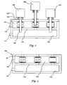
- Fig. 1 illustrates a burn-in manifold with a lid 107 in accordance with aspects of the embodiments.
- the lid 107 has exterior openings 105, burn in connectors 107, exterior seals 104, and a gasket 108.
- the exterior seals can be O-rings that rest in cups 115.
- a manifold body has a cavity 112 and a first chamber 113 separated by an interior wall 116.
- the interior wall has interior wall openings 114 as well as seals 104 and cups 115.
- Spacer rings 109, 110 can press the seals 104 against the interior wall 116 and lid 107.
- a ported spacer ring 110 has ports 111 passing from the spacer ring's center to its exterior.
- a vacuum port 118 can be connected to a vacuum source while a fill port 117 can be connected to a gas source.
- a vacuum tube 119 has a body 101, fill tube 103 and tube connectors 102.
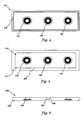
- Fig. 2 illustrates a burn-in manifold with a lid 107 and installed vacuum tubes 201, 202 in accordance with aspects of the embodiments.
- the burn-in manifold of Fig. 2 is the same as that of Fig. 1 with the exception that the lid 107 and spacer rings are installed.
- Vacuum tubes 201 have been pressed through the exterior openings, through the spacer rings, through the interior openings, and into the first chamber.
- a fill gas in the first chamber 113 will pass into the vacuum tubes 201.
- Fill gas leaking through the interior openings will b evacuated out the vacuum port 118 and will not pass into the outside atmosphere.
- environmental gases leaking through the exterior openings will be evacuated to vacuum and will not enter the first chamber 113. This is particularly important because otherwise a single bad seal could contaminate every vacuum tube.
- the vacuum tubes 201 have their tube connectors 102 mated to the lids burn-in connectors. As such, the tubes can be burned in.
- One vacuum tube 202 is illustrated as pressed into a ported spacer ring.
- the fill tube is exposed to vacuum such that environmental gas is evacuated from the vacuum tube and out the vacuum port 118.
- the interior seals and exterior seals minimize the leakage of gases, but can not be trusted to completely prevent all leakage for the entire time that the vacuum tubes burn-in.
- a burn-in manifold designed for a single tube at a time benefits from the dual chamber arrangement because otherwise it would depend on a single seal and no vacuum evacuation.
- the dual chamber arrangement is particularly advantageous for a multiple tube manifold such as those illustrated. The reason is a single chamber manifold system contaminates all the vacuum tubes when a single seal fails. Furthermore, single seal failures can easily occur during an entire burn in cycle.
- the dual chamber arrangement is resistant to contamination because it is designed to work properly in spite of less than perfect seals.
- Fig. 3 illustrates a burn-in manifold 300 in accordance with aspects of the embodiments.
- the burn-in manifold of Fig. 3 is the same as that of Fig. 2 with the exception of having no lid.
- the burn-in manifold 300 has a permanent exterior wall 301.
- the exterior wall 301 has exterior openings, seals, and cups.
- Fig. 4 illustrates a burn-in manifold lid 107 in accordance with aspects of the embodiments.
- the lid 107 has a gasket 108, exterior openings 105, seals 104, cups 115, and gasket 108.
- Fig. 5 illustrates a burn-in manifold cavity in accordance with aspects of the embodiments.
- the cavity 112 is surrounded by cavity walls 501 with the interior wall 116 forming the cavity 112 bottom.
- the interior wall 116 has interior openings 114, seals 104, cups 115, and gasket 108.
- Fig. 6 illustrates a cut view of a lid 600 with recessed cups 601 in accordance with aspects of the embodiments.
- the lid 600 has exterior openings 105, a gasket 108, and seals 104.
- a recessed cup 601 can hold a seal 104 such as on O ring and can be less expensive to produce.
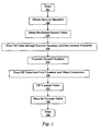
- Fig. 7 illustrates high level flow diagram of using a burn-in manifold in accordance with aspects of the embodiments.
- a burn-in manifold is obtained 702 and vacuum tubes are obtained 703.
- the vacuum tubes' fill tubes are pressed through the manifolds exterior openings such that they reach into the spacer rings but not into the interior openings 705.
- the second chamber is evacuated 705 which also evacuates the vacuum tubes.
- the fill tubes are then pressed through the interior openings such that the tube connectors and burn-in connectors mate 706.
- Fill gas is passed into the first chamber such that the vacuum tubes are filled 707 and then the vacuum tubes are burned in 708.
- the burn in process is done 709 and the vacuum tubes can be sealed and packaged for sale.
Landscapes
- Engineering & Computer Science (AREA)
- Manufacturing & Machinery (AREA)
- Manufacture Of Electron Tubes, Discharge Lamp Vessels, Lead-In Wires, And The Like (AREA)
- Sampling And Sample Adjustment (AREA)
- Examining Or Testing Airtightness (AREA)
- Measurement Of Radiation (AREA)
Description
- Embodiments relate to the manufacture of flame detector tubes and vacuum tubes. Embodiments also relate to sputtering, gettering, vacuum chambers, manifolds, and process gas delivery systems.
- Vacuum tubes, the predecessors of transistors and diodes, are air tight chambers with cathodes and anodes. The air is largely evacuated from the tube, hence the name vacuum tube. The tube's cathode is held at a lower voltage than the tube's anode so that electrons are accelerated from the cathode to the anode. As electrons move to the anode, they collide with air molecules knocking even more electrons loose and thereby amplifying the number of electrons. In many tubes, the cathode is heated to produce thermionic electrons. In other tubes, photons are allowed to impact the cathode to cause the release of photoelectrons.
- Vacuum tubes are rarely used in circuitry any more. They are, however, often used in light detection. Some tubes are so sensitive that a single photon can cause an electron to leave the cathode and induce a large avalanche of secondary and tertiary electrons that reach the anode. One type of photon sensitive tube is a flame detector tube. A flame detector tube is sensitive to the photons produced by flames.
- In operation, a tube's anode and cathode are subjected to a constant and necessary bombardment of electrons and ions. The result is the etching and sputtering of the cathode and anode. To provide long tube life, the anode and cathode are often made from or coated with resistant materials such as tungsten and molybdenum while still being consistent with the demands for the proper work function. Similarly, the gas in the tube is chosen to be one that will not damage the anodes and cathodes too much nor react with other tube materials consistent with proper breakdown characteristics. Neon and a neon/hydrogen mix are often used as tube gasses because they are fairly light and nonreactive.
- In the manufacture of vacuum tubes, a burn-in period is often required. When first produced, anodes and cathodes are rough. The rough surfaces affect the electric fields and result in inconsistent and occasionally even damaging electron flows and sputtering effects. Burn-in is a process in which the tube is run at an elevated voltage to sputter the surfaces smooth. The materials and gases used in vacuum tubes, however, are specifically chosen to minimize sputtering. Engineering decisions for extended tube life also cause long burn-in times. Some burn-in procedures must be performed before the vacuum tube is sealed. As such, there is ample opportunity for environmental gases to contaminate the inside of the vacuum tube. Systems and methods for contamination free burn-in of non-sealed vacuum tubes are needed.
- Examples of apparatus utilising vacuum force and vacuum chambers can be found in
EP-A-1,193,031 andUS-A-2003/0019812 .
FR-A-2 317 761 - The following summary is provided to facilitate an understanding of some of the innovative features unique to the embodiments and is not intended to be a full description. A full appreciation of the various aspects of the embodiments can be gained by taking the entire specification, claims, drawings, and abstract as a whole.
- It is therefore an aspect of the embodiments that a burn-in manifold has a first chamber, a cavity, and a lid. The lid covers the cavity to form a second chamber. An interior wall is shared by the first chamber and the second chamber.
- It is also an aspect of the present invention that the interior wall has an interior wall opening and that the lid has an exterior opening. A vacuum tube's fill tube reachs into the first chamber by passing through the exterior opening, through the second chamber and through the interior wall opening. An exterior seal seals the fill tube to the exterior wall to prevent environmental gas from entering the second chamber. An interior seal seals the fill tube to the interior wall to prevent gas from passing from the first chamber into the second chamber. O rings can be used as interior seals and as exterior seals.
- The accompanying figures, in which like reference numerals refer to identical or functionally similar elements throughout the separate views and which are incorporated in and form a part of the specification, further illustrate aspects of the embodiments and, together with the background, brief summary, and detailed description serve to explain the principles of the embodiments.
-
Fig. 1 illustrates a burn-in manifold with a lid in accordance with aspects of the embodiments; -
Fig. 2 illustrates a burn-in manifold with a lid and installed vacuum tubes in accordance with aspects of the embodiments; -
Fig. 3 illustrates a burn-in manifold in accordance with aspects of the embodiments; -
Fig. 4 illustrates a burn-in manifold lid in accordance with aspects of the embodiments; -
Fig. 5 illustrates a burn-in manifold cavity in accordance with aspects of the embodiments; -
Fig. 6 illustrates a cut view of a burn-in manifold lid in accordance with aspects of the embodiments; and -
Fig. 7 illustrates high level flow diagram of using a burn-in manifold in accordance with aspects of the embodiments. - The particular values and configurations discussed in these non-limiting examples can be varied and are cited merely to illustrate at least one embodiment and are not intended to limit the scope thereof. In general, the figures are not to scale.
- A two chamber system with fill gas in one chamber and vacuum in the other provides a means of burning in one or more vacuum tubes while avoiding contamination from environmental gases. Vacuum tubes are often burned in after being sealed. Some processes burn-in the tubes before sealing them. The burn in process can take days and provide ample opportunity for environmental gases to contaminate the vacuum tube. The vacuum tube's fill tube passes through the vacuum chamber and into the fill gas chamber. Environmental gases leaking past the fill tube are evacuated by the vacuum. Similarly, fill gas leaking past the fill tube is also evacuated to vacuum. As such, the environmental gases are drawn away before contaminating the vacuum tube.
-
Fig. 1 illustrates a burn-in manifold with alid 107 in accordance with aspects of the embodiments. Thelid 107 hasexterior openings 105, burn inconnectors 107,exterior seals 104, and agasket 108. The exterior seals can be O-rings that rest incups 115. A manifold body has acavity 112 and afirst chamber 113 separated by aninterior wall 116. The interior wall hasinterior wall openings 114 as well asseals 104 and cups 115. Spacer rings 109, 110 can press theseals 104 against theinterior wall 116 andlid 107. A portedspacer ring 110 hasports 111 passing from the spacer ring's center to its exterior. Avacuum port 118 can be connected to a vacuum source while afill port 117 can be connected to a gas source. Avacuum tube 119 has abody 101, filltube 103 andtube connectors 102. -
Fig. 2 illustrates a burn-in manifold with alid 107 and installedvacuum tubes Fig. 2 is the same as that ofFig. 1 with the exception that thelid 107 and spacer rings are installed.Vacuum tubes 201 have been pressed through the exterior openings, through the spacer rings, through the interior openings, and into the first chamber. A fill gas in thefirst chamber 113 will pass into thevacuum tubes 201. Fill gas leaking through the interior openings will b evacuated out thevacuum port 118 and will not pass into the outside atmosphere. Similarly, environmental gases leaking through the exterior openings will be evacuated to vacuum and will not enter thefirst chamber 113. This is particularly important because otherwise a single bad seal could contaminate every vacuum tube. Thevacuum tubes 201 have theirtube connectors 102 mated to the lids burn-in connectors. As such, the tubes can be burned in. - One
vacuum tube 202 is illustrated as pressed into a ported spacer ring. The fill tube is exposed to vacuum such that environmental gas is evacuated from the vacuum tube and out thevacuum port 118. - The interior seals and exterior seals minimize the leakage of gases, but can not be trusted to completely prevent all leakage for the entire time that the vacuum tubes burn-in. A burn-in manifold designed for a single tube at a time benefits from the dual chamber arrangement because otherwise it would depend on a single seal and no vacuum evacuation. The dual chamber arrangement is particularly advantageous for a multiple tube manifold such as those illustrated. The reason is a single chamber manifold system contaminates all the vacuum tubes when a single seal fails. Furthermore, single seal failures can easily occur during an entire burn in cycle. The dual chamber arrangement is resistant to contamination because it is designed to work properly in spite of less than perfect seals.
-
Fig. 3 illustrates a burn-inmanifold 300 in accordance with aspects of the embodiments. The burn-in manifold ofFig. 3 is the same as that ofFig. 2 with the exception of having no lid. Instead of a lid, the burn-inmanifold 300 has apermanent exterior wall 301. Like the lid, theexterior wall 301 has exterior openings, seals, and cups. -
Fig. 4 illustrates a burn-inmanifold lid 107 in accordance with aspects of the embodiments. Thelid 107 has agasket 108,exterior openings 105, seals 104,cups 115, andgasket 108. -
Fig. 5 illustrates a burn-in manifold cavity in accordance with aspects of the embodiments. Thecavity 112 is surrounded bycavity walls 501 with theinterior wall 116 forming thecavity 112 bottom. Theinterior wall 116 hasinterior openings 114, seals 104,cups 115, andgasket 108. -
Fig. 6 illustrates a cut view of alid 600 with recessedcups 601 in accordance with aspects of the embodiments. As with the lids in other figures, thelid 600 hasexterior openings 105, agasket 108, and seals 104. A recessedcup 601 can hold aseal 104 such as on O ring and can be less expensive to produce. -
Fig. 7 illustrates high level flow diagram of using a burn-in manifold in accordance with aspects of the embodiments. After the start 701 a burn-in manifold is obtained 702 and vacuum tubes are obtained 703. The vacuum tubes' fill tubes are pressed through the manifolds exterior openings such that they reach into the spacer rings but not into theinterior openings 705. The second chamber is evacuated 705 which also evacuates the vacuum tubes. The fill tubes are then pressed through the interior openings such that the tube connectors and burn-in connectors mate 706. Fill gas is passed into the first chamber such that the vacuum tubes are filled 707 and then the vacuum tubes are burned in 708. The burn in process is done 709 and the vacuum tubes can be sealed and packaged for sale. - It will be appreciated that variations of the above-disclosed and other features and functions, or alternatives thereof, may be desirably combined into many other different systems or applications. Also that various presently unforeseen or unanticipated alternatives, modifications, variations or improvements therein may be subsequently made by those skilled in the art which are also intended to be encompassed by the following claims.
Claims (7)
- A vacuum tube burn-in manifold system comprising:a first chamber (113) comprising a fill gas and a second chamber (112) comprising a vacuum, wherein the first chamber (113) and the second chamber (112) are separated by an interior wall (116);a vacuum port (118) in the second chamber (112);a fill port (117) in the first chamber (113);a plurality of interior openings (114) in the interior wall (116), each opening including a seal (104) and adapted to sealably receive a vacuum tube fill tube (103);a plurality of exterior openings (105) in an exterior wall (107, 301) corresponding with the interior openings (114) of the interior wall, each exterior opening (105) including a seal (104) and adapted to sealably receive a vacuum tube fill tube (103);wherein each of the interior openings (114) and corresponding exterior openings (105) are separated by a spacer (109,110).
- The system of claim 1 wherein the seals (104) are O-rings.
- The system of claim 2 wherein the spacer (109, 110) is positioned within the first chamber (113) such that a vacuum tube fill tube (103) reaches into the second chamber (112) by passing through the exterior opening (105), through the spacer (109, 110) and through the interior opening (114).
- The system of claim 3 wherein the spacer (110) includes a port (111).
- The system of claim 4 further comprising a burn-in connector (106);
wherein a received vacuum tube (119) comprises a body (101), a tube connector (102), and the fill tube (103); and
wherein the tube connector (102) mates to the burn-in connector (106) when the fill tube (103) reaches into the first chamber (113). - A system as claimed in any preceding claim, wherein the system includes a lid (107) covering a cavity forming the second chamber (112), and wherein the exterior openings (105) are formed in the lid (107).
- A system as claimed in any preceding claim, wherein evacuating air from the second chamber (112) prevents air from leaking into the first chamber (113) and also prevents air from leaking into the vacuum tube (119).
Applications Claiming Priority (1)
| Application Number | Priority Date | Filing Date | Title |
|---|---|---|---|
| US11/807,561 US7918706B2 (en) | 2007-05-29 | 2007-05-29 | Mesotube burn-in manifold |
Publications (3)
| Publication Number | Publication Date |
|---|---|
| EP1998302A2 EP1998302A2 (en) | 2008-12-03 |
| EP1998302A3 EP1998302A3 (en) | 2011-01-26 |
| EP1998302B1 true EP1998302B1 (en) | 2012-11-21 |
Family
ID=39769225
Family Applications (1)
| Application Number | Title | Priority Date | Filing Date |
|---|---|---|---|
| EP08157006A Ceased EP1998302B1 (en) | 2007-05-29 | 2008-05-27 | Mesotube burn-in manifold |
Country Status (4)
| Country | Link |
|---|---|
| US (1) | US7918706B2 (en) |
| EP (1) | EP1998302B1 (en) |
| JP (1) | JP2009021219A (en) |
| CN (1) | CN101320668A (en) |
Cited By (1)
| Publication number | Priority date | Publication date | Assignee | Title |
|---|---|---|---|---|
| US10549214B2 (en) | 2017-03-10 | 2020-02-04 | Savannah River Nuclear Solutions, Llc | Device for residue handling minimization with vacuum-assisted separations |
Families Citing this family (3)
| Publication number | Priority date | Publication date | Assignee | Title |
|---|---|---|---|---|
| US7893615B2 (en) * | 2007-09-18 | 2011-02-22 | Honeywell International, Inc. | Ultra violet flame sensor with run-on detection |
| US7750284B2 (en) * | 2008-07-25 | 2010-07-06 | Honeywell International Inc. | Mesotube with header insulator |
| CN104538223A (en) * | 2015-01-04 | 2015-04-22 | 沈阳华德海泰电子有限公司 | Self-cleaning vacuum switch tube high-pressure aging system |
Citations (2)
| Publication number | Priority date | Publication date | Assignee | Title |
|---|---|---|---|---|
| FR2317761A1 (en) * | 1975-06-27 | 1977-02-04 | Rca Corp | ELECTRICAL TREATMENT PROCESS OF ASSEMBLED CATHODIC TUBES |
| EP1168410A1 (en) * | 1999-03-31 | 2002-01-02 | Kabushiki Kaisha Toshiba | Method for manufacturing flat image display and flat image display |
Family Cites Families (17)
| Publication number | Priority date | Publication date | Assignee | Title |
|---|---|---|---|---|
| US4665740A (en) | 1984-08-22 | 1987-05-19 | Nippondenso Co., Ltd. | Combustion process sensor |
| JPH0668947B2 (en) | 1990-01-08 | 1994-08-31 | 浜松ホトニクス株式会社 | Method for forming photocathode |
| US5443416A (en) | 1993-09-09 | 1995-08-22 | Cybeq Systems Incorporated | Rotary union for coupling fluids in a wafer polishing apparatus |
| US5763888A (en) | 1995-01-30 | 1998-06-09 | Ametek Aerospace Products, Inc. | High temperature gas stream optical flame sensor and method for fabricating same |
| JPH09270085A (en) | 1996-04-01 | 1997-10-14 | Hamamatsu Photonics Kk | Smoke production detector |
| US5941699A (en) | 1997-05-08 | 1999-08-24 | Mr. Heater, Inc. | Shutoff system for gas fired appliances |
| US6784430B2 (en) | 1999-02-08 | 2004-08-31 | General Electric Company | Interdigitated flame sensor, system and method |
| US6171513B1 (en) | 1999-04-30 | 2001-01-09 | International Business Machines Corporation | Chemical-mechanical polishing system having a bi-material wafer backing film and two-piece wafer carrier |
| US6344414B1 (en) | 1999-04-30 | 2002-02-05 | International Business Machines Corporation | Chemical-mechanical polishing system having a bi-material wafer backing film assembly |
| US6558540B2 (en) * | 2000-06-26 | 2003-05-06 | Berger Instruments, Inc. | Exhaust gas collection system for supercritical fluid chromatography |
| EP1193031A1 (en) * | 2000-09-29 | 2002-04-03 | Infineon Technologies SC300 GmbH & Co. KG | Arrangement for polishing disk-like objects |
| US6780378B2 (en) | 2001-06-28 | 2004-08-24 | Gas Technology Institute | Method for measuring concentrations of gases and vapors using controlled flames |
| US6784460B2 (en) * | 2002-10-10 | 2004-08-31 | Agilent Technologies, Inc. | Chip shaping for flip-chip light emitting diode |
| US7244946B2 (en) | 2004-05-07 | 2007-07-17 | Walter Kidde Portable Equipment, Inc. | Flame detector with UV sensor |
| US7202794B2 (en) | 2004-07-20 | 2007-04-10 | General Monitors, Inc. | Flame detection system |
| JP2007165478A (en) | 2005-12-12 | 2007-06-28 | National Univ Corp Shizuoka Univ | Photocathode and photodetector |
| US7456412B2 (en) | 2007-04-11 | 2008-11-25 | Honeywell International Inc. | Insulator for tube having conductive case |
-
2007
- 2007-05-29 US US11/807,561 patent/US7918706B2/en not_active Expired - Fee Related
-
2008
- 2008-05-27 EP EP08157006A patent/EP1998302B1/en not_active Ceased
- 2008-05-28 JP JP2008139621A patent/JP2009021219A/en not_active Withdrawn
- 2008-05-28 CN CNA2008101428726A patent/CN101320668A/en active Pending
Patent Citations (2)
| Publication number | Priority date | Publication date | Assignee | Title |
|---|---|---|---|---|
| FR2317761A1 (en) * | 1975-06-27 | 1977-02-04 | Rca Corp | ELECTRICAL TREATMENT PROCESS OF ASSEMBLED CATHODIC TUBES |
| EP1168410A1 (en) * | 1999-03-31 | 2002-01-02 | Kabushiki Kaisha Toshiba | Method for manufacturing flat image display and flat image display |
Cited By (1)
| Publication number | Priority date | Publication date | Assignee | Title |
|---|---|---|---|---|
| US10549214B2 (en) | 2017-03-10 | 2020-02-04 | Savannah River Nuclear Solutions, Llc | Device for residue handling minimization with vacuum-assisted separations |
Also Published As
| Publication number | Publication date |
|---|---|
| US7918706B2 (en) | 2011-04-05 |
| EP1998302A2 (en) | 2008-12-03 |
| CN101320668A (en) | 2008-12-10 |
| EP1998302A3 (en) | 2011-01-26 |
| JP2009021219A (en) | 2009-01-29 |
| US20080298934A1 (en) | 2008-12-04 |
Similar Documents
| Publication | Publication Date | Title |
|---|---|---|
| JP5719174B2 (en) | Miniature image intensifier tube and night vision system to which such intensifier tube is attached | |
| EP1998302B1 (en) | Mesotube burn-in manifold | |
| US8018234B2 (en) | Electron source for a vacuum pressure measuring device | |
| KR100369723B1 (en) | How to use getter material to create and maintain a controlled environment within a field emitter | |
| CN107636791B (en) | Sample chamber device for electron microscope and electron microscope equipped with the same | |
| CN104198131B (en) | Application method of travelling wave tube leakage detection equipment in travelling wave tube leakage detection | |
| US7871303B2 (en) | System for filling and venting of run-in gas into vacuum tubes | |
| JPH06260091A (en) | Method for inspecting cathode ray tube constituent member and apparatus used for the same | |
| JP6198305B2 (en) | Charged particle beam equipment | |
| KR100465733B1 (en) | Vacuum packaging method and panel structure according to FED manufacturing process | |
| US8410442B2 (en) | Detector tube stack with integrated electron scrub system and method of manufacturing the same | |
| US12203887B2 (en) | Partial pressure gauge assembly for process contaminant detection using photoionization and associated method | |
| KR0183548B1 (en) | Field emission indicator | |
| JP2008115445A (en) | Target holder, film forming apparatus and film forming method | |
| JP5530917B2 (en) | Sample holder exhaust method and apparatus | |
| JPH11162397A (en) | Ion beam radiating device | |
| JP4929080B2 (en) | Plasma display panel and manufacturing apparatus thereof | |
| JPS58225337A (en) | Method and apparatus for testing leakage | |
| KR20020059907A (en) | sealing structure of high-vacuum cathode ray tube | |
| JP2009070701A (en) | Display panel manufacturing apparatus and gas introduction apparatus | |
| JPH08293254A (en) | Vacuum sealing of miniature cathode-ray tube | |
| JP2000251730A (en) | Sealing method for vacuum hermetic containers | |
| JP2004239770A (en) | Piping structure for attaching ionization vacuum gage | |
| WO2006046953A1 (en) | A method for thermal processing a cathode ray tube | |
| KR20090093553A (en) | Manufacturing method and manufacturing apparatus of display panel |
Legal Events
| Date | Code | Title | Description |
|---|---|---|---|
| PUAI | Public reference made under article 153(3) epc to a published international application that has entered the european phase |
Free format text: ORIGINAL CODE: 0009012 |
|
| 17P | Request for examination filed |
Effective date: 20080527 |
|
| AK | Designated contracting states |
Kind code of ref document: A2 Designated state(s): AT BE BG CH CY CZ DE DK EE ES FI FR GB GR HR HU IE IS IT LI LT LU LV MC MT NL NO PL PT RO SE SI SK TR |
|
| AX | Request for extension of the european patent |
Extension state: AL BA MK RS |
|
| PUAL | Search report despatched |
Free format text: ORIGINAL CODE: 0009013 |
|
| AK | Designated contracting states |
Kind code of ref document: A3 Designated state(s): AT BE BG CH CY CZ DE DK EE ES FI FR GB GR HR HU IE IS IT LI LT LU LV MC MT NL NO PL PT RO SE SI SK TR |
|
| AX | Request for extension of the european patent |
Extension state: AL BA MK RS |
|
| 17Q | First examination report despatched |
Effective date: 20110117 |
|
| AKX | Designation fees paid |
Designated state(s): DE FR GB |
|
| GRAP | Despatch of communication of intention to grant a patent |
Free format text: ORIGINAL CODE: EPIDOSNIGR1 |
|
| GRAS | Grant fee paid |
Free format text: ORIGINAL CODE: EPIDOSNIGR3 |
|
| GRAA | (expected) grant |
Free format text: ORIGINAL CODE: 0009210 |
|
| AK | Designated contracting states |
Kind code of ref document: B1 Designated state(s): DE FR GB |
|
| REG | Reference to a national code |
Ref country code: GB Ref legal event code: FG4D |
|
| REG | Reference to a national code |
Ref country code: DE Ref legal event code: R096 Ref document number: 602008020200 Country of ref document: DE Effective date: 20130117 |
|
| PLBE | No opposition filed within time limit |
Free format text: ORIGINAL CODE: 0009261 |
|
| STAA | Information on the status of an ep patent application or granted ep patent |
Free format text: STATUS: NO OPPOSITION FILED WITHIN TIME LIMIT |
|
| 26N | No opposition filed |
Effective date: 20130822 |
|
| REG | Reference to a national code |
Ref country code: DE Ref legal event code: R097 Ref document number: 602008020200 Country of ref document: DE Effective date: 20130822 |
|
| REG | Reference to a national code |
Ref country code: FR Ref legal event code: PLFP Year of fee payment: 9 |
|
| REG | Reference to a national code |
Ref country code: FR Ref legal event code: PLFP Year of fee payment: 10 |
|
| REG | Reference to a national code |
Ref country code: FR Ref legal event code: PLFP Year of fee payment: 11 |
|
| PGFP | Annual fee paid to national office [announced via postgrant information from national office to epo] |
Ref country code: FR Payment date: 20180525 Year of fee payment: 11 |
|
| PGFP | Annual fee paid to national office [announced via postgrant information from national office to epo] |
Ref country code: DE Payment date: 20180731 Year of fee payment: 11 Ref country code: GB Payment date: 20180530 Year of fee payment: 11 |
|
| REG | Reference to a national code |
Ref country code: DE Ref legal event code: R119 Ref document number: 602008020200 Country of ref document: DE |
|
| GBPC | Gb: european patent ceased through non-payment of renewal fee |
Effective date: 20190527 |
|
| PG25 | Lapsed in a contracting state [announced via postgrant information from national office to epo] |
Ref country code: DE Free format text: LAPSE BECAUSE OF NON-PAYMENT OF DUE FEES Effective date: 20191203 Ref country code: GB Free format text: LAPSE BECAUSE OF NON-PAYMENT OF DUE FEES Effective date: 20190527 |
|
| PG25 | Lapsed in a contracting state [announced via postgrant information from national office to epo] |
Ref country code: FR Free format text: LAPSE BECAUSE OF NON-PAYMENT OF DUE FEES Effective date: 20190531 |