EP1998170A1 - Verfahren zur elektrophoretischen bestimmung der zusammensetzung von lösungen aus mehreren bestandteilen und vorrichtung zur durchführung des verfahrens - Google Patents
Verfahren zur elektrophoretischen bestimmung der zusammensetzung von lösungen aus mehreren bestandteilen und vorrichtung zur durchführung des verfahrens Download PDFInfo
- Publication number
- EP1998170A1 EP1998170A1 EP07747811A EP07747811A EP1998170A1 EP 1998170 A1 EP1998170 A1 EP 1998170A1 EP 07747811 A EP07747811 A EP 07747811A EP 07747811 A EP07747811 A EP 07747811A EP 1998170 A1 EP1998170 A1 EP 1998170A1
- Authority
- EP
- European Patent Office
- Prior art keywords
- capillary
- electrolyte
- streaming potential
- measurement
- vials
- Prior art date
- Legal status (The legal status is an assumption and is not a legal conclusion. Google has not performed a legal analysis and makes no representation as to the accuracy of the status listed.)
- Granted
Links
Images


Classifications
-
- G—PHYSICS
- G01—MEASURING; TESTING
- G01N—INVESTIGATING OR ANALYSING MATERIALS BY DETERMINING THEIR CHEMICAL OR PHYSICAL PROPERTIES
- G01N27/00—Investigating or analysing materials by the use of electric, electrochemical, or magnetic means
- G01N27/26—Investigating or analysing materials by the use of electric, electrochemical, or magnetic means by investigating electrochemical variables; by using electrolysis or electrophoresis
- G01N27/416—Systems
- G01N27/447—Systems using electrophoresis
- G01N27/44704—Details; Accessories
- G01N27/44717—Arrangements for investigating the separated zones, e.g. localising zones
-
- G—PHYSICS
- G01—MEASURING; TESTING
- G01N—INVESTIGATING OR ANALYSING MATERIALS BY DETERMINING THEIR CHEMICAL OR PHYSICAL PROPERTIES
- G01N27/00—Investigating or analysing materials by the use of electric, electrochemical, or magnetic means
- G01N27/26—Investigating or analysing materials by the use of electric, electrochemical, or magnetic means by investigating electrochemical variables; by using electrolysis or electrophoresis
- G01N27/416—Systems
- G01N27/447—Systems using electrophoresis
- G01N27/44704—Details; Accessories
- G01N27/44752—Controlling the zeta potential, e.g. by wall coatings
Definitions
- the present invention relates to analytical chemistry, more particularly, to methods of electrophoretic analysis, and can be utilized to analysis of multicomponent solutions.
- capillary electrophoretic analysis analysed sample is injected into a capillary, that was preliminarily washed and filled with electrolyte solution (known as a buffer solution). After high voltage is applied across both capillary ends, mixture components begin to migrate with different velocity. When a migrating analyte reaches a detector located at a specified distance from capillary inlet, analytical signals proportional to analytes quantity as well as retention times of analytes are measured. Retention time is calculated as an interval between an onset of electrophoretic separation and time point when a component is being detected.
- electrolyte solution known as a buffer solution
- a section of the capillary serves as a detector zone.
- a detector zone is located at the capillary outlet.
- Detector response recorded when a single analyte pass through the detector zone is known as electrophoretic peak.
- Detector response recorded as a function of time is known as an electropherogram, that can be used for qualitative identification and quantitative determination of analytes that correspond to different peaks.
- Identification of different sample components is achieved by juxtaposition of their retention times with retention times of analytes in calibration solution.
- Quantitative determination of sample analytes is achieved by comparison of analytical signals detected during electrophoretic separations of sample solution with that of calibration (standard) solution.
- US Patent (5) describes a method and device for a real-time detection and control of electroosmotic flow.
- the charged particle migration rate in capillary is equal to particle electromigration rate subject to features of particle itself (its charge, mass and conformation) added algebraically to electroosmotic flow (EOF) rate depending on capillary features.
- EEF electroosmotic flow
- a eof ⁇ ⁇ ⁇ E 4 ⁇ ⁇
- Equation shows that EOF rate, other things being equal, is proportional to electrokinetic surface potential magnitude ( ⁇ -potential), determined by composition and structure of double electric layer formed between inner capillary surface and electrolyte.
- Equilibrium value of ⁇ -potential for clean capillary surface under the given conditions is the maximal value, in which case EOF rate is maximal, and component retention time is minimal. If the procedure of capillary washing is not used after analysis, the component retention time in successive sample injections increases. It testifies decreasing of ⁇ -potential magnitude because of capillary inner surface contamination by the absorbed admixtures, changing double electric layer composition. In case of substantial change of components retention time owing to capillary contamination the errors of identification of multicomponent mixture components may arise.
- the method closest to proposed invention is described in ref. (4), it comprises of calibration and analytic measurements, including capillary washing by electrolyte solution, injection of calibration mixture into capillary filled with electrolyte in process of calibration measurements and injection of sample solution in process of analytic measurements, electrophoretic separation of components of injected solutions in capillary under the voltage applied between the capillary ends, detection and measurement of retention time of injected solution components, as well as identification of sample components subject to retention times.
- Capillary washing after analysis provides removal of sample components from a capillary, which migrated towards electroosmotic flow, as well as provides cleaning of capillary wall from adsorbed admixtures.
- different washing solutions are selected subject to its operation conditions. Particularly, new capillary or capillary not used for a long time are washed successively by acid solution, water, alkali solution, by water again and then conditioned by rinsing with electrolytic solution.
- Required cleaning efficiency of capillary walls from absorbed admixtures is reached by empirical choice of compositions of washing solution and washing time for each of them. Cleaning efficiency is determined after analysis based on the retention time reproducibility for analytes.
- an apparatus comprising of a capillary, vials for electrolyte and samples, means for capillary and vials installation providing possibility of placing capillary ends to the mentioned vials, means for generation electrolyte flow through a capillary, means for applying voltage between capillary ends, detector connected with a capillary, as well as control and signal processing systems.
- electroosmotic flow markers i.e. components with zero or low electrophoretic mobility (electromigration rate) specially added into sample in this buffer, retention time of which enables to estimate electroosmotic flow rate and correct retention times of analytes, that is to make computed corrections.
- Use of the said EOF markers substantially increases analysis cost. Besides such a method is not versatile, because different types of buffer solution require different EOF markers.
- Another disadvantage of EOF markers method is the fact that it is inapplicable for negative electroosmotic flow rate, as in this case EOF markers do not reach detection area at all.
- the device comprising of a capillary, vials for electrolyte and samples, means for installation of capillary and vials made for immersing capillary ends to the said vials, means for creation of electrolyte flow through the capillary, means for applying voltage between capillary ends, detector connected with capillary, as well as control and signal processing systems; wherein the device contains the means for streaming potential measurement implemented to measure potential difference between capillary ends during application of a definite pressure differences between said capillary ends, providing electric connection with capillary ends at washing so that said devices for streaming potential measurement and electrolyte, being in vials and in capillary, together form the closed electric measurenent circuit.
- the essence of the present invention is a measurement of streaming potential in process of capillary washing with electrolyte solution during capillary preparation to analysis.
- the method of present invention is based on unique correspondence between streaming potential magnitude and electroosmotic flow rate value A eof .
- capillary conditioning i.e. rinsing with the same buffer electrolyte, which will be used in the next analysis.
- streaming potential magnitude U s is determined.
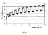
- Fig. 1 shows typical streaming potential change in successive washings of strongly contaminated capillary. It is obvious, that during successive washings streaming potential increases successfully, approaching equilibrium value.
- the invention provides at least two approaches of achieving the objective of increasing reproducibility of electrophoretic analysis of multicomponent solutions by determination of streaming potential.
- capillary washing with electrolyte solution is performed until a limiting magnitude of streaming potential equal to value obtained before making electrophoretic separation of calibration (graduation) solution is achieved, then the scattering of electroosmotic flow rates and consequently retention times of sample components are reduced to a negligible level.
- capillary washing is continued until a streaming potential magnitude somewhat less than limiting one is achieved, and for identification of components corrections are made, determined according to a ratio between the limiting magnitude of streaming potential and magnitude actually obtained in process of washing.
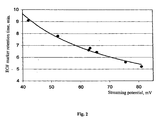
- Fig. 2 shows the change of electroosmotic flow rate, characterized by retention time of EOF marker at various magnitudes of streaming potential U s .
- the determination of streaming potential magnitude during capillary washing, disclosed in the present invention makes it possible to determine the electroosmotic flow rate value at the successive electrophoretic separation of sample components and to increase reproducibility of electrophoretic analysis of multicomponent solutions.
- the disclosed method is applicable in both cases for any type of buffer electrolyte. Both variants are considered below in details.
- Literature or other a priori data may be used to set retention time of known components.
- the mentioned set values of retention time of known components are determined experimentally at the electrophoretic separation of these known components; before the mentioned separation of calibration mixture washing is made with measurement of streaming potential until obtaining threshold value of streaming potential U s 0 .
- the order of value of streaming potential measurement error is chosen to provide high cleanness of capillary and increase reproducibility as acceptable streaming potential deviation value dU s from equilibrium value U eq .
- the specified acceptable deviation value dU s is increased, as a rule, for the purpose of reducing time of washing.
- permissible scatter of sample components retention times is determined, within the limits of which no component identification errors arise while using the set values of retention times of known components, e.g. known components measured at separation of calibration mixture solution.
- the permissible scattering of electroosmotic flow rates is determined. Using dependency between retention time of electroosmotic flow rate marker and streaming potential ( fig. 2 ), it is determined the acceptable streaming potential deviation value dU s from equilibrium value, characterizing clean capillary.
- threshold value of streaming potential selected according to the first case, is corresponding to the first threshold value U s0-1 , obtained at the fifth washing only. At the subsequent washings change of streaming potential is insignificant, therefore the subsequent washings are cancelled.
- the first case of implementation of the invention provides significant growth of reproducibility of electrophoretic separation due to the fact that scattering of electroosmotic flow rates does not exceed the acceptable value.
- the measured retention times of components are compared to set retention times of known components using corrections determined by ratio between the measured limit value of streaming potential U s and the set value of streaming potential U s-set .
- the mentioned corrections are determined using dependency between electroosmotic flow rate and streaming potential.
- the mentioned dependency is determined by calculation method, e.g. using equations (1) and (2), or experimentally, e.g. using EOF markers at different values of streaming potential ( fig. 2 ) or by means for separation of reference solutions with known components at different magnitudes of streaming potential.
- electroosmotic flow rate threshold value U s0 is determined by minimal acceptable rate.
- values of retention times of known components measured at the electrophoretic separation of these known components U s-ca / , determined before electrophoretic separation of calibration mixture of known components with the set streaming potential magnitude U s-set , are selected as the mentioned set values of retention times of known components.
- the second method of calibration is preferable in the event that separation is required of some calibration solutions of known components, while the magnitudes of streaming potential U s-cal , measured before separation of different calibration mixtures, vary.
- the threshold value is sufficiently lower than in the first case, and consequently, is reached considerably earlier.
- the threshold magnitude of streaming potential selected according to the second variant, conforms to the second threshold value U s0-2 , which is reached at the second washing.
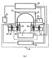
- Fig. 3 shows block diagram of device of electrophoretic analysis of multicomponent solutions, implementing the method of present invention.
- the device contains capillary 1, placed into means for capillary installation 2, vials for electrolyte 3 and 3', vials for sample 4, means for moving said vials 5, made with possibility of immersing capillary ends to said vials.
- Means for creation of electrolyte flow through capillary 6 connected with this vial, where the input capillary 1 end was located (in fig. 3 and 4 left).
- Means for applying voltage between ends of capillary 7 are electrically connected with those vials, where ends of capillary 1 were located.
- Means for streaming potential measurements 9 were made with possibility of electric connection with ends of capillary 1 during washing.
- the device contains detector 8, made with possibility of connection with capillary 1.
- the control and signal processing system 10 is connected with detector 8, means for applying voltage 7, as well as means for creation electrolyte flow through capillary 6 and measurement instrumentation for streaming potential 9.
- Instrument of moving vials 5 is a device for moving vials with solutions, and is made by the method known from the prior art, e.g. using electromechanical drive or power drive.
- Location of selected vial, providing position at the selected capillary end, will be hereinafter referred to as working position of vial.
- Capillary 1 is made as quartz capillary with protection polymeric coating, that is removed at submersible capillary ends and capillary section, connected with detector 8 in case of using optic detector.
- Instruments of installation of capillary 2 are made to provide immersion of capillary 1 ends into vials 3 and 3', being in working position, separation of inner chamber of at least one vial being in working position, from ambient air and connection of the mentioned chamber with instruments of creation electrolyte flow through capillary 6.
- construction of instrument of capillary 2 installation provides location of capillary 1 in flushing channel of liquid thermal medium with the set temperature, providing better stabilization of capillary temperature at electrophoretic separation and decreasing scatter of components retention times due to uncontrolled temperature change.
- Means for generation of electrolyte flow through capillary 6 is a device for creation and maintenance of set pressure difference between the ends of capillary, submerged to vials with solutions it is implemented by method known from the prior art, for example using compressor and pressure difference sensor with possibility of maintenance of set pressure in the mentioned internal chamber.
- Means for applying voltage 7 is a stabilized high voltage source, produced by any known method providing installation of selected high voltage amplitude within the range from zero to maximum. As a rule, maximal amplitude is within the range of 20 - 40 kilovolt.
- the means for applying voltage 7 is made with possibility of switching polarity of high voltage, applied between the ends of a capillary 1.
- Means for applying voltage 7 is equipped with electrodes 11, installed so to submerge their ends to vials 3 and 3', being in working position. As electrodes 11, platinum electrodes are used, as a rule.
- Means for streaming potential measurement 9 includes an instrument for pressure differential measurement 12 between the ends of capillary, made by method known from the prior art, for example as differential amplifier with large input resistance, sufficiently exceeding electric resistance of capillary filled with electrolyte.
- an instrument for pressure differential measurement 12 between the ends of capillary made by method known from the prior art, for example as differential amplifier with large input resistance, sufficiently exceeding electric resistance of capillary filled with electrolyte.
- electric resistance of capillary filled with electrolyte may reach few dozens of M ⁇ , in the preferred embodiment of the invention the input resistance of amplifier is selected within the range of dozens G ⁇ .
- Means for streaming potential measurements 9, electrolyte in vials 3, installed in working position, and capillary 1 filled with electrolyte form an electric measurement circuit.
- Means for streaming potential measurements 9 includes also means for opening streaming potential measurements circuit 13 providing prevention of high voltage effect to the mentioned device for potential difference measurement 12.
- Means for opening electric measurement circuit 13 may be implemented by any known method, e.g. using high voltage relay, electrically connected at least with one of electrodes 11.
- Measurement of opening measurement electric circuit includes measurement electrodes 14 ( Fig.4 ), electrically connected with device of measurement of potential difference 12 measurement instrument of streaming potential 9 and installed in vials filled with buffer electrolyte 3 and 3', which by means for instruments of vials movement 5, is installed in working position at conditioning capillary 1 and measuring streaming potential.
- measurement electrodes 14 electrodes with small residual polarization are used, e.g. chlorine-silver ones, that increases streaming potential measurement accuracy.
- any known detector type for capillary electrophoresis is used, e.g. optical, electrochemical or mass-spectrometric one.
- One skilled in the art can find, that in case of using mass-spectrometric detector at separation, only input capillary end was put into vial with buffer electrolyte, and instruments of measurement streaming potential are implemented taking into account compatibility with input interface of the mass-spectrometric detector.
- control and signal processing system 10 is implemented by method known from the prior art, e.g. using microprocessor controller and personal computer.
- capillary 1 is rinsed with solutions of preliminary washing, selected according to type of substances absorbed earlier, as well as the type of buffer electrolyte used in previous analyses.
- New capillary or capillary not used for a long time are first washed with acid solution, water, alkali solution, and washed by water again. Then conditioning of capillary is made, i.e. rinsing with the same buffer electrolyte, which will be used in the next analysis.
- Washings are made as follows: the selected washing vial with solution of the successive preliminary washing and buffer electrolyte is installed in working position, where the end of capillary 1 is submerged into washing solution of selected vial, and internal chamber of the selected vial is separated from ambient air and pneumatically connected with means for generating electrolyte flow through capillary 6, making excessive pressure, displacing washing solution through capillary 1 to collecting vial (not shown in the figure).
- a streaming potential magnitude is determined.
- vials 3 and 3' with buffer electrolyte are installed in working position opposite input and output ends of capillary 1, where capillary ends are immersed.
- electrodes 11 ends also get to vial of buffer electrolyte.
- Instrument of applying voltage 7 is switched off the electrodes by means for high voltage relay 13, being part of streaming potential measurement means, streaming potential measurement device 9 closing measurement electric circuit, which contains electrodes 11 and buffer electrolyte in both vials and capillary.
- Flow generation apparatus 6 provides zero flow through capillary by creation of zero pressure difference between the ends of capillary.
- streaming potential measurement apparatus measures background potential difference between the ends of capillary, which corresponds in fig.
- Fig. 6 shows variation in time of potential difference magnitudes between the ends of clean capillary at alternate presence and absence of pressure difference between its ends. Sections of low value meanders correspond to background potential difference, and sections of higher potential difference magnitudes correspond to working potential difference. It is obvious that both background and working potential difference are changed in time because of measurement system drift, while streaming potential magnitude is constant. That's why in preferred embodiment of the invention series of successive washings is made to increase streaming potential measurement accuracy; at next washing after the set period of time after its beginning potential difference between capillary ends is reduced up to zero and background potential difference is measured again. The background potential difference change measured that way is used for correction of calculated magnitude of streaming potential, which fact sufficiently reduces errors connected with the mentioned drift.
- a dozing injection of selected sample is made into capillary.
- the vial 4 with selected sample is installed into working position, corresponding to input end of capillary 1 by device moving vials 5.
- a sample one may select either solution of calibration mixture of known components, or solution of unknown composition, components of which are subject to identification and qualitative analysis.
- Injection of sample is made by any known method including, for example, electrokinetic one.
- a sample is injected by flow generation apparatus through capillary 6, making the selected pressure difference between ends of capillary 1 during the selected period of time.
- electrodes 11 are disconnected from measurement circuit and connected to high voltage circuit. Then procedure of electrophoretic separation is made, applying to electrodes 11 selected voltage from the means for voltage generation 7 and sending signals from detector 8 to the control and signal processing system 10.
- detector 8 signal depends on volume of component in sample
- the control and signal processing system 10 registers detector 8 signal changing in time and calculates retention time of each detected sample component equal to time interval between the beginning of electrophoretic separation and the moment of this component detection.
- Retention times measured for different sample components are used for their identification, comparing them to the set retention times of known components, while measured signal amplitudes of detector are used to calculate the concentration of identified components in sample.
- Literature or other data, obtained for other device may be used as set retention time of known components.
- the mentioned set values of retention times of known components are determined at the electrophoretic separation of calibration mixture of these known components, made by the method mentioned above with the same device used for electrophoretic sample separation.
- the measured retention times of components are compared to set retention times of known components using corrections determined by method mentioned above from the ratio between the measured magnitude of streaming potential and the set magnitude of streaming potential.
- model mixture results of analysis of model mixture is shown below, consisting of benzil alcohol, N-phenyl lithium anthranilate and lithium benzoate in 0.001 M solution of sodium tetraborate.
- the prepared solution was used for calibration of experimental model of CE system with streaming potential measurement unit. Calibration was made using a data collection and processing software and recorded as analysis method. All further analyses were made according the same analysis method using the recorded calibration. Retention times for components, averaged over three parallel measurements, and their concentrations (according to production procedure) are shown in table 1. Table 1. Averaged parameters of calibration electropherograms.
- the measured magnitude of streaming potential was 82.5 ⁇ 0.2 mV in average before calibration measurements.
- Typical magnitudes of streaming potential magnitude before analytic measurements were from 67 mV (for experiment No.6) to 80 mV (for 7th experiment).
- table 4 was made, showing improvement of parameters of deviation from calculation values and parameter of reproducibility of results (both for retention times and calculated values of concentration).
- Table 4. Effect of washing of capillary to obtaining the magnitude of streaming potential set magnitude (based on data of tables 2 and 3). Benzil alcohol N-phenyl lithium anthranilate Lithium benzoate in respect to time in respect to concentration in respect to time in respect to concentration in respect to time to time in respect to concentration Deviat.from calculat. 33.9 21.5 12.9 7.0 11.2 1.7 Rel. RMS error 5.4 3.6 5.0 10.1 4.9 5.5
- Table 4 shows that for electrophoretic analysis of multicomponent samples using streaming potential measurement a sufficient improvement is observed of both reproducibility of retention times and accuracy of concentration analysis.
- improvement of reproducibility of retention times for three substances of model solution (Rel. RMS error in time) is from 4.9 to 5.4
- improvement of reproducibility of analysis of concentration of components is from 5.5 to 10.
- accuracy of determination of mean values of retention times and concentrations relative to values for calibration solutions improved even more sufficiently: from 11 to 34 percent for retention times, and from 1.7 to 21.5 percent for concentrations.
- variants not described here in details variant of measurement streaming potential just after electrophoretic separation with determination of appropriate corrections or variant of generation of electrolyte flow through capillary by means for negative pressure difference on output end of capillary, as well as variant of modification of implementation of method in apparatus while using mass-spectrometric detector, but not limited to these examples.
Landscapes
- Health & Medical Sciences (AREA)
- Life Sciences & Earth Sciences (AREA)
- Molecular Biology (AREA)
- Chemical & Material Sciences (AREA)
- Chemical Kinetics & Catalysis (AREA)
- Electrochemistry (AREA)
- Physics & Mathematics (AREA)
- Analytical Chemistry (AREA)
- Biochemistry (AREA)
- General Health & Medical Sciences (AREA)
- General Physics & Mathematics (AREA)
- Immunology (AREA)
- Pathology (AREA)
- Investigating Or Analysing Biological Materials (AREA)
- Investigating Or Analyzing Materials By The Use Of Electric Means (AREA)
- Other Investigation Or Analysis Of Materials By Electrical Means (AREA)
Applications Claiming Priority (2)
| Application Number | Priority Date | Filing Date | Title |
|---|---|---|---|
| RU2006106665/04A RU2300099C1 (ru) | 2006-02-26 | 2006-02-26 | Способ электрофоретического определения состава многокомпонентных растворов и устройство для его осуществления |
| PCT/RU2007/000065 WO2007097660A1 (en) | 2006-02-26 | 2007-02-05 | Method for electrophoretically determine the composition of multicomponent solutions and a device for carrying out said method |
Publications (3)
| Publication Number | Publication Date |
|---|---|
| EP1998170A1 true EP1998170A1 (de) | 2008-12-03 |
| EP1998170A4 EP1998170A4 (de) | 2010-01-20 |
| EP1998170B1 EP1998170B1 (de) | 2014-04-02 |
Family
ID=38310774
Family Applications (1)
| Application Number | Title | Priority Date | Filing Date |
|---|---|---|---|
| EP07747811.3A Active EP1998170B1 (de) | 2006-02-26 | 2007-02-05 | Verfahren zur elektrophoretischen bestimmung der zusammensetzung von lösungen aus mehreren bestandteilen und vorrichtung zur durchführung des verfahrens |
Country Status (8)
| Country | Link |
|---|---|
| US (1) | US8298393B2 (de) |
| EP (1) | EP1998170B1 (de) |
| CN (1) | CN101389952B (de) |
| CA (1) | CA2643361C (de) |
| EA (1) | EA012478B1 (de) |
| RU (1) | RU2300099C1 (de) |
| UA (1) | UA93400C2 (de) |
| WO (1) | WO2007097660A1 (de) |
Families Citing this family (3)
| Publication number | Priority date | Publication date | Assignee | Title |
|---|---|---|---|---|
| JP6126012B2 (ja) * | 2010-12-17 | 2017-05-10 | エフ.ホフマン−ラ ロシュ アーゲーF. Hoffmann−La Roche Aktiengesellschaft | 定量試料分析のための分離および検出処理の複数の装置の自動制御 |
| EP3209410B1 (de) * | 2014-10-22 | 2024-12-25 | IntegenX Inc. | Elektrophoretische kassette und entsprechendes verfahren zur automatisierten vorbereitung, verarbeitung und analyse von proben |
| CN113348362A (zh) | 2019-01-25 | 2021-09-03 | 普诺森公司 | 用于毛细管电泳的可重复使用的盒 |
Family Cites Families (9)
| Publication number | Priority date | Publication date | Assignee | Title |
|---|---|---|---|---|
| SU500502A1 (ru) * | 1973-12-28 | 1976-01-25 | Институт Педиатрии И Детской Хирургии | Способ электрофоретического определени гликозаминогликанов |
| SU1087864A1 (ru) * | 1980-11-03 | 1984-04-23 | Ордена Ленина физико-технический институт им.А.Ф.Иоффе | Устройство дл определени характеристик электропереноса в растворах электролитов |
| SU1567957A1 (ru) * | 1988-02-18 | 1990-05-30 | Латвийский Государственный Университет Им.П.Стучки | Способ определени глюкозы путем изотахофореза |
| SU1597628A1 (ru) * | 1988-11-25 | 1990-10-07 | Предприятие П/Я А-1813 | Электрокинетический преобразователь перепада давлений |
| US5441613A (en) * | 1993-12-03 | 1995-08-15 | Dionex Corporation | Methods and apparatus for real-time monitoring, measurement and control of electroosmotic flow |
| WO1996022151A1 (en) | 1995-01-18 | 1996-07-25 | Dionex Corporation | Methods and apparatus for real-time monitoring, measurement and control of electroosmotic flow |
| JP4152126B2 (ja) | 2002-05-31 | 2008-09-17 | 株式会社日立ハイテクノロジーズ | 電気泳動装置 |
| CN1242262C (zh) * | 2002-08-21 | 2006-02-15 | 中国科学院大连化学物理研究所 | 二维或多维毛细管电泳分离生物大分子的方法 |
| US7211184B2 (en) * | 2004-08-04 | 2007-05-01 | Ast Management Inc. | Capillary electrophoresis devices |
-
2006
- 2006-02-26 RU RU2006106665/04A patent/RU2300099C1/ru active
-
2007
- 2007-02-05 US US12/280,386 patent/US8298393B2/en active Active
- 2007-02-05 EA EA200801831A patent/EA012478B1/ru unknown
- 2007-02-05 CA CA2643361A patent/CA2643361C/en active Active
- 2007-02-05 WO PCT/RU2007/000065 patent/WO2007097660A1/ru not_active Ceased
- 2007-02-05 EP EP07747811.3A patent/EP1998170B1/de active Active
- 2007-02-05 UA UAA200811512A patent/UA93400C2/ru unknown
- 2007-02-05 CN CN2007800067103A patent/CN101389952B/zh active Active
Also Published As
| Publication number | Publication date |
|---|---|
| EA200801831A1 (ru) | 2008-12-30 |
| EP1998170A4 (de) | 2010-01-20 |
| CA2643361C (en) | 2013-10-01 |
| UA93400C2 (ru) | 2011-02-10 |
| EP1998170B1 (de) | 2014-04-02 |
| RU2300099C1 (ru) | 2007-05-27 |
| US8298393B2 (en) | 2012-10-30 |
| US20090038943A1 (en) | 2009-02-12 |
| CN101389952B (zh) | 2012-05-02 |
| CA2643361A1 (en) | 2007-08-30 |
| WO2007097660A1 (en) | 2007-08-30 |
| EA012478B1 (ru) | 2009-10-30 |
| CN101389952A (zh) | 2009-03-18 |
Similar Documents
| Publication | Publication Date | Title |
|---|---|---|
| US5009760A (en) | System for measuring electrokinetic properties and for characterizing electrokinetic separations by monitoring current in electrophoresis | |
| EP0457748B1 (de) | Impulsfeldkapillarelektrophorese | |
| US8063644B2 (en) | Impedance measurement of a pH electrode | |
| JP5550729B2 (ja) | プロトン濃度トポグラフィーならびにその生成方法および生成デバイス | |
| DE69627378D1 (de) | Verfahren zur Bestimmung eines Analyten unter Verwendung einer elektrochemischen Zelle | |
| US5126023A (en) | End-column electrical and electrochemical detector for capillary zone electrophoresis | |
| Verheggen et al. | Simple sampling device for capillary isotachophoresis and capillary zone electrophoresis | |
| EP1998170B1 (de) | Verfahren zur elektrophoretischen bestimmung der zusammensetzung von lösungen aus mehreren bestandteilen und vorrichtung zur durchführung des verfahrens | |
| Horvai et al. | A simple continuous method for calibration and measurement with ion-selective electrodes | |
| Mosher et al. | Dynamic simulator for capillary electrophoresis with in situ calculation of electroosmosis | |
| Williams et al. | Effect of the initial potential ramp on the accuracy of electrophoretic mobilities in capillary electrophoresis | |
| Manabe et al. | Fully automated capillary isotachophoresis of proteins | |
| Corradini et al. | Separation of basic proteins in bare fused-silica capillaries with diethylentriamine phosphate buffer as the background electrolyte solution | |
| US10502709B2 (en) | Electrophoresis device | |
| Ackermans et al. | Isotachophoresis in open systems: problems in quantitative analysis | |
| Catai et al. | Simplex optimization of electrokinetic injection of DNA in capillary electrophoresis using dilute polymer solution | |
| JP2933362B2 (ja) | 電気泳動法における電流の監視により界面動電特性の測定および界面動電分離の特徴づけを行うための改良されたシステム | |
| Klepárník et al. | Determination of the isoelectric points of low and high molecular mass ampholytes by capillary electrophoresis | |
| CN102253103A (zh) | 测定受体配体间结合常数的压力驱动亲和毛细管电泳方法 | |
| JP6361358B2 (ja) | 電気泳動装置 | |
| Gysler et al. | Electromigration peak dispersion of isotachophoretic protein zones during capillary zone electrophoresis | |
| Jung et al. | On-Chip Million-Fold Sample Stacking Using Single-Interface Isotachophoresis | |
| JPH0219900B2 (de) | ||
| JPH0610666B2 (ja) | 細管式等速電気泳動装置 | |
| JP2004077405A (ja) | 酸解離定数測定方法及び測定装置 |
Legal Events
| Date | Code | Title | Description |
|---|---|---|---|
| PUAI | Public reference made under article 153(3) epc to a published international application that has entered the european phase |
Free format text: ORIGINAL CODE: 0009012 |
|
| 17P | Request for examination filed |
Effective date: 20080917 |
|
| AK | Designated contracting states |
Kind code of ref document: A1 Designated state(s): AT BE BG CH CY CZ DE DK EE ES FI FR GB GR HU IE IS IT LI LT LU LV MC NL PL PT RO SE SI SK TR |
|
| A4 | Supplementary search report drawn up and despatched |
Effective date: 20091222 |
|
| 17Q | First examination report despatched |
Effective date: 20100222 |
|
| DAX | Request for extension of the european patent (deleted) | ||
| REG | Reference to a national code |
Ref country code: DE Ref legal event code: R079 Ref document number: 602007035890 Country of ref document: DE Free format text: PREVIOUS MAIN CLASS: G01N0027260000 Ipc: G01N0027447000 |
|
| GRAP | Despatch of communication of intention to grant a patent |
Free format text: ORIGINAL CODE: EPIDOSNIGR1 |
|
| RIC1 | Information provided on ipc code assigned before grant |
Ipc: G01N 27/447 20060101AFI20130823BHEP |
|
| INTG | Intention to grant announced |
Effective date: 20130920 |
|
| GRAS | Grant fee paid |
Free format text: ORIGINAL CODE: EPIDOSNIGR3 |
|
| GRAA | (expected) grant |
Free format text: ORIGINAL CODE: 0009210 |
|
| AK | Designated contracting states |
Kind code of ref document: B1 Designated state(s): AT BE BG CH CY CZ DE DK EE ES FI FR GB GR HU IE IS IT LI LT LU LV MC NL PL PT RO SE SI SK TR |
|
| REG | Reference to a national code |
Ref country code: GB Ref legal event code: FG4D |
|
| REG | Reference to a national code |
Ref country code: AT Ref legal event code: REF Ref document number: 660409 Country of ref document: AT Kind code of ref document: T Effective date: 20140415 Ref country code: CH Ref legal event code: EP |
|
| REG | Reference to a national code |
Ref country code: IE Ref legal event code: FG4D |
|
| REG | Reference to a national code |
Ref country code: DE Ref legal event code: R096 Ref document number: 602007035890 Country of ref document: DE Effective date: 20140515 |
|
| REG | Reference to a national code |
Ref country code: NL Ref legal event code: T3 |
|
| REG | Reference to a national code |
Ref country code: SE Ref legal event code: TRGR |
|
| REG | Reference to a national code |
Ref country code: AT Ref legal event code: MK05 Ref document number: 660409 Country of ref document: AT Kind code of ref document: T Effective date: 20140402 |
|
| REG | Reference to a national code |
Ref country code: LT Ref legal event code: MG4D |
|
| PG25 | Lapsed in a contracting state [announced via postgrant information from national office to epo] |
Ref country code: BG Free format text: LAPSE BECAUSE OF FAILURE TO SUBMIT A TRANSLATION OF THE DESCRIPTION OR TO PAY THE FEE WITHIN THE PRESCRIBED TIME-LIMIT Effective date: 20140702 Ref country code: CZ Free format text: LAPSE BECAUSE OF FAILURE TO SUBMIT A TRANSLATION OF THE DESCRIPTION OR TO PAY THE FEE WITHIN THE PRESCRIBED TIME-LIMIT Effective date: 20140402 Ref country code: FI Free format text: LAPSE BECAUSE OF FAILURE TO SUBMIT A TRANSLATION OF THE DESCRIPTION OR TO PAY THE FEE WITHIN THE PRESCRIBED TIME-LIMIT Effective date: 20140402 Ref country code: CY Free format text: LAPSE BECAUSE OF FAILURE TO SUBMIT A TRANSLATION OF THE DESCRIPTION OR TO PAY THE FEE WITHIN THE PRESCRIBED TIME-LIMIT Effective date: 20140402 Ref country code: IS Free format text: LAPSE BECAUSE OF FAILURE TO SUBMIT A TRANSLATION OF THE DESCRIPTION OR TO PAY THE FEE WITHIN THE PRESCRIBED TIME-LIMIT Effective date: 20140802 Ref country code: GR Free format text: LAPSE BECAUSE OF FAILURE TO SUBMIT A TRANSLATION OF THE DESCRIPTION OR TO PAY THE FEE WITHIN THE PRESCRIBED TIME-LIMIT Effective date: 20140703 Ref country code: LT Free format text: LAPSE BECAUSE OF FAILURE TO SUBMIT A TRANSLATION OF THE DESCRIPTION OR TO PAY THE FEE WITHIN THE PRESCRIBED TIME-LIMIT Effective date: 20140402 |
|
| PG25 | Lapsed in a contracting state [announced via postgrant information from national office to epo] |
Ref country code: ES Free format text: LAPSE BECAUSE OF FAILURE TO SUBMIT A TRANSLATION OF THE DESCRIPTION OR TO PAY THE FEE WITHIN THE PRESCRIBED TIME-LIMIT Effective date: 20140402 Ref country code: AT Free format text: LAPSE BECAUSE OF FAILURE TO SUBMIT A TRANSLATION OF THE DESCRIPTION OR TO PAY THE FEE WITHIN THE PRESCRIBED TIME-LIMIT Effective date: 20140402 Ref country code: LV Free format text: LAPSE BECAUSE OF FAILURE TO SUBMIT A TRANSLATION OF THE DESCRIPTION OR TO PAY THE FEE WITHIN THE PRESCRIBED TIME-LIMIT Effective date: 20140402 Ref country code: PL Free format text: LAPSE BECAUSE OF FAILURE TO SUBMIT A TRANSLATION OF THE DESCRIPTION OR TO PAY THE FEE WITHIN THE PRESCRIBED TIME-LIMIT Effective date: 20140402 |
|
| PG25 | Lapsed in a contracting state [announced via postgrant information from national office to epo] |
Ref country code: PT Free format text: LAPSE BECAUSE OF FAILURE TO SUBMIT A TRANSLATION OF THE DESCRIPTION OR TO PAY THE FEE WITHIN THE PRESCRIBED TIME-LIMIT Effective date: 20140804 |
|
| REG | Reference to a national code |
Ref country code: DE Ref legal event code: R097 Ref document number: 602007035890 Country of ref document: DE |
|
| PG25 | Lapsed in a contracting state [announced via postgrant information from national office to epo] |
Ref country code: BE Free format text: LAPSE BECAUSE OF FAILURE TO SUBMIT A TRANSLATION OF THE DESCRIPTION OR TO PAY THE FEE WITHIN THE PRESCRIBED TIME-LIMIT Effective date: 20140402 Ref country code: RO Free format text: LAPSE BECAUSE OF FAILURE TO SUBMIT A TRANSLATION OF THE DESCRIPTION OR TO PAY THE FEE WITHIN THE PRESCRIBED TIME-LIMIT Effective date: 20140402 Ref country code: DK Free format text: LAPSE BECAUSE OF FAILURE TO SUBMIT A TRANSLATION OF THE DESCRIPTION OR TO PAY THE FEE WITHIN THE PRESCRIBED TIME-LIMIT Effective date: 20140402 Ref country code: SK Free format text: LAPSE BECAUSE OF FAILURE TO SUBMIT A TRANSLATION OF THE DESCRIPTION OR TO PAY THE FEE WITHIN THE PRESCRIBED TIME-LIMIT Effective date: 20140402 Ref country code: EE Free format text: LAPSE BECAUSE OF FAILURE TO SUBMIT A TRANSLATION OF THE DESCRIPTION OR TO PAY THE FEE WITHIN THE PRESCRIBED TIME-LIMIT Effective date: 20140402 |
|
| PLBE | No opposition filed within time limit |
Free format text: ORIGINAL CODE: 0009261 |
|
| STAA | Information on the status of an ep patent application or granted ep patent |
Free format text: STATUS: NO OPPOSITION FILED WITHIN TIME LIMIT |
|
| REG | Reference to a national code |
Ref country code: FR Ref legal event code: PLFP Year of fee payment: 9 |
|
| 26N | No opposition filed |
Effective date: 20150106 |
|
| PG25 | Lapsed in a contracting state [announced via postgrant information from national office to epo] |
Ref country code: IT Free format text: LAPSE BECAUSE OF FAILURE TO SUBMIT A TRANSLATION OF THE DESCRIPTION OR TO PAY THE FEE WITHIN THE PRESCRIBED TIME-LIMIT Effective date: 20140402 |
|
| REG | Reference to a national code |
Ref country code: DE Ref legal event code: R097 Ref document number: 602007035890 Country of ref document: DE Effective date: 20150106 |
|
| PG25 | Lapsed in a contracting state [announced via postgrant information from national office to epo] |
Ref country code: SI Free format text: LAPSE BECAUSE OF FAILURE TO SUBMIT A TRANSLATION OF THE DESCRIPTION OR TO PAY THE FEE WITHIN THE PRESCRIBED TIME-LIMIT Effective date: 20140402 |
|
| PG25 | Lapsed in a contracting state [announced via postgrant information from national office to epo] |
Ref country code: LU Free format text: LAPSE BECAUSE OF FAILURE TO SUBMIT A TRANSLATION OF THE DESCRIPTION OR TO PAY THE FEE WITHIN THE PRESCRIBED TIME-LIMIT Effective date: 20150205 |
|
| REG | Reference to a national code |
Ref country code: CH Ref legal event code: PL |
|
| PG25 | Lapsed in a contracting state [announced via postgrant information from national office to epo] |
Ref country code: LI Free format text: LAPSE BECAUSE OF NON-PAYMENT OF DUE FEES Effective date: 20150228 Ref country code: MC Free format text: LAPSE BECAUSE OF FAILURE TO SUBMIT A TRANSLATION OF THE DESCRIPTION OR TO PAY THE FEE WITHIN THE PRESCRIBED TIME-LIMIT Effective date: 20140402 Ref country code: CH Free format text: LAPSE BECAUSE OF NON-PAYMENT OF DUE FEES Effective date: 20150228 |
|
| REG | Reference to a national code |
Ref country code: IE Ref legal event code: MM4A |
|
| PG25 | Lapsed in a contracting state [announced via postgrant information from national office to epo] |
Ref country code: IE Free format text: LAPSE BECAUSE OF NON-PAYMENT OF DUE FEES Effective date: 20150205 |
|
| REG | Reference to a national code |
Ref country code: FR Ref legal event code: PLFP Year of fee payment: 10 |
|
| PG25 | Lapsed in a contracting state [announced via postgrant information from national office to epo] |
Ref country code: HU Free format text: LAPSE BECAUSE OF FAILURE TO SUBMIT A TRANSLATION OF THE DESCRIPTION OR TO PAY THE FEE WITHIN THE PRESCRIBED TIME-LIMIT; INVALID AB INITIO Effective date: 20070205 |
|
| REG | Reference to a national code |
Ref country code: FR Ref legal event code: PLFP Year of fee payment: 11 |
|
| PG25 | Lapsed in a contracting state [announced via postgrant information from national office to epo] |
Ref country code: TR Free format text: LAPSE BECAUSE OF FAILURE TO SUBMIT A TRANSLATION OF THE DESCRIPTION OR TO PAY THE FEE WITHIN THE PRESCRIBED TIME-LIMIT Effective date: 20140402 |
|
| REG | Reference to a national code |
Ref country code: FR Ref legal event code: PLFP Year of fee payment: 12 |
|
| PGFP | Annual fee paid to national office [announced via postgrant information from national office to epo] |
Ref country code: DE Payment date: 20250212 Year of fee payment: 19 |
|
| PGFP | Annual fee paid to national office [announced via postgrant information from national office to epo] |
Ref country code: SE Payment date: 20250218 Year of fee payment: 19 |
|
| PGFP | Annual fee paid to national office [announced via postgrant information from national office to epo] |
Ref country code: FR Payment date: 20250218 Year of fee payment: 19 |
|
| PGFP | Annual fee paid to national office [announced via postgrant information from national office to epo] |
Ref country code: GB Payment date: 20250218 Year of fee payment: 19 |
|
| PGFP | Annual fee paid to national office [announced via postgrant information from national office to epo] |
Ref country code: NL Payment date: 20260226 Year of fee payment: 20 |