EP1998035A2 - Fluidvektorsteuerung für eine Abgasdüse - Google Patents
Fluidvektorsteuerung für eine Abgasdüse Download PDFInfo
- Publication number
- EP1998035A2 EP1998035A2 EP08251894A EP08251894A EP1998035A2 EP 1998035 A2 EP1998035 A2 EP 1998035A2 EP 08251894 A EP08251894 A EP 08251894A EP 08251894 A EP08251894 A EP 08251894A EP 1998035 A2 EP1998035 A2 EP 1998035A2
- Authority
- EP
- European Patent Office
- Prior art keywords
- vector
- openings
- cover
- cooling air
- assembly
- Prior art date
- Legal status (The legal status is an assumption and is not a legal conclusion. Google has not performed a legal analysis and makes no representation as to the accuracy of the status listed.)
- Granted
Links
Images


Classifications
-
- F—MECHANICAL ENGINEERING; LIGHTING; HEATING; WEAPONS; BLASTING
- F02—COMBUSTION ENGINES; HOT-GAS OR COMBUSTION-PRODUCT ENGINE PLANTS
- F02K—JET-PROPULSION PLANTS
- F02K1/00—Plants characterised by the form or arrangement of the jet pipe or nozzle; Jet pipes or nozzles peculiar thereto
- F02K1/28—Plants characterised by the form or arrangement of the jet pipe or nozzle; Jet pipes or nozzles peculiar thereto using fluid jets to influence the jet flow
-
- F—MECHANICAL ENGINEERING; LIGHTING; HEATING; WEAPONS; BLASTING
- F02—COMBUSTION ENGINES; HOT-GAS OR COMBUSTION-PRODUCT ENGINE PLANTS
- F02K—JET-PROPULSION PLANTS
- F02K1/00—Plants characterised by the form or arrangement of the jet pipe or nozzle; Jet pipes or nozzles peculiar thereto
- F02K1/002—Plants characterised by the form or arrangement of the jet pipe or nozzle; Jet pipes or nozzles peculiar thereto with means to modify the direction of thrust vector
-
- F—MECHANICAL ENGINEERING; LIGHTING; HEATING; WEAPONS; BLASTING
- F02—COMBUSTION ENGINES; HOT-GAS OR COMBUSTION-PRODUCT ENGINE PLANTS
- F02K—JET-PROPULSION PLANTS
- F02K1/00—Plants characterised by the form or arrangement of the jet pipe or nozzle; Jet pipes or nozzles peculiar thereto
- F02K1/38—Introducing air inside the jet
- F02K1/383—Introducing air inside the jet with retractable elements
-
- F—MECHANICAL ENGINEERING; LIGHTING; HEATING; WEAPONS; BLASTING
- F02—COMBUSTION ENGINES; HOT-GAS OR COMBUSTION-PRODUCT ENGINE PLANTS
- F02K—JET-PROPULSION PLANTS
- F02K1/00—Plants characterised by the form or arrangement of the jet pipe or nozzle; Jet pipes or nozzles peculiar thereto
- F02K1/78—Other construction of jet pipes
- F02K1/82—Jet pipe walls, e.g. liners
- F02K1/822—Heat insulating structures or liners, cooling arrangements, e.g. post combustion liners; Infrared radiation suppressors
-
- F—MECHANICAL ENGINEERING; LIGHTING; HEATING; WEAPONS; BLASTING
- F02—COMBUSTION ENGINES; HOT-GAS OR COMBUSTION-PRODUCT ENGINE PLANTS
- F02K—JET-PROPULSION PLANTS
- F02K9/00—Rocket-engine plants, i.e. plants carrying both fuel and oxidant therefor; Control thereof
- F02K9/80—Rocket-engine plants, i.e. plants carrying both fuel and oxidant therefor; Control thereof characterised by thrust or thrust vector control
- F02K9/82—Rocket-engine plants, i.e. plants carrying both fuel and oxidant therefor; Control thereof characterised by thrust or thrust vector control by injection of a secondary fluid into the rocket exhaust gases
Definitions
- This invention relates generally to exhaust nozzles for jet engines. More particularly, this invention relates to fluidic vectoring control for an exhaust nozzle.
- a jet engine includes a compressor providing high-pressure air to a combustor. Fuel and air are mixed within the combustor and ignited, resulting in high-speed exhaust gas that drives the turbine of the jet engine. The exhaust gas exits the jet engine through an exhaust nozzle and generates thrust that propels the aircraft. The exhaust nozzle directs the exhaust gas to optimize thrust produced by the jet engine.
- a layer of cooling air is typically provided to the exhaust nozzle by a plurality of openings within the nozzle liner.
- the layer of cooling air thermally insulates the surface of the exhaust nozzle from the exhaust gas:
- Aircraft movement such as, for example, about the yaw axis, can be accomplished through various methods and combinations of methods including control surfaces, such as a rudder, and directing exhaust gas.
- control surfaces such as a rudder
- directing exhaust gas is via movement of the exhaust nozzle.
- the drawback of movement of the exhaust nozzle is that it requires complicated mechanisms and control systems.
- Another method of directing exhaust gas utilizes high-pressure bleed air directed along different points of the exhaust nozzle.
- Such a device typically requires complicated tubing and channeling in order to communicate air to the desired location in the exhaust nozzle.
- an exhaust nozzle assembly comprising an exhaust passage, an airflow passage for cooling air, a vector opening in communication with the airflow passage and the exhaust passage, and a cover movable for selectively blocking and unblocking a portion of the flow of cooling air from the airflow passage into the exhaust passage.
- the cover may move in a straight line.
- the cover may have a plate opening that selectively unblocks the portion of the flow.
- a method of directing an exhaust gas path comprising the steps of, but not limited to, providing cooling air to an exhaust nozzle, injecting the cooling air into a primary stream of the exhaust nozzle, and adjusting a position of the injecting with respect to the primary stream via a linear movement of a cover plate that blocks a portion of flow of the cooling air.
- the vector opening can have a total flow area that remains substantially constant over an entire range of motion of the cover.
- the cover may move along a centerline of the exhaust nozzle.
- the exhaust passage has a trailing edge and the vector opening may be in proximity to the trailing edge.
- the vector opening can be a plurality of vector openings and the cover may have a plurality of plate openings.
- the size and shape of each of the plurality of vector openings can be equal to the size and shape of each of the plurality of plate openings.
- the plurality of plate openings can be a first set of plate openings and a second set of plate openings, wherein the first set of plate openings is positioned along an upstream portion of the cover and wherein the second set of plate openings is positioned along a downstream portion of the cover.
- the assembly can also have an actuator arm connected to the cover for selectively moving the cover with respect to the vector opening. The injection of the cooling air into the primary stream may provide yaw vectoring.
- the exhaust nozzle assembly of this invention provides thrust vectoring of the primary stream without complex piping and conduits.
- a jet engine assembly 10 includes a propulsion system 12 that intakes air from an inlet 18 mixes it with fuel and generates a primary stream 20 that provides a desired thrust force.
- the primary stream 20 exits through an exhaust nozzle assembly 22 that includes an exhaust passage 24.
- the exhaust passage 24 includes a nozzle throat 14 for accelerating the primary stream 20.
- the exhaust nozzle assembly 22 provides for the fluidic thrust vectoring of the primary stream 20 to enhance aircraft manoeuvrability.
- Exhaust nozzle assembly 22 has a trailing edge 38 and is a converging/diverging nozzle.
- the exhaust passage 24 necks down to a smallest crass-sectional area at the nozzle throat 14, and increases in cross-sectional area from the nozzle throat 14 to the trailing edge 38.
- the particular shape and dimensions of the nozzle assembly 22 can be varied to obtain the performance desired.
- the exhaust nozzle assembly 22 includes an inner duct wall 25 and an outer duct wall 26 spaced apart from each other to define a cooling air passage 40.
- the cooling air passage 40 supplies cooling air 44 (shown in FIGS 3 through 5 ) that can be used to direct the exhaust gas flow path as will be described later in greater detail.
- the inner duct wall 25 can include a plurality of cooling holes (not shown) which when supplied with cooling air 44 via air passage 40 creates an insulating layer of air along the inner duct wall 25.
- the cooling air 44 insulates the inner duct wall 25 from the high temperature of the primary stream 20.
- the volume and rate of cooling air 44 may be fixed for all operating parameters of the propulsion system 12 thereby preventing undesirable fluctuations in propulsion system 12 performance.
- the exhaust nozzle assembly 22 includes one or more vector openings 30 that inject cooling air 44 into the exhaust passage 24.
- there are first and second vector openings 30 but as will be seen in other exemplary embodiments, the present disclosure contemplates the use of other numbers of vector openings.
- the angle of introduction typically is normal to the primary stream 20 but alternative angles are also contemplated by the present disclosure.
- the vector openings 30 are selectively sealed or blocked by a cover plate 32.
- the cover plate 32 is movable with respect to the vector openings 30 to adjust the location that cooling air 44 is injected into the primary stream 20.
- An actuator arm 33 is attached to the cover plate 32 and is actuated by a drive 46 for movement of the cover plate 32. While the exemplary embodiment describes the actuator arm 33 and drive 46 for moving the cover plate 32, the present disclosure contemplates alternative drive mechanisms and methods.
- the cover plate 32 preferably moves along the center line C L of the nozzle to selectively seal or open the vector openings 30.
- the vector openings 30 are positioned near or in proximity to the trailing edge 38 to maximize the yaw vectoring effectiveness of the primary stream 20.
- the cover plate 32 has plate openings 35 that have substantially the same size and shape as the vector openings 30.
- the plate openings 35 are equal in number to the vector openings 30 but are positioned along upstream and downstream portions of the cover plate 32 for reasons which will now be described in greater detail.
- the cover plate 32 can be positioned in a neutral vectoring position so that the amount of vector opening 30, i.e., the flow area, is equal in both the first and second vector openings.
- the neutral vectoring position is accomplished by positioning the plate openings 35 so as to unblock approximately half of each vector opening 30.
- the cover plate As shown in FIG. 4 , as the cover plate is moved downstream along the center line C L as shown by arrow 300, the first vector opening 30 is further opened or unblocked while the second vector opening is closed or blocked.
- the amount of flow area in this first or left vectoring position is substantially equal to the amount of flow area in the neutral vectoring position.
- the cover plate 32 As the cover plate 32 is moving along the centerline C L , the amount of flow area remains substantially constant but the injection position of the cooling air 44 with respect to the gas stream 20 is being changed.
- the second vector opening 30 is further opened or unblocked while the first vector opening is closed or blocked.
- the amount of flow area in this second or right vectoring position is substantially equal to the amount of flow area in the neutral vectoring position, which is also substantially equal to the amount of flow area in the first or left vectoring position.
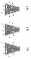
- FIGS. 6 through 8 the effect of changing the position of the injected cooling air 44 by the upstream and downstream movement of the cover plate 32 is shown.
- Vectoring of the primary stream 20 is accomplished by the injection of the cooling air 44 through the vector openings 30 and into the exhaust passage 24.
- the cooling air 44 creates a barrier, or blocked area schematically shown by dashed lines 45 across the trailing edge 38, that restricts the flow of the primary stream 20.
- the resistance to airflow in the blocked areas 45 causes the primary stream to move toward areas of less resistance.
- the primary stream 20 reacts by bending or flowing to the area of least resistance where no barrier to flow exists.
- the cooling air 44 injected into the exhaust passage 24 creates the barrier by generating high-pressure regions 50.
- the high-pressure regions 50 create the resistance to the flow of the primary stream 20.
- the resistance caused by the high-pressure regions 50 does not prevent flow, but provides a resistance to flow of the primary stream that redirects a substantial portion of the primary stream 20.
- the corresponding region of the nozzle does not include cooling air 44 and therefore provides less resistance to flow than the high-pressure region 50.
- the primary stream 20 flows unimpeded through such a region.
- a substantially equal amount of cooling air 44 passes through each of the first and second vector openings 30 on opposing sides of the nozzle. This results in substantially equal amounts of primary stream 20 being redirected toward the center of the exhaust nozzle 22 that in turn results in no directional vectoring of the primary stream 20.
- the cooling air 44 passes through the first or left vector opening 30. This results in the primary stream 20 being redirected toward the opposite side of the exhaust nozzle 22. In the second or right vectoring position, the cooling air 44 passes through the second or right vector opening 30. This results in the primary stream 20 being redirected toward the opposite side of the exhaust nozzle 22.
- the configuration of the vectoring openings 30 with respect to the plate openings 35 allows for redirection of the primary stream 20 while maintaining the same flow area.
- the movement of the cover plate 32 is a small linear movement via the actuator arm 33 that is attached to the cover plate 32 and actuated by the drive 46.
- the small linear movement of the cover plate 32 allows for faster changes in vectoring control and a more responsive control system.
- Cooling air 44 selectively exiting the vector openings 30 generate the high-pressure region 50 to one side of the exhaust nozzle assembly 22 thereby directing a majority of the flow of the primary stream 20 to exit one side of the exhaust nozzle assembly 22. This directional control of the primary stream 20 provides the desired directional thrust utilized to enhance manoeuvrability of the aircraft.
- the exhaust nozzle assembly 122 includes inner duct wall 25 and outer duct wall 26 spaced apart from each other to define cooling air passage 40.
- the exhaust nozzle assembly 122 includes vector openings 130,131 that inject cooling air 44 into the exhaust passage 24.
- the angle of introduction typically is normal to the primary stream 20 but alternative angles are also contemplated by the present disclosure.
- the vector openings 130,131 are selectively sealed or blocked by a cover plate 132.
- the cover plate 132 is movable with respect to the vector openings 130, 131 to adjust the location that cooling air 44 is injected into the primary stream 20.
- An actuator arm 33 is attached to the cover plate 132 and is actuated by a drive 46 for movement of the cover plate 132. While the exemplary embodiment describes the actuator arm 33 and drive 46 for moving the cover plate 132, the present disclosure contemplates alternative drive mechanisms and methods.
- the cover plate 132 preferably moves along the center line C L of the nozzle to selectively seal or open the vector openings 130.
- the vector openings 130 are positioned near the trailing edge 38 to maximize the yaw vectoring effectiveness of the primary stream 20.
- alternative positionings are contemplated by the present disclosure.
- the cover plate 132 has plate openings 135 shaped to maintain the same open area through the vector openings 130.
- the plate openings 135 are positioned along upstream and downstream portions of the cover plate 132.
- the vector openings 130, 131 and have non-rectangular shapes and the plate openings 135 have rectangular shapes but function as described above with respect to the embodiment of FIGS. 1 through 8 to change the position of the injected cooling air 44 and thus direct the primary stream 20.
- the circular shape of the vector openings 130, 131 and rectangular plate openings 135 allow for control of the amount of flow area over the range of cover plate positions as well as control of the rate of change of the re-directing of the primary stream 20.
- the exhaust nozzle assembly 222 includes inner duct wall 25 and outer duct wall 26 spaced apart from each other to define cooling air passage 40.
- the exhaust nozzle assembly 222 includes one or more vector openings 230, 231 that inject cooling air 44 into the exhaust passage 24.
- the angle of introduction typically is normal to the primary stream 20 but alternative angles are also contemplated by the present disclosure.
- the vector openings 230, 231 are selectively sealed or blocked by a cover plate 132.
- the cover plate 132 is movable with respect to the vector openings 230, 231 to adjust the location that cooling air 44 is injected into the primary stream 20.
- An actuator arm 33 is attached to the cover plate 232 and is actuated by a drive 46 for movement of the cover plate 232. While the exemplary embodiment describes the actuator arm 33 and drive 46 for moving the cover plate 232, the present disclosure contemplates alternative drive mechanisms and methods.
- the cover plate 232 preferably moves along the center line C L of the nozzle to selectively seal or open the vector openings 230, 231.
- the vector openings 230, 231 are positioned near the trailing edge 38 to maximize the yaw vectoring effectiveness of the primary stream 20.
- the cover plate 232 has plate openings 235 shaped to maintain the same open area through the vector openings 230, 231.
- the plate openings 235 are positioned along upstream and downstream portions of the cover plate 232.
- the vector openings 230, 231 have a non-rectangular shape and the plate openings 235 have a rectangular shape but function as described above with respect to the embodiment of FIGS. 1 through 8 to change the position of the injected cooling air 44.
- the trapezoidal shape of the vector openings 230, 231 and rectangular plate openings 235 allow for control of the amount of flow area over the range of cover plate positions as well as control of the rate of change of the re-directing of the primary stream 20.
- cover plates 32, 132 and 232 can be used with various shapes and/or curvatures of nozzle liners.
- the shape and orientation of the vector openings 30, 130, 131, 230, 231 and plate openings 35, 135, 235 can be varied to facilitate the vectoring control and directing of the primary stream 20.
- Smaller vector openings 30,130, 131, 230, 231 can be utilized which facilitates their sealing by cover plates 32,132, 232 to prevent unwanted leakage.
- cooling air 44 as described in this invention is utilized to provide thrust vectoring that enhances movement about a yaw axis.
- present disclosure contemplates positioning of the vector openings 30,130,131, 230, 231 within side walls of the exhaust nozzle assemblies 22, 122, 222 to provide for thrust vectoring that would enhance movement about other axes, such as the pitch and roll axis.
- the constant flow of cooling air 44 through the substantially constant flow area regardless of the position of cover plate 32 is desirable because no variation is encountered by the propulsion system 12.
- the exhaust nozzle assemblies 22,122, 222 of the exemplary embodiments described herein provide fluidic thrust vectoring of the primary stream that enhances aircraft manoeuvrability.
Landscapes
- Engineering & Computer Science (AREA)
- Chemical & Material Sciences (AREA)
- Combustion & Propulsion (AREA)
- Mechanical Engineering (AREA)
- General Engineering & Computer Science (AREA)
- Exhaust Silencers (AREA)
- Jet Pumps And Other Pumps (AREA)
Applications Claiming Priority (1)
| Application Number | Priority Date | Filing Date | Title |
|---|---|---|---|
| US11/809,297 US8096104B2 (en) | 2007-05-31 | 2007-05-31 | Fluidic vectoring for exhaust nozzle |
Publications (3)
| Publication Number | Publication Date |
|---|---|
| EP1998035A2 true EP1998035A2 (de) | 2008-12-03 |
| EP1998035A3 EP1998035A3 (de) | 2012-02-08 |
| EP1998035B1 EP1998035B1 (de) | 2013-03-06 |
Family
ID=39687840
Family Applications (1)
| Application Number | Title | Priority Date | Filing Date |
|---|---|---|---|
| EP08251894A Ceased EP1998035B1 (de) | 2007-05-31 | 2008-05-30 | Fluidvektorsteuerung für eine Abgasdüse |
Country Status (2)
| Country | Link |
|---|---|
| US (1) | US8096104B2 (de) |
| EP (1) | EP1998035B1 (de) |
Cited By (3)
| Publication number | Priority date | Publication date | Assignee | Title |
|---|---|---|---|---|
| CN108367253A (zh) * | 2015-11-11 | 2018-08-03 | Ac气控有限责任公司 | 用于至少两个气体的混合和配量的装置 |
| CN110259608A (zh) * | 2019-06-19 | 2019-09-20 | 湖北三江航天红峰控制有限公司 | 一种固体姿轨控发动机喷管堵盖 |
| CN116202774A (zh) * | 2023-04-28 | 2023-06-02 | 中国航发四川燃气涡轮研究院 | 一种高空台矢量试验排气全包容结构 |
Families Citing this family (4)
| Publication number | Priority date | Publication date | Assignee | Title |
|---|---|---|---|---|
| US9745962B2 (en) | 2014-03-10 | 2017-08-29 | X Development Llc | Radiator configuration for a flying wind turbine that passively controls airflow |
| US9964069B2 (en) | 2015-06-29 | 2018-05-08 | United Technologies Corporation | Exhaust nozzle control for a gas turbine engine |
| US10807703B2 (en) * | 2018-07-19 | 2020-10-20 | General Electric Company | Control system for an aircraft |
| CN115807720B (zh) * | 2022-11-22 | 2024-06-21 | 西北工业大学 | 一种基于涡流阀和塞式喷管的变推力膨胀补偿火箭发动机 |
Citations (1)
| Publication number | Priority date | Publication date | Assignee | Title |
|---|---|---|---|---|
| EP1659282A1 (de) | 2004-10-28 | 2006-05-24 | United Technologies Corporation | Schubdüse mit Giermoment |
Family Cites Families (20)
| Publication number | Priority date | Publication date | Assignee | Title |
|---|---|---|---|---|
| US3354645A (en) * | 1966-01-03 | 1967-11-28 | United Aircraft Corp | Method and apparatus for producing a non-axial thrust vector |
| US3749317A (en) * | 1971-03-01 | 1973-07-31 | Mc Donnell Douglas Corp | Thrust vector control system |
| US3794063A (en) * | 1973-01-23 | 1974-02-26 | Thermo King Corp | Refrigerant throttling valve |
| US3859787A (en) * | 1974-02-04 | 1975-01-14 | Gen Motors Corp | Combustion apparatus |
| US5687907A (en) * | 1987-12-18 | 1997-11-18 | United Technologies Corporation | Yaw and pitch thrust vectoring nozzle |
| US5619851A (en) * | 1989-02-08 | 1997-04-15 | United Technologies Corporation | Rocket nozzle for a rocket engine |
| US5427146A (en) * | 1994-06-27 | 1995-06-27 | Bakken; Gary M. | Linearly adjustable fluid damper |
| US5706650A (en) * | 1995-08-09 | 1998-01-13 | United Technologies Corporation | Vectoring nozzle using injected high pressure air |
| IL116668A (en) * | 1996-01-03 | 1998-12-06 | Univ Ramot | Apparatus and method for controlling the motion of a solid body or fluid stream |
| US6112513A (en) * | 1997-08-05 | 2000-09-05 | Lockheed Martin Corporation | Method and apparatus of asymmetric injection at the subsonic portion of a nozzle flow |
| US5996936A (en) * | 1997-09-29 | 1999-12-07 | General Electric Company | Fluidic throat exhaust nozzle |
| US6145299A (en) * | 1998-11-19 | 2000-11-14 | Fasano; Timothy | Rocket engine |
| US6298658B1 (en) * | 1999-12-01 | 2001-10-09 | Williams International Co., L.L.C. | Multi-stable thrust vectoring nozzle |
| US6354074B1 (en) * | 2000-05-24 | 2002-03-12 | Lockheed Martin Corp. | Hybrid injection thrust vector control |
| US6336319B1 (en) * | 2000-05-26 | 2002-01-08 | General Electric Company | Fluidic nozzle control system |
| FR2860045B1 (fr) * | 2003-09-24 | 2006-01-06 | Snecma Moteurs | Systeme de ventilation pour une tuyere d'ejection convergente divergente |
| US7155898B2 (en) * | 2004-04-13 | 2007-01-02 | Aerojet-General Corporation | Thrust vector control system for a plug nozzle rocket engine |
| SE527829C2 (sv) * | 2004-11-05 | 2006-06-13 | Volvo Aero Corp | Utloppsmunstycke till en jetmotor och förfarande för styrning av ett gasflöde från jetmotorn |
| GB0503874D0 (en) * | 2005-02-24 | 2005-04-06 | Rolls Royce Plc | Fluid vectoring nozzle |
| US7509797B2 (en) * | 2005-04-29 | 2009-03-31 | General Electric Company | Thrust vectoring missile turbojet |
-
2007
- 2007-05-31 US US11/809,297 patent/US8096104B2/en active Active
-
2008
- 2008-05-30 EP EP08251894A patent/EP1998035B1/de not_active Ceased
Patent Citations (1)
| Publication number | Priority date | Publication date | Assignee | Title |
|---|---|---|---|---|
| EP1659282A1 (de) | 2004-10-28 | 2006-05-24 | United Technologies Corporation | Schubdüse mit Giermoment |
Cited By (4)
| Publication number | Priority date | Publication date | Assignee | Title |
|---|---|---|---|---|
| CN108367253A (zh) * | 2015-11-11 | 2018-08-03 | Ac气控有限责任公司 | 用于至少两个气体的混合和配量的装置 |
| CN110259608A (zh) * | 2019-06-19 | 2019-09-20 | 湖北三江航天红峰控制有限公司 | 一种固体姿轨控发动机喷管堵盖 |
| CN116202774A (zh) * | 2023-04-28 | 2023-06-02 | 中国航发四川燃气涡轮研究院 | 一种高空台矢量试验排气全包容结构 |
| CN116202774B (zh) * | 2023-04-28 | 2023-08-18 | 中国航发四川燃气涡轮研究院 | 一种高空台矢量试验排气全包容结构 |
Also Published As
| Publication number | Publication date |
|---|---|
| EP1998035A3 (de) | 2012-02-08 |
| US8096104B2 (en) | 2012-01-17 |
| EP1998035B1 (de) | 2013-03-06 |
| US20080295481A1 (en) | 2008-12-04 |
Similar Documents
| Publication | Publication Date | Title |
|---|---|---|
| EP1998035B1 (de) | Fluidvektorsteuerung für eine Abgasdüse | |
| US5706650A (en) | Vectoring nozzle using injected high pressure air | |
| JP5241215B2 (ja) | 航空機エンジンノズルの流体のパッシブ誘導システムおよび方法 | |
| JP4672747B2 (ja) | ロケットノズル及びロケットエンジン燃焼ガス流れの制御方法 | |
| US6634595B2 (en) | Method and apparatus for controlling aircraft inlet air flow | |
| US8371104B2 (en) | System and apparatus for vectoring nozzle exhaust plume from a nozzle | |
| US6679048B1 (en) | Apparatus and method for controlling primary fluid flow using secondary fluid flow injection | |
| KR100417205B1 (ko) | 항공기가스터빈엔진배기노즐의선택적으로냉각가능한발산배기유동한정요소 | |
| US6070407A (en) | Ducted fan gas turbine engine with variable area fan duct nozzle | |
| EP2971739B1 (de) | Kanal einer gasturbine mit zwei reihen von integrierten wärmetauschern | |
| US5833139A (en) | Single variable flap exhaust nozzle | |
| CN103993982A (zh) | 可实现多方向推力矢量控制的双s弯红外隐身喷管结构 | |
| US6000635A (en) | Exhaust nozzle for a turbojet engine | |
| US20100037587A1 (en) | Turbojet Nacelle Equipped With Means For Reducing The Noise Produced By Said Turbojet | |
| US10781756B2 (en) | Active tip clearance control system for gas turbine engine | |
| US7481038B2 (en) | Yaw vectoring for exhaust nozzle | |
| EP3214289B1 (de) | Wärmetauscher für gasturbinentriebwerk | |
| CN88101725A (zh) | 收敛调节片和同轴弧形阀瓣定位方法及连杆系 | |
| US7464535B2 (en) | Rocket motor nozzle throat area control system and method | |
| JP6310302B2 (ja) | ジェットエンジン、飛しょう体及びジェットエンジンの動作方法 | |
| EP1726811A2 (de) | Kühlung der Klappen einer verstellbaren Schubdüse | |
| US8015794B2 (en) | Variable area flow duct employing secondary flows, and method therefor | |
| US6164059A (en) | Multi-expansion ejector nozzle with diverging walls | |
| JPH02286861A (ja) | ターボジェット・エンジン | |
| JP4885301B2 (ja) | ロケットノズル及びロケットエンジン燃焼ガス流れの制御方法 |
Legal Events
| Date | Code | Title | Description |
|---|---|---|---|
| PUAI | Public reference made under article 153(3) epc to a published international application that has entered the european phase |
Free format text: ORIGINAL CODE: 0009012 |
|
| AK | Designated contracting states |
Kind code of ref document: A2 Designated state(s): AT BE BG CH CY CZ DE DK EE ES FI FR GB GR HR HU IE IS IT LI LT LU LV MC MT NL NO PL PT RO SE SI SK TR |
|
| AX | Request for extension of the european patent |
Extension state: AL BA MK RS |
|
| PUAL | Search report despatched |
Free format text: ORIGINAL CODE: 0009013 |
|
| AK | Designated contracting states |
Kind code of ref document: A3 Designated state(s): AT BE BG CH CY CZ DE DK EE ES FI FR GB GR HR HU IE IS IT LI LT LU LV MC MT NL NO PL PT RO SE SI SK TR |
|
| AX | Request for extension of the european patent |
Extension state: AL BA MK RS |
|
| RIC1 | Information provided on ipc code assigned before grant |
Ipc: F02K 9/82 20060101ALI20120103BHEP Ipc: F02K 1/82 20060101ALI20120103BHEP Ipc: F02K 1/28 20060101ALI20120103BHEP Ipc: F02K 1/38 20060101ALI20120103BHEP Ipc: F02K 1/00 20060101AFI20120103BHEP |
|
| 17P | Request for examination filed |
Effective date: 20120803 |
|
| AKX | Designation fees paid |
Designated state(s): DE GB |
|
| GRAP | Despatch of communication of intention to grant a patent |
Free format text: ORIGINAL CODE: EPIDOSNIGR1 |
|
| GRAS | Grant fee paid |
Free format text: ORIGINAL CODE: EPIDOSNIGR3 |
|
| GRAA | (expected) grant |
Free format text: ORIGINAL CODE: 0009210 |
|
| AK | Designated contracting states |
Kind code of ref document: B1 Designated state(s): DE GB |
|
| REG | Reference to a national code |
Ref country code: GB Ref legal event code: FG4D |
|
| REG | Reference to a national code |
Ref country code: DE Ref legal event code: R096 Ref document number: 602008022683 Country of ref document: DE Effective date: 20130425 |
|
| PLBE | No opposition filed within time limit |
Free format text: ORIGINAL CODE: 0009261 |
|
| STAA | Information on the status of an ep patent application or granted ep patent |
Free format text: STATUS: NO OPPOSITION FILED WITHIN TIME LIMIT |
|
| 26N | No opposition filed |
Effective date: 20131209 |
|
| REG | Reference to a national code |
Ref country code: DE Ref legal event code: R097 Ref document number: 602008022683 Country of ref document: DE Effective date: 20131209 |
|
| REG | Reference to a national code |
Ref country code: DE Ref legal event code: R082 Ref document number: 602008022683 Country of ref document: DE Representative=s name: SCHMITT-NILSON SCHRAUD WAIBEL WOHLFROM PATENTA, DE |
|
| REG | Reference to a national code |
Ref country code: DE Ref legal event code: R082 Ref document number: 602008022683 Country of ref document: DE Representative=s name: SCHMITT-NILSON SCHRAUD WAIBEL WOHLFROM PATENTA, DE Ref country code: DE Ref legal event code: R081 Ref document number: 602008022683 Country of ref document: DE Owner name: UNITED TECHNOLOGIES CORP. (N.D.GES.D. STAATES , US Free format text: FORMER OWNER: UNITED TECHNOLOGIES CORP., HARTFORD, CONN., US |
|
| REG | Reference to a national code |
Ref country code: DE Ref legal event code: R081 Ref document number: 602008022683 Country of ref document: DE Owner name: RAYTHEON TECHNOLOGIES CORPORATION (N.D.GES.D.S, US Free format text: FORMER OWNER: UNITED TECHNOLOGIES CORP. (N.D.GES.D. STAATES DELAWARE), FARMINGTON, CONN., US |
|
| P01 | Opt-out of the competence of the unified patent court (upc) registered |
Effective date: 20230519 |
|
| PGFP | Annual fee paid to national office [announced via postgrant information from national office to epo] |
Ref country code: DE Payment date: 20230419 Year of fee payment: 16 |
|
| PGFP | Annual fee paid to national office [announced via postgrant information from national office to epo] |
Ref country code: GB Payment date: 20230420 Year of fee payment: 16 |
|
| REG | Reference to a national code |
Ref country code: DE Ref legal event code: R119 Ref document number: 602008022683 Country of ref document: DE |
|
| GBPC | Gb: european patent ceased through non-payment of renewal fee |
Effective date: 20240530 |
|
| PG25 | Lapsed in a contracting state [announced via postgrant information from national office to epo] |
Ref country code: DE Free format text: LAPSE BECAUSE OF NON-PAYMENT OF DUE FEES Effective date: 20241203 |
|
| PG25 | Lapsed in a contracting state [announced via postgrant information from national office to epo] |
Ref country code: GB Free format text: LAPSE BECAUSE OF NON-PAYMENT OF DUE FEES Effective date: 20240530 |