EP1998010A2 - Bearing arrangement of a turbocharger - Google Patents
Bearing arrangement of a turbocharger Download PDFInfo
- Publication number
- EP1998010A2 EP1998010A2 EP08156340A EP08156340A EP1998010A2 EP 1998010 A2 EP1998010 A2 EP 1998010A2 EP 08156340 A EP08156340 A EP 08156340A EP 08156340 A EP08156340 A EP 08156340A EP 1998010 A2 EP1998010 A2 EP 1998010A2
- Authority
- EP
- European Patent Office
- Prior art keywords
- pin
- bearing
- hub
- bearing bush
- bearing device
- Prior art date
- Legal status (The legal status is an assumption and is not a legal conclusion. Google has not performed a legal analysis and makes no representation as to the accuracy of the status listed.)
- Granted
Links
- 239000010687 lubricating oil Substances 0.000 claims description 5
- 230000001419 dependent effect Effects 0.000 claims description 2
- 239000000853 adhesive Substances 0.000 description 1
- 230000001070 adhesive effect Effects 0.000 description 1
- 238000004519 manufacturing process Methods 0.000 description 1
- 238000011089 mechanical engineering Methods 0.000 description 1
Images

Classifications
-
- F—MECHANICAL ENGINEERING; LIGHTING; HEATING; WEAPONS; BLASTING
- F01—MACHINES OR ENGINES IN GENERAL; ENGINE PLANTS IN GENERAL; STEAM ENGINES
- F01D—NON-POSITIVE DISPLACEMENT MACHINES OR ENGINES, e.g. STEAM TURBINES
- F01D25/00—Component parts, details, or accessories, not provided for in, or of interest apart from, other groups
- F01D25/16—Arrangement of bearings; Supporting or mounting bearings in casings
- F01D25/166—Sliding contact bearing
- F01D25/168—Sliding contact bearing for axial load mainly
-
- F—MECHANICAL ENGINEERING; LIGHTING; HEATING; WEAPONS; BLASTING
- F02—COMBUSTION ENGINES; HOT-GAS OR COMBUSTION-PRODUCT ENGINE PLANTS
- F02C—GAS-TURBINE PLANTS; AIR INTAKES FOR JET-PROPULSION PLANTS; CONTROLLING FUEL SUPPLY IN AIR-BREATHING JET-PROPULSION PLANTS
- F02C6/00—Plural gas-turbine plants; Combinations of gas-turbine plants with other apparatus; Adaptations of gas-turbine plants for special use
- F02C6/04—Gas-turbine plants providing heated or pressurised working fluid for other apparatus, e.g. without mechanical power output
- F02C6/10—Gas-turbine plants providing heated or pressurised working fluid for other apparatus, e.g. without mechanical power output supplying working fluid to a user, e.g. a chemical process, which returns working fluid to a turbine of the plant
- F02C6/12—Turbochargers, i.e. plants for augmenting mechanical power output of internal-combustion piston engines by increase of charge pressure
-
- F—MECHANICAL ENGINEERING; LIGHTING; HEATING; WEAPONS; BLASTING
- F16—ENGINEERING ELEMENTS AND UNITS; GENERAL MEASURES FOR PRODUCING AND MAINTAINING EFFECTIVE FUNCTIONING OF MACHINES OR INSTALLATIONS; THERMAL INSULATION IN GENERAL
- F16C—SHAFTS; FLEXIBLE SHAFTS; ELEMENTS OR CRANKSHAFT MECHANISMS; ROTARY BODIES OTHER THAN GEARING ELEMENTS; BEARINGS
- F16C17/00—Sliding-contact bearings for exclusively rotary movement
- F16C17/10—Sliding-contact bearings for exclusively rotary movement for both radial and axial load
-
- F—MECHANICAL ENGINEERING; LIGHTING; HEATING; WEAPONS; BLASTING
- F16—ENGINEERING ELEMENTS AND UNITS; GENERAL MEASURES FOR PRODUCING AND MAINTAINING EFFECTIVE FUNCTIONING OF MACHINES OR INSTALLATIONS; THERMAL INSULATION IN GENERAL
- F16C—SHAFTS; FLEXIBLE SHAFTS; ELEMENTS OR CRANKSHAFT MECHANISMS; ROTARY BODIES OTHER THAN GEARING ELEMENTS; BEARINGS
- F16C23/00—Bearings for exclusively rotary movement adjustable for aligning or positioning
- F16C23/10—Bearings, parts of which are eccentrically adjustable with respect to each other
-
- F—MECHANICAL ENGINEERING; LIGHTING; HEATING; WEAPONS; BLASTING
- F16—ENGINEERING ELEMENTS AND UNITS; GENERAL MEASURES FOR PRODUCING AND MAINTAINING EFFECTIVE FUNCTIONING OF MACHINES OR INSTALLATIONS; THERMAL INSULATION IN GENERAL
- F16C—SHAFTS; FLEXIBLE SHAFTS; ELEMENTS OR CRANKSHAFT MECHANISMS; ROTARY BODIES OTHER THAN GEARING ELEMENTS; BEARINGS
- F16C25/00—Bearings for exclusively rotary movement adjustable for wear or play
- F16C25/02—Sliding-contact bearings
-
- F—MECHANICAL ENGINEERING; LIGHTING; HEATING; WEAPONS; BLASTING
- F05—INDEXING SCHEMES RELATING TO ENGINES OR PUMPS IN VARIOUS SUBCLASSES OF CLASSES F01-F04
- F05D—INDEXING SCHEME FOR ASPECTS RELATING TO NON-POSITIVE-DISPLACEMENT MACHINES OR ENGINES, GAS-TURBINES OR JET-PROPULSION PLANTS
- F05D2220/00—Application
- F05D2220/40—Application in turbochargers
-
- F—MECHANICAL ENGINEERING; LIGHTING; HEATING; WEAPONS; BLASTING
- F16—ENGINEERING ELEMENTS AND UNITS; GENERAL MEASURES FOR PRODUCING AND MAINTAINING EFFECTIVE FUNCTIONING OF MACHINES OR INSTALLATIONS; THERMAL INSULATION IN GENERAL
- F16C—SHAFTS; FLEXIBLE SHAFTS; ELEMENTS OR CRANKSHAFT MECHANISMS; ROTARY BODIES OTHER THAN GEARING ELEMENTS; BEARINGS
- F16C2360/00—Engines or pumps
- F16C2360/23—Gas turbine engines
- F16C2360/24—Turbochargers
-
- F—MECHANICAL ENGINEERING; LIGHTING; HEATING; WEAPONS; BLASTING
- F16—ENGINEERING ELEMENTS AND UNITS; GENERAL MEASURES FOR PRODUCING AND MAINTAINING EFFECTIVE FUNCTIONING OF MACHINES OR INSTALLATIONS; THERMAL INSULATION IN GENERAL
- F16C—SHAFTS; FLEXIBLE SHAFTS; ELEMENTS OR CRANKSHAFT MECHANISMS; ROTARY BODIES OTHER THAN GEARING ELEMENTS; BEARINGS
- F16C27/00—Elastic or yielding bearings or bearing supports, for exclusively rotary movement
- F16C27/02—Sliding-contact bearings
Definitions
- the invention relates to a bearing device of a turbocharger according to the preamble of patent claim 1.
- Such a storage device is made EP 0 781 908 A2 known.
- the invention is concerned with the problem of creating a possibility for a structurally simple axial adjustment of the bearing bush in a generic bearing device.
- Such an adjustment option is desirable in order to be able to adjust in particular a functionally optimum bearing clearance of the compressor wheel within the surrounding compressor housing with unavoidable manufacturing tolerances of the bearing device including the storage of the compressor in the compressor housing.
- the invention is based on the general idea, the bearing bush with a radially acting on this locking pin To ensure such that an adjustment of the axial position of the bearing bush within the housing hub is possible by simply rotating the pin.
- the locking pin is provided with a securing portion which has a circular cylindrical shape, is arranged eccentrically with respect to the axis of rotation of the pin and engages with this area in a recess of the bearing bush.
- the recess within the bushing must have a clearance in the circumferential direction of the bearing bush with respect to the pin securing area, so that an axial adjustment of the bearing bush is possible.
- the recess may be formed as a closed elongated hole with an orientation of the slot axis in the circumferential direction of the bearing bush or as a running on the circumference of the bearing bush Tangentialnut.
- the pin can be designed as screwed into the hub via a thread.
- the given after an axial adjustment of the bushing rotational position of the pin can be secured by conventional measures to secure a threaded part against rotation.
- Conceivable are the use of a threaded adhesive, a grain of the threaded connection, a non-rotating threaded design or similar, for a Gewindeverwood rejoin usual measures and means.
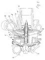
- a turbocharger shaft 4 is mounted in a hub 2 of this housing 1 via a bearing bush 3 within this hub 2. Fixedly connected to the shaft 4 are at one end a turbine wheel 5 and at the other end a compressor wheel 6.
- the bushing 3 has a floating bearing both within the hub 2 and against the shaft 4.
- the floating bearing between the bearing bush 3 and the hub 2 is narrowly limited. This limit is generated by a position-securing pin 7.
- This pin 7 stores in the execution Fig. 1 In a radially on the bearing bush 3 to leading bore 8 within the hub 2. From the bore 8 of the pin 7 engages with a securing portion 9 in a recess 10 of the bearing bush 3 a.
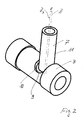
- the securing pin 7 is composed in the axial direction of three areas.
- the securing area 9 is adjoined by a centering area 11, which is followed by a threaded portion 12 forming the end of the pin 7 opposite the securing area 9.
- a slot 13 for attaching a tool for rotating the pin 7 is provided frontally.
- the centering portion 11 is formed as a circular cylindrical portion.
- the centering 11 is assigned a centering or rotation axis Z for the pin 7.
- this centering axis of the securing portion 9 is formed as a circular cylindrical, eccentrically offset portion with an eccentric axis Z s .
- the two axes Z and Z s are around a in Fig. 2 represented eccentric dimension "e" offset from each other.
- the recess 10 within the bearing bush 3 is in the execution after Fig. 1 as a slot formed in the circumferential direction of the bearing bush 3 extending slot axis.
- the pin 7 is in the execution after Fig. 1 . 2 provided with a through hole to introduce through the pin 7 through lubricating oil in the bearing bush 3 can.
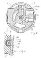
- This locking pin 17 has as well as the backup pin 7 in the axial direction 3 sections, namely a threaded portion 19, a centering portion 20 and a securing portion 21. Functionally, these sections correspond to those of the locking pin 7 in the embodiment according to Fig. 1 , Can be introduced, that is screwed into the hub 2, the locking pin 17 by a provided in the hub 2 lubricating oil supply hole 22.
- the locking pin 17 engages in the lying within the hub 2 end of the supply bore 22 such that around the pin 17 around lubricating oil the bearing bush 3 can be supplied.
- Within the bushing 3 is a radially extending passage 23. This passageway 23 serves to be able to introduce lubricating oil from an annular space between the bearing bush 3 and the hub 2 in an inner, lying between the bearing bush 3 and the shaft 4 annulus.
Landscapes
- Engineering & Computer Science (AREA)
- General Engineering & Computer Science (AREA)
- Mechanical Engineering (AREA)
- Chemical & Material Sciences (AREA)
- Chemical Kinetics & Catalysis (AREA)
- General Chemical & Material Sciences (AREA)
- Combustion & Propulsion (AREA)
- Supercharger (AREA)
Abstract
Description
Die Erfindung betrifft eine Lagereinrichtung eines Turboladers nach dem Oberbegriff des Patentanspruchs 1.The invention relates to a bearing device of a turbocharger according to the preamble of
Eine solche Lagereinrichtung ist aus
Die Erfindung beschäftigt sich mit dem Problem, bei einer gattungsgemäßen Lagereinrichtung eine Möglichkeit für eine konstruktiv einfache axiale Justierung der Lagerbuchse zu schaffen. Eine solche Justiermöglichkeit ist erwünscht, um insbesondere ein funktionsoptimales Lagerspiel des Verdichterrades innerhalb des dieses umgebenden Verdichtergehäuses bei unvermeidbaren Fertigungstoleranzen der Lagereinrichtung einschließlich der Lagerung des Verdichterrades in dem Verdichtergehäuse einstellen zu können.The invention is concerned with the problem of creating a possibility for a structurally simple axial adjustment of the bearing bush in a generic bearing device. Such an adjustment option is desirable in order to be able to adjust in particular a functionally optimum bearing clearance of the compressor wheel within the surrounding compressor housing with unavoidable manufacturing tolerances of the bearing device including the storage of the compressor in the compressor housing.
Zweckmäßige und vorteilhafte Ausgestaltungen der Erfindung sind Gegenstand der Unteransprüche.Advantageous and advantageous embodiments of the invention are the subject of the dependent claims.
Die Erfindung beruht auf dem allgemeinen Gedanken, die Lagerbuchse mit einem radial an dieser angreifenden Sicherungsstift derart lagezusichern, dass durch ein einfaches Verdrehen des Stiftes eine Justierung der axialen Position der Lagerungsbuchse innerhalb der Gehäusenabe möglich ist. Ermöglicht wird dies dadurch, dass der Sicherungsstift mit einem Sicherungsbereich versehen ist, der kreiszylindrische Form besitzt, gegenüber der Drehachse des Stiftes exzentrisch angeordnet ist und mit diesem Bereich in eine Ausnehmung der Lagerbuchse eingreift. Die Ausnehmung innerhalb der Lagerbuchse muss in Umfangsrichtung der Lagerbuchse ein Spiel gegenüber dem Stiftsicherungsbereich aufweisen, damit eine Axialverstellung der Lagerbuchse möglich ist. Die Ausnehmung kann als eine geschlossene Langlochbohrung mit einer Ausrichtung der Langlochachse in Umfangsrichtung der Lagerbuchse ausgebildet sein oder als eine auf dem Umfang der Lagerbuchse verlaufende Tangentialnut.The invention is based on the general idea, the bearing bush with a radially acting on this locking pin To ensure such that an adjustment of the axial position of the bearing bush within the housing hub is possible by simply rotating the pin. This is made possible by the fact that the locking pin is provided with a securing portion which has a circular cylindrical shape, is arranged eccentrically with respect to the axis of rotation of the pin and engages with this area in a recess of the bearing bush. The recess within the bushing must have a clearance in the circumferential direction of the bearing bush with respect to the pin securing area, so that an axial adjustment of the bearing bush is possible. The recess may be formed as a closed elongated hole with an orientation of the slot axis in the circumferential direction of the bearing bush or as a running on the circumference of the bearing bush Tangentialnut.
Der Stift kann als in die Nabe über ein Gewinde einschraubbar ausgebildet sein. Die nach einer Axialjustierung der Lagerbuchse gegebene Drehposition des Stiftes kann durch übliche Maßnahmen zur Sicherung eines Gewindeteiles gegen Drehen gesichert werden. Denkbar sind der Einsatz eines Gewindeklebstoffes, eine Körnung der Gewindeverbindung, eine verdrehgesicherte Gewindeausführung oder ähnliche, für eine Gewindeverdrehsicherung übliche Maßnahmen und Mittel.The pin can be designed as screwed into the hub via a thread. The given after an axial adjustment of the bushing rotational position of the pin can be secured by conventional measures to secure a threaded part against rotation. Conceivable are the use of a threaded adhesive, a grain of the threaded connection, a non-rotating threaded design or similar, for a Gewindeverdrehsicherung usual measures and means.
Vorteilhafte, nachstehend näher erläuterte Ausführungsbeispiele sind in der Zeichnung dargestellt.Advantageous, explained in more detail below embodiments are shown in the drawing.
In dieser zeigen
- Fig. 1
- einen Schnitt durch den Lagerbereich einer Turboladerwelle mit an deren axialen Enden einenends einem angebundenen Turbinenrad und einem anderenends angebundenen Verdichterrad und einem radial in eine umfangsmäßig geschlossene Ausnehmung der Lagerbuchse eingreifenden Sicherungsstift,
- Fig. 2
- eine perspektivische Darstellung einer Lagerbuchse mit einem Langloch und einem in dieses eingreifenden Sicherungs-Stift,
- Fig. 3
- einen Schnitt durch ein Turboladergehäuse mit einem an dem Umfang der Lagerbuchse angreifenden Sicherungsstift in einer ersten Ausführung,
- Fig. 4
- eine perspektivische Ansicht einer Lagerbuchse aus der Einrichtung nach
Fig. 3 mit einem in eine an dem Umfang der Lagerbuchse vorgesehene Tangentialnut eingreifenden Sicherungsstift, - Fig. 5
- eine zweite Ausführungsform der Einrichtung nach
Fig. 3 , - Fig. 6
- einen vergrößerten Ausschnitt aus der Einrichtung nach
Fig. 5 .
- Fig. 1
- 3 shows a section through the bearing area of a turbocharger shaft with at its axial ends at one end a connected turbine wheel and another compressor wheel connected at the other end and a locking pin engaging radially in a circumferentially closed recess of the bearing bush,
- Fig. 2
- a perspective view of a bearing bush with a slot and a engaging in this safety pin,
- Fig. 3
- a section through a turbocharger housing with an engaging on the circumference of the bearing bush locking pin in a first embodiment,
- Fig. 4
- a perspective view of a bearing bush from the device according to
Fig. 3 with a locking pin engaging in a tangential groove provided on the circumference of the bearing bush, - Fig. 5
- a second embodiment of the device according to
Fig. 3 . - Fig. 6
- an enlarged section of the device after
Fig. 5 ,
In einem Turboladergehäuse 1 ist in einer Nabe 2 dieses Gehäuses 1 über eine Lagerbuchse 3 innerhalb dieser Nabe 2 eine Turbolader-Welle 4 gelagert. Fest mit der Welle 4 verbunden sind einenends ein Turbinenrad 5 und anderenends ein Verdichterrad 6.In a
Die Lagerbuchse 3 weist eine schwimmende Lagerung sowohl innerhalb der Nabe 2 als auch gegenüber der Welle 4 auf. Dabei ist die schwimmende Lagerung zwischen der Lagerbuchse 3 und der Nabe 2 eng begrenzt. Diese Begrenzung wird erzeugt durch einen Lagesicherungs-Stift 7. Dieser Stift 7 lagert bei der Ausführung nach
Der Sicherungs-Stift 7 setzt sich in axialer Richtung aus drei Bereichen zusammen. An den Sicherungsbereich 9 schließt sich ein Zentrierbereich 11 an, dem ein, das dem Sicherungsbereich 9 entgegengesetzte Ende des Stiftes 7 bildender Gewindeabschnitt 12 folgt. In dem Gewindeabschnitt 12 ist stirnseitig ein Schlitz 13 für das Ansetzen eines Werkzeuges zum Verdrehen des Stiftes 7 vorgesehen. Der Zentrierbereich 11 ist als ein kreiszylindrischer Abschnitt ausgebildet. Dem Zentrierbereich 11 ist eine Zentrier- beziehungsweise Drehachse Z für den Stift 7 zugeordnet. Gegenüber dieser Zentrierachse ist der Sicherungsbereich 9 als ein kreiszylindrischer, exzentrisch versetzter Abschnitt mit einer ExzenterAchse Zs ausgebildet. Die beiden Achsen Z und Zs sind um ein in
Der Stift 7 ist bei der Ausführung nach
Durch ein Verdrehen des Stiftes 7 um die Zentrierachse Z kann über dessen exzentrischem Sicherungsbereich 9 eine axiale Verstellung, das heißt Justierung der Lagerbuchse 3 innerhalb der Nabe 2 des Turbolader-Gehäuses 1 erreicht werden. Nach erfolgter Justierung wird das Gewinde zwischen dem Stift 7 und der Nabe 2 in einer im Maschinenbau üblichen Weise verdrehgesichert. Die Ausführung der Lagereinrichtung nach
Dieser Sicherungsstift 17 besitzt ebenso wie der Sicherungs-stift 7 in axialer Richtung 3 Abschnitte, nämlich einen Gewindeabschnitt 19, einen Zentrierabschnitt 20 sowie einen Sicherungsabschnitt 21. Funktionell entsprechen diese Abschnitte denjenigen des Sicherungsstiftes 7 bei der Ausführung nach
Die Ausführung nach
Alle in der Beschreibung und in den nachfolgenden Ansprüchen dargestellten Merkmale können sowohl einzeln als auch in beliebiger Form miteinander kombiniert erfindungswesentlich sein.All features described in the description and in the following claims can be essential to the invention, both individually and in any desired form.
Claims (7)
dadurch gekennzeichnet,
dass die Ausnehmung (10) als ein umfangsmäßig geschlossenes Langloch ausgebildet ist.Bearing device according to claim 1,
characterized,
that the recess (10) is formed as a circumferentially closed slot.
dadurch gekennzeichnet,
dass die Ausnehmung (10) als eine auf dem Umfang der Lagerbuchse (3) liegende Tangentialnut (18) ausgebildet ist.Bearing device according to claim 1,
characterized,
is formed that the recess (10) lying as a on the periphery of the bearing bush (3) tangential groove (18).
dadurch gekennzeichnet,
dass der Stift (7) eine Durchgangsbohrung besitzt.Bearing device according to one of the preceding claims,
characterized,
that the pin (7) has a through hole.
dadurch gekennzeichnet,
dass der Stift (7) in die Nabe (2) eingeschraubt ist.Bearing device according to one of the preceding claims,
characterized,
that the pin (7) is screwed into the hub (2).
dadurch gekennzeichnet,
dass der Stift (7) einen kreiszylindrischen Zentrierabschnitt (11, 20) zu einer zentrischen Lagerung innerhalb der Nabe (2) besitzt.Bearing device according to one of the preceding claims,
characterized,
in that the pin (7) has a circular-cylindrical centering section (11, 20) for a centric bearing within the hub (2).
dadurch gekennzeichnet,
dass der Stift (7) in einem Nabenbereich liegt, in dem er durch eine dort vorgesehene Bohrung (22) zur Schmierölversorgung der Lagerbuchse (3) einführ- und durch ein Werkzeug verdrehbar ist.Bearing device according to claim 3 or 5 or 6, as far as these claims are dependent on claim 3,
characterized,
in that the pin (7) lies in a hub region, in which it can be introduced through a bore (22) provided there for supplying lubricating oil to the bearing bush (3) and can be rotated by a tool.
Applications Claiming Priority (1)
| Application Number | Priority Date | Filing Date | Title |
|---|---|---|---|
| DE102007025130A DE102007025130A1 (en) | 2007-05-30 | 2007-05-30 | Bearing device of a turbocharger |
Publications (3)
| Publication Number | Publication Date |
|---|---|
| EP1998010A2 true EP1998010A2 (en) | 2008-12-03 |
| EP1998010A3 EP1998010A3 (en) | 2010-07-21 |
| EP1998010B1 EP1998010B1 (en) | 2011-07-13 |
Family
ID=39760681
Family Applications (1)
| Application Number | Title | Priority Date | Filing Date |
|---|---|---|---|
| EP08156340A Active EP1998010B1 (en) | 2007-05-30 | 2008-05-16 | Bearing arrangement of a turbocharger |
Country Status (2)
| Country | Link |
|---|---|
| EP (1) | EP1998010B1 (en) |
| DE (1) | DE102007025130A1 (en) |
Cited By (3)
| Publication number | Priority date | Publication date | Assignee | Title |
|---|---|---|---|---|
| CN108223136A (en) * | 2016-12-22 | 2018-06-29 | 博世马勒涡轮系统有限两合公司 | Booster |
| CN108223132A (en) * | 2016-12-12 | 2018-06-29 | 霍尼韦尔国际公司 | Turbocharger assembly |
| US10138781B2 (en) | 2016-09-01 | 2018-11-27 | Ford Global Technologies, Llc | Method and system to improve cold-start catalyst light-off |
Families Citing this family (1)
| Publication number | Priority date | Publication date | Assignee | Title |
|---|---|---|---|---|
| DE102012202468B3 (en) | 2012-02-17 | 2013-07-04 | Siemens Aktiengesellschaft | turbomachinery |
Citations (1)
| Publication number | Priority date | Publication date | Assignee | Title |
|---|---|---|---|---|
| EP0781908A2 (en) | 1995-12-26 | 1997-07-02 | Ishikawajima-Harima Heavy Industries Co., Ltd. | Turbocharger construction |
Family Cites Families (4)
| Publication number | Priority date | Publication date | Assignee | Title |
|---|---|---|---|---|
| CH407665A (en) * | 1964-04-06 | 1966-02-15 | Buechi Alfred Johann Dipl Masc | Storage of centrifugal machine rotors |
| US3811741A (en) * | 1972-12-26 | 1974-05-21 | Garrett Corp | Bearing |
| DE3601082A1 (en) * | 1986-01-16 | 1987-07-23 | Kuehnle Kopp Kausch Ag | EXHAUST TURBOCHARGER |
| DE4230037A1 (en) * | 1991-09-09 | 1993-03-11 | Aisin Seiki | CENTRIFUGAL RECHARGE BLOWER |
-
2007
- 2007-05-30 DE DE102007025130A patent/DE102007025130A1/en not_active Withdrawn
-
2008
- 2008-05-16 EP EP08156340A patent/EP1998010B1/en active Active
Patent Citations (1)
| Publication number | Priority date | Publication date | Assignee | Title |
|---|---|---|---|---|
| EP0781908A2 (en) | 1995-12-26 | 1997-07-02 | Ishikawajima-Harima Heavy Industries Co., Ltd. | Turbocharger construction |
Cited By (4)
| Publication number | Priority date | Publication date | Assignee | Title |
|---|---|---|---|---|
| US10138781B2 (en) | 2016-09-01 | 2018-11-27 | Ford Global Technologies, Llc | Method and system to improve cold-start catalyst light-off |
| CN108223132A (en) * | 2016-12-12 | 2018-06-29 | 霍尼韦尔国际公司 | Turbocharger assembly |
| CN108223136A (en) * | 2016-12-22 | 2018-06-29 | 博世马勒涡轮系统有限两合公司 | Booster |
| CN108223136B (en) * | 2016-12-22 | 2021-06-11 | 博马科技有限责任公司 | Pressure booster |
Also Published As
| Publication number | Publication date |
|---|---|
| EP1998010A3 (en) | 2010-07-21 |
| DE102007025130A1 (en) | 2008-12-04 |
| EP1998010B1 (en) | 2011-07-13 |
Similar Documents
| Publication | Publication Date | Title |
|---|---|---|
| DE60311725T2 (en) | Arrangement of a compressor impeller | |
| DE102008058618B4 (en) | Modular system for exhaust gas turbochargers | |
| WO2011057949A1 (en) | Axial bearing arrangement for a shaft of a turbocharger | |
| EP3524781B1 (en) | Connecting device for an adjustable vane of a gas turbine | |
| DE102010063703A1 (en) | Phaser | |
| EP2683941B1 (en) | Planetary transmission for wind turbine | |
| EP3284964A1 (en) | Bearing device of an exhaust turbocharger | |
| EP2744988A1 (en) | Camshaft, especially for motor vehicle engines | |
| EP1998010B1 (en) | Bearing arrangement of a turbocharger | |
| EP2233747B1 (en) | Multi stage motor pump unit | |
| EP1092081A1 (en) | Rotor for a turbomachine | |
| DE102008059598A1 (en) | Exhaust gas turbocharger for internal-combustion engine of motor vehicle, has bearing arrangement with cone bearings e.g. hydrodynamic sliding bearings that are axially spaced from each other and have opposite tapers | |
| DE102013018775A1 (en) | Lantern-transmission device | |
| WO2012004336A2 (en) | Compressor | |
| DE102008051142B4 (en) | Camshaft adjuster | |
| EP3203035A1 (en) | Blade system for a flow machine | |
| DE102005032644B4 (en) | Gear pump, in particular gear oil pump for vehicles | |
| DE19961567B4 (en) | Hydraulic device for continuously variable camshaft adjustment | |
| EP1375953A2 (en) | Multi-part brake disc | |
| EP1792806B1 (en) | Steering angle sensor | |
| EP2816198B1 (en) | Guide vane assembly, guide vane and method for mounting a guide vane | |
| EP2758678A1 (en) | Connecting rod | |
| DE102010035572A1 (en) | Gear motor i.e. servomotor, for use in actuator for e.g. exhaust gas turbocharger of internal combustion engine of motor car, has gear rotatably arranged around central axis, and output element connected with gear in torque-proof manner | |
| WO2020109144A1 (en) | Drive device for a motor vehicle having a drive unit | |
| EP4031785B1 (en) | Slide ring seal assembly which can be axially mounted |
Legal Events
| Date | Code | Title | Description |
|---|---|---|---|
| PUAI | Public reference made under article 153(3) epc to a published international application that has entered the european phase |
Free format text: ORIGINAL CODE: 0009012 |
|
| AK | Designated contracting states |
Kind code of ref document: A2 Designated state(s): AT BE BG CH CY CZ DE DK EE ES FI FR GB GR HR HU IE IS IT LI LT LU LV MC MT NL NO PL PT RO SE SI SK TR |
|
| AX | Request for extension of the european patent |
Extension state: AL BA MK RS |
|
| PUAL | Search report despatched |
Free format text: ORIGINAL CODE: 0009013 |
|
| AK | Designated contracting states |
Kind code of ref document: A3 Designated state(s): AT BE BG CH CY CZ DE DK EE ES FI FR GB GR HR HU IE IS IT LI LT LU LV MC MT NL NO PL PT RO SE SI SK TR |
|
| AX | Request for extension of the european patent |
Extension state: AL BA MK RS |
|
| 17P | Request for examination filed |
Effective date: 20101123 |
|
| GRAP | Despatch of communication of intention to grant a patent |
Free format text: ORIGINAL CODE: EPIDOSNIGR1 |
|
| RIC1 | Information provided on ipc code assigned before grant |
Ipc: F01D 25/16 20060101AFI20110111BHEP |
|
| GRAC | Information related to communication of intention to grant a patent modified |
Free format text: ORIGINAL CODE: EPIDOSCIGR1 |
|
| AKX | Designation fees paid |
Designated state(s): DE FR GB |
|
| GRAS | Grant fee paid |
Free format text: ORIGINAL CODE: EPIDOSNIGR3 |
|
| GRAA | (expected) grant |
Free format text: ORIGINAL CODE: 0009210 |
|
| AK | Designated contracting states |
Kind code of ref document: B1 Designated state(s): DE FR GB |
|
| REG | Reference to a national code |
Ref country code: GB Ref legal event code: FG4D Free format text: NOT ENGLISH |
|
| REG | Reference to a national code |
Ref country code: DE Ref legal event code: R096 Ref document number: 502008004182 Country of ref document: DE Effective date: 20110908 |
|
| PLBE | No opposition filed within time limit |
Free format text: ORIGINAL CODE: 0009261 |
|
| STAA | Information on the status of an ep patent application or granted ep patent |
Free format text: STATUS: NO OPPOSITION FILED WITHIN TIME LIMIT |
|
| 26N | No opposition filed |
Effective date: 20120416 |
|
| REG | Reference to a national code |
Ref country code: DE Ref legal event code: R097 Ref document number: 502008004182 Country of ref document: DE Effective date: 20120416 |
|
| REG | Reference to a national code |
Ref country code: FR Ref legal event code: PLFP Year of fee payment: 9 |
|
| REG | Reference to a national code |
Ref country code: FR Ref legal event code: PLFP Year of fee payment: 10 |
|
| REG | Reference to a national code |
Ref country code: FR Ref legal event code: PLFP Year of fee payment: 11 |
|
| REG | Reference to a national code |
Ref country code: DE Ref legal event code: R082 Ref document number: 502008004182 Country of ref document: DE Representative=s name: BRP RENAUD UND PARTNER MBB RECHTSANWAELTE PATE, DE Ref country code: DE Ref legal event code: R081 Ref document number: 502008004182 Country of ref document: DE Owner name: BMTS TECHNOLOGY GMBH & CO. KG, DE Free format text: FORMER OWNER: BOSCH MAHLE TURBO SYSTEMS GMBH & CO. KG, 70376 STUTTGART, DE |
|
| REG | Reference to a national code |
Ref country code: DE Ref legal event code: R082 Ref document number: 502008004182 Country of ref document: DE |
|
| PGFP | Annual fee paid to national office [announced via postgrant information from national office to epo] |
Ref country code: GB Payment date: 20240521 Year of fee payment: 17 |
|
| PGFP | Annual fee paid to national office [announced via postgrant information from national office to epo] |
Ref country code: DE Payment date: 20240521 Year of fee payment: 17 |
|
| PGFP | Annual fee paid to national office [announced via postgrant information from national office to epo] |
Ref country code: FR Payment date: 20240529 Year of fee payment: 17 |