EP1997929A2 - Closed pore ceramic composite article - Google Patents
Closed pore ceramic composite article Download PDFInfo
- Publication number
- EP1997929A2 EP1997929A2 EP20080250952 EP08250952A EP1997929A2 EP 1997929 A2 EP1997929 A2 EP 1997929A2 EP 20080250952 EP20080250952 EP 20080250952 EP 08250952 A EP08250952 A EP 08250952A EP 1997929 A2 EP1997929 A2 EP 1997929A2
- Authority
- EP
- European Patent Office
- Prior art keywords
- recited
- thermal barrier
- ceramic
- closed pores
- composite article
- Prior art date
- Legal status (The legal status is an assumption and is not a legal conclusion. Google has not performed a legal analysis and makes no representation as to the accuracy of the status listed.)
- Granted
Links
Images

Classifications
-
- C—CHEMISTRY; METALLURGY
- C04—CEMENTS; CONCRETE; ARTIFICIAL STONE; CERAMICS; REFRACTORIES
- C04B—LIME, MAGNESIA; SLAG; CEMENTS; COMPOSITIONS THEREOF, e.g. MORTARS, CONCRETE OR LIKE BUILDING MATERIALS; ARTIFICIAL STONE; CERAMICS; REFRACTORIES; TREATMENT OF NATURAL STONE
- C04B38/00—Porous mortars, concrete, artificial stone or ceramic ware; Preparation thereof
- C04B38/0051—Porous mortars, concrete, artificial stone or ceramic ware; Preparation thereof characterised by the pore size, pore shape or kind of porosity
- C04B38/0061—Porous mortars, concrete, artificial stone or ceramic ware; Preparation thereof characterised by the pore size, pore shape or kind of porosity closed porosity
-
- B—PERFORMING OPERATIONS; TRANSPORTING
- B28—WORKING CEMENT, CLAY, OR STONE
- B28B—SHAPING CLAY OR OTHER CERAMIC COMPOSITIONS; SHAPING SLAG; SHAPING MIXTURES CONTAINING CEMENTITIOUS MATERIAL, e.g. PLASTER
- B28B3/00—Producing shaped articles from the material by using presses; Presses specially adapted therefor
-
- C—CHEMISTRY; METALLURGY
- C04—CEMENTS; CONCRETE; ARTIFICIAL STONE; CERAMICS; REFRACTORIES
- C04B—LIME, MAGNESIA; SLAG; CEMENTS; COMPOSITIONS THEREOF, e.g. MORTARS, CONCRETE OR LIKE BUILDING MATERIALS; ARTIFICIAL STONE; CERAMICS; REFRACTORIES; TREATMENT OF NATURAL STONE
- C04B35/00—Shaped ceramic products characterised by their composition; Ceramics compositions; Processing powders of inorganic compounds preparatory to the manufacturing of ceramic products
- C04B35/622—Forming processes; Processing powders of inorganic compounds preparatory to the manufacturing of ceramic products
- C04B35/626—Preparing or treating the powders individually or as batches ; preparing or treating macroscopic reinforcing agents for ceramic products, e.g. fibres; mechanical aspects section B
- C04B35/62605—Treating the starting powders individually or as mixtures
- C04B35/62695—Granulation or pelletising
-
- C—CHEMISTRY; METALLURGY
- C04—CEMENTS; CONCRETE; ARTIFICIAL STONE; CERAMICS; REFRACTORIES
- C04B—LIME, MAGNESIA; SLAG; CEMENTS; COMPOSITIONS THEREOF, e.g. MORTARS, CONCRETE OR LIKE BUILDING MATERIALS; ARTIFICIAL STONE; CERAMICS; REFRACTORIES; TREATMENT OF NATURAL STONE
- C04B35/00—Shaped ceramic products characterised by their composition; Ceramics compositions; Processing powders of inorganic compounds preparatory to the manufacturing of ceramic products
- C04B35/622—Forming processes; Processing powders of inorganic compounds preparatory to the manufacturing of ceramic products
- C04B35/64—Burning or sintering processes
-
- C—CHEMISTRY; METALLURGY
- C23—COATING METALLIC MATERIAL; COATING MATERIAL WITH METALLIC MATERIAL; CHEMICAL SURFACE TREATMENT; DIFFUSION TREATMENT OF METALLIC MATERIAL; COATING BY VACUUM EVAPORATION, BY SPUTTERING, BY ION IMPLANTATION OR BY CHEMICAL VAPOUR DEPOSITION, IN GENERAL; INHIBITING CORROSION OF METALLIC MATERIAL OR INCRUSTATION IN GENERAL
- C23C—COATING METALLIC MATERIAL; COATING MATERIAL WITH METALLIC MATERIAL; SURFACE TREATMENT OF METALLIC MATERIAL BY DIFFUSION INTO THE SURFACE, BY CHEMICAL CONVERSION OR SUBSTITUTION; COATING BY VACUUM EVAPORATION, BY SPUTTERING, BY ION IMPLANTATION OR BY CHEMICAL VAPOUR DEPOSITION, IN GENERAL
- C23C28/00—Coating for obtaining at least two superposed coatings either by methods not provided for in a single one of groups C23C2/00 - C23C26/00 or by combinations of methods provided for in subclasses C23C and C25C or C25D
- C23C28/04—Coating for obtaining at least two superposed coatings either by methods not provided for in a single one of groups C23C2/00 - C23C26/00 or by combinations of methods provided for in subclasses C23C and C25C or C25D only coatings of inorganic non-metallic material
-
- F—MECHANICAL ENGINEERING; LIGHTING; HEATING; WEAPONS; BLASTING
- F01—MACHINES OR ENGINES IN GENERAL; ENGINE PLANTS IN GENERAL; STEAM ENGINES
- F01D—NON-POSITIVE DISPLACEMENT MACHINES OR ENGINES, e.g. STEAM TURBINES
- F01D25/00—Component parts, details, or accessories, not provided for in, or of interest apart from, other groups
- F01D25/005—Selecting particular materials
-
- F—MECHANICAL ENGINEERING; LIGHTING; HEATING; WEAPONS; BLASTING
- F01—MACHINES OR ENGINES IN GENERAL; ENGINE PLANTS IN GENERAL; STEAM ENGINES
- F01D—NON-POSITIVE DISPLACEMENT MACHINES OR ENGINES, e.g. STEAM TURBINES
- F01D5/00—Blades; Blade-carrying members; Heating, heat-insulating, cooling or antivibration means on the blades or the members
- F01D5/12—Blades
- F01D5/28—Selecting particular materials; Particular measures relating thereto; Measures against erosion or corrosion
- F01D5/288—Protective coatings for blades
-
- C—CHEMISTRY; METALLURGY
- C04—CEMENTS; CONCRETE; ARTIFICIAL STONE; CERAMICS; REFRACTORIES
- C04B—LIME, MAGNESIA; SLAG; CEMENTS; COMPOSITIONS THEREOF, e.g. MORTARS, CONCRETE OR LIKE BUILDING MATERIALS; ARTIFICIAL STONE; CERAMICS; REFRACTORIES; TREATMENT OF NATURAL STONE
- C04B2111/00—Mortars, concrete or artificial stone or mixtures to prepare them, characterised by specific function, property or use
- C04B2111/00474—Uses not provided for elsewhere in C04B2111/00
- C04B2111/00482—Coating or impregnation materials
- C04B2111/00525—Coating or impregnation materials for metallic surfaces
-
- C—CHEMISTRY; METALLURGY
- C04—CEMENTS; CONCRETE; ARTIFICIAL STONE; CERAMICS; REFRACTORIES
- C04B—LIME, MAGNESIA; SLAG; CEMENTS; COMPOSITIONS THEREOF, e.g. MORTARS, CONCRETE OR LIKE BUILDING MATERIALS; ARTIFICIAL STONE; CERAMICS; REFRACTORIES; TREATMENT OF NATURAL STONE
- C04B2111/00—Mortars, concrete or artificial stone or mixtures to prepare them, characterised by specific function, property or use
- C04B2111/00474—Uses not provided for elsewhere in C04B2111/00
- C04B2111/00982—Uses not provided for elsewhere in C04B2111/00 as construction elements for space vehicles or aeroplanes
-
- C—CHEMISTRY; METALLURGY
- C04—CEMENTS; CONCRETE; ARTIFICIAL STONE; CERAMICS; REFRACTORIES
- C04B—LIME, MAGNESIA; SLAG; CEMENTS; COMPOSITIONS THEREOF, e.g. MORTARS, CONCRETE OR LIKE BUILDING MATERIALS; ARTIFICIAL STONE; CERAMICS; REFRACTORIES; TREATMENT OF NATURAL STONE
- C04B2235/00—Aspects relating to ceramic starting mixtures or sintered ceramic products
- C04B2235/60—Aspects relating to the preparation, properties or mechanical treatment of green bodies or pre-forms
- C04B2235/608—Green bodies or pre-forms with well-defined density
-
- C—CHEMISTRY; METALLURGY
- C04—CEMENTS; CONCRETE; ARTIFICIAL STONE; CERAMICS; REFRACTORIES
- C04B—LIME, MAGNESIA; SLAG; CEMENTS; COMPOSITIONS THEREOF, e.g. MORTARS, CONCRETE OR LIKE BUILDING MATERIALS; ARTIFICIAL STONE; CERAMICS; REFRACTORIES; TREATMENT OF NATURAL STONE
- C04B2235/00—Aspects relating to ceramic starting mixtures or sintered ceramic products
- C04B2235/65—Aspects relating to heat treatments of ceramic bodies such as green ceramics or pre-sintered ceramics, e.g. burning, sintering or melting processes
- C04B2235/66—Specific sintering techniques, e.g. centrifugal sintering
-
- F—MECHANICAL ENGINEERING; LIGHTING; HEATING; WEAPONS; BLASTING
- F01—MACHINES OR ENGINES IN GENERAL; ENGINE PLANTS IN GENERAL; STEAM ENGINES
- F01D—NON-POSITIVE DISPLACEMENT MACHINES OR ENGINES, e.g. STEAM TURBINES
- F01D11/00—Preventing or minimising internal leakage of working-fluid, e.g. between stages
- F01D11/08—Preventing or minimising internal leakage of working-fluid, e.g. between stages for sealing space between rotor blade tips and stator
-
- F—MECHANICAL ENGINEERING; LIGHTING; HEATING; WEAPONS; BLASTING
- F01—MACHINES OR ENGINES IN GENERAL; ENGINE PLANTS IN GENERAL; STEAM ENGINES
- F01D—NON-POSITIVE DISPLACEMENT MACHINES OR ENGINES, e.g. STEAM TURBINES
- F01D11/00—Preventing or minimising internal leakage of working-fluid, e.g. between stages
- F01D11/08—Preventing or minimising internal leakage of working-fluid, e.g. between stages for sealing space between rotor blade tips and stator
- F01D11/12—Preventing or minimising internal leakage of working-fluid, e.g. between stages for sealing space between rotor blade tips and stator using a rubstrip, e.g. erodible. deformable or resiliently-biased part
-
- F—MECHANICAL ENGINEERING; LIGHTING; HEATING; WEAPONS; BLASTING
- F05—INDEXING SCHEMES RELATING TO ENGINES OR PUMPS IN VARIOUS SUBCLASSES OF CLASSES F01-F04
- F05D—INDEXING SCHEME FOR ASPECTS RELATING TO NON-POSITIVE-DISPLACEMENT MACHINES OR ENGINES, GAS-TURBINES OR JET-PROPULSION PLANTS
- F05D2220/00—Application
- F05D2220/30—Application in turbines
- F05D2220/32—Application in turbines in gas turbines
-
- F—MECHANICAL ENGINEERING; LIGHTING; HEATING; WEAPONS; BLASTING
- F05—INDEXING SCHEMES RELATING TO ENGINES OR PUMPS IN VARIOUS SUBCLASSES OF CLASSES F01-F04
- F05D—INDEXING SCHEME FOR ASPECTS RELATING TO NON-POSITIVE-DISPLACEMENT MACHINES OR ENGINES, GAS-TURBINES OR JET-PROPULSION PLANTS
- F05D2300/00—Materials; Properties thereof
- F05D2300/60—Properties or characteristics given to material by treatment or manufacturing
- F05D2300/603—Composites; e.g. fibre-reinforced
- F05D2300/6033—Ceramic matrix composites [CMC]
-
- F—MECHANICAL ENGINEERING; LIGHTING; HEATING; WEAPONS; BLASTING
- F05—INDEXING SCHEMES RELATING TO ENGINES OR PUMPS IN VARIOUS SUBCLASSES OF CLASSES F01-F04
- F05D—INDEXING SCHEME FOR ASPECTS RELATING TO NON-POSITIVE-DISPLACEMENT MACHINES OR ENGINES, GAS-TURBINES OR JET-PROPULSION PLANTS
- F05D2300/00—Materials; Properties thereof
- F05D2300/60—Properties or characteristics given to material by treatment or manufacturing
- F05D2300/611—Coating
-
- Y—GENERAL TAGGING OF NEW TECHNOLOGICAL DEVELOPMENTS; GENERAL TAGGING OF CROSS-SECTIONAL TECHNOLOGIES SPANNING OVER SEVERAL SECTIONS OF THE IPC; TECHNICAL SUBJECTS COVERED BY FORMER USPC CROSS-REFERENCE ART COLLECTIONS [XRACs] AND DIGESTS
- Y10—TECHNICAL SUBJECTS COVERED BY FORMER USPC
- Y10T—TECHNICAL SUBJECTS COVERED BY FORMER US CLASSIFICATION
- Y10T428/00—Stock material or miscellaneous articles
- Y10T428/249921—Web or sheet containing structurally defined element or component
- Y10T428/249953—Composite having voids in a component [e.g., porous, cellular, etc.]
- Y10T428/249967—Inorganic matrix in void-containing component
- Y10T428/24997—Of metal-containing material
Definitions
- This invention relates to thermal barriers and, more particularly, to abradable ceramic thermal barrier systems and methods of manufacture.
- Components that are exposed to high temperatures typically include a protective coating system having one or more coating layers.
- a protective coating system typically includes the coating system to protect from erosion, oxidation, corrosion or the like and thereby enhance durability or maintain efficient operation of the engine.
- conventional outer air seals include an abradable ceramic coating that contacts tips of the turbine blades during engine operation such that the blades abrade the coating upon operation of the engine. The abrasion between the coating and blade tips provides a minimum clearance between these components such that gas flow around the tips of the blades is reduced to thereby maintain engine efficiency.
- One drawback of the abradable ceramic coating is its vulnerability to erosion and spalling. For example, spalling may occur as a loss of portions of the coating that detach from the component. Loss of the coating increases clearance between the outer air seal and the blade tips and is detrimental to the turbine engine efficiency.
- One cause of spalling is the elevated temperature within the turbine section, which causes sintering of the ceramic coating. The sintering causes the coating to shrink, which produces stresses between the coating the component. If the stresses are great enough, the coating may delaminate and detach from the component.
- An example composite article includes a substrate and a thermal barrier secured to the substrate.
- the thermal barrier includes a plurality of closed pores within a ceramic matrix.
- the closed pores comprise 20 vol% to 80 vol% of the thermal barrier.
- An example method of manufacturing the thermal barrier includes forming the plurality of closed pores within the ceramic matrix.
- the closed pores are formed using a pore-forming agent that is later removed or reduced in size to form the closed pores.
- the composite article is a turbine blade outer air seal for use in a gas turbine engine.
- the substrate comprises a body and the thermal barrier is secured to the body for providing thermal resistance to a hot gas flow.
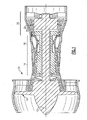
- Figure 1 illustrates selected portions of an example gas turbine engine 10, such as a gas turbine engine 10 used for propulsion.
- the gas turbine engine 10 is circumferentially disposed about an engine centerline 12.
- the engine 10 includes a fan 14, a compressor section 16, a combustion section 18 and a turbine section 20 that includes turbine blades 22 and turbine vanes 24.
- air compressed in the compressor section 16 is mixed with fuel and burned in the combustion section 18 to produce hot gases that are expanded in the turbine section 20.
- Figure 1 is a somewhat schematic presentation for illustrative purposes only and is not a limitation on the disclosed examples. Additionally, there are various types of gas turbine engines, many of which could benefit from the examples disclosed herein, which are not limited to the design shown.
- FIG 2 illustrates selected portions of the turbine section 20.
- the turbine blade 22 receives a hot gas flow 26 from the combustion section 18 ( Figure 1 ).
- the turbine section 20 includes a blade outer air seal system 28 having a seal member 30 that functions as an outer wall for the hot gas flow 26 through the turbine section 20.
- the seal member 30 is secured to a support 32, which is in turn secured to a case 34 that generally surrounds the turbine section 20.
- a plurality of the seal members 30 are located circumferentially about the turbine section 20.
- Figure 3 illustrates an example portion 44 of the seal member 30.
- the seal member 30 includes a substrate 46 having a thermal barrier system 48 disposed thereon.
- the thermal barrier system 48 includes an abradable ceramic member 50 and, optionally, a bond coat 52 between the ceramic member 50 and the substrate 46.
- the ceramic member 50 includes a thickness 66 along a direction generally perpendicular to the surface of the substrate 46.
- the thickness 66 is between about 20 mils (0.051 cm) and 150 mils (0.381 cm).
- the thickness 66 is between about 20 mils (0.051 cm) and 50 mils (0.127 cm).
- a particular thermal barrier system 48 is disclosed, it is to be understood that the disclosed examples are not limited to the illustrated configuration and may include additional layers.
- the seal member 30 is shown, it is to be understood that the disclosed examples may also be applied to other types of engine components such as the turbine blades 22 or turbine vanes 24, or to non-engine components.
- the ceramic member 50 includes closed pores 54 that are encased within a ceramic matrix 56. That is, the closed pores 54 are not fluidly interconnected with each other or with the surrounding environment of the ceramic member 50.
- the ceramic member 50 provides several benefits.
- the presence of the closed pores 54 enhances the thermal resistance of the ceramic member 50 for withstanding sintering and shrinking due to elevated temperatures within the turbine section 20. That is, the void volume enclosed within the closed pores 54 functions as insulation to resist heat transfer through the ceramic member 50 to thereby maintain the ceramic member 50 below its sintering temperature.
- the presence of the closed pores 54 within the ceramic matrix 56 reduces a sintering rate of the ceramic matrix 56. That is, the closed pores 54 have a larger average radius of curvature, larger average pore size, and an increased volume to internal surface area ratio of the ceramic member 50, which in turn reduces the sintering rate of the ceramic matrix 56.
- the closed pore structure of the ceramic member 50 also provides the benefit of maintaining and enhancing efficiency of the turbine engine 10.
- hot gas flow through the turbine section 20 generally flows around the tips of the turbine blades 22.
- the closed pore structure prevents at least a portion of the hot gas flow from flowing through the ceramic matrix 56 around the blade tips, as might occur with an open pore structure.
- the closed pore structure prevents debris from infiltrating into the ceramic member 50, which might otherwise melt and react with the ceramic matrix 56, bond coat 52, or substrate 46 to form contaminant phases that detriment the mechanical integrity of the outer air seal 30.
- the ceramic member 50 comprises a selected type of ceramic material and includes a selected volume of the closed pores 54.
- the ceramic matrix 56 includes at least one of yttria stabilized zirconia, zirconia, hafnia, gadolinia, molybdenum disulphide, alumina, or mullite.
- the hafnia, zirconia, or gadolinia of the disclosed examples is selected from a composition disclosed in U.S. Patent No. 6,284,323 or U.S. Patent No. 6,924,040 . Given this description, one of ordinary skill in the art will recognize other types of ceramic materials to meet their particular needs.
- the ceramic member 50 may be manufactured with a selected volume of the closed pores 54 to achieve a desired level of thermal resistance.
- the volume of the closed pores 54 is between 20 vol% and 80 vol% of the ceramic member 50.
- the volume of the closed pores 54 is between 33 vol% and 66 vol%.
- the volume of the closed pores 54 is about 66 vol%.
- a relatively larger volume of the closed pores 54 may be used to achieve a greater insulating effect and a corresponding greater abradability and reduced elastic modulus.
- the ceramic member 50 may be manufactured in any of a variety of different methods, including as a coating on the substrate 46 or bond layer 52 or as a separate piece that is then later attached to the substrate 46 or bond coat 52.
- Figure 4 illustrates one example method 70 for forming the ceramic member 50.
- a ceramic powder comprising one or more of the ceramic materials described above is compacted under pressure at step 72.
- ceramic processing that utilizes a powder compaction technique compacts the powder to near 100% theoretical density.
- the ceramic powder is compacted to 40% to 60% theoretical density to later form the closed pores 54.
- the ceramic powder is compacted to 50% theoretical density.
- theoretical density refers to the fully dense material, and may be found in common reference materials or determined through known calculations.
- various binders and lubricants may be intermixed with the ceramic powder particles before step 72.
- minimal amounts of binders and lubricants are used because of hindrance to compaction.
- relatively larger amounts of the binders and lubricants may be used to achieve a desired level of compacted theoretical density.
- the compacted ceramic powder is sintered at step 74 to form the ceramic member 50.
- the sintering includes heating the compacted ceramic powder particles at a predetermined sintering temperature to cause diffusion of the ceramic powder particles.
- the partial diffusing of the ceramic powder particles does not completely fill the intra-particle pores that resulted from partial compacting at step 72, leaving the closed pores 54 after the sintering step 74.
- compacting the ceramic powder particles at step 72 between the 40% and the 60% theoretical density results in closed pores 54 that comprise 30 vol% of the ceramic member 50.
- the ceramic composition and sintering temperature may result in partial melting of the ceramic material and the formation of a liquid phase that facilitates densification.
- the compacted ceramic powder particles are less than 100% sintered.
- sintering times and sintering temperatures may be determined experimentally, such that a selected sintering temperature and sintering time results in less than 100% sintering of the ceramic powder particles. Sintering the ceramic powder particles less than 100% provides the benefit of preventing the ceramic powder particles from diffusing into the intra-particle pores thereby providing a greater volume of the final formed closed pores 54.
- the compacted ceramic powder particles are sintered to form a fully sintered ceramic matrix 56 (i.e., the ceramic matrix 56 is at or near 100% theoretical density, not counting the volume of the closed pores 54).
- the ceramic matrix 56 is at or near 100% theoretical density, not counting the volume of the closed pores 54.
- this may be achieved by sintering sub-micron ceramic particles for a relatively long time at a relatively high temperature until the ceramic crystals become equiaxed and the driving force for sintering is diminished to the point where sintering shrinkage slows to a negligible rate.
- a bimodal pore size distribution of the intra-particle pores may be created in the compacted ceramic powder particles by using a fraction of hollow spheres, fugitive particles, agglomerated sub-micron or nano-particles, etc.
- the smaller ones of the intra-particle pores would then sinter at a much higher rate, to provide the ceramic matrix 56 having a higher density than the apparent density of the entire ceramic member 50.
- the ceramic matrix 56 may then be characterized by its own apparent density, pore size and sintering rate, while the ceramic member 50 as a whole may be characterized by its own apparent density, pore size and sintering rate.
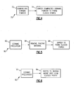
- Figure 5 illustrates another example method 80 for forming the closed pores 54.
- a ceramic precursor is formed into a desired shape at step 82.
- the ceramic precursor is a slurry having ceramic powder particles and a pore-forming agent, such as a fugitive material.
- the fugitive material is a material that can later be removed, such as by heating at a predetermined temperature to liquefy or vaporize the fugitive material.
- the fugitive material may include an organic material, such as corn starch or wax.
- the fugitive material includes a polymer, such as polyester or polymethylmethacrylate, or graphite. Given this description, one of ordinary skill in the art will recognize other types of polymers and solids that may be used as a fugitive material.
- the slurry of the above example includes ceramic precursor such as a preceramic polymer, salt or other compound that when heated undergoes a change to form the ceramic matrix 56.
- ceramic precursor such as a preceramic polymer, salt or other compound that when heated undergoes a change to form the ceramic matrix 56.
- These types of ceramic precursors may be used as a binder in the above example slurry, or may be used alone. In some examples, these types of ceramic precursors have a volumetric shrinkage and outgas during thermal treatment, which may be advantageous for controlling the structure of the closed pores 54.
- the fugitive material is removed from the ceramic powder particles.
- the solvent may first be removed by evaporation over a period of time, by heating the slurry at a predetermined temperature, or in combination with removal of the fugitive material.
- the fugitive material is removed by heating at predetermined temperature to liquefy or vaporize the fugitive material.
- the graphite may be oxidized in air to form gaseous carbon dioxide product.
- the ceramic powder particles are sintered at a predetermined sintering temperature to at least partially densify the ceramic powder particles. As described above, diffusion of the ceramic powder particles does not completely densify the intra-particle pores. Thus, the ceramic powder particles densify around the pores to form the closed pores 54.
- Figure 6 illustrates another example method 90 for forming the closed pores 54.
- a ceramic precursor is used to form the ceramic member 50.
- the ceramic precursor may include a slurry having ceramic powder particles and a pore-forming agent suspended in a solvent.
- the slurry may be formed into a desired shape, such as by tape casting.
- the pore-forming agent includes a sintering material that reduces in size (i.e., shrinks) upon sintering to leave a pore volume within the surrounding ceramic powder particles or densified ceramic matrix 56.
- the sintering material comprises agglomerates of nano-sized ceramic particles that shrink upon being heated to a predetermined sintering temperature.
- the ceramic precursor and sintering material are heated at a predetermined temperature after removal of the solvent to sinter the sintering material and thereby produce intra-particle pores between the ceramic powder particles.
- Shrinking of the sintering material may be conducted separately from, or in combination with, sintering of the ceramic powder particles to densify the ceramic matrix 56 around the intra-particle pores to form the closed pores 54.
Landscapes
- Chemical & Material Sciences (AREA)
- Engineering & Computer Science (AREA)
- Ceramic Engineering (AREA)
- Materials Engineering (AREA)
- Organic Chemistry (AREA)
- Manufacturing & Machinery (AREA)
- Structural Engineering (AREA)
- Mechanical Engineering (AREA)
- Inorganic Chemistry (AREA)
- General Engineering & Computer Science (AREA)
- Chemical Kinetics & Catalysis (AREA)
- Metallurgy (AREA)
- Turbine Rotor Nozzle Sealing (AREA)
- Porous Artificial Stone Or Porous Ceramic Products (AREA)
- Composite Materials (AREA)
Abstract
Description
- This invention relates to thermal barriers and, more particularly, to abradable ceramic thermal barrier systems and methods of manufacture.
- Components that are exposed to high temperatures, such as gas turbine engine components, typically include a protective coating system having one or more coating layers. For example, turbine blades, turbine vanes, and blade outer air seals typically include the coating system to protect from erosion, oxidation, corrosion or the like and thereby enhance durability or maintain efficient operation of the engine. In particular, conventional outer air seals include an abradable ceramic coating that contacts tips of the turbine blades during engine operation such that the blades abrade the coating upon operation of the engine. The abrasion between the coating and blade tips provides a minimum clearance between these components such that gas flow around the tips of the blades is reduced to thereby maintain engine efficiency.
- One drawback of the abradable ceramic coating is its vulnerability to erosion and spalling. For example, spalling may occur as a loss of portions of the coating that detach from the component. Loss of the coating increases clearance between the outer air seal and the blade tips and is detrimental to the turbine engine efficiency. One cause of spalling is the elevated temperature within the turbine section, which causes sintering of the ceramic coating. The sintering causes the coating to shrink, which produces stresses between the coating the component. If the stresses are great enough, the coating may delaminate and detach from the component.
- Accordingly, there is a need for a thermal barrier system having enhanced thermal resistance to resist sintering and shrinkage during engine operation and a method for manufacturing the thermal barrier system. This invention addresses those needs while avoiding the shortcomings and drawbacks of the prior art.
- An example composite article includes a substrate and a thermal barrier secured to the substrate. The thermal barrier includes a plurality of closed pores within a ceramic matrix. For example, the closed pores comprise 20 vol% to 80 vol% of the thermal barrier.
- An example method of manufacturing the thermal barrier includes forming the plurality of closed pores within the ceramic matrix. For example, the closed pores are formed using a pore-forming agent that is later removed or reduced in size to form the closed pores.
- In one example, the composite article is a turbine blade outer air seal for use in a gas turbine engine. For example, the substrate comprises a body and the thermal barrier is secured to the body for providing thermal resistance to a hot gas flow.
- The various features and advantages of this invention will become apparent to those skilled in the art from the following detailed description of the currently preferred embodiment. The drawings that accompany the detailed description can be briefly described as follows.
-
Figure 1 illustrates an example gas turbine engine. -
Figure 2 illustrates a turbine section of the gas turbine engine. -
Figure 3 illustrates a portion of a seal member within the turbine section. -
Figure 4 illustrates an example method of forming a ceramic member having closed pores. -
Figure 5 illustrates another example method of forming a ceramic member having closed pores. -
Figure 6 illustrates another example method of forming a ceramic member having closed pores. -
Figure 1 illustrates selected portions of an examplegas turbine engine 10, such as agas turbine engine 10 used for propulsion. In this example, thegas turbine engine 10 is circumferentially disposed about anengine centerline 12. Theengine 10 includes afan 14, acompressor section 16, acombustion section 18 and aturbine section 20 that includesturbine blades 22 andturbine vanes 24. As is known, air compressed in thecompressor section 16 is mixed with fuel and burned in thecombustion section 18 to produce hot gases that are expanded in theturbine section 20.Figure 1 is a somewhat schematic presentation for illustrative purposes only and is not a limitation on the disclosed examples. Additionally, there are various types of gas turbine engines, many of which could benefit from the examples disclosed herein, which are not limited to the design shown. -
Figure 2 illustrates selected portions of theturbine section 20. Theturbine blade 22 receives ahot gas flow 26 from the combustion section 18 (Figure 1 ). Theturbine section 20 includes a blade outerair seal system 28 having aseal member 30 that functions as an outer wall for thehot gas flow 26 through theturbine section 20. Theseal member 30 is secured to asupport 32, which is in turn secured to acase 34 that generally surrounds theturbine section 20. For example, a plurality of theseal members 30 are located circumferentially about theturbine section 20. -
Figure 3 illustrates anexample portion 44 of theseal member 30. In this example, theseal member 30 includes asubstrate 46 having athermal barrier system 48 disposed thereon. Thethermal barrier system 48 includes an abradableceramic member 50 and, optionally, abond coat 52 between theceramic member 50 and thesubstrate 46. Theceramic member 50 includes athickness 66 along a direction generally perpendicular to the surface of thesubstrate 46. For example, thethickness 66 is between about 20 mils (0.051 cm) and 150 mils (0.381 cm). In a further example, thethickness 66 is between about 20 mils (0.051 cm) and 50 mils (0.127 cm). Although a particularthermal barrier system 48 is disclosed, it is to be understood that the disclosed examples are not limited to the illustrated configuration and may include additional layers. Furthermore, although theseal member 30 is shown, it is to be understood that the disclosed examples may also be applied to other types of engine components such as theturbine blades 22 orturbine vanes 24, or to non-engine components. - In this disclosed example, the
ceramic member 50 includes closedpores 54 that are encased within aceramic matrix 56. That is, the closedpores 54 are not fluidly interconnected with each other or with the surrounding environment of theceramic member 50. - The
ceramic member 50 provides several benefits. For example, the presence of the closedpores 54 enhances the thermal resistance of theceramic member 50 for withstanding sintering and shrinking due to elevated temperatures within theturbine section 20. That is, the void volume enclosed within the closedpores 54 functions as insulation to resist heat transfer through theceramic member 50 to thereby maintain theceramic member 50 below its sintering temperature. Additionally, the presence of the closedpores 54 within theceramic matrix 56 reduces a sintering rate of theceramic matrix 56. That is, the closedpores 54 have a larger average radius of curvature, larger average pore size, and an increased volume to internal surface area ratio of theceramic member 50, which in turn reduces the sintering rate of theceramic matrix 56. This is because the methods of manufacture of a closed pore structure create a fully or nearly fully densified matrix. Thus, if the temperature in theturbine section 20 does exceed the sintering temperature, the closedpores 54 reduce the rate at which theceramic member 50 sinters. - The closed pore structure of the
ceramic member 50 also provides the benefit of maintaining and enhancing efficiency of theturbine engine 10. For example, hot gas flow through theturbine section 20 generally flows around the tips of theturbine blades 22. The closed pore structure prevents at least a portion of the hot gas flow from flowing through theceramic matrix 56 around the blade tips, as might occur with an open pore structure. Moreover, the closed pore structure prevents debris from infiltrating into theceramic member 50, which might otherwise melt and react with theceramic matrix 56,bond coat 52, orsubstrate 46 to form contaminant phases that detriment the mechanical integrity of theouter air seal 30. - The
ceramic member 50 comprises a selected type of ceramic material and includes a selected volume of the closedpores 54. For example, theceramic matrix 56 includes at least one of yttria stabilized zirconia, zirconia, hafnia, gadolinia, molybdenum disulphide, alumina, or mullite. In a further example, the hafnia, zirconia, or gadolinia of the disclosed examples is selected from a composition disclosed inU.S. Patent No. 6,284,323 orU.S. Patent No. 6,924,040 . Given this description, one of ordinary skill in the art will recognize other types of ceramic materials to meet their particular needs. - The
ceramic member 50 may be manufactured with a selected volume of theclosed pores 54 to achieve a desired level of thermal resistance. For example, the volume of theclosed pores 54 is between 20 vol% and 80 vol% of theceramic member 50. In a further example, the volume of theclosed pores 54 is between 33 vol% and 66 vol%. In a further example, the volume of theclosed pores 54 is about 66 vol%. As can be appreciated, a relatively larger volume of theclosed pores 54 may be used to achieve a greater insulating effect and a corresponding greater abradability and reduced elastic modulus. - The
ceramic member 50 may be manufactured in any of a variety of different methods, including as a coating on thesubstrate 46 orbond layer 52 or as a separate piece that is then later attached to thesubstrate 46 orbond coat 52.Figure 4 illustrates oneexample method 70 for forming theceramic member 50. In this example, a ceramic powder comprising one or more of the ceramic materials described above is compacted under pressure atstep 72. Typically, ceramic processing that utilizes a powder compaction technique compacts the powder to near 100% theoretical density. However, atsteps 72, the ceramic powder is compacted to 40% to 60% theoretical density to later form the closed pores 54. In a further example, the ceramic powder is compacted to 50% theoretical density. By compacting to the disclosed levels of theoretical density, intra-particle pores are formed between the ceramic powder particles that will later result in formation of theclosed pores 54 upon sintering densification of the ceramic powder. The term "theoretical density" as used in this description refers to the fully dense material, and may be found in common reference materials or determined through known calculations. - Optionally, various binders and lubricants may be intermixed with the ceramic powder particles before
step 72. Typically, minimal amounts of binders and lubricants are used because of hindrance to compaction. However, since partial compaction is desired atstep 72, relatively larger amounts of the binders and lubricants may be used to achieve a desired level of compacted theoretical density. - After compacting at
steps 72, the compacted ceramic powder is sintered atstep 74 to form theceramic member 50. For example, the sintering includes heating the compacted ceramic powder particles at a predetermined sintering temperature to cause diffusion of the ceramic powder particles. The partial diffusing of the ceramic powder particles does not completely fill the intra-particle pores that resulted from partial compacting atstep 72, leaving theclosed pores 54 after thesintering step 74. In one example, compacting the ceramic powder particles atstep 72 between the 40% and the 60% theoretical density results inclosed pores 54 that comprise 30 vol% of theceramic member 50. In a second example, the ceramic composition and sintering temperature may result in partial melting of the ceramic material and the formation of a liquid phase that facilitates densification. - Additionally, the compacted ceramic powder particles are less than 100% sintered. For example, sintering times and sintering temperatures may be determined experimentally, such that a selected sintering temperature and sintering time results in less than 100% sintering of the ceramic powder particles. Sintering the ceramic powder particles less than 100% provides the benefit of preventing the ceramic powder particles from diffusing into the intra-particle pores thereby providing a greater volume of the final formed closed pores 54.
- In another example, the compacted ceramic powder particles are sintered to form a fully sintered ceramic matrix 56 (i.e., the
ceramic matrix 56 is at or near 100% theoretical density, not counting the volume of the closed pores 54). For example, this may be achieved by sintering sub-micron ceramic particles for a relatively long time at a relatively high temperature until the ceramic crystals become equiaxed and the driving force for sintering is diminished to the point where sintering shrinkage slows to a negligible rate. Alternately, a bimodal pore size distribution of the intra-particle pores may be created in the compacted ceramic powder particles by using a fraction of hollow spheres, fugitive particles, agglomerated sub-micron or nano-particles, etc. The smaller ones of the intra-particle pores would then sinter at a much higher rate, to provide theceramic matrix 56 having a higher density than the apparent density of the entireceramic member 50. Theceramic matrix 56 may then be characterized by its own apparent density, pore size and sintering rate, while theceramic member 50 as a whole may be characterized by its own apparent density, pore size and sintering rate. -
Figure 5 illustrates anotherexample method 80 for forming the closed pores 54. In this example, a ceramic precursor is formed into a desired shape atstep 82. For example, the ceramic precursor is a slurry having ceramic powder particles and a pore-forming agent, such as a fugitive material. The fugitive material is a material that can later be removed, such as by heating at a predetermined temperature to liquefy or vaporize the fugitive material. For example, the fugitive material may include an organic material, such as corn starch or wax. In another example, the fugitive material includes a polymer, such as polyester or polymethylmethacrylate, or graphite. Given this description, one of ordinary skill in the art will recognize other types of polymers and solids that may be used as a fugitive material. - In another example, the slurry of the above example includes ceramic precursor such as a preceramic polymer, salt or other compound that when heated undergoes a change to form the
ceramic matrix 56. These types of ceramic precursors may be used as a binder in the above example slurry, or may be used alone. In some examples, these types of ceramic precursors have a volumetric shrinkage and outgas during thermal treatment, which may be advantageous for controlling the structure of the closed pores 54. - At
step 84, the fugitive material is removed from the ceramic powder particles. The solvent may first be removed by evaporation over a period of time, by heating the slurry at a predetermined temperature, or in combination with removal of the fugitive material. The fugitive material is removed by heating at predetermined temperature to liquefy or vaporize the fugitive material. For example, the graphite may be oxidized in air to form gaseous carbon dioxide product. - The removal of the fugitive material leaves intra-particle pores between the ceramic powder particles. At
step 86, the ceramic powder particles are sintered at a predetermined sintering temperature to at least partially densify the ceramic powder particles. As described above, diffusion of the ceramic powder particles does not completely densify the intra-particle pores. Thus, the ceramic powder particles densify around the pores to form the closed pores 54. -
Figure 6 illustrates anotherexample method 90 for forming the closed pores 54. In this example, similar to the example shown inFigure 5 , a ceramic precursor is used to form theceramic member 50. The ceramic precursor may include a slurry having ceramic powder particles and a pore-forming agent suspended in a solvent. The slurry may be formed into a desired shape, such as by tape casting. - The pore-forming agent includes a sintering material that reduces in size (i.e., shrinks) upon sintering to leave a pore volume within the surrounding ceramic powder particles or densified
ceramic matrix 56. For example, the sintering material comprises agglomerates of nano-sized ceramic particles that shrink upon being heated to a predetermined sintering temperature. - At
step 94, the ceramic precursor and sintering material are heated at a predetermined temperature after removal of the solvent to sinter the sintering material and thereby produce intra-particle pores between the ceramic powder particles. Shrinking of the sintering material may be conducted separately from, or in combination with, sintering of the ceramic powder particles to densify theceramic matrix 56 around the intra-particle pores to form the closed pores 54. - Although a combination of features is shown in the illustrated examples, not all of them need to be combined to realize the benefits of various embodiments of this disclosure. In other words, a system designed according to an embodiment of this disclosure will not necessarily include all of the features shown in any one of the Figures or all of the portions schematically shown in the Figures. Moreover, selected features of one example embodiment may be combined with selected features of other example embodiments.
- The preceding description is exemplary rather than limiting in nature. Variations and modifications to the disclosed examples may become apparent to those skilled in the art that do not necessarily depart from the essence of this disclosure. The scope of legal protection given to this disclosure can only be determined by studying the following claims.
Claims (20)
- A composite article (30) comprising:a substrate (46); anda thermal barrier (48) secured to the substrate (46), the thermal barrier (48) comprising a plurality of closed pores (54) within a ceramic matrix (56).
- The composite article as recited in Claim 1, wherein the plurality of closed pores (54) are each entirely surrounded by the ceramic matrix (56).
- The composite article as recited in Claim 1 or 2, wherein the plurality of closed pores (54) comprise about 20 vol% to 80 vol% of the thermal barrier (48).
- The composite article as recited in Claim 3, wherein the plurality of closed pores (54) comprise about 33 vol% to 66 vol% of the thermal barrier (48).
- The composite article as recited in Claim 3, wherein the plurality of closed pores (54) comprise about 66 vol% of the thermal barrier (48).
- The composite article as recited in any preceding Claim, further comprising a bond coat (52) between the substrate (46) and the thermal barrier (48).
- The composite article as recited in any preceding Claim, wherein the ceramic matrix (56) comprises at least one of yttria stabilized zirconia, zirconia, hafnia, gadolinia, molybdenum disilicide, alumina, or mullite.
- The composite article as recited in any preceding Claim, wherein the thermal barrier (48) comprises a thickness of about 20 mils (0.051 cm) to 150 mils (0.381 cm).
- The composite article as recited in Claim 8, wherein the thickness is about 20 mils (0.051 cm) to 50 mils (0.127 cm).
- A method of manufacturing a thermal barrier (48), comprising:forming the thermal barrier (48) with a plurality of closed pores (54) within a ceramic matrix (56).
- The method as recited in Claim 10, further comprising compacting (72) a ceramic powder to 40% to 60% theoretical density and sintering (74) the ceramic powder.
- The method as recited in Claim 11, including compacting (72) the ceramic powder to 50% theoretical density.
- The method as recited in Claim 10, further comprising forming the thermal barrier from a ceramic having a pore-forming agent.
- The method as recited in Claim 13, including heating (84) the ceramic to remove the pore-forming agent and thereby form the closed pores (54).
- The method as recited in Claim 14, including selecting the pore-forming agent to include at least one of an organic material, a polymer or graphite.
- The method as recited in Claim 13, including sintering (94) the pore-forming agent to reduce the size of the pore-forming agent and thereby form the closed pores (54).
- The method as recited in Claim 16, including selecting the pore-forming agent to include nano-sized ceramic particles.
- The method as recited in Claim 10, further comprising forming the thermal barrier (48) from at least one of: a preceramic polymer or a salt that when heated forms the ceramic matrix, or a slurry comprising ceramic particles or preceramic polymer and a solvent.
- A turbine blade outer air seal (30) comprising:a body (46) extending between two circumferential sides, a leading edge and a trailing edge, and a radially inner side and a radially outer side; anda thermal barrier (48) secured to the body (46), the thermal barrier (48) comprising a plurality of closed pores (54) within a ceramic matrix (56).
- The turbine blade outer air seal as recited in Claim 19, wherein the plurality of closed pores (54) comprise about 33 vol% to 66 vol% of the thermal barrier (48), the ceramic matrix (56) comprises at least one of yttria stabilized zirconia, zirconia, hafnia, gadolinia, molybdenum disilicide, alumina, or mullite, and wherein the thermal barrier (48) comprises a thickness between about 20 mils (0.051 cm) and 50 mils (0.127 cm).
Applications Claiming Priority (1)
| Application Number | Priority Date | Filing Date | Title |
|---|---|---|---|
| US11/755,281 US9447503B2 (en) | 2007-05-30 | 2007-05-30 | Closed pore ceramic composite article |
Publications (3)
| Publication Number | Publication Date |
|---|---|
| EP1997929A2 true EP1997929A2 (en) | 2008-12-03 |
| EP1997929A3 EP1997929A3 (en) | 2010-09-01 |
| EP1997929B1 EP1997929B1 (en) | 2021-10-13 |
Family
ID=39512787
Family Applications (1)
| Application Number | Title | Priority Date | Filing Date |
|---|---|---|---|
| EP08250952.2A Active EP1997929B1 (en) | 2007-05-30 | 2008-03-19 | Method for making a gas turbine outer air seal with closed pores |
Country Status (3)
| Country | Link |
|---|---|
| US (3) | US9447503B2 (en) |
| EP (1) | EP1997929B1 (en) |
| JP (1) | JP2008297193A (en) |
Cited By (1)
| Publication number | Priority date | Publication date | Assignee | Title |
|---|---|---|---|---|
| WO2015130362A3 (en) * | 2013-12-12 | 2015-11-05 | General Electric Company | Method of depositing abradable coatings under polymer gels |
Families Citing this family (35)
| Publication number | Priority date | Publication date | Assignee | Title |
|---|---|---|---|---|
| CA2619509C (en) | 2005-08-12 | 2015-01-06 | Modumetal, Llc. | Compositionally modulated composite materials and methods for making the same |
| JP2010151267A (en) * | 2008-12-26 | 2010-07-08 | Hitachi Ltd | Seal structure and gas turbine using the same |
| BRPI1010877B1 (en) | 2009-06-08 | 2020-09-15 | Modumetal, Inc | CORROSION RESISTANT MULTILAYER COATING AND ELECTRODEPOSITION METHOD |
| FR2996874B1 (en) * | 2012-10-11 | 2014-12-19 | Turbomeca | ROTOR-STATOR ASSEMBLY FOR GAS TURBINE ENGINE |
| US10301949B2 (en) * | 2013-01-29 | 2019-05-28 | United Technologies Corporation | Blade rub material |
| EA201500948A1 (en) | 2013-03-15 | 2016-03-31 | Модьюметл, Инк. | METHOD OF MANUFACTURING A PRODUCT AND A PRODUCT MANUFACTURED BY THE ABOVE INDICATED BY THE METHOD |
| WO2014146117A2 (en) | 2013-03-15 | 2014-09-18 | Modumetal, Inc. | A method and apparatus for continuously applying nanolaminate metal coatings |
| BR112015022020A8 (en) | 2013-03-15 | 2019-12-10 | Modumetal Inc | object or coating and its manufacturing process |
| CA2905548C (en) | 2013-03-15 | 2022-04-26 | Modumetal, Inc. | Nanolaminate coatings |
| EP2789804A1 (en) | 2013-04-11 | 2014-10-15 | Alstom Technology Ltd | Gas turbine thermal shroud with improved durability |
| US10647618B2 (en) | 2014-09-19 | 2020-05-12 | Hrl Laboratories, Llc | Thermal and environmental barrier coating for ceramic substrates |
| WO2016153543A2 (en) * | 2015-03-24 | 2016-09-29 | Hrl Laboratories, Llc | Thermal and environmental barrier coating for ceramic substrates |
| BR112017005534A2 (en) | 2014-09-18 | 2017-12-05 | Modumetal Inc | Methods of preparing articles by electrodeposition processes and additive manufacturing |
| EP3194642A4 (en) | 2014-09-18 | 2018-07-04 | Modumetal, Inc. | A method and apparatus for continuously applying nanolaminate metal coatings |
| FR3040461B1 (en) * | 2015-09-02 | 2018-02-23 | Safran Aircraft Engines | LABYRINTH SEALING ELEMENT FOR TURBINE |
| US10883385B2 (en) | 2016-08-29 | 2021-01-05 | Raytheon Technologies Corporation | Thermal barrier washer |
| US10697325B2 (en) | 2016-08-29 | 2020-06-30 | Raytheon Technologies Corporation | Thermal barrier seal |
| US11365488B2 (en) | 2016-09-08 | 2022-06-21 | Modumetal, Inc. | Processes for providing laminated coatings on workpieces, and articles made therefrom |
| TW201821649A (en) | 2016-09-09 | 2018-06-16 | 美商馬杜合金股份有限公司 | Application of laminate and nano laminate materials in tools and molding methods |
| WO2018053158A1 (en) | 2016-09-14 | 2018-03-22 | Modumetal, Inc. | System for reliable, high throughput, complex electric field generation, and method for producing coatings therefrom |
| EP3535118A1 (en) | 2016-11-02 | 2019-09-11 | Modumetal, Inc. | Topology optimized high interface packing structures |
| JP6622176B2 (en) * | 2016-11-30 | 2019-12-18 | 三菱重工業株式会社 | High temperature components for gas turbines and gas turbines |
| CA3060619A1 (en) | 2017-04-21 | 2018-10-25 | Modumetal, Inc. | Tubular articles with electrodeposited coatings, and systems and methods for producing the same |
| US11230503B2 (en) | 2017-06-27 | 2022-01-25 | General Electric Company | Resin for production of porous ceramic stereolithography and methods of its use |
| KR102093293B1 (en) * | 2017-12-07 | 2020-03-26 | 한국생산기술연구원 | Nanoparticle structure containing vacuum-pore |
| EP3784823A1 (en) | 2018-04-27 | 2021-03-03 | Modumetal, Inc. | Apparatuses, systems, and methods for producing a plurality of articles with nanolaminated coatings using rotation |
| EP3611146B1 (en) * | 2018-08-16 | 2021-03-24 | Raytheon Technologies Corporation | Machinable coatings fabricated by slurry methods for use on ceramic matrix composites |
| US11148980B2 (en) | 2018-08-16 | 2021-10-19 | Raytheon Technologies Corporation | Protective coating for ceramic matrix composites |
| CN111393181B (en) * | 2020-03-20 | 2022-07-19 | 安徽金岩高岭土科技有限公司 | Preparation method of full-closed-pore porous mullite ceramic based on direct solidification injection molding |
| EP4108885A1 (en) * | 2021-06-25 | 2022-12-28 | ITP Next Generation Turbines, S.L. | Sealing structure and sealing system for gas turbine engine |
| WO2023086688A2 (en) * | 2021-08-09 | 2023-05-19 | Blueshift Materials, Inc. | Thermal protection laminates |
| US12410729B2 (en) | 2022-10-07 | 2025-09-09 | Rtx Corporation | Pre-ceramic thermal barrier for gas turbine engine components |
| CN115637402B (en) * | 2022-11-07 | 2023-09-01 | 哈尔滨工业大学 | Method for preparing high-temperature-resistant abradable seal coating with multistage holes or gradient holes based on electrostatic field auxiliary item conversion |
| US12146438B2 (en) * | 2023-02-13 | 2024-11-19 | Rtx Corporation | Gas turbine engine component with integrated sensor bracket |
| US12188365B1 (en) * | 2023-12-04 | 2025-01-07 | Rolls-Royce Corporation | Method and apparatus for ceramic matrix composite turbine shroud assembly |
Citations (7)
| Publication number | Priority date | Publication date | Assignee | Title |
|---|---|---|---|---|
| WO1999048837A1 (en) | 1998-03-27 | 1999-09-30 | Siemens Westinghouse Power Corporation | Use of high temperature insulation for ceramic matrix composites in gas turbines |
| WO2001073147A2 (en) | 2000-03-28 | 2001-10-04 | Siemens Westinghouse Power Corporation | Method for making a high temperature erosion resistant coating and material containing compacted hollow geometric shapes |
| JP2002128563A (en) | 2000-10-23 | 2002-05-09 | Nitsukatoo:Kk | Ceramic member for thermal treatment which has good thermal shock resistance |
| JP2002308678A (en) | 2001-02-08 | 2002-10-23 | Sumitomo Electric Ind Ltd | Porous ceramic and method for producing the same |
| JP2003040688A (en) | 2001-07-25 | 2003-02-13 | Nitsukatoo:Kk | Lightweight ceramic sintered compact |
| US20060019087A1 (en) | 1998-03-27 | 2006-01-26 | Siemens Power Generation, Inc. | Utilization of discontinuous fibers for improving properties of high temperature insulation for ceramic matrix composites |
| US7041366B2 (en) | 2001-09-04 | 2006-05-09 | Sumitomo Electric Industries, Ltd. | Porous silicon nitride ceramics and method for producing the same |
Family Cites Families (26)
| Publication number | Priority date | Publication date | Assignee | Title |
|---|---|---|---|---|
| US4247249A (en) * | 1978-09-22 | 1981-01-27 | General Electric Company | Turbine engine shroud |
| US4273824A (en) | 1979-05-11 | 1981-06-16 | United Technologies Corporation | Ceramic faced structures and methods for manufacture thereof |
| US4421671A (en) * | 1982-06-18 | 1983-12-20 | General Electric Company | Rare-earth-doped yttria-gadolinia ceramic scintillators |
| US4704332A (en) | 1982-11-01 | 1987-11-03 | United Technologies Corporation | Lightweight fiber reinforced high temperature stable glass-ceramic abradable seal |
| US4756895A (en) * | 1986-08-22 | 1988-07-12 | Stemcor Corporation | Hexagonal silicon carbide platelets and preforms and methods for making and using same |
| US4944861A (en) * | 1989-04-03 | 1990-07-31 | Barber-Colman Company | Oxygen sensing probe having improved sensor tip and tip-supporting tube |
| US5064727A (en) | 1990-01-19 | 1991-11-12 | Avco Corporation | Abradable hybrid ceramic wall structures |
| JPH06157157A (en) * | 1992-11-18 | 1994-06-03 | Inax Corp | Production of ceramics with closed pore |
| GB9513252D0 (en) * | 1995-06-29 | 1995-09-06 | Rolls Royce Plc | An abradable composition |
| US6102656A (en) | 1995-09-26 | 2000-08-15 | United Technologies Corporation | Segmented abradable ceramic coating |
| JPH09249457A (en) * | 1996-01-09 | 1997-09-22 | Sumitomo Electric Ind Ltd | Silicon nitride porous body having high strength and its production |
| US6835465B2 (en) | 1996-12-10 | 2004-12-28 | Siemens Westinghouse Power Corporation | Thermal barrier layer and process for producing the same |
| US6177200B1 (en) | 1996-12-12 | 2001-01-23 | United Technologies Corporation | Thermal barrier coating systems and materials |
| US6924040B2 (en) | 1996-12-12 | 2005-08-02 | United Technologies Corporation | Thermal barrier coating systems and materials |
| US6733907B2 (en) * | 1998-03-27 | 2004-05-11 | Siemens Westinghouse Power Corporation | Hybrid ceramic material composed of insulating and structural ceramic layers |
| US6443700B1 (en) | 2000-11-08 | 2002-09-03 | General Electric Co. | Transpiration-cooled structure and method for its preparation |
| US6428280B1 (en) | 2000-11-08 | 2002-08-06 | General Electric Company | Structure with ceramic foam thermal barrier coating, and its preparation |
| US6648596B1 (en) | 2000-11-08 | 2003-11-18 | General Electric Company | Turbine blade or turbine vane made of a ceramic foam joined to a metallic nonfoam, and preparation thereof |
| DE10222789B4 (en) * | 2002-05-23 | 2006-12-07 | Robert Bosch Gmbh | gas sensor |
| US6916529B2 (en) * | 2003-01-09 | 2005-07-12 | General Electric Company | High temperature, oxidation-resistant abradable coatings containing microballoons and method for applying same |
| AT6727U1 (en) | 2003-01-30 | 2004-03-25 | Plansee Ag | METHOD FOR PRODUCING POROUS SINTERED BODIES |
| US7207770B2 (en) * | 2003-05-27 | 2007-04-24 | General Electric Company | Variable stator vane bushings and washers |
| EP1541808A1 (en) * | 2003-12-11 | 2005-06-15 | Siemens Aktiengesellschaft | Turbine component with a heat- and erosion resistant coating |
| US7364802B2 (en) * | 2003-12-30 | 2008-04-29 | General Electric Company | Ceramic compositions useful in thermal barrier coatings having reduced thermal conductivity |
| US7282259B2 (en) | 2004-05-28 | 2007-10-16 | General Electric Company | Ceramic structures and methods of making them |
| US7354651B2 (en) * | 2005-06-13 | 2008-04-08 | General Electric Company | Bond coat for corrosion resistant EBC for silicon-containing substrate and processes for preparing same |
-
2007
- 2007-05-30 US US11/755,281 patent/US9447503B2/en active Active
-
2008
- 2008-03-19 EP EP08250952.2A patent/EP1997929B1/en active Active
- 2008-03-28 JP JP2008085109A patent/JP2008297193A/en active Pending
-
2016
- 2016-09-09 US US15/260,374 patent/US10669213B2/en active Active
-
2020
- 2020-06-01 US US16/889,068 patent/US20210107839A1/en not_active Abandoned
Patent Citations (7)
| Publication number | Priority date | Publication date | Assignee | Title |
|---|---|---|---|---|
| WO1999048837A1 (en) | 1998-03-27 | 1999-09-30 | Siemens Westinghouse Power Corporation | Use of high temperature insulation for ceramic matrix composites in gas turbines |
| US20060019087A1 (en) | 1998-03-27 | 2006-01-26 | Siemens Power Generation, Inc. | Utilization of discontinuous fibers for improving properties of high temperature insulation for ceramic matrix composites |
| WO2001073147A2 (en) | 2000-03-28 | 2001-10-04 | Siemens Westinghouse Power Corporation | Method for making a high temperature erosion resistant coating and material containing compacted hollow geometric shapes |
| JP2002128563A (en) | 2000-10-23 | 2002-05-09 | Nitsukatoo:Kk | Ceramic member for thermal treatment which has good thermal shock resistance |
| JP2002308678A (en) | 2001-02-08 | 2002-10-23 | Sumitomo Electric Ind Ltd | Porous ceramic and method for producing the same |
| JP2003040688A (en) | 2001-07-25 | 2003-02-13 | Nitsukatoo:Kk | Lightweight ceramic sintered compact |
| US7041366B2 (en) | 2001-09-04 | 2006-05-09 | Sumitomo Electric Industries, Ltd. | Porous silicon nitride ceramics and method for producing the same |
Cited By (2)
| Publication number | Priority date | Publication date | Assignee | Title |
|---|---|---|---|---|
| WO2015130362A3 (en) * | 2013-12-12 | 2015-11-05 | General Electric Company | Method of depositing abradable coatings under polymer gels |
| US10508059B2 (en) | 2013-12-12 | 2019-12-17 | General Electric Company | Method of depositing abradable coatings under polymer gels |
Also Published As
| Publication number | Publication date |
|---|---|
| EP1997929A3 (en) | 2010-09-01 |
| EP1997929B1 (en) | 2021-10-13 |
| US9447503B2 (en) | 2016-09-20 |
| US20170015597A1 (en) | 2017-01-19 |
| US20210107839A1 (en) | 2021-04-15 |
| US20090130424A1 (en) | 2009-05-21 |
| JP2008297193A (en) | 2008-12-11 |
| US10669213B2 (en) | 2020-06-02 |
Similar Documents
| Publication | Publication Date | Title |
|---|---|---|
| US20210107839A1 (en) | Method for closed pore ceramic | |
| EP2009141A2 (en) | Thermal barrier system and bonding method | |
| US11313243B2 (en) | Non-continuous abradable coatings | |
| RU2330162C2 (en) | High temperature foliated system for heat removal and method for its production (versions) | |
| EP1244605B1 (en) | High temperature erosion resistant coating and material containing compacted hollow geometric shapes | |
| US7905016B2 (en) | System for forming a gas cooled airfoil for use in a turbine engine | |
| EP1272441B1 (en) | Method for making a high temperature erosion resistant coating and material containing compacted hollow geometric shapes | |
| US7887929B2 (en) | Oriented fiber ceramic matrix composite abradable thermal barrier coating | |
| EP3037394A1 (en) | Environmental barrier coating with abradable coating for ceramic matrix composites | |
| US10989066B2 (en) | Abradable coating made of a material having a low surface roughness | |
| EP2508648B1 (en) | Component for a turbomachine and method for manufacturing such a component | |
| US8313288B2 (en) | Mechanical attachment of ceramic or metallic foam materials | |
| US6884384B2 (en) | Method for making a high temperature erosion resistant material containing compacted hollow geometric shapes | |
| JP6979761B2 (en) | Ceramic Matrix Composite Components and Ceramic Matrix Composites | |
| US20190093499A1 (en) | Non-continuous abradable coatings | |
| JP2017105698A5 (en) | ||
| EP2774754B1 (en) | Ceramic matrix composite component forming method | |
| US20160158964A1 (en) | Ceramic-encapsulated thermopolymer pattern or support with metallic plating | |
| CN117301260A (en) | Composite component and method of preventing flow from the permeable component during reinfiltration |
Legal Events
| Date | Code | Title | Description |
|---|---|---|---|
| PUAI | Public reference made under article 153(3) epc to a published international application that has entered the european phase |
Free format text: ORIGINAL CODE: 0009012 |
|
| AK | Designated contracting states |
Kind code of ref document: A2 Designated state(s): AT BE BG CH CY CZ DE DK EE ES FI FR GB GR HR HU IE IS IT LI LT LU LV MC MT NL NO PL PT RO SE SI SK TR |
|
| AX | Request for extension of the european patent |
Extension state: AL BA MK RS |
|
| PUAL | Search report despatched |
Free format text: ORIGINAL CODE: 0009013 |
|
| RIC1 | Information provided on ipc code assigned before grant |
Ipc: C04B 41/45 20060101ALI20100630BHEP Ipc: C23C 28/04 20060101ALI20100630BHEP Ipc: C23C 28/00 20060101ALI20100630BHEP Ipc: C23C 24/00 20060101ALI20100630BHEP Ipc: C23C 4/18 20060101ALI20100630BHEP Ipc: C23C 4/10 20060101AFI20080624BHEP |
|
| AK | Designated contracting states |
Kind code of ref document: A3 Designated state(s): AT BE BG CH CY CZ DE DK EE ES FI FR GB GR HR HU IE IS IT LI LT LU LV MC MT NL NO PL PT RO SE SI SK TR |
|
| AX | Request for extension of the european patent |
Extension state: AL BA MK RS |
|
| 17P | Request for examination filed |
Effective date: 20110301 |
|
| AKX | Designation fees paid |
Designated state(s): DE GB |
|
| TPAA | Information related to observations by third parties modified |
Free format text: ORIGINAL CODE: EPIDOSCTIPA |
|
| TPAC | Observations filed by third parties |
Free format text: ORIGINAL CODE: EPIDOSNTIPA |
|
| 17Q | First examination report despatched |
Effective date: 20160708 |
|
| RAP1 | Party data changed (applicant data changed or rights of an application transferred) |
Owner name: UNITED TECHNOLOGIES CORPORATION |
|
| STAA | Information on the status of an ep patent application or granted ep patent |
Free format text: STATUS: EXAMINATION IS IN PROGRESS |
|
| RAP1 | Party data changed (applicant data changed or rights of an application transferred) |
Owner name: RAYTHEON TECHNOLOGIES CORPORATION |
|
| REG | Reference to a national code |
Ref country code: DE Ref legal event code: R079 Ref document number: 602008064255 Country of ref document: DE Free format text: PREVIOUS MAIN CLASS: C23C0004100000 Ipc: C23C0028040000 |
|
| GRAP | Despatch of communication of intention to grant a patent |
Free format text: ORIGINAL CODE: EPIDOSNIGR1 |
|
| STAA | Information on the status of an ep patent application or granted ep patent |
Free format text: STATUS: GRANT OF PATENT IS INTENDED |
|
| RIC1 | Information provided on ipc code assigned before grant |
Ipc: C04B 111/00 20060101ALI20210416BHEP Ipc: C04B 38/00 20060101ALI20210416BHEP Ipc: C04B 35/58 20060101ALI20210416BHEP Ipc: C04B 35/48 20060101ALI20210416BHEP Ipc: C04B 35/10 20060101ALI20210416BHEP Ipc: C04B 41/45 20060101ALI20210416BHEP Ipc: C23C 28/04 20060101AFI20210416BHEP Ipc: C04B 35/185 20060101ALI20210416BHEP |
|
| INTG | Intention to grant announced |
Effective date: 20210520 |
|
| GRAS | Grant fee paid |
Free format text: ORIGINAL CODE: EPIDOSNIGR3 |
|
| GRAA | (expected) grant |
Free format text: ORIGINAL CODE: 0009210 |
|
| STAA | Information on the status of an ep patent application or granted ep patent |
Free format text: STATUS: THE PATENT HAS BEEN GRANTED |
|
| AK | Designated contracting states |
Kind code of ref document: B1 Designated state(s): DE GB |
|
| REG | Reference to a national code |
Ref country code: GB Ref legal event code: FG4D |
|
| REG | Reference to a national code |
Ref country code: DE Ref legal event code: R096 Ref document number: 602008064255 Country of ref document: DE |
|
| REG | Reference to a national code |
Ref country code: DE Ref legal event code: R097 Ref document number: 602008064255 Country of ref document: DE |
|
| PLBE | No opposition filed within time limit |
Free format text: ORIGINAL CODE: 0009261 |
|
| STAA | Information on the status of an ep patent application or granted ep patent |
Free format text: STATUS: NO OPPOSITION FILED WITHIN TIME LIMIT |
|
| 26N | No opposition filed |
Effective date: 20220714 |
|
| P01 | Opt-out of the competence of the unified patent court (upc) registered |
Effective date: 20230519 |
|
| REG | Reference to a national code |
Ref country code: DE Ref legal event code: R081 Ref document number: 602008064255 Country of ref document: DE Owner name: RTX CORPORATION (N.D.GES.D. STAATES DELAWARE),, US Free format text: FORMER OWNER: RAYTHEON TECHNOLOGIES CORPORATION, FARMINGTON, CT, US |
|
| PGFP | Annual fee paid to national office [announced via postgrant information from national office to epo] |
Ref country code: GB Payment date: 20260220 Year of fee payment: 19 |
|
| PGFP | Annual fee paid to national office [announced via postgrant information from national office to epo] |
Ref country code: DE Payment date: 20260219 Year of fee payment: 19 |