EP2508648B1 - Component for a turbomachine and method for manufacturing such a component - Google Patents
Component for a turbomachine and method for manufacturing such a component Download PDFInfo
- Publication number
- EP2508648B1 EP2508648B1 EP20120163023 EP12163023A EP2508648B1 EP 2508648 B1 EP2508648 B1 EP 2508648B1 EP 20120163023 EP20120163023 EP 20120163023 EP 12163023 A EP12163023 A EP 12163023A EP 2508648 B1 EP2508648 B1 EP 2508648B1
- Authority
- EP
- European Patent Office
- Prior art keywords
- base material
- component
- component according
- shell
- core
- Prior art date
- Legal status (The legal status is an assumption and is not a legal conclusion. Google has not performed a legal analysis and makes no representation as to the accuracy of the status listed.)
- Not-in-force
Links
Images


Classifications
-
- C—CHEMISTRY; METALLURGY
- C23—COATING METALLIC MATERIAL; COATING MATERIAL WITH METALLIC MATERIAL; CHEMICAL SURFACE TREATMENT; DIFFUSION TREATMENT OF METALLIC MATERIAL; COATING BY VACUUM EVAPORATION, BY SPUTTERING, BY ION IMPLANTATION OR BY CHEMICAL VAPOUR DEPOSITION, IN GENERAL; INHIBITING CORROSION OF METALLIC MATERIAL OR INCRUSTATION IN GENERAL
- C23C—COATING METALLIC MATERIAL; COATING MATERIAL WITH METALLIC MATERIAL; SURFACE TREATMENT OF METALLIC MATERIAL BY DIFFUSION INTO THE SURFACE, BY CHEMICAL CONVERSION OR SUBSTITUTION; COATING BY VACUUM EVAPORATION, BY SPUTTERING, BY ION IMPLANTATION OR BY CHEMICAL VAPOUR DEPOSITION, IN GENERAL
- C23C30/00—Coating with metallic material characterised only by the composition of the metallic material, i.e. not characterised by the coating process
-
- B—PERFORMING OPERATIONS; TRANSPORTING
- B22—CASTING; POWDER METALLURGY
- B22F—WORKING METALLIC POWDER; MANUFACTURE OF ARTICLES FROM METALLIC POWDER; MAKING METALLIC POWDER; APPARATUS OR DEVICES SPECIALLY ADAPTED FOR METALLIC POWDER
- B22F1/00—Metallic powder; Treatment of metallic powder, e.g. to facilitate working or to improve properties
- B22F1/16—Metallic particles coated with a non-metal
-
- B—PERFORMING OPERATIONS; TRANSPORTING
- B22—CASTING; POWDER METALLURGY
- B22F—WORKING METALLIC POWDER; MANUFACTURE OF ARTICLES FROM METALLIC POWDER; MAKING METALLIC POWDER; APPARATUS OR DEVICES SPECIALLY ADAPTED FOR METALLIC POWDER
- B22F1/00—Metallic powder; Treatment of metallic powder, e.g. to facilitate working or to improve properties
- B22F1/18—Non-metallic particles coated with metal
-
- B—PERFORMING OPERATIONS; TRANSPORTING
- B22—CASTING; POWDER METALLURGY
- B22F—WORKING METALLIC POWDER; MANUFACTURE OF ARTICLES FROM METALLIC POWDER; MAKING METALLIC POWDER; APPARATUS OR DEVICES SPECIALLY ADAPTED FOR METALLIC POWDER
- B22F10/00—Additive manufacturing of workpieces or articles from metallic powder
- B22F10/20—Direct sintering or melting
- B22F10/28—Powder bed fusion, e.g. selective laser melting [SLM] or electron beam melting [EBM]
-
- B—PERFORMING OPERATIONS; TRANSPORTING
- B22—CASTING; POWDER METALLURGY
- B22F—WORKING METALLIC POWDER; MANUFACTURE OF ARTICLES FROM METALLIC POWDER; MAKING METALLIC POWDER; APPARATUS OR DEVICES SPECIALLY ADAPTED FOR METALLIC POWDER
- B22F5/00—Manufacture of workpieces or articles from metallic powder characterised by the special shape of the product
- B22F5/009—Manufacture of workpieces or articles from metallic powder characterised by the special shape of the product of turbine components other than turbine blades
-
- B—PERFORMING OPERATIONS; TRANSPORTING
- B33—ADDITIVE MANUFACTURING TECHNOLOGY
- B33Y—ADDITIVE MANUFACTURING, i.e. MANUFACTURING OF THREE-DIMENSIONAL [3-D] OBJECTS BY ADDITIVE DEPOSITION, ADDITIVE AGGLOMERATION OR ADDITIVE LAYERING, e.g. BY 3-D PRINTING, STEREOLITHOGRAPHY OR SELECTIVE LASER SINTERING
- B33Y80/00—Products made by additive manufacturing
-
- C—CHEMISTRY; METALLURGY
- C22—METALLURGY; FERROUS OR NON-FERROUS ALLOYS; TREATMENT OF ALLOYS OR NON-FERROUS METALS
- C22C—ALLOYS
- C22C47/00—Making alloys containing metallic or non-metallic fibres or filaments
- C22C47/02—Pretreatment of the fibres or filaments
- C22C47/06—Pretreatment of the fibres or filaments by forming the fibres or filaments into a preformed structure, e.g. using a temporary binder to form a mat-like element
-
- C—CHEMISTRY; METALLURGY
- C22—METALLURGY; FERROUS OR NON-FERROUS ALLOYS; TREATMENT OF ALLOYS OR NON-FERROUS METALS
- C22C—ALLOYS
- C22C47/00—Making alloys containing metallic or non-metallic fibres or filaments
- C22C47/16—Making alloys containing metallic or non-metallic fibres or filaments by thermal spraying of the metal, e.g. plasma spraying
-
- B—PERFORMING OPERATIONS; TRANSPORTING
- B22—CASTING; POWDER METALLURGY
- B22F—WORKING METALLIC POWDER; MANUFACTURE OF ARTICLES FROM METALLIC POWDER; MAKING METALLIC POWDER; APPARATUS OR DEVICES SPECIALLY ADAPTED FOR METALLIC POWDER
- B22F2207/00—Aspects of the compositions, gradients
- B22F2207/01—Composition gradients
-
- C—CHEMISTRY; METALLURGY
- C22—METALLURGY; FERROUS OR NON-FERROUS ALLOYS; TREATMENT OF ALLOYS OR NON-FERROUS METALS
- C22C—ALLOYS
- C22C47/00—Making alloys containing metallic or non-metallic fibres or filaments
- C22C47/02—Pretreatment of the fibres or filaments
- C22C47/04—Pretreatment of the fibres or filaments by coating, e.g. with a protective or activated covering
-
- Y—GENERAL TAGGING OF NEW TECHNOLOGICAL DEVELOPMENTS; GENERAL TAGGING OF CROSS-SECTIONAL TECHNOLOGIES SPANNING OVER SEVERAL SECTIONS OF THE IPC; TECHNICAL SUBJECTS COVERED BY FORMER USPC CROSS-REFERENCE ART COLLECTIONS [XRACs] AND DIGESTS
- Y02—TECHNOLOGIES OR APPLICATIONS FOR MITIGATION OR ADAPTATION AGAINST CLIMATE CHANGE
- Y02P—CLIMATE CHANGE MITIGATION TECHNOLOGIES IN THE PRODUCTION OR PROCESSING OF GOODS
- Y02P10/00—Technologies related to metal processing
- Y02P10/25—Process efficiency
-
- Y—GENERAL TAGGING OF NEW TECHNOLOGICAL DEVELOPMENTS; GENERAL TAGGING OF CROSS-SECTIONAL TECHNOLOGIES SPANNING OVER SEVERAL SECTIONS OF THE IPC; TECHNICAL SUBJECTS COVERED BY FORMER USPC CROSS-REFERENCE ART COLLECTIONS [XRACs] AND DIGESTS
- Y02—TECHNOLOGIES OR APPLICATIONS FOR MITIGATION OR ADAPTATION AGAINST CLIMATE CHANGE
- Y02T—CLIMATE CHANGE MITIGATION TECHNOLOGIES RELATED TO TRANSPORTATION
- Y02T50/00—Aeronautics or air transport
- Y02T50/60—Efficient propulsion technologies, e.g. for aircraft
-
- Y—GENERAL TAGGING OF NEW TECHNOLOGICAL DEVELOPMENTS; GENERAL TAGGING OF CROSS-SECTIONAL TECHNOLOGIES SPANNING OVER SEVERAL SECTIONS OF THE IPC; TECHNICAL SUBJECTS COVERED BY FORMER USPC CROSS-REFERENCE ART COLLECTIONS [XRACs] AND DIGESTS
- Y10—TECHNICAL SUBJECTS COVERED BY FORMER USPC
- Y10T—TECHNICAL SUBJECTS COVERED BY FORMER US CLASSIFICATION
- Y10T428/00—Stock material or miscellaneous articles
- Y10T428/24—Structurally defined web or sheet [e.g., overall dimension, etc.]
- Y10T428/24355—Continuous and nonuniform or irregular surface on layer or component [e.g., roofing, etc.]
- Y10T428/24372—Particulate matter
- Y10T428/2438—Coated
-
- Y—GENERAL TAGGING OF NEW TECHNOLOGICAL DEVELOPMENTS; GENERAL TAGGING OF CROSS-SECTIONAL TECHNOLOGIES SPANNING OVER SEVERAL SECTIONS OF THE IPC; TECHNICAL SUBJECTS COVERED BY FORMER USPC CROSS-REFERENCE ART COLLECTIONS [XRACs] AND DIGESTS
- Y10—TECHNICAL SUBJECTS COVERED BY FORMER USPC
- Y10T—TECHNICAL SUBJECTS COVERED BY FORMER US CLASSIFICATION
- Y10T428/00—Stock material or miscellaneous articles
- Y10T428/249921—Web or sheet containing structurally defined element or component
-
- Y—GENERAL TAGGING OF NEW TECHNOLOGICAL DEVELOPMENTS; GENERAL TAGGING OF CROSS-SECTIONAL TECHNOLOGIES SPANNING OVER SEVERAL SECTIONS OF THE IPC; TECHNICAL SUBJECTS COVERED BY FORMER USPC CROSS-REFERENCE ART COLLECTIONS [XRACs] AND DIGESTS
- Y10—TECHNICAL SUBJECTS COVERED BY FORMER USPC
- Y10T—TECHNICAL SUBJECTS COVERED BY FORMER US CLASSIFICATION
- Y10T442/00—Fabric [woven, knitted, or nonwoven textile or cloth, etc.]
- Y10T442/20—Coated or impregnated woven, knit, or nonwoven fabric which is not [a] associated with another preformed layer or fiber layer or, [b] with respect to woven and knit, characterized, respectively, by a particular or differential weave or knit, wherein the coating or impregnation is neither a foamed material nor a free metal or alloy layer
Definitions
- the present invention relates to the technology of turbomachines. It refers to a component for a turbomachine according to the preamble of claim 1. It further refers to a method for manufacturing such a component.
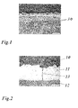
- Fig. 1 is a photograph showing the coarsening of the grain boundary 30 in a base metal at the origin of crack formation in a depletion zone.
- TBC thermal barrier coating
- Document EP 1 591 562 A2 discloses a structure comprising at least one metallic surface provided with cathodic protection and a protective coating for said surface, said coating comprising a polymer including micro-capsules containing compounds which are responsive to the electric field generated by the cathodic protection and which are capable of reacting in an alkaline medium to form a protective layer on the surface of the structure.
- the structures of the disclosure may, for example, be buried or submerged pipelines, reservoirs, boats or port or marine facilities.
- Document EP 1 743 957 A1 relates to a method for the treatment of the tip of a turbine blade.
- turbines which are used for example as engines for aeroplanes or as land based industrial gas turbines
- the tips of the turbine blades are provided with abrasive coatings, which make it possible for the tips of the turbine blades to cut their own way into the abradable seals when rotating, at least in the first hours of operation.
- the abrasive coatings usually contain hard grinding or cutting particles, which cut into the seal.
- the document proposes a method for the treatment of the blade tip of a turbine blade in which silicon carbide (SiC) particles are bound to the surface of a turbine blade for the production of an abrasive coating, with a self-healing barrier layer being produced on the SiC particles.
- SiC silicon carbide
- Document EP 1 840 245 relates to components for high temperature applications, for example turbine blades and combustion chamber walls of gas turbines, having protective layers against oxidation and corrosion.
- Such layers consist, for example, of an alloy of the MCrAIX type, a protective aluminum oxide layer being formed on this MCrAIX layer.
- the aluminum of the MCrAIX alloy diffuses onto the surface of the MCrAIX layer, so that the MCrAIX alloy undergoes a depletion of the element aluminum.
- a preventatively enhanced fraction of aluminum in the MCrAIX alloy from the outset, in order to counteract depletion leads to poorer mechanical properties of the MCrAIX layer.
- a matrix with particles for a component or a layer comprising a matrix material having at least one metal element, wherein the particles have either an oxide, a nitride, a boride, aluminum nitride or aluminum oxynitride, or wherein the compound of the particle has a Si-O-C-Me compound, and the metal element in the compound has a non-stoichiometric fraction.
- thermostructural composite materials comprising fibre reinforcement known as a fibre "preform" in which the fibres are made of a refractory material such as carbon or ceramic, and a matrix that fills in, at least in part, the pores initially present in the fibre reinforcement.
- a fibre "preform” in which the fibres are made of a refractory material such as carbon or ceramic
- a matrix that fills in, at least in part, the pores initially present in the fibre reinforcement.
- Such materials are known for their good mechanical properties, enabling them to be used as structural elements, and for their ability to conserve these properties at high temperatures, in particular when the matrix is made of ceramic.
- the document wants to improve the ability of a ceramic matrix thermostructural composite material having carbon or carbon-coated fibre reinforcement to withstand oxidation by sequencing the matrix so that cracking of the matrix can be retarded as much as possible.
- a matrix that is at least partially sequenced with alternating layers of relatively flexible anisotropic material capable of deflecting any cracks that reach them, and layers of relatively rigid ceramic material, said relatively flexible material having a rigidity less than that of the relatively rigid ceramic material.
- Each of a plurality of elementary sequences of the matrix comprises a relatively flexible layer of the relatively flexible anisotropic material and a relatively rigid ceramic layer, each of the plurality of elementary sequences having a thickness that increases going from the elementary sequence closest to the fibres to the elementary sequence furthest from the fibres, with at least the elementary sequence closest to the fibres coating them in substantially individual manner.
- the thickness of the relatively flexible layers of the relatively flexible anisotropic material, and the anisotropic character and the capacity for elastic deformation in shear and transversely of the material(s) constituting said layers are such that the matrix of the composite material is free from cracking, at least at the end of the process of building up the composite material.
- WO 2008/140479 A2 discloses a thermal barrier coating system, which includes a first layer of ceramic insulating material disposed on a substrate surface and a second layer of ceramic insulating material disposed on the first layer of ceramic insulating material.
- the second layer of ceramic insulating material includes one or more crack arrestors therein.
- a third layer of ceramic insulating material is disposed on the second layer of ceramic insulating material, which is configured as a sacrificial layer to absorb mechanical shock generated in the event of a foreign object collision with the third layer.
- the one or more crack arrestors in the second layer can avoid propagation towards the first layer of one or more cracks that can form in the event of the foreign object collision with the third layer.
- WO 2008/140481 A1 describes a thermal barrier coating system capable of self-healing, which has a substrate, a metal-based advanced bond coat overlying the substrate and a ceramic top coat overlying the bond coat.
- the bond coat comprises ceramic oxide precursor materials capable of forming a non-alumina ceramic oxide composition when exposed to a thermally conditioning oxidizing environment.
- Embodiments of such bond coat comprise rare earth elements in a range of 1-20 weight percent, and Hf in a range of about 5 to 30 weight percent or Zr in a range of about 2 to 20 weight percent.
- Examples of self-healing TBC systems are provided using such bond coat or its advanced bond coat chemistries in combination with conventional bond coats or conventional bond coat chemistries.
- a composite structure is disclosed in document WO 2009/127852 A1 , comprising: a first stack comprising a plurality of plies of composite material and at least one ply of self-healing material, the ply of self-healing material comprising a plurality of containers each containing a curable healing liquid; and a second stack comprising a plurality of plies of composite material, the stacks being joined together at a bond line.
- Document WO 2009/156376 A1 relates to a component with a self-healing surface layer or a self-healing enamel or a coating powder.
- the self-healing is guaranteed through a reactive substance that is encased inside of sheathed particles. Damage to the enamel layer leads to the destruction of the sheathing, preferably under the influence of a catalytic material, so that the encased fluid enamel can escape. Under the effect of UV light, the fluid enamel cures and closes the resultant crack.
- Document US 3 274 007 A discloses a high-temperature resistant coating with self-healing properties.
- the coating consists of a refractory oxide dry-mixed with silicon.
- the silicon has a considerable lower melting point and fills the voids in the refractory oxide.
- Document US 3 069 288 A describes a composite article comprising a solid substrate body and a corrosion resistant coating.
- the coating consist of an intermetallic compound of that substrate metal present as a porous matrix defining a capillary network, and an alloy located in said capillary network which is liquid at the temperature of use of that composite article.
- Document US 4 806 385 A discloses a method of producing oxidation resistant coatings for molybdenum by a step-wise application of a plurality of interbonded plasma-sprayed layers of a composite of molybdenum/refractory oxide material.
- Document WO 99/46338 A1 describes a self-healing system for a coating system for use at low temperatures.
- the coating system contains microcapsules which rupture and release fluid upon impact or other stress likely to damage the coating.
- the fluid form the microcapsules contains a film forming component to cover the damaged area of the coating.
- the present invention offers a new and different solution to the problems described in order to extend the lifetime and/or to reduce the reconditioning efforts and scrap rate for components in turbomachines.
- the inventive component is characterized in that the said active phase comprises one of Boron, Carbon, Phosphorous, Silicon or combinations thereof as a melting point depressant for reacting with the base material after a diffusion into the base material (15).
- said active phase has the form of individual particles, which are dispersed within the base material.
- said particles may be dispersed within the base material in a graded manner.
- said active phase has the form of fibres, which are incorporated into the base material.
- said fibres may be in a woven form.
- said particles and/or fibres each have a structure with a central core, which is enclosed by a shell.
- said central core and said shell are made of chemical substances in the form of ceramics or metals or combinations thereof.
- the chemical substances of the central core have the following characteristics:
- the chemical substances of the central core comprise one of Boron, Carbon, Phosphorous, Silicon, Nickel or a combination thereof, and react with the base material, thereby reducing the melting temperature.
- the chemical substances of the shell have the following characteristics:
- the chemical substances of the shell comprise Chrome, or Nickel, or Aluminium or a combination thereof.
- the self-healing system of the component further comprises an additional reservoir phase in order to balance the composition and achieve a constant optimum concentration of chemical substances within the component.
- the reservoir phase is in the form of individual particles, which are dispersed on top of and/or within the base material and each have a structure with a central core, which is enclosed by a shell.
- the core substances and/or the shell substances of the reservoir phase comprise Chrome, or Nickel, or Aluminium or a combination thereof.
- HVOF High Velocity Oxy Fuel
- APS Air Plasma Spraying
- SPS Suspension Plasma Spray
- the novelty of the present invention relates to the use of a self healing system for the base material, brazed regions and/or coatings of components based on the addition of melting point depressants for reacting with the base material according to the concept of the invention.
- the invention can be mitigation for crack formation and propagation due to (but not limited to it):
- the advantages of the invention comprise an increase of the lifetime, and/or a reduction of the reconditioning effort related to crack restoration and/or a decrease of the scrap rate and/or a decrease of the operation risk achieved by preventing cracks and/or slowing down crack propagation rate and/or healing the cracks.
- the invention has the technical goals of preventing crack formation and/or preventing crack propagation and/or curing/healing existing cracks.
- the invention is applicable to newly made and/or reconditioned components within turbomachines, preferably (but not only) gas turbine hot gas path blades and vanes, as well as heat shields and liners, or hot components of other engines.
- the invention focuses on metallic coatings on the whole component, coatings on a coupon, which is a part of a component but manufactured separately from the rest of the component.
- base materials the target components without a self healing system are referred to as "base materials”.
- the self healing system of the invention can be added completely, partially (for example only within the top surface) or on the top of the base materials. Furthermore, the self healing system of the invention can be added to the base material in a graded manner.
- the component according to the invention is the least one base material together with the active phase and optionally with the reservoir phase.
- the base material is around the active (and the reservoir) phase.
- the component can be for example a coating, a coupon, a braze joint or part of a vane, blade, liner etc.
- the self healing system comprises an active phase.
- this active phase has particles with potentially different shapes and/or fibers, which are optionally woven.
- the particles or fibers preferably have a core/shell structure.
- the core and shell can be made of chemical substances like non oxide or oxide ceramics, metals or combinations thereof.
- the chemical substances from the core may be solid at the operating temperature. They may react with the base material.
- the chemical substances of the shell have the following characteristics:
- an additional reservoir phase which may also have a core/shell structure, might be needed in order to balance the composition and achieve a constant optimal concentration of chemical substances (in particular the concentration of Chrome is important for the corrosion protection).
- the core substances can be so-called melting point depressants (MDP) like Boron, Carbon, Phosphorous, Silicon, Nickel or a combination thereof and the core may be of a material with a softening or melting temperature below or in the range of the operating temperature according to the invention.
- MDP melting point depressants
- the MDPs react with the base material in order to reduce the melting temperature. Materials with a softening or melting temperature below or in the range of the operating temperature preferably do not react with the base material.
- the shell substances of the active phase can be Chrome or Nickel or Aluminium or a combination thereof.
- the core substances can be Chrome or Nickel or Aluminium or a combination thereof.
- the shell substances of the reservoir phase can also be Chrome or Nickel or Aluminium or a combination thereof.
- the following method is applicable: For a coating with a self healing system the active phase and the bond coat particles, namely MCrAlY particles, are dispersed (mixture of both powders or suspension of both powders) and then sprayed with High Velocity Oxy Fuel (HVOF), a standard process to apply a bond coat, or Air Plasma Spray (APS), or Suspension Plasma Spray (SPS), or slurry coating or another process to apply a coating.
- HVOF High Velocity Oxy Fuel
- APS Air Plasma Spray
- SPS Suspension Plasma Spray
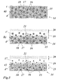
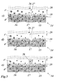
- Fig. 3(a)-(e) is related to the case or concept of prevention of crack formation by softening and damping:
- Fig. 3(a) shows the initial situation, i.e. at the installation of the component in the turbomachine.
- the component 14 comprises a base material 15, for example a metallic material, and contains dispersed particles 16 of an active phase, each of the particle 16 has a core 17 enclosed by a shell 18.
- the shell 18 has an initial shell thickness t.
- the core 17 has an initial core diameter d; however, the shape of the core can be non-spherical or arbitrary and d then means equivalent diameter of the core volume.
- oxidation of the surface of the component 14 results in a depletion zone 19 and an oxide layer 20.
- the gradient of concentration is the driving force for diffusion 21 of the chemical substances from the shell resulting in a thinner shell.
- the shell thickness after several hours of operation, t' is smaller than t (t' ⁇ t).
- the region of the depletion zone 19 shows the self healing effect:
- the base material 15 is softened enough in order to prevent crack formation or is healing a crack 24 simultaneously.
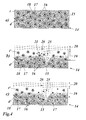
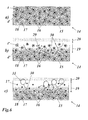
- Fig. 4(a)-(d) is related to the case or concept of prevention of large crack formation/propagation:
- Fig. 4(a) again shows the initial situation, i.e. at the installation of component in the turbomachine.
- the component 14 comprises a base material 15 and contains dispersed particles 16 of an active phase.
- Each of the particle 16 has a core 17 enclosed by a shell 18.
- the shell 18 has an initial shell thickness t.
- the core 17 has an initial core diameter d.
- Fig. 5(a)-(e) is related to the case or concept of fine crack healing:
- Fig. 5(a) again shows the initial situation, i.e. at the installation of the component in the turbomachine.
- the shell 18 has an initial shell thickness t.
- the core 17 has an initial core diameter d.
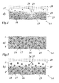
- Fig. 6(a)-(c) is related to the case or concept of crack prevention and crack healing:
- Fig. 6(a) again shows the initial situation, i.e. at the installation of the component in the turbomachine.
- the shell 18 has an initial shell thickness t.
- the core 17 has an initial core diameter d, meaning the equivalent diameter in case of arbitrary, non-spherical volume of the core.
- Fig. 7 is related to a concept, which can be additionally applied to the other concepts explained above. It shows the initial situation, i.e. at the installation of the component in the turbomachine.
- Fig. 8 is related to a concept of the control of crack propagation, wherein the base material 15 of the component 14' is reinforced with fibers 35.
- the role of the (preferably woven) fibers 35 is to mechanically stop the crack propagation and/or to orient them in directions of lower load. The stress peaks are redistributed in a more favorable direction.
- the fibers 35 may act as an active phase, as explained before.
Landscapes
- Chemical & Material Sciences (AREA)
- Engineering & Computer Science (AREA)
- Materials Engineering (AREA)
- Mechanical Engineering (AREA)
- Manufacturing & Machinery (AREA)
- Metallurgy (AREA)
- Organic Chemistry (AREA)
- Physics & Mathematics (AREA)
- Plasma & Fusion (AREA)
- Crystallography & Structural Chemistry (AREA)
- Chemical Kinetics & Catalysis (AREA)
- Turbine Rotor Nozzle Sealing (AREA)
Description
- The present invention relates to the technology of turbomachines. It refers to a component for a turbomachine according to the preamble of claim 1. It further refers to a method for manufacturing such a component.
- During service, the components in a turbomachine, in particular (but not only) gas turbine hot gas path components like heat shields, liners, blades and vanes, or hot components of other engines are subjected to high temperature, corrosive and oxidizing atmosphere and mechanical load. Due to these extreme conditions, the base metal, brazed regions and metallic coatings of components are prone to crack formation and propagation.
Fig. 1 is a photograph showing the coarsening of thegrain boundary 30 in a base metal at the origin of crack formation in a depletion zone.Fig. 2 is a photograph showing a thermo-mechanical fatigue crack 13, which is initiating in abond coat 11. Thecrack 13 propagates into base metal 12 (= substrate) and into a thermal barrier coating (TBC) 10. - Cracking is a limiting factor for the lifetime of a turbomachine component. In addition, the reconditioning efforts and the scrap rate are also highly dependent on the presence, size and location of cracks at the end of a service interval.
- Document
EP 1 591 562 A2 discloses a structure comprising at least one metallic surface provided with cathodic protection and a protective coating for said surface, said coating comprising a polymer including micro-capsules containing compounds which are responsive to the electric field generated by the cathodic protection and which are capable of reacting in an alkaline medium to form a protective layer on the surface of the structure. The structures of the disclosure may, for example, be buried or submerged pipelines, reservoirs, boats or port or marine facilities. - Document
EP 1 743 957 A1 relates to a method for the treatment of the tip of a turbine blade. In the operation of turbines which are used for example as engines for aeroplanes or as land based industrial gas turbines, it is desirable, from the point of view of efficiency to keep the clearance between the tips of the turbine blades and the corresponding seals in the housing as small as possible. For this reason, the tips of the turbine blades are provided with abrasive coatings, which make it possible for the tips of the turbine blades to cut their own way into the abradable seals when rotating, at least in the first hours of operation. The abrasive coatings usually contain hard grinding or cutting particles, which cut into the seal. It is known to embed these particles into an oxidation resistant metallic matrix, which is provided on the surface of the tip of the blade. The document proposes a method for the treatment of the blade tip of a turbine blade in which silicon carbide (SiC) particles are bound to the surface of a turbine blade for the production of an abrasive coating, with a self-healing barrier layer being produced on the SiC particles. - Document
EP 1 840 245 relates to components for high temperature applications, for example turbine blades and combustion chamber walls of gas turbines, having protective layers against oxidation and corrosion. Such layers consist, for example, of an alloy of the MCrAIX type, a protective aluminum oxide layer being formed on this MCrAIX layer. In this case, the aluminum of the MCrAIX alloy diffuses onto the surface of the MCrAIX layer, so that the MCrAIX alloy undergoes a depletion of the element aluminum. However, a preventatively enhanced fraction of aluminum in the MCrAIX alloy from the outset, in order to counteract depletion, leads to poorer mechanical properties of the MCrAIX layer. To have a longer protective action the document proposes to use a matrix with particles for a component or a layer, comprising a matrix material having at least one metal element, wherein the particles have either an oxide, a nitride, a boride, aluminum nitride or aluminum oxynitride, or wherein the compound of the particle has a Si-O-C-Me compound, and the metal element in the compound has a non-stoichiometric fraction. - Document
US 6,068,930 relates to thermostructural composite materials comprising fibre reinforcement known as a fibre "preform" in which the fibres are made of a refractory material such as carbon or ceramic, and a matrix that fills in, at least in part, the pores initially present in the fibre reinforcement. Such materials are known for their good mechanical properties, enabling them to be used as structural elements, and for their ability to conserve these properties at high temperatures, in particular when the matrix is made of ceramic. The document wants to improve the ability of a ceramic matrix thermostructural composite material having carbon or carbon-coated fibre reinforcement to withstand oxidation by sequencing the matrix so that cracking of the matrix can be retarded as much as possible. This is achieved by a matrix that is at least partially sequenced with alternating layers of relatively flexible anisotropic material capable of deflecting any cracks that reach them, and layers of relatively rigid ceramic material, said relatively flexible material having a rigidity less than that of the relatively rigid ceramic material. Each of a plurality of elementary sequences of the matrix comprises a relatively flexible layer of the relatively flexible anisotropic material and a relatively rigid ceramic layer, each of the plurality of elementary sequences having a thickness that increases going from the elementary sequence closest to the fibres to the elementary sequence furthest from the fibres, with at least the elementary sequence closest to the fibres coating them in substantially individual manner. The thickness of the relatively flexible layers of the relatively flexible anisotropic material, and the anisotropic character and the capacity for elastic deformation in shear and transversely of the material(s) constituting said layers are such that the matrix of the composite material is free from cracking, at least at the end of the process of building up the composite material. - Document
US 2002/0155316 A1 relates to composite MCrAIX-based coatings for superalloy substrates. To have a coating that possesses ductility to minimize crack propagation, while still preserving the necessary oxidation resistance conferred by the presence of an adequate amount of aluminum in the coating, the document proposes the use of composite coatings over a superalloy substrate that can significantly improve performance of parts fabricated there from. These composite MCrAIX coatings are designed to have a high aluminum concentration while retaining desired ductility. These coatings include a MCrAIX phase, and an aluminum-rich phase having an aluminum concentration higher than that of the MCrAIX phase, and including an aluminum diffusion-retarding composition. The aluminum rich phase supplies aluminum to the coating at about the same rate that aluminum is lost through oxidation, without significantly increasing or reducing the concentration of aluminum in the MCrAIX phase of the coating. The result is excellent oxidation resistance, without an increase in brittleness. - Document
WO 2008/140479 A2 discloses a thermal barrier coating system, which includes a first layer of ceramic insulating material disposed on a substrate surface and a second layer of ceramic insulating material disposed on the first layer of ceramic insulating material. The second layer of ceramic insulating material includes one or more crack arrestors therein. A third layer of ceramic insulating material is disposed on the second layer of ceramic insulating material, which is configured as a sacrificial layer to absorb mechanical shock generated in the event of a foreign object collision with the third layer. The one or more crack arrestors in the second layer can avoid propagation towards the first layer of one or more cracks that can form in the event of the foreign object collision with the third layer. - Document
WO 2008/140481 A1 describes a thermal barrier coating system capable of self-healing, which has a substrate, a metal-based advanced bond coat overlying the substrate and a ceramic top coat overlying the bond coat. The bond coat comprises ceramic oxide precursor materials capable of forming a non-alumina ceramic oxide composition when exposed to a thermally conditioning oxidizing environment. Embodiments of such bond coat comprise rare earth elements in a range of 1-20 weight percent, and Hf in a range of about 5 to 30 weight percent or Zr in a range of about 2 to 20 weight percent. Examples of self-healing TBC systems are provided using such bond coat or its advanced bond coat chemistries in combination with conventional bond coats or conventional bond coat chemistries. - A composite structure is disclosed in document
WO 2009/127852 A1 , comprising: a first stack comprising a plurality of plies of composite material and at least one ply of self-healing material, the ply of self-healing material comprising a plurality of containers each containing a curable healing liquid; and a second stack comprising a plurality of plies of composite material, the stacks being joined together at a bond line. By placing a ply of self-healing material in one of the stacks (preferably relatively close to the bond line) the ply of self-healing material can resist the propagation of cracks between the first stack and the second stack. - Document
WO 2009/156376 A1 relates to a component with a self-healing surface layer or a self-healing enamel or a coating powder. According to the disclosure, the self-healing is guaranteed through a reactive substance that is encased inside of sheathed particles. Damage to the enamel layer leads to the destruction of the sheathing, preferably under the influence of a catalytic material, so that the encased fluid enamel can escape. Under the effect of UV light, the fluid enamel cures and closes the resultant crack. - Document
US 2011/033721 A1 discloses a self healing alloy by incorporating of macro, micro or nanosize hollow reinforcements, filled with low melting healing material. The healing material melts and fills the cracks within a metallic matrix. - Document
US 3 274 007 A discloses a high-temperature resistant coating with self-healing properties. The coating consists of a refractory oxide dry-mixed with silicon. The silicon has a considerable lower melting point and fills the voids in the refractory oxide. - Document
US 3 069 288 A describes a composite article comprising a solid substrate body and a corrosion resistant coating. The coating consist of an intermetallic compound of that substrate metal present as a porous matrix defining a capillary network, and an alloy located in said capillary network which is liquid at the temperature of use of that composite article. - Document
US 4 806 385 A discloses a method of producing oxidation resistant coatings for molybdenum by a step-wise application of a plurality of interbonded plasma-sprayed layers of a composite of molybdenum/refractory oxide material. - Document
WO 99/46338 A1 - As shown above, some documents describe solutions to prevent crack formation or to stop the crack propagation or even to heal cracks during service.
- The present invention offers a new and different solution to the problems described in order to extend the lifetime and/or to reduce the reconditioning efforts and scrap rate for components in turbomachines.
- It is an object of the present invention to provide a component for a turbomachine or another engine containing a hot component, which substantially and effectively extends its lifetime with respect to crack formation, crack propagation and the healing of cracks.
- It is another object of the invention to provide methods for manufacturing such a component.
- This and other objects are obtained by a component according to claim 1 and a method according to
claim 15. - The component according to the invention, which is used in a turbomachine, in particular a gas turbine, or other engines containing hot components and which is prone to crack formation and propagation by being subjected to high temperatures and/or a corrosive and/or oxidising atmosphere and/or a high mechanical load and/or cyclic thermal load and/or transient conditions, contains a base material, which is a bond coat, made of MCrAlY with M= Fe or Ni or Co or combinations thereof. Said base material is provided with a self healing system in form of an added active phase. The inventive component is characterized in that the said active phase comprises one of Boron, Carbon, Phosphorous, Silicon or combinations thereof as a melting point depressant for reacting with the base material after a diffusion into the base material (15).
- According to one embodiment of the invention said active phase has the form of individual particles, which are dispersed within the base material.
- Particularly, said particles may be dispersed within the base material in a graded manner.
- According to another embodiment of the invention said active phase has the form of fibres, which are incorporated into the base material.
- Particularly, said fibres may be in a woven form.
- Preferably, said particles and/or fibres each have a structure with a central core, which is enclosed by a shell.
- In particular, said central core and said shell are made of chemical substances in the form of ceramics or metals or combinations thereof.
- Especially, the chemical substances of the central core have the following characteristics:
- a) decrease the melting point of the base material so that softening occurs at operating temperature;
- b) diffuse into the base material and/or optionally into the cracks;
- c) do not strongly oxidise when present at the surface in contact with oxygen;
- d) are able to chemically dissolve metal oxides;
- e) have a limited reactivity with Cr in order to avoid a decrease of the corrosion resistance.
- Preferably, the chemical substances of the central core comprise one of Boron, Carbon, Phosphorous, Silicon, Nickel or a combination thereof, and react with the base material, thereby reducing the melting temperature.
- Especially, the chemical substances of the shell have the following characteristics:
- a) diffuse slowly in order to liberate the core substances;
- b) do not react with the core substances;
- c) have a limited reactivity with Cr in order to avoid a decrease of the corrosion resistance.
- Preferably, the chemical substances of the shell comprise Chrome, or Nickel, or Aluminium or a combination thereof.
- According to another embodiment of the invention the self-healing system of the component further comprises an additional reservoir phase in order to balance the composition and achieve a constant optimum concentration of chemical substances within the component.
- In particular, the reservoir phase is in the form of individual particles, which are dispersed on top of and/or within the base material and each have a structure with a central core, which is enclosed by a shell.
- Preferably, the core substances and/or the shell substances of the reservoir phase comprise Chrome, or Nickel, or Aluminium or a combination thereof.
- A method for manufacturing a component according to the invention, which component has a bond coat as a base material, made of MCrAlY (M= Fe or Ni or Co or combinations thereof) and wherein said base materia is provided with a self healing system in form of an added active phase, is characterised in that, in a first step bond coat particles and particles of the active phase are dispersed, and in a second step the dispersed material is sprayed onto the component with a Thermal Spray process, especially a High Velocity Oxy Fuel (HVOF) process or an Air Plasma Spraying (APS) process or a Suspension Plasma Spray (SPS), or with a slurry coating process.
- The present invention is now to be explained more closely by means of different embodiments and with reference to the attached drawings.
- Fig. 1
- shows a photograph of the coarsening of the grain boundary at the origin of crack formation in a depletion zone of an exemplary turbomachine component;
- Fig. 2
- shows a photograph of thermo-mechanical fatigue crack initiated at the surface of a bond coat, which crack is propagating into both the ceramic layer and the base metal;
- Fig. 3
- shows different phases during the lifetime of a component with a healing system according to a first concept of the invention;
- Fig. 4
- shows different phases during the lifetime of a component with a healing system according to a second concept of the invention;
- Fig. 5
- shows different phases during the lifetime of a component with a healing system according to a third concept of the invention;
- Fig. 6
- shows different phases during the lifetime of a component with a healing system according to a fourth concept of the invention;
- Fig. 7
- shows an embodiment of the invention with an additional reservoir phase; and
- Fig. 8
- shows an embodiment of the invention, where fibres are used as a crack stopping means.
- The novelty of the present invention relates to the use of a self healing system for the base material, brazed regions and/or coatings of components based on the addition of melting point depressants for reacting with the base material according to the concept of the invention. The invention can be mitigation for crack formation and propagation due to (but not limited to it):
- corrosion
- and/or oxidation
- and/or grain boundary coarsening due to precipitation
- and/or creep
- and/or low cycle fatigue
- and/or high cycle fatigue
- and/or thermal mechanical fatigue.
- It can also heal the cracks already formed.
- The advantages of the invention comprise an increase of the lifetime, and/or a reduction of the reconditioning effort related to crack restoration and/or a decrease of the scrap rate and/or a decrease of the operation risk achieved by preventing cracks and/or slowing down crack propagation rate and/or healing the cracks.
- In general, the invention has the technical goals of preventing crack formation and/or preventing crack propagation and/or curing/healing existing cracks.
- The invention is applicable to newly made and/or reconditioned components within turbomachines, preferably (but not only) gas turbine hot gas path blades and vanes, as well as heat shields and liners, or hot components of other engines. The invention focuses on metallic coatings on the whole component, coatings on a coupon, which is a part of a component but manufactured separately from the rest of the component.
- In the explanations given below, the target components without a self healing system are referred to as "base materials".
- The self healing system of the invention can be added completely, partially (for example only within the top surface) or on the top of the base materials. Furthermore, the self healing system of the invention can be added to the base material in a graded manner.
- The component according to the invention is the least one base material together with the active phase and optionally with the reservoir phase. The base material is around the active (and the reservoir) phase. The component can be for example a coating, a coupon, a braze joint or part of a vane, blade, liner etc.
- According to the invention, the self healing system comprises an active phase. In particular, this active phase has particles with potentially different shapes and/or fibers, which are optionally woven. The particles or fibers preferably have a core/shell structure. The core and shell can be made of chemical substances like non oxide or oxide ceramics, metals or combinations thereof.
- The chemical substances of the core have preferably the following characteristics:
- a) decrease the melting point of the base material so that softening occurs at operating temperature;
- b) diffuse into the base material and/or optionally into the cracks;
- c) do not strongly oxidize when present at the surface in contact with oxygen;
- d) are able to chemically dissolve the metal oxides;
- e) have a limited reactivity with Cr in order to avoid a decrease of the corrosion resistance.
- Furthermore, the chemical substances from the core may be solid at the operating temperature. They may react with the base material.
- The chemical substances of the shell, on the other hand, have the following characteristics:
- a) diffuse slowly in order to liberate the core substances;
- b) do not react with the core substances; and
- c) have a limited reactivity with Cr in order to avoid a decrease of the corrosion resistance.
- Optionally, an additional reservoir phase, which may also have a core/shell structure, might be needed in order to balance the composition and achieve a constant optimal concentration of chemical substances (in particular the concentration of Chrome is important for the corrosion protection).
- For the active phase with its core/shell structure, the core substances can be so-called melting point depressants (MDP) like Boron, Carbon, Phosphorous, Silicon, Nickel or a combination thereof and the core may be of a material with a softening or melting temperature below or in the range of the operating temperature according to the invention.
- The MDPs react with the base material in order to reduce the melting temperature. Materials with a softening or melting temperature below or in the range of the operating temperature preferably do not react with the base material.
- The shell substances of the active phase can be Chrome or Nickel or Aluminium or a combination thereof.
- For the above-mentioned reservoir phase the core substances can be Chrome or Nickel or Aluminium or a combination thereof.
- The shell substances of the reservoir phase can also be Chrome or Nickel or Aluminium or a combination thereof.
- For the processing of the base material with the self healing system, the following method is applicable: For a coating with a self healing system the active phase and the bond coat particles, namely MCrAlY particles, are dispersed (mixture of both powders or suspension of both powders) and then sprayed with High Velocity Oxy Fuel (HVOF), a standard process to apply a bond coat, or Air Plasma Spray (APS), or Suspension Plasma Spray (SPS), or slurry coating or another process to apply a coating.
- Within the scope of the invention, there are many more alternatives for processing base material with self healing system according to the invention.
- With respect to
Fig. 3 to 8 , various concepts of the base material plus healing system according to the invention will be explained. -
Fig. 3(a)-(e) is related to the case or concept of prevention of crack formation by softening and damping: -
Fig. 3(a) shows the initial situation, i.e. at the installation of the component in the turbomachine. Thecomponent 14 comprises abase material 15, for example a metallic material, and contains dispersedparticles 16 of an active phase, each of theparticle 16 has a core 17 enclosed by ashell 18. Theshell 18 has an initial shell thickness t. Thecore 17 has an initial core diameter d; however, the shape of the core can be non-spherical or arbitrary and d then means equivalent diameter of the core volume. - After several hours of operation (
Fig. 3(b) ) oxidation of the surface of thecomponent 14 results in adepletion zone 19 and anoxide layer 20. The gradient of concentration is the driving force fordiffusion 21 of the chemical substances from the shell resulting in a thinner shell. The shell thickness after several hours of operation, t', is smaller than t (t' < t). The core diameter after several hours of operation, d', is equal to d (d' = d). - After several additional hours of operation (
Fig. 3(c) ) all the shell substances are dissolved into thebase material 15. Now, the core substance is liberated bydiffusion 22. Thebase material 15 becomes softer (incipient melting) or locally liquid at the service temperature. One (among several others) mechanism for crack prevention is a damping effect for vibrations produced by viscous dissipation properties of the liquated material. The core diameter, d", is smaller than d'. There is anextension 23 of thedepletion zone 19. - After several additional hours of operation (
Fig. 3(d) ) the region of thedepletion zone 19 shows the self healing effect: Thebase material 15 is softened enough in order to prevent crack formation or is healing acrack 24 simultaneously. - At the end of the lifetime of the component 14 (
Fig. 3(e) ) the effect is extended together with theextension 23 of thedepletion zone 19. Self-maintenance of the process is established by consumption of the surface (oxide layer 20) and propagation of thedepletion zone 19. -
Fig. 4(a)-(d) is related to the case or concept of prevention of large crack formation/propagation: -
Fig. 4(a) again shows the initial situation, i.e. at the installation of component in the turbomachine. Thecomponent 14 comprises abase material 15 and contains dispersedparticles 16 of an active phase. Each of theparticle 16 has a core 17 enclosed by ashell 18. Theshell 18 has an initial shell thickness t. Thecore 17 has an initial core diameter d. - After several hours of operation (
Fig. 4(b) ) there is the formation oflarge cracks 25 in thebase material 15. The oxidation of the crack surface results in a crack-relateddepletion zone 26. The gradient of concentration in themain depletion zone 19 is the driving force fordiffusion 21 of the chemical substances contained in theshell 18 resulting in a thinner shell. - After several additional hours of operation (
Fig. 4(c) ) the chemical substances from the core 17 are liberated resulting in a softening or a melting point reduction within the depletedarea 19. Propagation of thecracks 25 is stopped or at least slowed down. - At the end of the lifetime (
Fig. 4(d) ) self-maintenance of the process is established by consumption of the surface (oxide layer 20) and propagation of the depletion zone 19 (extension 23). -
Fig. 5(a)-(e) is related to the case or concept of fine crack healing: -
Fig. 5(a) again shows the initial situation, i.e. at the installation of the component in the turbomachine. Thecomponent 14, which comprises abase material 15, contains dispersedparticles 16, each of which has a core 17 enclosed by ashell 18. Theshell 18 has an initial shell thickness t. Thecore 17 has an initial core diameter d. - After several hours of operation (
Fig. 5(b) ) there is a formation of fine cracks 27. In addition, anoxide layer 20 and first andsecond depletion zones - Then, after several additional hours of operation (
Fig. 5(c) ) a diffusion of substances from theshell 18 takes place. - After several additional hours of operation (
Fig. 5(d) ) there is a dissolution of metal oxides, which might have formed in thecrack 27, by the liberation of the substance from thecore 17. - After several additional hours of operation (
Fig. 5(e) ) there is a softening and/or melting due to the liberation of the core substances and/or liberation of liquid substances. There is a filling 28 of the crack and local re-oxidation at the initial crack position. -
Fig. 6(a)-(c) is related to the case or concept of crack prevention and crack healing: -
Fig. 6(a) again shows the initial situation, i.e. at the installation of the component in the turbomachine. Thecomponent 14, which comprises abase material 15, contains dispersedparticles 16, each of which has a core 17 enclosed by ashell 18. Theshell 18 has an initial shell thickness t. Thecore 17 has an initial core diameter d, meaning the equivalent diameter in case of arbitrary, non-spherical volume of the core. - After several hours of operation (
Fig. 6(b) ) anoxide layer 20 and adepletion zone 19 are formed. Furthermore, there is a coarsening of thegrain boundaries 30 by precipitation in thebase material 15. At the same time,diffusion 29 from theshell 18 takes place. - After several additional hours of operation (
Fig. 6(c) ) cracks tend to form in the prolongation of the coarsened grain boundaries 30 (crack formation zone 31). Cracks are avoided or simultaneously self healed. -
Fig. 7 is related to a concept, which can be additionally applied to the other concepts explained above. It shows the initial situation, i.e. at the installation of the component in the turbomachine. Thecomponent 14, which comprises abase material 15, contains dispersedparticles 16, each of which has a core 17 enclosed by ashell 18. Further to the active phase (particles 16) there is dispersed a reservoirphase comprising particles 32 with a core/shell structure withcore 33 andshell 34. - Finally,
Fig. 8 is related to a concept of the control of crack propagation, wherein thebase material 15 of the component 14' is reinforced withfibers 35. - The role of the (preferably woven)
fibers 35 is to mechanically stop the crack propagation and/or to orient them in directions of lower load. The stress peaks are redistributed in a more favorable direction. Thefibers 35 may act as an active phase, as explained before. -
- 10
- thermal barrier coating (TBC)
- 11
- bond coat
- 12
- base metal (substrate)
- 13
- crack
- 14,14'
- component
- 15
- base material
- 16
- particle (active phase)
- 17,33
- core
- 18,34
- shell
- 19,26
- depletion zone
- 20
- oxide layer
- 21,29
- shell diffusion
- 22
- core diffusion
- 23
- extension (depletion zone)
- 24,25,27
- crack
- 28
- filling
- 30
- grain boundary
- 31
- crack formation zone
- 32
- particle (reservoir phase)
- 35
- fibre (active phase)
- d,d',d"
- core diameter (or equivalent diameter in case of arbitrary, non-spherical volume)
- t,t',t"
- shell thickness (or equivalent thickness in case of arbitrary, non-spherical volume)
Claims (15)
- Component for a turbomachine, in particular a gas turbine, or another engine containing a hot component, which component (14, 14') is prone to crack formation and propagation by being subjected to high temperatures and/or a corrosive and/or oxidising atmosphere and/or a high mechanical load and/or cyclic thermal load and/or transient conditions, whereby said component (14, 14') having a bond coat, made of MCrAlY with M= Fe or Ni or Co or combinations thereof; as a base material (15), wherein said base material (15) is provided with a self healing system in form of an added active phase (16, 35), characterized in that said active phase (16, 35) comprises one of Boron, Carbon, Phosphorous, Silicon or combinations thereof as a melting point depressant for reacting with the base material (15) after a diffusion into the base material (15).
- Component according to claim 1, characterised in that said active phase has the form of individual particles (16), which are dispersed within the base material (15).
- Component according to claim 2, characterised in that said particles (16) are dispersed within the base material (15) in a graded manner.
- Component according to claim 1, characterised in that said active phase has the form of fibres (35), which are incorporated into the base material (15).
- Component according to claim 4, characterised in that said fibres (35) are in a woven form.
- Component according to one of the claims 2 to 5, characterised in that said particles (16) and/or fibres (35) each have a structure with a central core (17), which is enclosed by a shell (18).
- Component according to claim 6, characterised in that said central core (17) and said shell (18) are made of chemical substances in the form of ceramics or metals or combinations thereof.
- Component according to claim 7, characterised in that the chemical substances of the central core (17) have the following characteristics:a) decrease the melting point of the base material so that softening occurs;b) diffuse into the base material (15) and/or optionally into the cracks;c) do not strongly oxidize when present at the surface in contact with oxygen;d) are able to chemically dissolve metal oxides;e) have a limited reactivity with Cr in order to avoid a decrease of the corrosion resistance.
- Component according to claim 8, characterised in that the chemical substances of the central core (17) comprise one of Boron, Carbon, Phosphorous, Silicon, Nickel or a combination thereof, and react with the base material (15), thereby reducing the melting temperature.
- Component according to claim 7, characterised in that the chemical substances of the shell (18) have the following characteristics:a) diffuse slowly in order to liberate the core substances;b) do not react with the core substances,c) have a limited reactivity with Cr in order to avoid a decrease of the corrosion resistance.
- Component according to claim 10, characterised in that the chemical substances of the shell (18) comprise Chrome, or Nickel, or Aluminium or a combination thereof.
- Component according to one of the claims 1 to 11, characterised in that the self-healing system further comprises an additional reservoir phase (32) in
order to balance the composition and achieve a constant optimum concentration of chemical substances within the component (14, 14'). - Component according to claim 12, characterised in that the reservoir phase is in the form individual particles (32), which are dispersed on top of and/or within the base material (15) and each have a structure with a central core (33), which is enclosed by a shell (34).
- Component according to claim 13, characterised in that the core substances and/or the shell substances of the reservoir phase comprise Chrome, Nickel, or Aluminium, or a combination thereof.
- Method for manufacturing a component according to one of the claims 1 to 14, said component having a bond coat, made of MCrAlY with M= Fe or Ni or Co or combinations thereof as a base material (15), wherein said base material (15) is provided with a self healing system in form of an added active phase (16, 35) characterised in that, in a first step bond coat particles (base material 15) and particles of the active phase (16, 35) are dispersed, and in a second step the dispersed material is sprayed onto the component with a Thermal Spray, or a Suspension Plasma Spray (SPS), or a slurry coating process.
Applications Claiming Priority (1)
| Application Number | Priority Date | Filing Date | Title |
|---|---|---|---|
| CH00604/11A CH704833A1 (en) | 2011-04-04 | 2011-04-04 | Component for a turbo machine and a method of manufacturing such a component. |
Publications (2)
| Publication Number | Publication Date |
|---|---|
| EP2508648A1 EP2508648A1 (en) | 2012-10-10 |
| EP2508648B1 true EP2508648B1 (en) | 2015-01-14 |
Family
ID=44168187
Family Applications (1)
| Application Number | Title | Priority Date | Filing Date |
|---|---|---|---|
| EP20120163023 Not-in-force EP2508648B1 (en) | 2011-04-04 | 2012-04-03 | Component for a turbomachine and method for manufacturing such a component |
Country Status (5)
| Country | Link |
|---|---|
| US (1) | US20120251777A1 (en) |
| EP (1) | EP2508648B1 (en) |
| CA (1) | CA2772227C (en) |
| CH (1) | CH704833A1 (en) |
| IN (1) | IN2012DE01024A (en) |
Families Citing this family (17)
| Publication number | Priority date | Publication date | Assignee | Title |
|---|---|---|---|---|
| US9435014B2 (en) * | 2009-08-07 | 2016-09-06 | Pradeep Kumar Rohatgi | Self-healing aluminum alloys incorporating shape metal alloys and reactive particles |
| EP2647795B1 (en) * | 2012-04-04 | 2018-11-07 | MTU Aero Engines AG | Seal system for a turbo engine |
| EP2781691A1 (en) | 2013-03-19 | 2014-09-24 | Alstom Technology Ltd | Method for reconditioning a hot gas path part of a gas turbine |
| EP3060693B1 (en) | 2013-10-25 | 2018-06-27 | United Technologies Corporation | Plasma spraying system with adjustable coating medium nozzle |
| US9511436B2 (en) | 2013-11-08 | 2016-12-06 | General Electric Company | Composite composition for turbine blade tips, related articles, and methods |
| WO2016003627A2 (en) * | 2014-06-12 | 2016-01-07 | University Of Florida Research Foundation, Inc. | Self-repairing metal alloy matrix composites, methods of manufacture and use thereof and articles comprising the same |
| DE102014222686A1 (en) * | 2014-11-06 | 2016-05-12 | Siemens Aktiengesellschaft | Double-layered thermal barrier coating by different coating methods |
| US10316413B2 (en) * | 2015-08-18 | 2019-06-11 | Baker Hughes, A Ge Company, Llc | Self-healing coatings for oil and gas applications |
| DE102015216749A1 (en) * | 2015-09-02 | 2017-03-02 | Siemens Aktiengesellschaft | Additive production of a molded article |
| EP3345695A1 (en) | 2017-01-05 | 2018-07-11 | Fundación Tecnalia Research & Innovation | Method for obtaining a part with self-healing properties, part with self-healing properties and method for repairing cracks of the part |
| WO2018160195A1 (en) * | 2017-03-03 | 2018-09-07 | Siemens Aktiengesellschaft | Protective oxide coating for a thermal barrier coating formed from particles having a metal oxide core and an oxidizable metal shell |
| EP3873691B1 (en) | 2018-10-29 | 2023-07-26 | Cartridge Limited | Thermally enhanced exhaust port liner |
| EP3663706B1 (en) * | 2018-12-06 | 2022-08-24 | General Electric Company | Quantitative multilayer assessment method |
| IT201900003691A1 (en) * | 2019-03-13 | 2020-09-13 | Nuovo Pignone Tecnologie Srl | Abrasive terminal of a rotor blade for a turboexpander |
| CN110303154B (en) * | 2019-06-13 | 2021-07-30 | 北京工业大学 | Gradient brazing filler metal layer preparation and integrated brazing process based on laser fused deposition additive manufacturing technology |
| FR3106512B1 (en) * | 2020-01-23 | 2022-06-17 | Thales Sa | Process for manufacturing a multi-material part by additive manufacturing, using the technique of selective melting or selective laser powder bed sintering |
| US11686208B2 (en) | 2020-02-06 | 2023-06-27 | Rolls-Royce Corporation | Abrasive coating for high-temperature mechanical systems |
Family Cites Families (18)
| Publication number | Priority date | Publication date | Assignee | Title |
|---|---|---|---|---|
| US3069288A (en) * | 1959-08-06 | 1962-12-18 | Gen Electric | Self-repairing coatings for metal |
| US3274007A (en) * | 1963-08-01 | 1966-09-20 | Lockheed Aircraft Corp | High-temperature resistant self-healing coating and method of application |
| US4806385A (en) * | 1987-03-24 | 1989-02-21 | Amax Inc. | Method of producing oxidation resistant coatings for molybdenum |
| US4745033A (en) * | 1987-03-24 | 1988-05-17 | Amax Inc. | Oxidation resistant coatings for molybdenum |
| US5561173A (en) * | 1990-06-19 | 1996-10-01 | Carolyn M. Dry | Self-repairing, reinforced matrix materials |
| FR2742433B1 (en) | 1995-12-14 | 1998-03-13 | Europ Propulsion | THERMOSTRUCTURAL COMPOSITE MATERIALS WITH CARBON FIBER REINFORCEMENTS OR CARBON COATED, HAVING INCREASED OXIDATION RESISTANCE |
| US6075072A (en) * | 1998-03-13 | 2000-06-13 | 3M Innovative Properties Company | Latent coating for metal surface repair |
| US6635362B2 (en) * | 2001-02-16 | 2003-10-21 | Xiaoci Maggie Zheng | High temperature coatings for gas turbines |
| FR2869624B1 (en) | 2004-04-28 | 2006-06-09 | Inst Francais Du Petrole | SELF-REPAIRING STRUCTURE AND COATING FOR A CORROSIVE ENVIRONMENT |
| EP1707650A1 (en) * | 2005-03-31 | 2006-10-04 | Siemens Aktiengesellschaft | Matrix and coating system |
| EP1743957A1 (en) | 2005-07-14 | 2007-01-17 | Sulzer Metco (US) Inc. | Process for treating the tip of a turbine blade and turbine blade treated by such a process |
| EP1840245A1 (en) | 2006-03-27 | 2007-10-03 | Siemens Aktiengesellschaft | Matrix and coating system comprising non-stochiometric particles |
| US7507484B2 (en) | 2006-12-01 | 2009-03-24 | Siemens Energy, Inc. | Bond coat compositions and arrangements of same capable of self healing |
| US8021742B2 (en) | 2006-12-15 | 2011-09-20 | Siemens Energy, Inc. | Impact resistant thermal barrier coating system |
| GB0806921D0 (en) | 2008-04-16 | 2008-05-21 | Airbus Uk Ltd | Composite laminate with self-healing layer |
| DE102008030189A1 (en) * | 2008-06-25 | 2009-12-31 | Siemens Aktiengesellschaft | Component with a self-healing surface layer, self-healing lacquer or coating powder with self-healing properties |
| DE102008060923B4 (en) * | 2008-12-06 | 2012-09-27 | Innovent E.V. | Use of a layer |
| US8518531B2 (en) * | 2009-08-07 | 2013-08-27 | Pradeep K. Rohatgi | Self healing metals and alloys—including structural alloys and self-healing solders |
-
2011
- 2011-04-04 CH CH00604/11A patent/CH704833A1/en not_active Application Discontinuation
-
2012
- 2012-03-19 CA CA2772227A patent/CA2772227C/en not_active Expired - Fee Related
- 2012-03-21 US US13/425,658 patent/US20120251777A1/en not_active Abandoned
- 2012-04-03 EP EP20120163023 patent/EP2508648B1/en not_active Not-in-force
- 2012-04-03 IN IN1024DE2012 patent/IN2012DE01024A/en unknown
Also Published As
| Publication number | Publication date |
|---|---|
| CH704833A1 (en) | 2012-10-15 |
| EP2508648A1 (en) | 2012-10-10 |
| CA2772227A1 (en) | 2012-10-04 |
| IN2012DE01024A (en) | 2015-07-24 |
| CA2772227C (en) | 2017-02-21 |
| US20120251777A1 (en) | 2012-10-04 |
Similar Documents
| Publication | Publication Date | Title |
|---|---|---|
| EP2508648B1 (en) | Component for a turbomachine and method for manufacturing such a component | |
| EP2615250B1 (en) | Continuous fiber reinforced mesh bond coat for environmental barrier coating system | |
| EP2971533B1 (en) | Turbine blade tip treatment for industrial gas turbines | |
| EP2893148B1 (en) | Thermal barrier coating for gas turbine engine components | |
| US7887929B2 (en) | Oriented fiber ceramic matrix composite abradable thermal barrier coating | |
| EP2009141B1 (en) | Thermal barrier system and bonding method | |
| EP2537822B1 (en) | Composite article including layer comprising silicon oxycarbide | |
| CN110770416B (en) | Coated turbine component and associated production method | |
| EP2492445B1 (en) | Protective coatings and coated components comprising the protective coatings | |
| EP2014784B1 (en) | Thermal barrier coating system for thermal mechanical fatigue resistance | |
| JP7232295B2 (en) | Adhesion-promoting layer for bonding high-temperature protective layer onto substrate, and method for producing same | |
| KR101681195B1 (en) | Thermal Barrier Coating System with Self-Healing Ability | |
| US11473432B2 (en) | Anti-CMAS coating with enhanced efficiency | |
| EP2636763B1 (en) | Method for applying a high-temperature stable coating layer on the surface of a component and component with such a coating layer | |
| US10414694B2 (en) | Toughened bond layer and method of production | |
| CN114502773B (en) | Coated component comprising a MAX phase based protective coating | |
| EP3033494A1 (en) | A component for a turbomachine and a method for construction of the component | |
| TW201302348A (en) | Component for a turbomachine and method for manufacturing such a component | |
| EP3901416A1 (en) | Process and material configuration for making hot corrosion resistant hpc abrasive blade tips |
Legal Events
| Date | Code | Title | Description |
|---|---|---|---|
| PUAI | Public reference made under article 153(3) epc to a published international application that has entered the european phase |
Free format text: ORIGINAL CODE: 0009012 |
|
| AK | Designated contracting states |
Kind code of ref document: A1 Designated state(s): AL AT BE BG CH CY CZ DE DK EE ES FI FR GB GR HR HU IE IS IT LI LT LU LV MC MK MT NL NO PL PT RO RS SE SI SK SM TR |
|
| AX | Request for extension of the european patent |
Extension state: BA ME |
|
| 17P | Request for examination filed |
Effective date: 20130409 |
|
| 17Q | First examination report despatched |
Effective date: 20131118 |
|
| GRAP | Despatch of communication of intention to grant a patent |
Free format text: ORIGINAL CODE: EPIDOSNIGR1 |
|
| INTG | Intention to grant announced |
Effective date: 20140923 |
|
| GRAS | Grant fee paid |
Free format text: ORIGINAL CODE: EPIDOSNIGR3 |
|
| GRAA | (expected) grant |
Free format text: ORIGINAL CODE: 0009210 |
|
| AK | Designated contracting states |
Kind code of ref document: B1 Designated state(s): AL AT BE BG CH CY CZ DE DK EE ES FI FR GB GR HR HU IE IS IT LI LT LU LV MC MK MT NL NO PL PT RO RS SE SI SK SM TR |
|
| REG | Reference to a national code |
Ref country code: GB Ref legal event code: FG4D |
|
| REG | Reference to a national code |
Ref country code: CH Ref legal event code: EP |
|
| REG | Reference to a national code |
Ref country code: IE Ref legal event code: FG4D |
|
| REG | Reference to a national code |
Ref country code: AT Ref legal event code: REF Ref document number: 707121 Country of ref document: AT Kind code of ref document: T Effective date: 20150215 |
|
| REG | Reference to a national code |
Ref country code: DE Ref legal event code: R096 Ref document number: 602012004867 Country of ref document: DE Effective date: 20150305 |
|
| REG | Reference to a national code |
Ref country code: NL Ref legal event code: T3 |
|
| REG | Reference to a national code |
Ref country code: AT Ref legal event code: MK05 Ref document number: 707121 Country of ref document: AT Kind code of ref document: T Effective date: 20150114 |
|
| REG | Reference to a national code |
Ref country code: LT Ref legal event code: MG4D |
|
| PG25 | Lapsed in a contracting state [announced via postgrant information from national office to epo] |
Ref country code: LT Free format text: LAPSE BECAUSE OF FAILURE TO SUBMIT A TRANSLATION OF THE DESCRIPTION OR TO PAY THE FEE WITHIN THE PRESCRIBED TIME-LIMIT Effective date: 20150114 Ref country code: NO Free format text: LAPSE BECAUSE OF FAILURE TO SUBMIT A TRANSLATION OF THE DESCRIPTION OR TO PAY THE FEE WITHIN THE PRESCRIBED TIME-LIMIT Effective date: 20150414 Ref country code: ES Free format text: LAPSE BECAUSE OF FAILURE TO SUBMIT A TRANSLATION OF THE DESCRIPTION OR TO PAY THE FEE WITHIN THE PRESCRIBED TIME-LIMIT Effective date: 20150114 Ref country code: FI Free format text: LAPSE BECAUSE OF FAILURE TO SUBMIT A TRANSLATION OF THE DESCRIPTION OR TO PAY THE FEE WITHIN THE PRESCRIBED TIME-LIMIT Effective date: 20150114 Ref country code: HR Free format text: LAPSE BECAUSE OF FAILURE TO SUBMIT A TRANSLATION OF THE DESCRIPTION OR TO PAY THE FEE WITHIN THE PRESCRIBED TIME-LIMIT Effective date: 20150114 Ref country code: SE Free format text: LAPSE BECAUSE OF FAILURE TO SUBMIT A TRANSLATION OF THE DESCRIPTION OR TO PAY THE FEE WITHIN THE PRESCRIBED TIME-LIMIT Effective date: 20150114 Ref country code: BG Free format text: LAPSE BECAUSE OF FAILURE TO SUBMIT A TRANSLATION OF THE DESCRIPTION OR TO PAY THE FEE WITHIN THE PRESCRIBED TIME-LIMIT Effective date: 20150414 |
|
| PG25 | Lapsed in a contracting state [announced via postgrant information from national office to epo] |
Ref country code: GR Free format text: LAPSE BECAUSE OF FAILURE TO SUBMIT A TRANSLATION OF THE DESCRIPTION OR TO PAY THE FEE WITHIN THE PRESCRIBED TIME-LIMIT Effective date: 20150415 Ref country code: RS Free format text: LAPSE BECAUSE OF FAILURE TO SUBMIT A TRANSLATION OF THE DESCRIPTION OR TO PAY THE FEE WITHIN THE PRESCRIBED TIME-LIMIT Effective date: 20150114 Ref country code: LV Free format text: LAPSE BECAUSE OF FAILURE TO SUBMIT A TRANSLATION OF THE DESCRIPTION OR TO PAY THE FEE WITHIN THE PRESCRIBED TIME-LIMIT Effective date: 20150114 Ref country code: PL Free format text: LAPSE BECAUSE OF FAILURE TO SUBMIT A TRANSLATION OF THE DESCRIPTION OR TO PAY THE FEE WITHIN THE PRESCRIBED TIME-LIMIT Effective date: 20150114 Ref country code: IS Free format text: LAPSE BECAUSE OF FAILURE TO SUBMIT A TRANSLATION OF THE DESCRIPTION OR TO PAY THE FEE WITHIN THE PRESCRIBED TIME-LIMIT Effective date: 20150514 Ref country code: AT Free format text: LAPSE BECAUSE OF FAILURE TO SUBMIT A TRANSLATION OF THE DESCRIPTION OR TO PAY THE FEE WITHIN THE PRESCRIBED TIME-LIMIT Effective date: 20150114 |
|
| REG | Reference to a national code |
Ref country code: DE Ref legal event code: R097 Ref document number: 602012004867 Country of ref document: DE |
|
| PG25 | Lapsed in a contracting state [announced via postgrant information from national office to epo] |
Ref country code: EE Free format text: LAPSE BECAUSE OF FAILURE TO SUBMIT A TRANSLATION OF THE DESCRIPTION OR TO PAY THE FEE WITHIN THE PRESCRIBED TIME-LIMIT Effective date: 20150114 Ref country code: RO Free format text: LAPSE BECAUSE OF FAILURE TO SUBMIT A TRANSLATION OF THE DESCRIPTION OR TO PAY THE FEE WITHIN THE PRESCRIBED TIME-LIMIT Effective date: 20150114 Ref country code: DK Free format text: LAPSE BECAUSE OF FAILURE TO SUBMIT A TRANSLATION OF THE DESCRIPTION OR TO PAY THE FEE WITHIN THE PRESCRIBED TIME-LIMIT Effective date: 20150114 Ref country code: SK Free format text: LAPSE BECAUSE OF FAILURE TO SUBMIT A TRANSLATION OF THE DESCRIPTION OR TO PAY THE FEE WITHIN THE PRESCRIBED TIME-LIMIT Effective date: 20150114 Ref country code: CZ Free format text: LAPSE BECAUSE OF FAILURE TO SUBMIT A TRANSLATION OF THE DESCRIPTION OR TO PAY THE FEE WITHIN THE PRESCRIBED TIME-LIMIT Effective date: 20150114 |
|
| PLBE | No opposition filed within time limit |
Free format text: ORIGINAL CODE: 0009261 |
|
| STAA | Information on the status of an ep patent application or granted ep patent |
Free format text: STATUS: NO OPPOSITION FILED WITHIN TIME LIMIT |
|
| PG25 | Lapsed in a contracting state [announced via postgrant information from national office to epo] |
Ref country code: LU Free format text: LAPSE BECAUSE OF FAILURE TO SUBMIT A TRANSLATION OF THE DESCRIPTION OR TO PAY THE FEE WITHIN THE PRESCRIBED TIME-LIMIT Effective date: 20150403 Ref country code: MC Free format text: LAPSE BECAUSE OF FAILURE TO SUBMIT A TRANSLATION OF THE DESCRIPTION OR TO PAY THE FEE WITHIN THE PRESCRIBED TIME-LIMIT Effective date: 20150114 |
|
| 26N | No opposition filed |
Effective date: 20151015 |
|
| REG | Reference to a national code |
Ref country code: IE Ref legal event code: MM4A |
|
| REG | Reference to a national code |
Ref country code: FR Ref legal event code: ST Effective date: 20151231 |
|
| PG25 | Lapsed in a contracting state [announced via postgrant information from national office to epo] |
Ref country code: SI Free format text: LAPSE BECAUSE OF FAILURE TO SUBMIT A TRANSLATION OF THE DESCRIPTION OR TO PAY THE FEE WITHIN THE PRESCRIBED TIME-LIMIT Effective date: 20150114 Ref country code: FR Free format text: LAPSE BECAUSE OF NON-PAYMENT OF DUE FEES Effective date: 20150430 |
|
| PG25 | Lapsed in a contracting state [announced via postgrant information from national office to epo] |
Ref country code: IE Free format text: LAPSE BECAUSE OF NON-PAYMENT OF DUE FEES Effective date: 20150403 |
|
| PG25 | Lapsed in a contracting state [announced via postgrant information from national office to epo] |
Ref country code: BE Free format text: LAPSE BECAUSE OF FAILURE TO SUBMIT A TRANSLATION OF THE DESCRIPTION OR TO PAY THE FEE WITHIN THE PRESCRIBED TIME-LIMIT Effective date: 20150114 |
|
| REG | Reference to a national code |
Ref country code: CH Ref legal event code: PFA Owner name: GENERAL ELECTRIC TECHNOLOGY GMBH, CH Free format text: FORMER OWNER: ALSTOM TECHNOLOGY LTD, CH |
|
| REG | Reference to a national code |
Ref country code: DE Ref legal event code: R081 Ref document number: 602012004867 Country of ref document: DE Owner name: GENERAL ELECTRIC TECHNOLOGY GMBH, CH Free format text: FORMER OWNER: ALSTOM TECHNOLOGY LTD, BADEN, CH Ref country code: DE Ref legal event code: R081 Ref document number: 602012004867 Country of ref document: DE Owner name: ANSALDO ENERGIA IP UK LIMITED, GB Free format text: FORMER OWNER: ALSTOM TECHNOLOGY LTD, BADEN, CH |
|
| REG | Reference to a national code |
Ref country code: NL Ref legal event code: HC Owner name: GENERAL ELECTRIC TECHNOLOGY GMBH; CH Free format text: DETAILS ASSIGNMENT: VERANDERING VAN EIGENAAR(S), VERANDERING VAN NAAM VAN DE EIGENAAR(S); FORMER OWNER NAME: ALSTOM TECHNOLOGY LTD Effective date: 20161006 |
|
| PG25 | Lapsed in a contracting state [announced via postgrant information from national office to epo] |
Ref country code: MT Free format text: LAPSE BECAUSE OF FAILURE TO SUBMIT A TRANSLATION OF THE DESCRIPTION OR TO PAY THE FEE WITHIN THE PRESCRIBED TIME-LIMIT Effective date: 20150114 |
|
| REG | Reference to a national code |
Ref country code: CH Ref legal event code: PUE Owner name: ANSALDO ENERGIA IP UK LIMITED, GB Free format text: FORMER OWNER: GENERAL ELECTRIC TECHNOLOGY GMBH, CH |
|
| REG | Reference to a national code |
Ref country code: NL Ref legal event code: PD Owner name: ANSALDO ENERGIA IP UK LIMITED; GB Free format text: DETAILS ASSIGNMENT: CHANGE OF OWNER(S), ASSIGNMENT; FORMER OWNER NAME: GENERAL ELECTRIC TECHNOLOGY GMBH Effective date: 20170301 |
|
| PG25 | Lapsed in a contracting state [announced via postgrant information from national office to epo] |
Ref country code: HU Free format text: LAPSE BECAUSE OF FAILURE TO SUBMIT A TRANSLATION OF THE DESCRIPTION OR TO PAY THE FEE WITHIN THE PRESCRIBED TIME-LIMIT; INVALID AB INITIO Effective date: 20120403 Ref country code: SM Free format text: LAPSE BECAUSE OF FAILURE TO SUBMIT A TRANSLATION OF THE DESCRIPTION OR TO PAY THE FEE WITHIN THE PRESCRIBED TIME-LIMIT Effective date: 20150114 |
|
| PG25 | Lapsed in a contracting state [announced via postgrant information from national office to epo] |
Ref country code: CY Free format text: LAPSE BECAUSE OF FAILURE TO SUBMIT A TRANSLATION OF THE DESCRIPTION OR TO PAY THE FEE WITHIN THE PRESCRIBED TIME-LIMIT Effective date: 20150114 |
|
| PGFP | Annual fee paid to national office [announced via postgrant information from national office to epo] |
Ref country code: NL Payment date: 20170419 Year of fee payment: 6 |
|
| PG25 | Lapsed in a contracting state [announced via postgrant information from national office to epo] |
Ref country code: PT Free format text: LAPSE BECAUSE OF FAILURE TO SUBMIT A TRANSLATION OF THE DESCRIPTION OR TO PAY THE FEE WITHIN THE PRESCRIBED TIME-LIMIT Effective date: 20150514 |
|
| PGFP | Annual fee paid to national office [announced via postgrant information from national office to epo] |
Ref country code: DE Payment date: 20170419 Year of fee payment: 6 Ref country code: CH Payment date: 20170419 Year of fee payment: 6 Ref country code: GB Payment date: 20170419 Year of fee payment: 6 |
|
| PG25 | Lapsed in a contracting state [announced via postgrant information from national office to epo] |
Ref country code: TR Free format text: LAPSE BECAUSE OF FAILURE TO SUBMIT A TRANSLATION OF THE DESCRIPTION OR TO PAY THE FEE WITHIN THE PRESCRIBED TIME-LIMIT Effective date: 20150114 |
|
| PGFP | Annual fee paid to national office [announced via postgrant information from national office to epo] |
Ref country code: IT Payment date: 20170424 Year of fee payment: 6 |
|
| REG | Reference to a national code |
Ref country code: DE Ref legal event code: R081 Ref document number: 602012004867 Country of ref document: DE Owner name: ANSALDO ENERGIA IP UK LIMITED, GB Free format text: FORMER OWNER: GENERAL ELECTRIC TECHNOLOGY GMBH, BADEN, CH |
|
| REG | Reference to a national code |
Ref country code: GB Ref legal event code: 732E Free format text: REGISTERED BETWEEN 20170824 AND 20170830 |
|
| PG25 | Lapsed in a contracting state [announced via postgrant information from national office to epo] |
Ref country code: MK Free format text: LAPSE BECAUSE OF FAILURE TO SUBMIT A TRANSLATION OF THE DESCRIPTION OR TO PAY THE FEE WITHIN THE PRESCRIBED TIME-LIMIT Effective date: 20150114 |
|
| PG25 | Lapsed in a contracting state [announced via postgrant information from national office to epo] |
Ref country code: AL Free format text: LAPSE BECAUSE OF FAILURE TO SUBMIT A TRANSLATION OF THE DESCRIPTION OR TO PAY THE FEE WITHIN THE PRESCRIBED TIME-LIMIT Effective date: 20150114 |
|
| REG | Reference to a national code |
Ref country code: DE Ref legal event code: R119 Ref document number: 602012004867 Country of ref document: DE |
|
| REG | Reference to a national code |
Ref country code: CH Ref legal event code: PL |
|
| REG | Reference to a national code |
Ref country code: NL Ref legal event code: MM Effective date: 20180501 |
|
| GBPC | Gb: european patent ceased through non-payment of renewal fee |
Effective date: 20180403 |
|
| PG25 | Lapsed in a contracting state [announced via postgrant information from national office to epo] |
Ref country code: DE Free format text: LAPSE BECAUSE OF NON-PAYMENT OF DUE FEES Effective date: 20181101 Ref country code: NL Free format text: LAPSE BECAUSE OF NON-PAYMENT OF DUE FEES Effective date: 20180501 |
|
| PG25 | Lapsed in a contracting state [announced via postgrant information from national office to epo] |
Ref country code: GB Free format text: LAPSE BECAUSE OF NON-PAYMENT OF DUE FEES Effective date: 20180403 Ref country code: CH Free format text: LAPSE BECAUSE OF NON-PAYMENT OF DUE FEES Effective date: 20180430 Ref country code: LI Free format text: LAPSE BECAUSE OF NON-PAYMENT OF DUE FEES Effective date: 20180430 |
|
| PG25 | Lapsed in a contracting state [announced via postgrant information from national office to epo] |
Ref country code: IT Free format text: LAPSE BECAUSE OF NON-PAYMENT OF DUE FEES Effective date: 20180403 |