EP2774754B1 - Ceramic matrix composite component forming method - Google Patents
Ceramic matrix composite component forming method Download PDFInfo
- Publication number
- EP2774754B1 EP2774754B1 EP14157415.2A EP14157415A EP2774754B1 EP 2774754 B1 EP2774754 B1 EP 2774754B1 EP 14157415 A EP14157415 A EP 14157415A EP 2774754 B1 EP2774754 B1 EP 2774754B1
- Authority
- EP
- European Patent Office
- Prior art keywords
- ceramic
- matrix composite
- ceramic matrix
- coating layer
- slurry
- Prior art date
- Legal status (The legal status is an assumption and is not a legal conclusion. Google has not performed a legal analysis and makes no representation as to the accuracy of the status listed.)
- Active
Links
- 239000011153 ceramic matrix composite Substances 0.000 title claims description 43
- 238000000034 method Methods 0.000 title claims description 26
- 239000000919 ceramic Substances 0.000 claims description 58
- 238000000576 coating method Methods 0.000 claims description 26
- 239000002002 slurry Substances 0.000 claims description 26
- 239000011248 coating agent Substances 0.000 claims description 25
- 238000005245 sintering Methods 0.000 claims description 19
- 239000011159 matrix material Substances 0.000 claims description 10
- 230000002787 reinforcement Effects 0.000 claims description 8
- 238000001816 cooling Methods 0.000 claims description 7
- 238000001035 drying Methods 0.000 claims description 5
- 239000011230 binding agent Substances 0.000 claims description 4
- 239000004568 cement Substances 0.000 claims description 4
- 239000000835 fiber Substances 0.000 claims description 4
- 238000011065 in-situ storage Methods 0.000 claims description 2
- 238000005524 ceramic coating Methods 0.000 claims 17
- 239000011247 coating layer Substances 0.000 claims 12
- 239000006255 coating slurry Substances 0.000 claims 4
- 239000010410 layer Substances 0.000 claims 2
- 230000001419 dependent effect Effects 0.000 claims 1
- 239000007789 gas Substances 0.000 description 12
- 239000000463 material Substances 0.000 description 9
- 239000002245 particle Substances 0.000 description 9
- 239000002131 composite material Substances 0.000 description 7
- HBMJWWWQQXIZIP-UHFFFAOYSA-N silicon carbide Chemical compound [Si+]#[C-] HBMJWWWQQXIZIP-UHFFFAOYSA-N 0.000 description 6
- 229910010271 silicon carbide Inorganic materials 0.000 description 6
- PNEYBMLMFCGWSK-UHFFFAOYSA-N aluminium oxide Inorganic materials [O-2].[O-2].[O-2].[Al+3].[Al+3] PNEYBMLMFCGWSK-UHFFFAOYSA-N 0.000 description 5
- 238000002485 combustion reaction Methods 0.000 description 5
- BPQQTUXANYXVAA-UHFFFAOYSA-N Orthosilicate Chemical compound [O-][Si]([O-])([O-])[O-] BPQQTUXANYXVAA-UHFFFAOYSA-N 0.000 description 4
- MCMNRKCIXSYSNV-UHFFFAOYSA-N Zirconium dioxide Chemical compound O=[Zr]=O MCMNRKCIXSYSNV-UHFFFAOYSA-N 0.000 description 4
- 238000010304 firing Methods 0.000 description 4
- 230000015572 biosynthetic process Effects 0.000 description 3
- 238000001564 chemical vapour infiltration Methods 0.000 description 3
- 238000005755 formation reaction Methods 0.000 description 3
- 238000010438 heat treatment Methods 0.000 description 3
- 238000000626 liquid-phase infiltration Methods 0.000 description 3
- 238000003754 machining Methods 0.000 description 3
- 230000001141 propulsive effect Effects 0.000 description 3
- 238000007789 sealing Methods 0.000 description 3
- 239000007787 solid Substances 0.000 description 3
- PXHVJJICTQNCMI-UHFFFAOYSA-N Nickel Chemical compound [Ni] PXHVJJICTQNCMI-UHFFFAOYSA-N 0.000 description 2
- 230000006835 compression Effects 0.000 description 2
- 238000007906 compression Methods 0.000 description 2
- KZHJGOXRZJKJNY-UHFFFAOYSA-N dioxosilane;oxo(oxoalumanyloxy)alumane Chemical compound O=[Si]=O.O=[Si]=O.O=[Al]O[Al]=O.O=[Al]O[Al]=O.O=[Al]O[Al]=O KZHJGOXRZJKJNY-UHFFFAOYSA-N 0.000 description 2
- 238000007598 dipping method Methods 0.000 description 2
- 239000004744 fabric Substances 0.000 description 2
- 238000005495 investment casting Methods 0.000 description 2
- 239000000203 mixture Substances 0.000 description 2
- 229910052863 mullite Inorganic materials 0.000 description 2
- 229920000642 polymer Polymers 0.000 description 2
- 239000012720 thermal barrier coating Substances 0.000 description 2
- 239000011184 SiC–SiC matrix composite Substances 0.000 description 1
- 229910000831 Steel Inorganic materials 0.000 description 1
- 230000006978 adaptation Effects 0.000 description 1
- 239000004411 aluminium Substances 0.000 description 1
- XAGFODPZIPBFFR-UHFFFAOYSA-N aluminium Chemical compound [Al] XAGFODPZIPBFFR-UHFFFAOYSA-N 0.000 description 1
- 229910052782 aluminium Inorganic materials 0.000 description 1
- ILRRQNADMUWWFW-UHFFFAOYSA-K aluminium phosphate Chemical compound O1[Al]2OP1(=O)O2 ILRRQNADMUWWFW-UHFFFAOYSA-K 0.000 description 1
- 229940001007 aluminium phosphate Drugs 0.000 description 1
- 229910000147 aluminium phosphate Inorganic materials 0.000 description 1
- 230000004888 barrier function Effects 0.000 description 1
- 229910010293 ceramic material Inorganic materials 0.000 description 1
- 238000006243 chemical reaction Methods 0.000 description 1
- 239000003795 chemical substances by application Substances 0.000 description 1
- 238000000280 densification Methods 0.000 description 1
- 238000009826 distribution Methods 0.000 description 1
- 239000000446 fuel Substances 0.000 description 1
- 239000007788 liquid Substances 0.000 description 1
- 238000004519 manufacturing process Methods 0.000 description 1
- 239000000155 melt Substances 0.000 description 1
- 239000007769 metal material Substances 0.000 description 1
- 229910052759 nickel Inorganic materials 0.000 description 1
- 239000004033 plastic Substances 0.000 description 1
- 238000003825 pressing Methods 0.000 description 1
- 239000011226 reinforced ceramic Substances 0.000 description 1
- 239000010959 steel Substances 0.000 description 1
- XLYOFNOQVPJJNP-UHFFFAOYSA-N water Substances O XLYOFNOQVPJJNP-UHFFFAOYSA-N 0.000 description 1
- 230000003313 weakening effect Effects 0.000 description 1
- 239000002023 wood Substances 0.000 description 1
Images

Classifications
-
- F—MECHANICAL ENGINEERING; LIGHTING; HEATING; WEAPONS; BLASTING
- F01—MACHINES OR ENGINES IN GENERAL; ENGINE PLANTS IN GENERAL; STEAM ENGINES
- F01D—NON-POSITIVE DISPLACEMENT MACHINES OR ENGINES, e.g. STEAM TURBINES
- F01D25/00—Component parts, details, or accessories, not provided for in, or of interest apart from, other groups
- F01D25/005—Selecting particular materials
-
- B—PERFORMING OPERATIONS; TRANSPORTING
- B32—LAYERED PRODUCTS
- B32B—LAYERED PRODUCTS, i.e. PRODUCTS BUILT-UP OF STRATA OF FLAT OR NON-FLAT, e.g. CELLULAR OR HONEYCOMB, FORM
- B32B18/00—Layered products essentially comprising ceramics, e.g. refractory products
-
- B—PERFORMING OPERATIONS; TRANSPORTING
- B29—WORKING OF PLASTICS; WORKING OF SUBSTANCES IN A PLASTIC STATE IN GENERAL
- B29C—SHAPING OR JOINING OF PLASTICS; SHAPING OF MATERIAL IN A PLASTIC STATE, NOT OTHERWISE PROVIDED FOR; AFTER-TREATMENT OF THE SHAPED PRODUCTS, e.g. REPAIRING
- B29C70/00—Shaping composites, i.e. plastics material comprising reinforcements, fillers or preformed parts, e.g. inserts
- B29C70/68—Shaping composites, i.e. plastics material comprising reinforcements, fillers or preformed parts, e.g. inserts by incorporating or moulding on preformed parts, e.g. inserts or layers, e.g. foam blocks
-
- C—CHEMISTRY; METALLURGY
- C04—CEMENTS; CONCRETE; ARTIFICIAL STONE; CERAMICS; REFRACTORIES
- C04B—LIME, MAGNESIA; SLAG; CEMENTS; COMPOSITIONS THEREOF, e.g. MORTARS, CONCRETE OR LIKE BUILDING MATERIALS; ARTIFICIAL STONE; CERAMICS; REFRACTORIES; TREATMENT OF NATURAL STONE
- C04B2237/00—Aspects relating to ceramic laminates or to joining of ceramic articles with other articles by heating
- C04B2237/30—Composition of layers of ceramic laminates or of ceramic or metallic articles to be joined by heating, e.g. Si substrates
- C04B2237/32—Ceramic
- C04B2237/34—Oxidic
- C04B2237/341—Silica or silicates
-
- C—CHEMISTRY; METALLURGY
- C04—CEMENTS; CONCRETE; ARTIFICIAL STONE; CERAMICS; REFRACTORIES
- C04B—LIME, MAGNESIA; SLAG; CEMENTS; COMPOSITIONS THEREOF, e.g. MORTARS, CONCRETE OR LIKE BUILDING MATERIALS; ARTIFICIAL STONE; CERAMICS; REFRACTORIES; TREATMENT OF NATURAL STONE
- C04B2237/00—Aspects relating to ceramic laminates or to joining of ceramic articles with other articles by heating
- C04B2237/30—Composition of layers of ceramic laminates or of ceramic or metallic articles to be joined by heating, e.g. Si substrates
- C04B2237/32—Ceramic
- C04B2237/34—Oxidic
- C04B2237/343—Alumina or aluminates
-
- C—CHEMISTRY; METALLURGY
- C04—CEMENTS; CONCRETE; ARTIFICIAL STONE; CERAMICS; REFRACTORIES
- C04B—LIME, MAGNESIA; SLAG; CEMENTS; COMPOSITIONS THEREOF, e.g. MORTARS, CONCRETE OR LIKE BUILDING MATERIALS; ARTIFICIAL STONE; CERAMICS; REFRACTORIES; TREATMENT OF NATURAL STONE
- C04B2237/00—Aspects relating to ceramic laminates or to joining of ceramic articles with other articles by heating
- C04B2237/30—Composition of layers of ceramic laminates or of ceramic or metallic articles to be joined by heating, e.g. Si substrates
- C04B2237/32—Ceramic
- C04B2237/36—Non-oxidic
- C04B2237/365—Silicon carbide
-
- C—CHEMISTRY; METALLURGY
- C04—CEMENTS; CONCRETE; ARTIFICIAL STONE; CERAMICS; REFRACTORIES
- C04B—LIME, MAGNESIA; SLAG; CEMENTS; COMPOSITIONS THEREOF, e.g. MORTARS, CONCRETE OR LIKE BUILDING MATERIALS; ARTIFICIAL STONE; CERAMICS; REFRACTORIES; TREATMENT OF NATURAL STONE
- C04B2237/00—Aspects relating to ceramic laminates or to joining of ceramic articles with other articles by heating
- C04B2237/30—Composition of layers of ceramic laminates or of ceramic or metallic articles to be joined by heating, e.g. Si substrates
- C04B2237/32—Ceramic
- C04B2237/38—Fiber or whisker reinforced
-
- Y—GENERAL TAGGING OF NEW TECHNOLOGICAL DEVELOPMENTS; GENERAL TAGGING OF CROSS-SECTIONAL TECHNOLOGIES SPANNING OVER SEVERAL SECTIONS OF THE IPC; TECHNICAL SUBJECTS COVERED BY FORMER USPC CROSS-REFERENCE ART COLLECTIONS [XRACs] AND DIGESTS
- Y10—TECHNICAL SUBJECTS COVERED BY FORMER USPC
- Y10T—TECHNICAL SUBJECTS COVERED BY FORMER US CLASSIFICATION
- Y10T428/00—Stock material or miscellaneous articles
- Y10T428/24—Structurally defined web or sheet [e.g., overall dimension, etc.]
- Y10T428/24802—Discontinuous or differential coating, impregnation or bond [e.g., artwork, printing, retouched photograph, etc.]
- Y10T428/24851—Intermediate layer is discontinuous or differential
Definitions
- the present invention relates to a method of forming a ceramic matrix composite component, such as a gas turbine engine component.
- EP 0751104 discloses a ceramic segment having an aluminium phosphate-based abradable seal coating which is suitable for use with nickel base turbine blades
- EP 1965030 discloses a hollow section ceramic seal segment.
- thermal barrier coating to the composite based, for example, on the type of coating system described in EP 0751104 .
- Such coatings can be cast onto the ceramic matrix composite component. However, during drying and firing shrinkage may occur causing strain at the interfacial joint between materials, weakening the bond/mechanical strength/capability. Also the firing temperature of the coating must generally be lower than that of the composite to prevent a loss of properties in the composite, which limits the options for structuring the coating or can lead to undesirable further sintering of the coating in the engine. Such uncontrolled sintering may result in reactions with or inclusion of undesirable elements. Alternatively, the coating can be sintered and then adhered to the component using ceramic cement, but this can result in a relatively weak interfacial bond.
- US4936939A and US5682594A disclose methods for producing ceramic matrix composites.
- the present invention provides a method of forming a ceramic matrix composite component, according to claim 1.
- forming the ceramic layer (which may serve as a thermal barrier or abradable coating) before the ceramic matrix composite body, allows the layer to be fired at a higher temperature than the forming temperature of the composite body and can help to prevent undesirable further sintering of the layer in use (e.g. in an engine).
- the step of forming the ceramic matrix composite body may be performed by: forming a green ceramic matrix composite body on a surface of the ceramic layer; and sintering the green body to produce a ceramic matrix composite component with the ceramic layer attached thereto. During the sintering, pressure may be applied to force the ceramic layer and the green body together. The sintering may be performed in a vacuum or reduced pressure.
- the forming of the green body may include the sub-steps of: stacking successive plys of continuous fibre reinforcement on the surface of the ceramic layer, each stacked ply being covered in a slurry containing binder and ceramic; and processing (e.g. pressing and/or heating) the stacked and slurry-covered plys such that the stacked plys are embedded in a green ceramic matrix. The sintering of the green body then fuses the green ceramic matrix.
- the ceramic matrix composite body includes, for example, chemical vapour infiltration or melt infiltration of a ceramic matrix material into a lay-up of ceramic reinforcement fibres situated on the surface of the ceramic layer.
- the method may include a further step of removing the pattern element from the ceramic layer.
- the removing step may be performed between the drying step and the forming step.
- the removing step may be performed as a final step, after the ceramic matrix composite component is produced with the ceramic layer attached thereto.
- the method may include a step of sintering the ceramic layer, e.g. before the forming step. If the pattern element is removed between the drying step and the forming step, then the separate sintering step may be performed after the removal.
- the ceramic matrix composite component with the attached ceramic layer may be subsequently processed, e.g. by machining.
- attachment formations and/or an improved surface finish can be provided.
- the surface of the ceramic layer may be processed, e.g. by machining, before the ceramic matrix composite body is formed thereon.
- it may be roughened or otherwise configured by mechanical keying and/or increased surface area to improve the bond strength to the body. Additionally or alternatively such surface features may be moulded in as part of the coating step.
- the pattern element may be sacrificial.
- it may be a wax element.
- Wax pattern elements are conventionally used in investment casting procedures, for example for the production of turbine blades. They are highly flexible in terms of the final shapes that can be produced based on such pattern elements. Removal or "dewaxing" of the pattern element is also then straightforward to perform.
- the slurry may be de-gassed before the coating step. This can reduce the amount of incumbent or entrapped air which can reduce bond strengths and structural properties.
- the coating step can include building up successive layers of ceramic slurry on the pattern element.
- the ceramic slurry may include silicate, alumina, mullite and/or zirconia.
- Each layer of the slurry may be modified to suit its requirements, e.g. by changing the shape, size or phase of the slurry particles or by incorporating particulates as discussed below.
- the coating step can include incorporating particulates in the slurry, and thereby in the ceramic layer.
- the particulates may be ceramic hollow particles, ceramic solid particles, ceramic whiskers, ceramic discontinuous fibres and/or ceramic platelets.
- the particulates can be pre-mixed in the slurry and applied to the pattern element therewith.
- the coating step can include building up successive and alternate layers of slurry and particulate.
- the particulates can be incorporated at specific locations, for example at the surface of the ceramic layer on which the green ceramic matrix composite body is formed. By incorporating particulates at this surface, features can be introduced to key the layer to the composite body. Particles, e.g. providing enhanced abradability, may be provided at the opposite surface of the ceramic layer (i.e. adjacent the pattern element).
- the coating step can include embedding hollow or sacrificial members in the ceramic slurry and/or locating hollow or sacrificial members at the surface of the ceramic slurry, the hollow or sacrificial members forming cooling channels in the ceramic layer and/or at the surface on which the ceramic matrix composite body is formed.
- sacrificial members can be formed of wax or polymer and can be burnt or melted out during sintering to form the cooling channels.
- the channels may typically have a diameter in the range from 0.05 to 1 mm. In use, cooling air can flow through the channels to cool the component.
- the method may include the further step of applying a ceramic cement to the surface of the ceramic layer before the step of forming the ceramic matrix composite body on the surface.
- the component may be a gas turbine engine component.
- the component may be a combustion tile, a seal segment for a shroud ring of a rotor, a flame holder, a jet pipe liner, a nozzle petal, a nozzle guide vane or a turbine blade. If the forming step is performed by forming a green ceramic matrix composite body and then sintering the green body, the sintering of the green body can be performed in situ in the engine.
- a ducted fan gas turbine engine generally indicated at 10 has a principal and rotational axis X-X.
- the engine comprises, in axial flow series, an air intake 11, a propulsive fan 12, an intermediate pressure compressor 13, a high-pressure compressor 14, combustion equipment 15, a high-pressure turbine 16, and intermediate pressure turbine 17, a low-pressure turbine 18 and a core engine exhaust nozzle 19.
- a nacelle 21 generally surrounds the engine 10 and defines the intake 11, a bypass duct 22 and a bypass exhaust nozzle 23.
- the gas turbine engine 10 works in a conventional manner so that air entering the intake 11 is accelerated by the fan 12 to produce two air flows: a first air flow A into the intermediate pressure compressor 13 and a second air flow B which passes through the bypass duct 22 to provide propulsive thrust.
- the intermediate pressure compressor 13 compresses the air flow A directed into it before delivering that air to the high pressure compressor 14 where further compression takes place.
- the compressed air exhausted from the high-pressure compressor 14 is directed into the combustion equipment 15 where it is mixed with fuel and the mixture combusted.
- the resultant hot combustion products then expand through, and thereby drive the high, intermediate and low-pressure turbines 16, 17, 18 before being exhausted through the nozzle 19 to provide additional propulsive thrust.
- the high, intermediate and low-pressure turbines respectively drive the high and intermediate pressure compressors 14, 13 and the fan 12 by suitable interconnecting shafts.
- the high pressure turbine 16 includes an annular array of radially extending rotor aerofoil blades 24, the radially outer part of one of which can be seen if reference is now made to Figure 2 , which shows schematically a sectional elevation through a portion of the high pressure turbine. Hot turbine gases flow over nozzle guide vanes 25 and the aerofoil blades 24 in the direction generally indicated by the arrow.
- a shroud ring 27 in accordance with the present invention is positioned radially outwardly of the shroudless aerofoil blades 24.
- the shroud ring 27 serves to define the radially outer extent of a short length of the gas passage 26 through the high pressure turbine 16.
- the turbine gases flowing over the radially inward facing surface of the shroud ring 27 are at extremely high temperatures. Consequently, at least that portion of the ring 27 must be constructed from a material which is capable of withstanding those temperatures whilst maintaining its structural integrity. Ceramic materials are particularly well suited to this sort of application.
- the shroud ring 27 is formed from an annular array of seal segments 28 attached to a part of the engine casing which takes the form of an annular, metallic backing plate 29 having a central portion and radially inwardly projecting, front and rear flanges, with inwardly directed hooks 30 formed at the ends of the flanges. Cooling air for the ring 27 enters a space 31 formed between the backing plate 29, each segment 28 and a gasket-type sealing ring 33 located between the plate 29 and the segment 28, the air being continuously replenished as it leaks, under a pressure gradient, into the working gas annulus through suitable holes (not shown) in the backing plate 29.
- the backing plate 29 is sealed at its front and rear sides to adjacent parts of the engine casing by piston ring-type sealing formations 32 of conventional design.
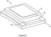
- Figure 3 shows schematically a perspective view of one of the seal segments 28.
- the segment 28 has a lightly curved, plate-like, rectangular shape.
- a radially outer, body portion 34 of the segment 28 is formed from continuous fibre reinforced ceramic matrix composite, as discussed in more detail below.
- a thermal barrier coating 35 is formed on the radially inward facing surface of the body portion 34.
- the gasket-type sealing ring 33 (not shown in Figure 3 ) runs around the edges of the radially outer surface of the body portion 34.
- Respective birdmouth slots 36 extend in the circumferential direction along the front and rear sides of the body portion 34.
- the plate is split into two or more arc sections allowing the segments to be loaded thereon by circumferential sliding. The arc sections are then joined together to form the backing plate.
- a sacrificial wax pattern is produced having a pattern surface that corresponds to the shape of the gas-washed surface of the seal segment.
- the pattern is dipped or otherwise coated in a ceramic slurry containing e.g. silicate, alumina, mullite and/or zirconia and allowed to dry. The dipping and drying process is continued until a desired thickness of slurry is built up.
- the slurry is preferably de-gassed prior to dipping.
- additional particulate media can be added to the layer, such as hollow or solid ceramic particles, ceramic whiskers, ceramic discontinuous fibres and/or ceramic platelets.
- Hollow members can also be embedded in the slurry and/or located at the surface of the slurry to act as cooling channels in the seal segment.
- sacrificial wax or polymer members can be embedded in the slurry and/or located at this surface, and can subsequently be burnt or melted out to form the cooling channels. The procedure is thus similar to that used in investment casting to produce a ceramic mould.
- Dewaxing is then performed by heating the coated pattern, which allows the wax to melt away and/or vaporise, to leave a self-supporting ceramic layer corresponding to the coating 35 that is fired to remove all liquid components and sinter the ceramic in the slurry.
- the firing can be postponed to be performed simultaneously with the firing that produces the ceramic matrix composite body portion 34 of the seal segment 28.
- the optional particulate media added to the ceramic layer can be used to: enhance the keying of the coating 35 to the body portion 34, tailor the coefficient of thermal expansion of the coating, control the abradability of the coating etc.
- a green ceramic matrix composite body is formed on a surface of the ceramic layer (typically the surface that has not been in contact with the wax pattern).
- a ceramic cement may be applied to the surface before the green body is formed thereon.
- the green body can be produced by stacking successive plys formed from a cloth of woven continuous fibre reinforcement. Each ply is covered in a water-based slurry containing a binder and ceramic. The slurry can be applied after each ply is stacked, or the slurry can be pre-impregnated into the plys before stacking.
- the reinforcement fibres can be bunched together to form a tow, and for each ply the tows woven in to a cloth (or sheet). The stacked plys are pressed to remove excess slurry, and heated which allows the binder to produce the green body.
- the green body with the ceramic layer is then fired in a furnace (or alternatively fired directly in an engine environment) to drive off residual moisture and sinter the ceramic particles to form the surrounding matrix of the ceramic matrix composite body portion 34 (and also to fire the ceramic layer if that has not already been done).
- the green body may be heated initially slowly to 100°C to drive off residual moisture then ramped up to over 1100°C to sinter the solids in the matrix.
- Tooling may be removed after the initial slow heating and before the sintering. Varying the pressure and temperature of the processing can give different levels of densification and therefore can vary the resultant mechanical properties of the component.
- the sintering may be performed in a vacuum or reduced pressure.
- the matrix is also bonded to the fibres and contains a distribution of micro-cracks which open and close as the component is loaded.
- the material is generally notch insensitive, unlike a monolithic ceramic.
- the temperature capability of such a composite may be conservatively 1150°C for continuous use, but can be taken over 1200°C for short excursions.
- the reinforcement fibres can be Nextel720TM and/or Nextel610TM alumina silicate fibres available from 3M or similar
- the ceramic particles can be alumina particles or a mixture of alumina and silicate particles.
- Ox/Ox ceramic matrix composite materials which are suitable for green body and sintering procedure discussed above.
- a SiC/SiC composite body can be manufactured by CVI (chemical vapour infiltration) and/or MI (melt infiltration) of SiC matrix material into a lay-up of SiC reinforcement fibres situated on a surface of the ceramic layer.
- the shape capability of this process is only limited by the capability to shape the pattern.
- other components that can potentially be made in the same fashion include: combustion tiles, flameholders, jet pipe liners, nozzle petals, nozzle guide vanes and turbine blades.
- wax is generally a convenient choice for the material of the pattern, other materials may be used.
- a reusable pattern may be used, e.g. formed of steel, aluminium, plastic or wood.
- a release agent may be used in conjunction with a reusable pattern.
- the pattern may remain attached to the ceramic layer during formation of the ceramic matrix composite body. In this case, however, the pattern should preferably have a coefficient of thermal expansion that is matched to that of the coating, particularly if elevated temperatures are used to dry the slurry.
- a further advantage of the process is that the ceramic layer is fired at a higher temperature than the ceramic matrix composite.
- the layer would be cast onto the ceramic matrix composite so that the coating is fired at a lower temperature, or the coating would be formed separately and then cemented to the ceramic matrix composite which can result in a weak interfacial bond.
Landscapes
- Engineering & Computer Science (AREA)
- Chemical & Material Sciences (AREA)
- Mechanical Engineering (AREA)
- Ceramic Engineering (AREA)
- Materials Engineering (AREA)
- General Engineering & Computer Science (AREA)
- Composite Materials (AREA)
- Turbine Rotor Nozzle Sealing (AREA)
Description
- The present invention relates to a method of forming a ceramic matrix composite component, such as a gas turbine engine component.
- The performance of gas turbine engines, whether measured in terms of efficiency or specific output, is improved by increasing the turbine gas temperature. It is therefore desirable to operate the turbines at the highest possible temperatures. For any engine cycle compression ratio or bypass ratio, increasing the turbine entry gas temperature produces more specific thrust (e.g. engine thrust per unit of air mass flow). However, as turbine entry temperatures increase, it is necessary to develop components and materials better able to withstand the increased temperatures.
- This has led, for example, to the replacement of metallic shroud segments with ceramic matrix composite shroud segments having higher temperature capabilities. To accommodate the change in material, however, adaptations to the segments have been proposed. For example,
EP 0751104 discloses a ceramic segment having an aluminium phosphate-based abradable seal coating which is suitable for use with nickel base turbine blades, andEP 1965030 discloses a hollow section ceramic seal segment. - Whereas metallic materials allow operational temperatures up to 1150°C, some ceramic matrix composites are able to operate up to 1350°C. However, current turbine temperatures are around 1300-1400°C and an aim is to increase these further. Accordingly, even ceramic matrix composites may need thermal protection. One option is to apply a thermal barrier coating to the composite based, for example, on the type of coating system described in
EP 0751104 . - Such coatings can be cast onto the ceramic matrix composite component. However, during drying and firing shrinkage may occur causing strain at the interfacial joint between materials, weakening the bond/mechanical strength/capability. Also the firing temperature of the coating must generally be lower than that of the composite to prevent a loss of properties in the composite, which limits the options for structuring the coating or can lead to undesirable further sintering of the coating in the engine. Such uncontrolled sintering may result in reactions with or inclusion of undesirable elements. Alternatively, the coating can be sintered and then adhered to the component using ceramic cement, but this can result in a relatively weak interfacial bond.
-
US4936939A andUS5682594A disclose methods for producing ceramic matrix composites. - It would be desirable to provide an alternative method for coating a ceramic matrix composite component.
- Accordingly, in a first aspect, the present invention provides a method of forming a ceramic matrix composite component, according to claim 1.
- Advantageously, forming the ceramic layer (which may serve as a thermal barrier or abradable coating) before the ceramic matrix composite body, allows the layer to be fired at a higher temperature than the forming temperature of the composite body and can help to prevent undesirable further sintering of the layer in use (e.g. in an engine).
- Optional features of the invention will now be set out. Unless indicated otherwise, these are applicable singly or in any combination with any aspect of the invention.
- The step of forming the ceramic matrix composite body may be performed by: forming a green ceramic matrix composite body on a surface of the ceramic layer; and sintering the green body to produce a ceramic matrix composite component with the ceramic layer attached thereto. During the sintering, pressure may be applied to force the ceramic layer and the green body together. The sintering may be performed in a vacuum or reduced pressure. The forming of the green body may include the sub-steps of: stacking successive plys of continuous fibre reinforcement on the surface of the ceramic layer, each stacked ply being covered in a slurry containing binder and ceramic; and processing (e.g. pressing and/or heating) the stacked and slurry-covered plys such that the stacked plys are embedded in a green ceramic matrix. The sintering of the green body then fuses the green ceramic matrix.
- However, other techniques for forming the ceramic matrix composite body include, for example, chemical vapour infiltration or melt infiltration of a ceramic matrix material into a lay-up of ceramic reinforcement fibres situated on the surface of the ceramic layer.
- The method may include a further step of removing the pattern element from the ceramic layer. For example, the removing step may be performed between the drying step and the forming step. However, the removing step may be performed as a final step, after the ceramic matrix composite component is produced with the ceramic layer attached thereto. The method may include a step of sintering the ceramic layer, e.g. before the forming step. If the pattern element is removed between the drying step and the forming step, then the separate sintering step may be performed after the removal.
- The ceramic matrix composite component with the attached ceramic layer may be subsequently processed, e.g. by machining. For example, attachment formations and/or an improved surface finish can be provided.
- The surface of the ceramic layer may be processed, e.g. by machining, before the ceramic matrix composite body is formed thereon. For example, it may be roughened or otherwise configured by mechanical keying and/or increased surface area to improve the bond strength to the body. Additionally or alternatively such surface features may be moulded in as part of the coating step.
- The pattern element may be sacrificial. For example it may be a wax element. Wax pattern elements are conventionally used in investment casting procedures, for example for the production of turbine blades. They are highly flexible in terms of the final shapes that can be produced based on such pattern elements. Removal or "dewaxing" of the pattern element is also then straightforward to perform.
- The slurry may be de-gassed before the coating step. This can reduce the amount of incumbent or entrapped air which can reduce bond strengths and structural properties.
- The coating step can include building up successive layers of ceramic slurry on the pattern element. For example, the ceramic slurry may include silicate, alumina, mullite and/or zirconia. Each layer of the slurry may be modified to suit its requirements, e.g. by changing the shape, size or phase of the slurry particles or by incorporating particulates as discussed below.
- The coating step can include incorporating particulates in the slurry, and thereby in the ceramic layer. For example, the particulates may be ceramic hollow particles, ceramic solid particles, ceramic whiskers, ceramic discontinuous fibres and/or ceramic platelets. The particulates can be pre-mixed in the slurry and applied to the pattern element therewith. Another option is for, the coating step to include building up successive and alternate layers of slurry and particulate.
- The particulates can be incorporated at specific locations, for example at the surface of the ceramic layer on which the green ceramic matrix composite body is formed. By incorporating particulates at this surface, features can be introduced to key the layer to the composite body. Particles, e.g. providing enhanced abradability, may be provided at the opposite surface of the ceramic layer (i.e. adjacent the pattern element).
- The coating step can include embedding hollow or sacrificial members in the ceramic slurry and/or locating hollow or sacrificial members at the surface of the ceramic slurry, the hollow or sacrificial members forming cooling channels in the ceramic layer and/or at the surface on which the ceramic matrix composite body is formed. For example, sacrificial members can be formed of wax or polymer and can be burnt or melted out during sintering to form the cooling channels. The channels may typically have a diameter in the range from 0.05 to 1 mm. In use, cooling air can flow through the channels to cool the component.
- The method may include the further step of applying a ceramic cement to the surface of the ceramic layer before the step of forming the ceramic matrix composite body on the surface. The component may be a gas turbine engine component. For example, the component may be a combustion tile, a seal segment for a shroud ring of a rotor, a flame holder, a jet pipe liner, a nozzle petal, a nozzle guide vane or a turbine blade. If the forming step is performed by forming a green ceramic matrix composite body and then sintering the green body, the sintering of the green body can be performed in situ in the engine.
- Further optional features of the invention are set out below.
- Embodiments of the invention will now be described by way of example with reference to the accompanying drawings in which:
-
Figure 1 shows a longitudinal sectional elevation through a ducted fan gas turbine engine; -
Figure 2 shows schematically a sectional elevation through a portion of the high pressure turbine of the engine ofFigure 1 ; and -
Figure 3 shows schematically a perspective view of a seal segment. - With reference to
Figure 1 , a ducted fan gas turbine engine generally indicated at 10 has a principal and rotational axis X-X. The engine comprises, in axial flow series, anair intake 11, apropulsive fan 12, anintermediate pressure compressor 13, a high-pressure compressor 14,combustion equipment 15, a high-pressure turbine 16, andintermediate pressure turbine 17, a low-pressure turbine 18 and a coreengine exhaust nozzle 19. Anacelle 21 generally surrounds theengine 10 and defines theintake 11, abypass duct 22 and abypass exhaust nozzle 23. - The
gas turbine engine 10 works in a conventional manner so that air entering theintake 11 is accelerated by thefan 12 to produce two air flows: a first air flow A into theintermediate pressure compressor 13 and a second air flow B which passes through thebypass duct 22 to provide propulsive thrust. Theintermediate pressure compressor 13 compresses the air flow A directed into it before delivering that air to thehigh pressure compressor 14 where further compression takes place. - The compressed air exhausted from the high-
pressure compressor 14 is directed into thecombustion equipment 15 where it is mixed with fuel and the mixture combusted. The resultant hot combustion products then expand through, and thereby drive the high, intermediate and low-pressure turbines nozzle 19 to provide additional propulsive thrust. The high, intermediate and low-pressure turbines respectively drive the high andintermediate pressure compressors fan 12 by suitable interconnecting shafts. - The
high pressure turbine 16 includes an annular array of radially extendingrotor aerofoil blades 24, the radially outer part of one of which can be seen if reference is now made toFigure 2 , which shows schematically a sectional elevation through a portion of the high pressure turbine. Hot turbine gases flow overnozzle guide vanes 25 and theaerofoil blades 24 in the direction generally indicated by the arrow. Ashroud ring 27 in accordance with the present invention is positioned radially outwardly of theshroudless aerofoil blades 24. Theshroud ring 27 serves to define the radially outer extent of a short length of thegas passage 26 through thehigh pressure turbine 16. - The turbine gases flowing over the radially inward facing surface of the
shroud ring 27 are at extremely high temperatures. Consequently, at least that portion of thering 27 must be constructed from a material which is capable of withstanding those temperatures whilst maintaining its structural integrity. Ceramic materials are particularly well suited to this sort of application. - The
shroud ring 27 is formed from an annular array ofseal segments 28 attached to a part of the engine casing which takes the form of an annular,metallic backing plate 29 having a central portion and radially inwardly projecting, front and rear flanges, with inwardly directed hooks 30 formed at the ends of the flanges. Cooling air for thering 27 enters aspace 31 formed between thebacking plate 29, eachsegment 28 and a gasket-type sealing ring 33 located between theplate 29 and thesegment 28, the air being continuously replenished as it leaks, under a pressure gradient, into the working gas annulus through suitable holes (not shown) in thebacking plate 29. Thebacking plate 29 is sealed at its front and rear sides to adjacent parts of the engine casing by piston ring-type sealing formations 32 of conventional design. -
Figure 3 shows schematically a perspective view of one of theseal segments 28. Thesegment 28 has a lightly curved, plate-like, rectangular shape. A radially outer,body portion 34 of thesegment 28 is formed from continuous fibre reinforced ceramic matrix composite, as discussed in more detail below. Athermal barrier coating 35 is formed on the radially inward facing surface of thebody portion 34. The gasket-type sealing ring 33 (not shown inFigure 3 ) runs around the edges of the radially outer surface of thebody portion 34. -
Respective birdmouth slots 36 extend in the circumferential direction along the front and rear sides of thebody portion 34. To mount theseal segment 28 to thebacking plate 29, the plate is split into two or more arc sections allowing the segments to be loaded thereon by circumferential sliding. The arc sections are then joined together to form the backing plate. - To produce the
seal segment 28, a sacrificial wax pattern is produced having a pattern surface that corresponds to the shape of the gas-washed surface of the seal segment. The pattern is dipped or otherwise coated in a ceramic slurry containing e.g. silicate, alumina, mullite and/or zirconia and allowed to dry. The dipping and drying process is continued until a desired thickness of slurry is built up. The slurry is preferably de-gassed prior to dipping. During the build-up, additional particulate media can be added to the layer, such as hollow or solid ceramic particles, ceramic whiskers, ceramic discontinuous fibres and/or ceramic platelets. Hollow members can also be embedded in the slurry and/or located at the surface of the slurry to act as cooling channels in the seal segment. Similarly, sacrificial wax or polymer members can be embedded in the slurry and/or located at this surface, and can subsequently be burnt or melted out to form the cooling channels. The procedure is thus similar to that used in investment casting to produce a ceramic mould. - Dewaxing is then performed by heating the coated pattern, which allows the wax to melt away and/or vaporise, to leave a self-supporting ceramic layer corresponding to the
coating 35 that is fired to remove all liquid components and sinter the ceramic in the slurry. Alternatively, the firing can be postponed to be performed simultaneously with the firing that produces the ceramic matrixcomposite body portion 34 of theseal segment 28. - The optional particulate media added to the ceramic layer can be used to: enhance the keying of the
coating 35 to thebody portion 34, tailor the coefficient of thermal expansion of the coating, control the abradability of the coating etc. - A green ceramic matrix composite body is formed on a surface of the ceramic layer (typically the surface that has not been in contact with the wax pattern). To enhance bonding, a ceramic cement may be applied to the surface before the green body is formed thereon. More particularly, the green body can be produced by stacking successive plys formed from a cloth of woven continuous fibre reinforcement. Each ply is covered in a water-based slurry containing a binder and ceramic. The slurry can be applied after each ply is stacked, or the slurry can be pre-impregnated into the plys before stacking. The reinforcement fibres can be bunched together to form a tow, and for each ply the tows woven in to a cloth (or sheet). The stacked plys are pressed to remove excess slurry, and heated which allows the binder to produce the green body.
- The green body with the ceramic layer is then fired in a furnace (or alternatively fired directly in an engine environment) to drive off residual moisture and sinter the ceramic particles to form the surrounding matrix of the ceramic matrix composite body portion 34 (and also to fire the ceramic layer if that has not already been done). For example, the green body may be heated initially slowly to 100°C to drive off residual moisture then ramped up to over 1100°C to sinter the solids in the matrix. Tooling may be removed after the initial slow heating and before the sintering. Varying the pressure and temperature of the processing can give different levels of densification and therefore can vary the resultant mechanical properties of the component. The sintering may be performed in a vacuum or reduced pressure. The matrix is also bonded to the fibres and contains a distribution of micro-cracks which open and close as the component is loaded. The material is generally notch insensitive, unlike a monolithic ceramic. The temperature capability of such a composite may be conservatively 1150°C for continuous use, but can be taken over 1200°C for short excursions.
- Features such as the
birdmouth slots 36 can be produced by subsequent machining. - By way of example, the reinforcement fibres can be Nextel720™ and/or Nextel610™ alumina silicate fibres available from 3M or similar, the ceramic particles can be alumina particles or a mixture of alumina and silicate particles. These are examples of Ox/Ox ceramic matrix composite materials, which are suitable for green body and sintering procedure discussed above. Another option, however, is to form the ceramic matrix composite body from a SiC/SiC ceramic matrix composite material, having a silicon carbide based matrix and silicon carbide based reinforcement fibres. A SiC/SiC composite body can be manufactured by CVI (chemical vapour infiltration) and/or MI (melt infiltration) of SiC matrix material into a lay-up of SiC reinforcement fibres situated on a surface of the ceramic layer.
- Advantageously, the shape capability of this process is only limited by the capability to shape the pattern. Thus, although described above in relation to a seal segment, other components that can potentially be made in the same fashion include: combustion tiles, flameholders, jet pipe liners, nozzle petals, nozzle guide vanes and turbine blades. Further, although wax is generally a convenient choice for the material of the pattern, other materials may be used. For example, rather than having a sacrificial pattern that burns or melts off, a reusable pattern may be used, e.g. formed of steel, aluminium, plastic or wood. A release agent may be used in conjunction with a reusable pattern. Additionally or alternatively, the pattern may remain attached to the ceramic layer during formation of the ceramic matrix composite body. In this case, however, the pattern should preferably have a coefficient of thermal expansion that is matched to that of the coating, particularly if elevated temperatures are used to dry the slurry.
- A further advantage of the process is that the ceramic layer is fired at a higher temperature than the ceramic matrix composite. Conventionally, as described in
EP 0751104 , the layer would be cast onto the ceramic matrix composite so that the coating is fired at a lower temperature, or the coating would be formed separately and then cemented to the ceramic matrix composite which can result in a weak interfacial bond.
Claims (11)
- A method of forming a ceramic matrix composite component, the method including the steps of:providing a pattern element for the ceramic coating;coating the pattern element with a ceramic coating slurry;drying the slurry to form a ceramic coating layer;sintering the ceramic coating layer at a first temperature;forming a ceramic matrix composite body on a surface of the sintered ceramic coating layer and sintering the ceramic matrix composite body on the surface of the sintered ceramic coating layer at a second temperature to produce a ceramic matrix composite component with the ceramic coating layer attached thereto wherein the second temperature is lower than the first temperature.
- A method according to claim 1, wherein the step of forming the ceramic matrix composite body is performed by: forming a green ceramic matrix composite body on a surface of the ceramic coating layer; and sintering the green body to produce a ceramic matrix composite component with the ceramic coating layer attached thereto.
- A method according to claim 2, wherein the forming of the green ceramic matrix composite body includes the sub-steps of:stacking successive plys of continuous fibre reinforcement on the surface of the ceramic coating layer, each stacked ply being covered in a slurry containing binder and ceramic; andprocessing the stacked and slurry-covered plys such that the stacked plys are embedded in a green ceramic matrix.
- A method according to any one of the previous claims, including a further step of removing the pattern element from the ceramic coating layer.
- A method according to any one of the previous claims, wherein the pattern element is a sacrificial pattern element.
- A method according to any one of the previous claims, wherein the coating step includes building up successive layers of ceramic coating slurry on the pattern element.
- A method according to any one of the previous claims, wherein the coating step includes incorporating particulates in the slurry, and thereby in the ceramic coating layer and wherein the particulates serve to enhance the keying of the ceramic layer to the ceramic matrix composite body in the ceramic matrix composite component.
- A method according to any one of the previous claims, wherein the coating step includes embedding hollow or sacrificial members in the ceramic coating slurry and/or locating hollow or sacrificial members at the surface of the ceramic coating slurry, the hollow members or sacrificial forming cooling channels in the ceramic coating layer and/or at the surface on which the ceramic matrix composite body is formed.
- A method according to any one of the previous claims, including a further step of applying a ceramic cement to the surface of the ceramic coating layer before the step of forming the ceramic matrix composite body thereon.
- A method according to any one of the previous claims, wherein the component is a gas turbine engine component.
- A method according to claim 1 0 as dependent on claim 2, wherein the sintering of the green body is performed in situ in the engine.
Applications Claiming Priority (1)
| Application Number | Priority Date | Filing Date | Title |
|---|---|---|---|
| GBGB1303994.6A GB201303994D0 (en) | 2013-03-06 | 2013-03-06 | Ceramic matrix composite component forming method |
Publications (2)
| Publication Number | Publication Date |
|---|---|
| EP2774754A1 EP2774754A1 (en) | 2014-09-10 |
| EP2774754B1 true EP2774754B1 (en) | 2021-05-12 |
Family
ID=48142499
Family Applications (1)
| Application Number | Title | Priority Date | Filing Date |
|---|---|---|---|
| EP14157415.2A Active EP2774754B1 (en) | 2013-03-06 | 2014-03-03 | Ceramic matrix composite component forming method |
Country Status (3)
| Country | Link |
|---|---|
| US (1) | US20140255665A1 (en) |
| EP (1) | EP2774754B1 (en) |
| GB (1) | GB201303994D0 (en) |
Families Citing this family (6)
| Publication number | Priority date | Publication date | Assignee | Title |
|---|---|---|---|---|
| US10895545B2 (en) * | 2013-10-14 | 2021-01-19 | Raytheon Technologies Corporation | Method of detecting conversion quality of green matrix composite material and system for same |
| EP3034263A1 (en) | 2014-12-19 | 2016-06-22 | Sadair Spear AB | Method for manufacturing a fibre-reinforced structure, mandrel, molding system and fibre-reinforced structure |
| US10093586B2 (en) * | 2015-02-26 | 2018-10-09 | General Electric Company | Ceramic matrix composite articles and methods for forming same |
| US10821681B2 (en) | 2017-01-20 | 2020-11-03 | General Electric Company | Liquid infusion molded ceramic matrix composites and methods of forming the same |
| US10384981B2 (en) | 2017-06-14 | 2019-08-20 | General Electric Company | Methods of forming ceramic matrix composites using sacrificial fibers and related products |
| US11180421B2 (en) | 2019-09-04 | 2021-11-23 | Rolls-Royce Corporation | Repair and/or reinforcement of oxide-oxide CMC |
Family Cites Families (5)
| Publication number | Priority date | Publication date | Assignee | Title |
|---|---|---|---|---|
| US5682594A (en) * | 1987-06-12 | 1997-10-28 | Lanxide Technology Company, Lp | Composite materials and methods for making the same |
| US4936939A (en) * | 1989-05-05 | 1990-06-26 | Ceracom Technologies, Inc. | Fabric-reinforced ceramic matrix composite material |
| US6197843B1 (en) * | 1996-04-30 | 2001-03-06 | The Dow Chemical Company | Method for preparing ceramic articles |
| US7563504B2 (en) * | 1998-03-27 | 2009-07-21 | Siemens Energy, Inc. | Utilization of discontinuous fibers for improving properties of high temperature insulation of ceramic matrix composites |
| US6733907B2 (en) * | 1998-03-27 | 2004-05-11 | Siemens Westinghouse Power Corporation | Hybrid ceramic material composed of insulating and structural ceramic layers |
-
2013
- 2013-03-06 GB GBGB1303994.6A patent/GB201303994D0/en not_active Ceased
-
2014
- 2014-03-03 EP EP14157415.2A patent/EP2774754B1/en active Active
- 2014-03-04 US US14/196,489 patent/US20140255665A1/en not_active Abandoned
Non-Patent Citations (1)
| Title |
|---|
| None * |
Also Published As
| Publication number | Publication date |
|---|---|
| GB201303994D0 (en) | 2013-04-17 |
| EP2774754A1 (en) | 2014-09-10 |
| US20140255665A1 (en) | 2014-09-11 |
Similar Documents
| Publication | Publication Date | Title |
|---|---|---|
| CN109534835B (en) | Ceramic matrix composite articles and methods of forming the same | |
| US11149569B2 (en) | Flow path assembly with airfoils inserted through flow path boundary | |
| US10569481B2 (en) | Shaped composite ply layups and methods for shaping composite ply layups | |
| EP2774754B1 (en) | Ceramic matrix composite component forming method | |
| JP6979761B2 (en) | Ceramic Matrix Composite Components and Ceramic Matrix Composites | |
| JP6888933B2 (en) | Ceramic Matrix Composite Components and Methods for Manufacturing Ceramic Matrix Composite Components | |
| US11441436B2 (en) | Flow path assemblies for gas turbine engines and assembly methods therefore | |
| JP7187094B2 (en) | CMC components having microchannels and methods for forming microchannels in CMC components | |
| JP6855100B2 (en) | Single flow path structure | |
| CA2747364C (en) | Ceramic matrix composite blade having integral platform structures and methods of fabrication | |
| JP6861833B2 (en) | Single flow path structure | |
| EP2728125A1 (en) | Method of forming a ceramic matrix composite component and corresponding ceramic matrix composite gas turbine engine component | |
| JP2017105698A5 (en) | ||
| US11149575B2 (en) | Airfoil fluid curtain to mitigate or prevent flow path leakage | |
| EP3475082A1 (en) | Ceramic matrix composite component for a gas turbine engine | |
| EP3459733B1 (en) | Method for forming ceramic matrix composite articles | |
| EP3378846B1 (en) | Method for forming passages in composite components | |
| WO2020023021A1 (en) | Ceramic matrix composite materials having reduced anisotropic sintering shrinkage |
Legal Events
| Date | Code | Title | Description |
|---|---|---|---|
| PUAI | Public reference made under article 153(3) epc to a published international application that has entered the european phase |
Free format text: ORIGINAL CODE: 0009012 |
|
| 17P | Request for examination filed |
Effective date: 20140303 |
|
| AK | Designated contracting states |
Kind code of ref document: A1 Designated state(s): AL AT BE BG CH CY CZ DE DK EE ES FI FR GB GR HR HU IE IS IT LI LT LU LV MC MK MT NL NO PL PT RO RS SE SI SK SM TR |
|
| AX | Request for extension of the european patent |
Extension state: BA ME |
|
| R17P | Request for examination filed (corrected) |
Effective date: 20150225 |
|
| RBV | Designated contracting states (corrected) |
Designated state(s): AL AT BE BG CH CY CZ DE DK EE ES FI FR GB GR HR HU IE IS IT LI LT LU LV MC MK MT NL NO PL PT RO RS SE SI SK SM TR |
|
| RAP1 | Party data changed (applicant data changed or rights of an application transferred) |
Owner name: ROLLS-ROYCE PLC |
|
| STAA | Information on the status of an ep patent application or granted ep patent |
Free format text: STATUS: EXAMINATION IS IN PROGRESS |
|
| 17Q | First examination report despatched |
Effective date: 20171018 |
|
| RAP1 | Party data changed (applicant data changed or rights of an application transferred) |
Owner name: ROLLS-ROYCE PLC |
|
| STAA | Information on the status of an ep patent application or granted ep patent |
Free format text: STATUS: EXAMINATION IS IN PROGRESS |
|
| GRAP | Despatch of communication of intention to grant a patent |
Free format text: ORIGINAL CODE: EPIDOSNIGR1 |
|
| STAA | Information on the status of an ep patent application or granted ep patent |
Free format text: STATUS: GRANT OF PATENT IS INTENDED |
|
| GRAS | Grant fee paid |
Free format text: ORIGINAL CODE: EPIDOSNIGR3 |
|
| GRAA | (expected) grant |
Free format text: ORIGINAL CODE: 0009210 |
|
| STAA | Information on the status of an ep patent application or granted ep patent |
Free format text: STATUS: THE PATENT HAS BEEN GRANTED |
|
| INTG | Intention to grant announced |
Effective date: 20210316 |
|
| AK | Designated contracting states |
Kind code of ref document: B1 Designated state(s): AL AT BE BG CH CY CZ DE DK EE ES FI FR GB GR HR HU IE IS IT LI LT LU LV MC MK MT NL NO PL PT RO RS SE SI SK SM TR |
|
| REG | Reference to a national code |
Ref country code: GB Ref legal event code: FG4D |
|
| REG | Reference to a national code |
Ref country code: CH Ref legal event code: EP |
|
| REG | Reference to a national code |
Ref country code: DE Ref legal event code: R096 Ref document number: 602014077365 Country of ref document: DE |
|
| REG | Reference to a national code |
Ref country code: IE Ref legal event code: FG4D |
|
| REG | Reference to a national code |
Ref country code: AT Ref legal event code: REF Ref document number: 1391916 Country of ref document: AT Kind code of ref document: T Effective date: 20210615 |
|
| REG | Reference to a national code |
Ref country code: LT Ref legal event code: MG9D |
|
| REG | Reference to a national code |
Ref country code: AT Ref legal event code: MK05 Ref document number: 1391916 Country of ref document: AT Kind code of ref document: T Effective date: 20210512 |
|
| REG | Reference to a national code |
Ref country code: NL Ref legal event code: MP Effective date: 20210512 |
|
| PG25 | Lapsed in a contracting state [announced via postgrant information from national office to epo] |
Ref country code: HR Free format text: LAPSE BECAUSE OF FAILURE TO SUBMIT A TRANSLATION OF THE DESCRIPTION OR TO PAY THE FEE WITHIN THE PRESCRIBED TIME-LIMIT Effective date: 20210512 Ref country code: AT Free format text: LAPSE BECAUSE OF FAILURE TO SUBMIT A TRANSLATION OF THE DESCRIPTION OR TO PAY THE FEE WITHIN THE PRESCRIBED TIME-LIMIT Effective date: 20210512 Ref country code: BG Free format text: LAPSE BECAUSE OF FAILURE TO SUBMIT A TRANSLATION OF THE DESCRIPTION OR TO PAY THE FEE WITHIN THE PRESCRIBED TIME-LIMIT Effective date: 20210812 Ref country code: LT Free format text: LAPSE BECAUSE OF FAILURE TO SUBMIT A TRANSLATION OF THE DESCRIPTION OR TO PAY THE FEE WITHIN THE PRESCRIBED TIME-LIMIT Effective date: 20210512 Ref country code: FI Free format text: LAPSE BECAUSE OF FAILURE TO SUBMIT A TRANSLATION OF THE DESCRIPTION OR TO PAY THE FEE WITHIN THE PRESCRIBED TIME-LIMIT Effective date: 20210512 |
|
| PG25 | Lapsed in a contracting state [announced via postgrant information from national office to epo] |
Ref country code: LV Free format text: LAPSE BECAUSE OF FAILURE TO SUBMIT A TRANSLATION OF THE DESCRIPTION OR TO PAY THE FEE WITHIN THE PRESCRIBED TIME-LIMIT Effective date: 20210512 Ref country code: GR Free format text: LAPSE BECAUSE OF FAILURE TO SUBMIT A TRANSLATION OF THE DESCRIPTION OR TO PAY THE FEE WITHIN THE PRESCRIBED TIME-LIMIT Effective date: 20210813 Ref country code: IS Free format text: LAPSE BECAUSE OF FAILURE TO SUBMIT A TRANSLATION OF THE DESCRIPTION OR TO PAY THE FEE WITHIN THE PRESCRIBED TIME-LIMIT Effective date: 20210912 Ref country code: SE Free format text: LAPSE BECAUSE OF FAILURE TO SUBMIT A TRANSLATION OF THE DESCRIPTION OR TO PAY THE FEE WITHIN THE PRESCRIBED TIME-LIMIT Effective date: 20210512 Ref country code: RS Free format text: LAPSE BECAUSE OF FAILURE TO SUBMIT A TRANSLATION OF THE DESCRIPTION OR TO PAY THE FEE WITHIN THE PRESCRIBED TIME-LIMIT Effective date: 20210512 Ref country code: PT Free format text: LAPSE BECAUSE OF FAILURE TO SUBMIT A TRANSLATION OF THE DESCRIPTION OR TO PAY THE FEE WITHIN THE PRESCRIBED TIME-LIMIT Effective date: 20210913 Ref country code: NO Free format text: LAPSE BECAUSE OF FAILURE TO SUBMIT A TRANSLATION OF THE DESCRIPTION OR TO PAY THE FEE WITHIN THE PRESCRIBED TIME-LIMIT Effective date: 20210812 Ref country code: PL Free format text: LAPSE BECAUSE OF FAILURE TO SUBMIT A TRANSLATION OF THE DESCRIPTION OR TO PAY THE FEE WITHIN THE PRESCRIBED TIME-LIMIT Effective date: 20210512 Ref country code: ES Free format text: LAPSE BECAUSE OF FAILURE TO SUBMIT A TRANSLATION OF THE DESCRIPTION OR TO PAY THE FEE WITHIN THE PRESCRIBED TIME-LIMIT Effective date: 20210512 |
|
| PG25 | Lapsed in a contracting state [announced via postgrant information from national office to epo] |
Ref country code: NL Free format text: LAPSE BECAUSE OF FAILURE TO SUBMIT A TRANSLATION OF THE DESCRIPTION OR TO PAY THE FEE WITHIN THE PRESCRIBED TIME-LIMIT Effective date: 20210512 |
|
| PG25 | Lapsed in a contracting state [announced via postgrant information from national office to epo] |
Ref country code: CZ Free format text: LAPSE BECAUSE OF FAILURE TO SUBMIT A TRANSLATION OF THE DESCRIPTION OR TO PAY THE FEE WITHIN THE PRESCRIBED TIME-LIMIT Effective date: 20210512 Ref country code: DK Free format text: LAPSE BECAUSE OF FAILURE TO SUBMIT A TRANSLATION OF THE DESCRIPTION OR TO PAY THE FEE WITHIN THE PRESCRIBED TIME-LIMIT Effective date: 20210512 Ref country code: EE Free format text: LAPSE BECAUSE OF FAILURE TO SUBMIT A TRANSLATION OF THE DESCRIPTION OR TO PAY THE FEE WITHIN THE PRESCRIBED TIME-LIMIT Effective date: 20210512 Ref country code: SK Free format text: LAPSE BECAUSE OF FAILURE TO SUBMIT A TRANSLATION OF THE DESCRIPTION OR TO PAY THE FEE WITHIN THE PRESCRIBED TIME-LIMIT Effective date: 20210512 Ref country code: SM Free format text: LAPSE BECAUSE OF FAILURE TO SUBMIT A TRANSLATION OF THE DESCRIPTION OR TO PAY THE FEE WITHIN THE PRESCRIBED TIME-LIMIT Effective date: 20210512 Ref country code: RO Free format text: LAPSE BECAUSE OF FAILURE TO SUBMIT A TRANSLATION OF THE DESCRIPTION OR TO PAY THE FEE WITHIN THE PRESCRIBED TIME-LIMIT Effective date: 20210512 |
|
| REG | Reference to a national code |
Ref country code: DE Ref legal event code: R097 Ref document number: 602014077365 Country of ref document: DE |
|
| PLBE | No opposition filed within time limit |
Free format text: ORIGINAL CODE: 0009261 |
|
| STAA | Information on the status of an ep patent application or granted ep patent |
Free format text: STATUS: NO OPPOSITION FILED WITHIN TIME LIMIT |
|
| 26N | No opposition filed |
Effective date: 20220215 |
|
| PG25 | Lapsed in a contracting state [announced via postgrant information from national office to epo] |
Ref country code: IS Free format text: LAPSE BECAUSE OF FAILURE TO SUBMIT A TRANSLATION OF THE DESCRIPTION OR TO PAY THE FEE WITHIN THE PRESCRIBED TIME-LIMIT Effective date: 20210912 Ref country code: AL Free format text: LAPSE BECAUSE OF FAILURE TO SUBMIT A TRANSLATION OF THE DESCRIPTION OR TO PAY THE FEE WITHIN THE PRESCRIBED TIME-LIMIT Effective date: 20210512 |
|
| PG25 | Lapsed in a contracting state [announced via postgrant information from national office to epo] |
Ref country code: IT Free format text: LAPSE BECAUSE OF FAILURE TO SUBMIT A TRANSLATION OF THE DESCRIPTION OR TO PAY THE FEE WITHIN THE PRESCRIBED TIME-LIMIT Effective date: 20210512 |
|
| PG25 | Lapsed in a contracting state [announced via postgrant information from national office to epo] |
Ref country code: MC Free format text: LAPSE BECAUSE OF FAILURE TO SUBMIT A TRANSLATION OF THE DESCRIPTION OR TO PAY THE FEE WITHIN THE PRESCRIBED TIME-LIMIT Effective date: 20210512 |
|
| REG | Reference to a national code |
Ref country code: CH Ref legal event code: PL |
|
| REG | Reference to a national code |
Ref country code: BE Ref legal event code: MM Effective date: 20220331 |
|
| PG25 | Lapsed in a contracting state [announced via postgrant information from national office to epo] |
Ref country code: LU Free format text: LAPSE BECAUSE OF NON-PAYMENT OF DUE FEES Effective date: 20220303 Ref country code: LI Free format text: LAPSE BECAUSE OF NON-PAYMENT OF DUE FEES Effective date: 20220331 Ref country code: IE Free format text: LAPSE BECAUSE OF NON-PAYMENT OF DUE FEES Effective date: 20220303 Ref country code: CH Free format text: LAPSE BECAUSE OF NON-PAYMENT OF DUE FEES Effective date: 20220331 |
|
| PG25 | Lapsed in a contracting state [announced via postgrant information from national office to epo] |
Ref country code: BE Free format text: LAPSE BECAUSE OF NON-PAYMENT OF DUE FEES Effective date: 20220331 |
|
| P01 | Opt-out of the competence of the unified patent court (upc) registered |
Effective date: 20230528 |
|
| PG25 | Lapsed in a contracting state [announced via postgrant information from national office to epo] |
Ref country code: HU Free format text: LAPSE BECAUSE OF FAILURE TO SUBMIT A TRANSLATION OF THE DESCRIPTION OR TO PAY THE FEE WITHIN THE PRESCRIBED TIME-LIMIT; INVALID AB INITIO Effective date: 20140303 |
|
| PG25 | Lapsed in a contracting state [announced via postgrant information from national office to epo] |
Ref country code: MK Free format text: LAPSE BECAUSE OF FAILURE TO SUBMIT A TRANSLATION OF THE DESCRIPTION OR TO PAY THE FEE WITHIN THE PRESCRIBED TIME-LIMIT Effective date: 20210512 Ref country code: CY Free format text: LAPSE BECAUSE OF FAILURE TO SUBMIT A TRANSLATION OF THE DESCRIPTION OR TO PAY THE FEE WITHIN THE PRESCRIBED TIME-LIMIT Effective date: 20210512 |
|
| PGFP | Annual fee paid to national office [announced via postgrant information from national office to epo] |
Ref country code: DE Payment date: 20240328 Year of fee payment: 11 Ref country code: GB Payment date: 20240319 Year of fee payment: 11 |
|
| PGFP | Annual fee paid to national office [announced via postgrant information from national office to epo] |
Ref country code: FR Payment date: 20240327 Year of fee payment: 11 |
|
| PG25 | Lapsed in a contracting state [announced via postgrant information from national office to epo] |
Ref country code: TR Free format text: LAPSE BECAUSE OF FAILURE TO SUBMIT A TRANSLATION OF THE DESCRIPTION OR TO PAY THE FEE WITHIN THE PRESCRIBED TIME-LIMIT Effective date: 20210512 |