EP1997691A2 - Interior panel assembly and airbag device - Google Patents
Interior panel assembly and airbag device Download PDFInfo
- Publication number
- EP1997691A2 EP1997691A2 EP08150606A EP08150606A EP1997691A2 EP 1997691 A2 EP1997691 A2 EP 1997691A2 EP 08150606 A EP08150606 A EP 08150606A EP 08150606 A EP08150606 A EP 08150606A EP 1997691 A2 EP1997691 A2 EP 1997691A2
- Authority
- EP
- European Patent Office
- Prior art keywords
- door
- interior panel
- leg
- backing plate
- airbag
- Prior art date
- Legal status (The legal status is an assumption and is not a legal conclusion. Google has not performed a legal analysis and makes no representation as to the accuracy of the status listed.)
- Granted
Links
- 238000003466 welding Methods 0.000 claims description 9
- 230000002093 peripheral effect Effects 0.000 abstract description 9
- 238000000926 separation method Methods 0.000 abstract description 5
- 238000003825 pressing Methods 0.000 description 4
- 238000000034 method Methods 0.000 description 1
- 238000010008 shearing Methods 0.000 description 1
Images





Classifications
-
- B—PERFORMING OPERATIONS; TRANSPORTING
- B60—VEHICLES IN GENERAL
- B60R—VEHICLES, VEHICLE FITTINGS, OR VEHICLE PARTS, NOT OTHERWISE PROVIDED FOR
- B60R21/00—Arrangements or fittings on vehicles for protecting or preventing injuries to occupants or pedestrians in case of accidents or other traffic risks
- B60R21/02—Occupant safety arrangements or fittings, e.g. crash pads
- B60R21/16—Inflatable occupant restraints or confinements designed to inflate upon impact or impending impact, e.g. air bags
- B60R21/20—Arrangements for storing inflatable members in their non-use or deflated condition; Arrangement or mounting of air bag modules or components
- B60R21/215—Arrangements for storing inflatable members in their non-use or deflated condition; Arrangement or mounting of air bag modules or components characterised by the covers for the inflatable member
-
- B—PERFORMING OPERATIONS; TRANSPORTING
- B60—VEHICLES IN GENERAL
- B60R—VEHICLES, VEHICLE FITTINGS, OR VEHICLE PARTS, NOT OTHERWISE PROVIDED FOR
- B60R21/00—Arrangements or fittings on vehicles for protecting or preventing injuries to occupants or pedestrians in case of accidents or other traffic risks
- B60R21/02—Occupant safety arrangements or fittings, e.g. crash pads
- B60R21/16—Inflatable occupant restraints or confinements designed to inflate upon impact or impending impact, e.g. air bags
- B60R21/20—Arrangements for storing inflatable members in their non-use or deflated condition; Arrangement or mounting of air bag modules or components
- B60R21/215—Arrangements for storing inflatable members in their non-use or deflated condition; Arrangement or mounting of air bag modules or components characterised by the covers for the inflatable member
- B60R2021/21537—Arrangements for storing inflatable members in their non-use or deflated condition; Arrangement or mounting of air bag modules or components characterised by the covers for the inflatable member characterised by hinges
-
- B—PERFORMING OPERATIONS; TRANSPORTING
- B60—VEHICLES IN GENERAL
- B60R—VEHICLES, VEHICLE FITTINGS, OR VEHICLE PARTS, NOT OTHERWISE PROVIDED FOR
- B60R21/00—Arrangements or fittings on vehicles for protecting or preventing injuries to occupants or pedestrians in case of accidents or other traffic risks
- B60R21/02—Occupant safety arrangements or fittings, e.g. crash pads
- B60R21/16—Inflatable occupant restraints or confinements designed to inflate upon impact or impending impact, e.g. air bags
- B60R21/20—Arrangements for storing inflatable members in their non-use or deflated condition; Arrangement or mounting of air bag modules or components
- B60R21/205—Arrangements for storing inflatable members in their non-use or deflated condition; Arrangement or mounting of air bag modules or components in dashboards
Definitions
- the present invention relates to airbag devices set in, for example, front of passenger's seats of vehicles, and particularly, to an airbag device whose door portion is lifted towards the vehicle interior during inflation of an airbag.
- the present invention also relates to an interior panel assembly used for such an airbag device.
- a typical passenger-seat airbag device set in a vehicle includes, for example, a folded airbag, a retainer to which the airbag is attached, an inflator (gas generator) for inflating the airbag, and an interior panel (such as an instrument panel or a lid) disposed in front of the retainer.
- the airbag When the inflator generates gas, the airbag starts to inflate and pushes open the interior panel. The interior panel ruptures along a tear line to allow the airbag to deploy to the vehicle interior, whereby the airbag restrains the occupant.
- Patent Document 1 JP-A-2003-137054 discloses a door-portion-lift-type airbag device that is configured to lift an airbag-passing door portion of an instrument panel towards the vehicle interior at the time of inflation of an airbag so as to allow the door portion to be opened smoothly.
- Fig. 9 is a cross-sectional view of the airbag device disclosed in JP-A-2003-137054 .
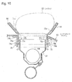
- Fig. 10 is a cross-sectional view of the airbag device in operation.
- Fig. 11 is a perspective view of a door frame of the airbag device.
- an airbag 52 ( Fig. 10 ) in a folded state is housed in a retainer 50 of an upper-opening container type and is inflatable by means of an inflator 54.
- the upper side of the retainer 50 is covered with an instrument panel 60.
- the instrument panel 60 is provided with recessed tear lines 62a and 62b.
- the tear line 62b extends along the upper rim of the retainer 50, and the inner region surrounded by this peripheral tear line 62b defines a door portion 64.
- the tear line 62a extends so as to traverse the middle of the door portion 64.
- a door frame 70 constituted by a movable door-frame member 72 and a stationary door-frame member 74.
- the stationary door-frame member 74 is rectangular and has the movable door-frame member 72 fitted therein in a slidable fashion.
- the movable door-frame member 72 has a backing plate 72a that underlies the door portion 64 of the instrument panel 60, and leg plates 72b extending downward in Fig. 9 from opposite edges of the backing plate 72a.
- the leg plates 72b are provided with hook holes 72c.
- the backing plate 72a has a tear line 72d in alignment with the tear line 62a.
- recessed hinge grooves 72e are provided along the edges where the backing plate 72a and the leg plates 72b meet.
- the backing plate 72a is fixed to the undersurface of the door portion 64 of the instrument panel 60 by vibration welding.
- the stationary door-frame member 74 includes a rectangular leg frame 74a serving as a leg portion that surrounds the outer periphery of the retainer 50, and a flange portion 74b that extends outward from the upper end of the leg frame 74a.
- the flange portion 74b is fixed to an area of the controller 60 surrounding the door portion 64 by vibration welding.
- the leg frame 74a is provided with hook holes 74c.
- the retainer 50 has uncinated hooks 78 fixed thereto, which are inserted through the hook holes 72c and 74c.
- the movable door-frame member 72 when the inflator 54 discharges gas, the movable door-frame member 72 is moved (lifted) upward by being pushed upward by the inflating airbag 52.
- the instrument panel 60 ruptures along the tear line 62b, causing the door portion 64 to be cut and separated from the surrounding instrument panel 60.
- the tear line 72d of the backing plate 72a and the tear line 62a of the door portion 64 become ruptured, thus causing the door portion 64 to open in the form of a door by being separated into two segments in the left and right directions in Fig. 10 .
- the airbag 52 deploys toward the vehicle interior.
- the door portion 64 lifted in this manner becomes separated from the surrounding instrument panel 60, the door portion 64 can be opened smoothly without receiving a deformation reaction force from the surrounding instrument panel 60.
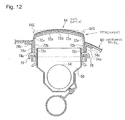
- Fig. 12 is a schematic cross-sectional view showing a state immediately after the start of the lifting operation.
- the airbag 52 pushes the door portion 64 so that an area near the central tear line 72d forms an upward projecting bulge.
- the door portion 64 of the instrument panel 60 is cut and separated from its surroundings and has a rectangular shape with a size substantially the same as that of the backing plate 72a. Since this rectangular door portion 64 tries to maintain its flatness with its own rigidity as shown with a dot-chain line, opposite edges 64S of the door portion 64 try to detach themselves from the backing plate 72a. This detachment tends to occur at corner sections of the backing plate 72a proximate to the leg plates 72b.
- the object of the present invention is to solve the aforementioned problems by providing an interior panel assembly and an airbag device that are equipped with means for preventing an interior panel and a backing plate from becoming detached from each other.
- An interior panel assembly includes an interior panel having a door portion through which an airbag passes and also includes a door frame for an airbag device, the door frame being fixed to an undersurface of the interior panel.
- the door frame includes a backing plate fixed to an undersurface of the door portion, and a leg portion connected to the backing plate and projecting from the undersurface of the interior panel.
- the door portion is openable toward a front side of the interior panel when the airbag inflates.
- a joint section between the backing plate and the leg portion or a vicinity of the joint section is provided with a rupturable section that allows the backing plate and the leg portion to become partially separated from each other when the door portion opens.
- the interior panel assembly according to Claim 2 is characterized in that, in Claim 1, the backing plate and the interior panel are fixed to each other by vibration welding.
- the interior panel assembly according to Claim 3 is characterized in that, in one of Claims 1 and 2, the door frame includes a stationary door-frame member and a movable door-frame member.
- the stationary door-frame member includes a rectangular tubular leg frame and a flange portion extending outward from the leg frame along the undersurface of the interior panel.
- the movable door-frame member includes a leg plate serving as the leg portion and movable along an inner surface of the leg frame, and the backing plate connected to the leg plate.
- the interior panel assembly according to Claim 4 is characterized in that, in Claims 1, 2 or 3, the rupturable section is defined by a groove that extends along the joint section between the backing plate and the leg plate.
- the interior panel assembly according to Claim 5 is characterized in that, in Claim 4, an end of the groove in an extending direction thereof is provided with a stopper that stops a rupture from spreading outward from the groove.
- the interior panel assembly according to Claim 6 is characterized in that, in Claim 5, the stopper is defined by a recessed hole connected to the end of the groove and having a substantially circular shape with a diameter larger than a width of the groove.
- the interior panel assembly according to Claim 7 is characterized in that, in one of Claims 4 to 6, one end of the groove is aligned with a rim of the movable door-frame member.
- An airbag device includes the interior panel assembly according to any one of Claims 1 to 7, an airbag disposed at an underside of the interior panel assembly, and an inflator for inflating the airbag.
- the joint section between the backing plate and the leg portion or the vicinity of the joint section is provided with a rupturable section.
- the rupturable section ruptures so that the backing plate and the leg portion become partially separated from each other.
- the backing plate becomes substantially flat as a result of the partial separation from the leg portion. In other words, the radius of curvature of the door portion at this separated section becomes smaller. As a result, this prevents the backing plate and the door portion from becoming detached from each other at the separated section.
- the backing plate and the interior panel are joined to each other by vibration welding so that the backing plate and the interior panel can be securely fixed to each other.
- the rupturable section is provided along the joint section between the backing plate and the leg plate serving as the leg portion of the movable door-frame member.
- the rupturable section ruptures and causes the backing plate to become partially separated from the leg plate.
- the backing plate becomes substantially flat as a result of the partial separation from the leg plate, thereby preventing the backing plate and the door portion from becoming detached from each other at the separated section.
- the rupturable section can be formed readily.
- the backing plate does not become entirely separated from the leg plate when the backing plate opens, thereby preventing the door portion from flying off.
- the stopper may be defined by a recessed hole connected to the end of the groove and having a substantially circular shape with a diameter larger than the width of the groove. In this way, the stopper can be formed readily.
- the groove By aligning one end of the groove with a rim of the movable door-frame member as in Claim 7, the groove can start to rupture smoothly.
- an instrument panel 20 has a central tear line 21 and a peripheral tear line 24 that are respectively similar to the tear lines 62a and 62b of the instrument panel 60 shown in Figs. 9 to 11 .
- the inner region of the peripheral tear line 24 defines a door portion 25.
- the peripheral tear line 24 extends to form a substantially rectangular shape.
- the central tear line 21 extends so as to connect intermediate points of the lateral sides of this rectangle to each other.
- the door frame 30 is constituted by movable door-frame members 32 and a stationary door-frame member 34.
- the stationary door-frame member 34 has a leg frame 34a of a substantially rectangular tubular shape having a pair of longitudinal walls and a pair of lateral walls, and a flange portion 34b extending outward from the leg frame 34a along the undersurface of the instrument panel 20.
- the movable door-frame members 32 have leg plates 32b that are movable along the inner surfaces of the longitudinal walls of the leg frame 34a, and backing plates 32a connected to the leg plates 32b and fixed to the undersurface of the instrument panel 20.
- recessed hinge grooves 32e are provided along the edges where the backing plates 32a and the leg plates 32b meet.
- movable door-frame members 32 there are two movable door-frame members 32 provided. Specifically, one of the movable door-frame members 32 is disposed along one of the longitudinal walls of the leg frame 34a, and the other movable door-frame member 32 is disposed along the other longitudinal wall of the leg frame 34a.
- the backing plates 32a of the two movable door-frame members 32 respectively underlie one half and the other half of the door portion 25 with respect to the central tear line 21 therebetween.
- Each movable door-frame member 32 has grooves 43 provided along the joint section between the backing plate 32a and the leg plate 32b.
- the grooves 43 serve as rupturable sections that partially separate the backing plate 32a and the leg plate 32b from each other when the backing plate 32a starts to open.
- the grooves 43 in each movable door-frame member 32 extend over a predetermined length at one end and the other end of the joint section between the backing plate 32a and the leg plate 32b in the extending direction thereof.
- each groove 43 is aligned with a rim of the corresponding movable door-frame member 32. Furthermore, in this embodiment, the other end of each groove 43 is provided with a substantially circular recessed hole 44 that serves as a stopper. Specifically, when the groove 43 ruptures, this recessed hole 44 serving as a stopper stops this rupture from spreading outward from the groove 43.
- the recessed hole 44 has a diameter that is larger than the width of the groove 43. This other end of the groove 43 is in communication with the recessed hole 44.
- each groove 43 has a length that is 5% to 30%, more preferably, 10% to 50% of the overall width of the joint section between the corresponding backing plate 32a and the corresponding leg plate 32b from one end to the other end of the joint section in the extending direction thereof.
- each groove 43 is formed along a salient edge where a surface of the corresponding backing plate 32a that faces the instrument panel 20 and a surface of the corresponding leg plate 32b that faces the leg frame 34a meet.
- each groove 43 is preferably disposed on the corresponding backing plate 32a or leg plate 32b within a range of 0 to 20 mm, more preferably, within a range of 0 to 10 mm from the corresponding salient edge.
- the grooves 43 may alternatively be disposed on the surfaces of the backing plates 32a that face away from the instrument panel 20, the surfaces of the leg plates 32b that face away from the leg frame 34a, or the edges where these surfaces meet.
- the pair of movable door-frame members 32 and 32 is fitted in the leg frame 34a in a manner such that the backing plates 32a and 32a are disposed with a gap therebetween.
- the backing plates 32a and 32a and the flange portion 34b of the stationary door-frame member 34 are pressed against the undersurface of the instrument panel 20 and are fixed thereto by vibration welding.
- the central tear line 21 of the instrument panel 20 is set between the backing plates 32a and 32a.
- the peripheral tear line 24 extends along the sides of the backing plates 32a and 32a.
- the leg plates 32b of the movable door-frame members 32 are provided with hook holes 32c.
- the hook holes 32c are long in the moving direction of the movable door-frame members 32 (i.e. a direction substantially orthogonal to the undersurface of the instrument panel 20).
- the leg frame 34a of the stationary door-frame member 34 is provided with hook holes 34c at positions where they coincide with the hook holes 32c.
- a retainer 10 has uncinated hooks 38 fixed thereto, which are inserted through the hook holes 32c and 34c.
- the leg frame 34a is disposed so as to surround the outer periphery of the retainer 10.
- the retainer 10 houses an airbag 12 in a folded state, which is inflatable by means of an inflator 14.
- the airbag 12 is attached to the retainer 10 by means of a mounting fitting 16.
- the airbag device operates in the following manner.
- the movable door-frame members 32 are moved (lifted) upward by being pushed upward by the inflating airbag 12.
- the hooks 38 move downward relatively within the hook holes 32c.
- the instrument panel 20 ruptures along the peripheral tear line 24, causing the door portion 25 to become cut and separated from the surrounding instrument panel 20.
- the airbag 12 pushes this separated door portion 25 so that an area near the central tear line 21 forms an upward projecting bulge.
- the opposite edges of the door portion 25 try to detach themselves from the backing plates 32a.
- the radius of curvature of the door portion 25 at the corner sections of the opposite edges of the backing plates 32a becomes smaller. As a result, this prevents the backing plates 32a and the door portion 25 from becoming detached from each other at the corner sections of the opposite edges of the backing plates 32a.
- the door portion 25 ruptures along the central tear line 21 in response to a pressing force from the airbag 12, whereby the door portion 25 opens in the form of a door by being separated into two segments together with the backing plates 32a and 32a in the left and right directions in Fig. 7 .
- the airbag 12 passes through between the separated segments of the opened door portion 25 so as to deploy toward the vehicle interior.
- each groove 43 since one end of each groove 43 is aligned with a rim of the corresponding movable door-frame member 32, the groove 43 ruptures immediately as the door portion 25 tries to recover its flatness from the curved state.
- the other end of each groove 43 is provided with a recessed hole 44 that serves as a stopper. Therefore, when the rupture of the groove 43 reaches the recessed hole 44, the recessed hole 44 spreads the shearing stress in order to stop the rupture. The rupture is thus prevented from spreading outward from the groove 43. Accordingly, when the backing plates 32a open, the backing plates 32a do not become entirely separated from the leg plates 32b, thereby preventing the door portion 25 from flying off.
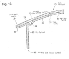
- Fig. 13 is a perspective view of one of joint sections between backing plates and leg plates of door frames of an interior panel assembly according to another embodiment.
- Door frames 80 included in the interior panel assembly each include a backing plate 81 fixed to the undersurface of the door portion 25 of the instrument panel 20, a leg portion 82 connected to one edge of the backing plate 81 via an allowance portion 84 to be described hereinafter and extending downward from the underside of the instrument panel 20, and a flange portion 83 extending along the undersurface of the instrument panel 20 from the upper edge of the leg portion 82 (upper edge in Fig. 13 ; the same applies hereinafter) in a direction away from the backing plate 81.
- the backing plate 81 and the leg portion 82 have a substantially U-shaped allowance portion 84 therebetween, which hangs downward from the undersurface of the instrument panel 20 so as to be separated therefrom.
- the one edge of the backing plate 81 and the upper edge of the leg portion 82 are connected to each other with the allowance portion 84.
- the allowance portion 84 functions as a connector between the backing plate 81 and the leg portion 82.
- grooves 85 that serve as rupturable sections extend along a salient edge where a surface of each backing plate 81 that faces the instrument panel 20 and a surface of each allowance portion 84 that faces the instrument panel 20 meet.
- the grooves 85 extend over a predetermined length at one end and the other end of the corresponding allowance portion 84 in the extending direction thereof.
- the grooves 85 serving as rupturable sections are not limited to those described above. Instead of the salient edges, the grooves 85 may be located on the surfaces of the backing plates 81 that face the instrument panel 20 or on the surfaces of the allowance portions 84 that face the instrument panel 20. Alternatively, the grooves 85 may be disposed on the surfaces of the backing plates 81 that face away from the instrument panel 20, the surfaces of the allowance portions 84 that face away from the instrument panel 20, or the edges where these surfaces meet. As a further alternative, the grooves 85 may be disposed on or near the edges of the allowance portions 84 proximate to the leg portions 82, or on or near the upper edges of the leg portions 82 connected to the allowance portions 84.
- the backing plates 81 of the two door frames 80 and 80 respectively underlie one half and the other half of the door portion 25 with respect to the central tear line 21 therebetween.
- the backing plates 81 and the flange portions 83 are fixed to the door portion 25 by vibration welding.
- the central tear line 21 is set between the backing plates 81 and 81 of the respective door frames 80 and 80.
- the peripheral tear line 24 is set so as to extend along joint sections between the backing plates 81 and the leg portions 82 of the door frames 80.
- the inflating airbag pushes the backing plates 81 upward and causes the allowance portions 84 to become stretched, thereby lifting the backing plates 81. Then, the instrument panel 20 ruptures along the peripheral tear line 24, causing the door portion 25 to become cut and separated from the surrounding instrument panel 20.
- the airbag pushes the separated door portion 25 so that an area near the central tear line 21 forms an upward projecting bulge.
- the door portion 25 tries to maintain its flatness with its own rigidity, the opposite edges of the door portion 25 (opposite edges as viewed in the horizontal direction in Fig. 13 ) try to detach themselves from the backing plates 81.
- the radius of curvature of the door portion 25 at the corner sections of the opposite edges of the backing plates 81 becomes smaller. As a result, this prevents the backing plates 81 and the door portion 25 from becoming detached from each other at the corner sections of the opposite edges of the backing plates 81.
- the door portion 25 ruptures along the central tear line 21 in response to a pressing force from the airbag, whereby the door portion 25 opens in the form of a door by being separated into two segments together with the backing plates 81 and 81 in the left and right directions in Fig. 13 .
- the airbag passes through between the separated segments of the opened door portion 25 so as to deploy toward the vehicle interior.
- the interior panel is defined by the instrument panel 20 in each of the above-described embodiments, the interior panel may alternatively be defined by, for example, a lid.
- a door frame is configured to allow a door portion of an interior panel to be lifted in response to a pressing force of an airbag generated at the time of inflation of an airbag.
- a door frame is not limited to this configuration.
- the present invention is applicable to an interior panel assembly equipped with a door frame of a type in which a door portion can be opened without being lifted.
Landscapes
- Engineering & Computer Science (AREA)
- Mechanical Engineering (AREA)
- Air Bags (AREA)
- Instrument Panels (AREA)
- Securing Of Glass Panes Or The Like (AREA)
Abstract
Description
- The present invention relates to airbag devices set in, for example, front of passenger's seats of vehicles, and particularly, to an airbag device whose door portion is lifted towards the vehicle interior during inflation of an airbag. The present invention also relates to an interior panel assembly used for such an airbag device.
- A typical passenger-seat airbag device set in a vehicle includes, for example, a folded airbag, a retainer to which the airbag is attached, an inflator (gas generator) for inflating the airbag, and an interior panel (such as an instrument panel or a lid) disposed in front of the retainer.
- When the inflator generates gas, the airbag starts to inflate and pushes open the interior panel. The interior panel ruptures along a tear line to allow the airbag to deploy to the vehicle interior, whereby the airbag restrains the occupant.
-
JP-A-2003-137054 -
Fig. 9 is a cross-sectional view of the airbag device disclosed inJP-A-2003-137054 Fig. 10 is a cross-sectional view of the airbag device in operation.Fig. 11 is a perspective view of a door frame of the airbag device. - Referring to
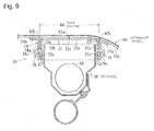
Fig. 9 , an airbag 52 (Fig. 10 ) in a folded state is housed in aretainer 50 of an upper-opening container type and is inflatable by means of aninflator 54. - The upper side of the
retainer 50 is covered with aninstrument panel 60. Theinstrument panel 60 is provided withrecessed tear lines tear line 62b extends along the upper rim of theretainer 50, and the inner region surrounded by thisperipheral tear line 62b defines adoor portion 64. On the other hand, thetear line 62a extends so as to traverse the middle of thedoor portion 64. - Under the
instrument panel 60 is provided adoor frame 70 constituted by a movable door-frame member 72 and a stationary door-frame member 74. The stationary door-frame member 74 is rectangular and has the movable door-frame member 72 fitted therein in a slidable fashion. - The movable door-
frame member 72 has abacking plate 72a that underlies thedoor portion 64 of theinstrument panel 60, andleg plates 72b extending downward inFig. 9 from opposite edges of thebacking plate 72a. Theleg plates 72b are provided withhook holes 72c. Thebacking plate 72a has atear line 72d in alignment with thetear line 62a. Along the edges where thebacking plate 72a and theleg plates 72b meet are providedrecessed hinge grooves 72e. - The
backing plate 72a is fixed to the undersurface of thedoor portion 64 of theinstrument panel 60 by vibration welding. - The stationary door-
frame member 74 includes arectangular leg frame 74a serving as a leg portion that surrounds the outer periphery of theretainer 50, and aflange portion 74b that extends outward from the upper end of theleg frame 74a. Theflange portion 74b is fixed to an area of thecontroller 60 surrounding thedoor portion 64 by vibration welding. Theleg frame 74a is provided withhook holes 74c. - The
retainer 50 has uncinatedhooks 78 fixed thereto, which are inserted through thehook holes - Referring to
Fig. 10 , when theinflator 54 discharges gas, the movable door-frame member 72 is moved (lifted) upward by being pushed upward by theinflating airbag 52. Theinstrument panel 60 ruptures along thetear line 62b, causing thedoor portion 64 to be cut and separated from the surroundinginstrument panel 60. As thedoor portion 64 is moved further upward together with the movable door-frame member 72 and is pushed upward by theairbag 52, thetear line 72d of thebacking plate 72a and thetear line 62a of thedoor portion 64 become ruptured, thus causing thedoor portion 64 to open in the form of a door by being separated into two segments in the left and right directions inFig. 10 . As a result, theairbag 52 deploys toward the vehicle interior. - Because the
door portion 64 lifted in this manner becomes separated from the surroundinginstrument panel 60, thedoor portion 64 can be opened smoothly without receiving a deformation reaction force from the surroundinginstrument panel 60. - In the airbag device shown in
Figs. 9 to 11 , when theairbag 52 inflates and lifts the movable door-frame member 72 upward, a large force that tries to detach thedoor portion 64 of theinstrument panel 60 from thebacking plate 72a acts on the joint sections between thebacking plate 72a and theleg plates 72b. - This phenomenon will be described with reference to
Fig. 12. Fig. 12 is a schematic cross-sectional view showing a state immediately after the start of the lifting operation. - Referring to
Fig. 12 , when the movable door-frame member 72 and thedoor portion 64 are being lifted, theairbag 52 pushes thedoor portion 64 so that an area near thecentral tear line 72d forms an upward projecting bulge. In this state, thedoor portion 64 of theinstrument panel 60 is cut and separated from its surroundings and has a rectangular shape with a size substantially the same as that of thebacking plate 72a. Since thisrectangular door portion 64 tries to maintain its flatness with its own rigidity as shown with a dot-chain line,opposite edges 64S of thedoor portion 64 try to detach themselves from thebacking plate 72a. This detachment tends to occur at corner sections of thebacking plate 72a proximate to theleg plates 72b. - In order to prevent such detachment of the
opposite edges 64S of thedoor portion 64, it is necessary to carefully attach theinstrument panel 60 and thebacking plate 72a to each other by vibration welding. For this reason, the vibration welding process and the management thereof are time consuming. - The object of the present invention is to solve the aforementioned problems by providing an interior panel assembly and an airbag device that are equipped with means for preventing an interior panel and a backing plate from becoming detached from each other.
- An interior panel assembly according to
Claim 1 includes an interior panel having a door portion through which an airbag passes and also includes a door frame for an airbag device, the door frame being fixed to an undersurface of the interior panel. The door frame includes a backing plate fixed to an undersurface of the door portion, and a leg portion connected to the backing plate and projecting from the undersurface of the interior panel. The door portion is openable toward a front side of the interior panel when the airbag inflates. A joint section between the backing plate and the leg portion or a vicinity of the joint section is provided with a rupturable section that allows the backing plate and the leg portion to become partially separated from each other when the door portion opens. - The interior panel assembly according to Claim 2 is characterized in that, in
Claim 1, the backing plate and the interior panel are fixed to each other by vibration welding. - The interior panel assembly according to Claim 3 is characterized in that, in one of
Claims 1 and 2, the door frame includes a stationary door-frame member and a movable door-frame member. In this case, the stationary door-frame member includes a rectangular tubular leg frame and a flange portion extending outward from the leg frame along the undersurface of the interior panel. The movable door-frame member includes a leg plate serving as the leg portion and movable along an inner surface of the leg frame, and the backing plate connected to the leg plate. - The interior panel assembly according to Claim 4 is characterized in that, in
Claims 1, 2 or 3, the rupturable section is defined by a groove that extends along the joint section between the backing plate and the leg plate. - The interior panel assembly according to Claim 5 is characterized in that, in Claim 4, an end of the groove in an extending direction thereof is provided with a stopper that stops a rupture from spreading outward from the groove.
- The interior panel assembly according to Claim 6 is characterized in that, in Claim 5, the stopper is defined by a recessed hole connected to the end of the groove and having a substantially circular shape with a diameter larger than a width of the groove.
- The interior panel assembly according to Claim 7 is characterized in that, in one of Claims 4 to 6, one end of the groove is aligned with a rim of the movable door-frame member.
- An airbag device according to Claim 8 includes the interior panel assembly according to any one of
Claims 1 to 7, an airbag disposed at an underside of the interior panel assembly, and an inflator for inflating the airbag. - In the airbag device and the interior panel assembly according to the present invention, the joint section between the backing plate and the leg portion or the vicinity of the joint section is provided with a rupturable section. When the door portion opens, the rupturable section ruptures so that the backing plate and the leg portion become partially separated from each other. At the section of the backing plate partially separated from the leg portion, the backing plate becomes substantially flat as a result of the partial separation from the leg portion. In other words, the radius of curvature of the door portion at this separated section becomes smaller. As a result, this prevents the backing plate and the door portion from becoming detached from each other at the separated section.
- As in Claim 2, the backing plate and the interior panel are joined to each other by vibration welding so that the backing plate and the interior panel can be securely fixed to each other.
- In Claim 3, when the airbag inflates, the movable door-frame member is lifted by being pushed by the inflating airbag, whereby the door portion becomes cut and separated from the surrounding interior panel. Accordingly, the door portion can be opened smoothly without receiving a deformation reaction force from the surrounding interior panel.
- In this case, the rupturable section is provided along the joint section between the backing plate and the leg plate serving as the leg portion of the movable door-frame member. When the backing plate is opened together with the door portion, the rupturable section ruptures and causes the backing plate to become partially separated from the leg plate. At the section of the backing plate partially separated from the leg plate, the backing plate becomes substantially flat as a result of the partial separation from the leg plate, thereby preventing the backing plate and the door portion from becoming detached from each other at the separated section.
- By providing a groove along the joint section between the backing plate and the leg plate as in Claim 4, the rupturable section can be formed readily.
- By providing a stopper at the end of the groove as in Claim 5 to prevent the rupture from spreading outward from the groove, the backing plate does not become entirely separated from the leg plate when the backing plate opens, thereby preventing the door portion from flying off.
- As in Claim 6, the stopper may be defined by a recessed hole connected to the end of the groove and having a substantially circular shape with a diameter larger than the width of the groove. In this way, the stopper can be formed readily.
- By aligning one end of the groove with a rim of the movable door-frame member as in Claim 7, the groove can start to rupture smoothly.
- Embodiments will now be described with reference to the drawings.
-
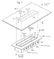
Fig. 1 is an exploded perspective view of an interior panel assembly according to an embodiment; -
Fig. 2 is an exploded perspective view of a door frame; -
Fig. 3 is a perspective view of a rupturable section of one of movable door-frame members and the vicinity thereof; -
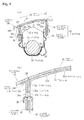
Fig. 4 includes an overall cross-sectional view (Fig. 4(a) ) and an enlarged view (Fig. 4(b) ; see area B inFig. 4(a) ) of an airbag device equipped with the interior panel assembly shown inFig. 1 ; -
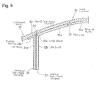
Fig. 5 is a cross-sectional view taken along line V-V inFig. 1 ; -
Fig. 6 is a cross-sectional view showing the same area asFig. 4(b) , and illustrates a state after the movable door-frame members are lifted and a pre-opened state of a door portion; -
Fig. 7 is a cross-sectional view showing the same area asFig. 4(a) and illustrates a state where the door portion has been opened; -
Fig. 8 is a cross-sectional view showing the same area asFig. 5 , and illustrates a state after the movable door-frame members are lifted and a pre-opened state of the door portion; -
Fig. 9 is a cross-sectional view of an airbag device of related art; -
Fig. 10 is a cross-sectional view of the airbag device shown inFig. 9 in operation; -
Fig. 11 is a perspective view of a door frame of the airbag device shown inFig. 9 ; -
Fig. 12 is a cross-sectional view of the airbag device shown inFig. 9 in operation; and -
Fig. 13 is a cross-sectional view of an interior panel assembly according to another embodiment. - Referring to
Fig. 1 , aninstrument panel 20 has acentral tear line 21 and aperipheral tear line 24 that are respectively similar to thetear lines instrument panel 60 shown inFigs. 9 to 11 . The inner region of theperipheral tear line 24 defines adoor portion 25. Theperipheral tear line 24 extends to form a substantially rectangular shape. Thecentral tear line 21 extends so as to connect intermediate points of the lateral sides of this rectangle to each other. - Under the
door portion 25 is provided adoor frame 30. In this embodiment, thedoor frame 30 is constituted by movable door-frame members 32 and a stationary door-frame member 34. - The stationary door-
frame member 34 has aleg frame 34a of a substantially rectangular tubular shape having a pair of longitudinal walls and a pair of lateral walls, and aflange portion 34b extending outward from theleg frame 34a along the undersurface of theinstrument panel 20. The movable door-frame members 32 haveleg plates 32b that are movable along the inner surfaces of the longitudinal walls of theleg frame 34a, andbacking plates 32a connected to theleg plates 32b and fixed to the undersurface of theinstrument panel 20. Along the edges where thebacking plates 32a and theleg plates 32b meet are provided recessedhinge grooves 32e. - In this embodiment, there are two movable door-
frame members 32 provided. Specifically, one of the movable door-frame members 32 is disposed along one of the longitudinal walls of theleg frame 34a, and the other movable door-frame member 32 is disposed along the other longitudinal wall of theleg frame 34a. Thebacking plates 32a of the two movable door-frame members 32 respectively underlie one half and the other half of thedoor portion 25 with respect to thecentral tear line 21 therebetween. - Each movable door-
frame member 32 hasgrooves 43 provided along the joint section between thebacking plate 32a and theleg plate 32b. Specifically, thegrooves 43 serve as rupturable sections that partially separate thebacking plate 32a and theleg plate 32b from each other when thebacking plate 32a starts to open. As shown inFig. 2 , in this embodiment, thegrooves 43 in each movable door-frame member 32 extend over a predetermined length at one end and the other end of the joint section between thebacking plate 32a and theleg plate 32b in the extending direction thereof. - Referring to
Fig. 3 , one end of eachgroove 43 is aligned with a rim of the corresponding movable door-frame member 32. Furthermore, in this embodiment, the other end of eachgroove 43 is provided with a substantially circular recessedhole 44 that serves as a stopper. Specifically, when thegroove 43 ruptures, this recessedhole 44 serving as a stopper stops this rupture from spreading outward from thegroove 43. The recessedhole 44 has a diameter that is larger than the width of thegroove 43. This other end of thegroove 43 is in communication with the recessedhole 44. - In this invention, each
groove 43 has a length that is 5% to 30%, more preferably, 10% to 50% of the overall width of the joint section between thecorresponding backing plate 32a and thecorresponding leg plate 32b from one end to the other end of the joint section in the extending direction thereof. - Referring to
Fig. 3 , in this embodiment, eachgroove 43 is formed along a salient edge where a surface of thecorresponding backing plate 32a that faces theinstrument panel 20 and a surface of thecorresponding leg plate 32b that faces theleg frame 34a meet. - The locations of the
grooves 43 serving as rupturable sections are not limited to those described above. Instead of the salient edges, thegrooves 43 may be located on the surfaces of thebacking plates 32a that face theinstrument panel 20 or on the surfaces of theleg plates 32b that face theleg frame 34a. In that case, eachgroove 43 is preferably disposed on thecorresponding backing plate 32a orleg plate 32b within a range of 0 to 20 mm, more preferably, within a range of 0 to 10 mm from the corresponding salient edge. In the present invention, thegrooves 43 may alternatively be disposed on the surfaces of thebacking plates 32a that face away from theinstrument panel 20, the surfaces of theleg plates 32b that face away from theleg frame 34a, or the edges where these surfaces meet. - The pair of movable door-
frame members leg frame 34a in a manner such that thebacking plates backing plates flange portion 34b of the stationary door-frame member 34 are pressed against the undersurface of theinstrument panel 20 and are fixed thereto by vibration welding. Thecentral tear line 21 of theinstrument panel 20 is set between thebacking plates peripheral tear line 24 extends along the sides of thebacking plates - The
leg plates 32b of the movable door-frame members 32 are provided withhook holes 32c. The hook holes 32c are long in the moving direction of the movable door-frame members 32 (i.e. a direction substantially orthogonal to the undersurface of the instrument panel 20). Theleg frame 34a of the stationary door-frame member 34 is provided withhook holes 34c at positions where they coincide with the hook holes 32c. - A
retainer 10 has uncinated hooks 38 fixed thereto, which are inserted through the hook holes 32c and 34c. Theleg frame 34a is disposed so as to surround the outer periphery of theretainer 10. - The
retainer 10 houses anairbag 12 in a folded state, which is inflatable by means of aninflator 14. Theairbag 12 is attached to theretainer 10 by means of a mountingfitting 16. - The airbag device operates in the following manner.
- Referring to
Figs. 6 and8 , when the inflator 14 discharges gas, the movable door-frame members 32 are moved (lifted) upward by being pushed upward by the inflatingairbag 12. During the lifting of the movable door-frame members 32, thehooks 38 move downward relatively within the hook holes 32c. In addition, theinstrument panel 20 ruptures along theperipheral tear line 24, causing thedoor portion 25 to become cut and separated from the surroundinginstrument panel 20. - As shown in
Figs. 6 and8 , theairbag 12 pushes this separateddoor portion 25 so that an area near thecentral tear line 21 forms an upward projecting bulge. However, since thedoor portion 25 tries to maintain its flatness with its own rigidity, the opposite edges of the door portion 25 (opposite edges as viewed in the horizontal direction inFigs. 6 and8 ) try to detach themselves from thebacking plates 32a. - In this case, a stress that tries to deform the
backing plates 32a into a flat shape is applied from thedoor portion 25 to thebacking plates 32a. This stress causes thegrooves 43 located at the opposite ends of the joint sections between thebacking plates 32a and theleg plates 32b to rupture, whereby the opposite edges of thebacking plates 32a (i.e. opposite edges as viewed in the extending direction of the joint sections between thebacking plates 32a and theleg plates 32b; the same applies hereinafter) become partially separated from theleg plates 32b. Consequently, at the corner sections of the opposite edges of thebacking plates 32a partially separated from theleg plates 32b, thebacking plates 32a become substantially flat as a result of the partial separation from theleg plates 32b. In other words, the radius of curvature of thedoor portion 25 at the corner sections of the opposite edges of thebacking plates 32a becomes smaller. As a result, this prevents thebacking plates 32a and thedoor portion 25 from becoming detached from each other at the corner sections of the opposite edges of thebacking plates 32a. - Subsequently, the
door portion 25 ruptures along thecentral tear line 21 in response to a pressing force from theairbag 12, whereby thedoor portion 25 opens in the form of a door by being separated into two segments together with thebacking plates Fig. 7 . As a result, theairbag 12 passes through between the separated segments of the openeddoor portion 25 so as to deploy toward the vehicle interior. - In this embodiment, since one end of each
groove 43 is aligned with a rim of the corresponding movable door-frame member 32, thegroove 43 ruptures immediately as thedoor portion 25 tries to recover its flatness from the curved state. In addition, the other end of eachgroove 43 is provided with a recessedhole 44 that serves as a stopper. Therefore, when the rupture of thegroove 43 reaches the recessedhole 44, the recessedhole 44 spreads the shearing stress in order to stop the rupture. The rupture is thus prevented from spreading outward from thegroove 43. Accordingly, when thebacking plates 32a open, thebacking plates 32a do not become entirely separated from theleg plates 32b, thereby preventing thedoor portion 25 from flying off. -
Fig. 13 is a perspective view of one of joint sections between backing plates and leg plates of door frames of an interior panel assembly according to another embodiment. - Door frames 80 included in the interior panel assembly according to this embodiment each include a
backing plate 81 fixed to the undersurface of thedoor portion 25 of theinstrument panel 20, aleg portion 82 connected to one edge of thebacking plate 81 via anallowance portion 84 to be described hereinafter and extending downward from the underside of theinstrument panel 20, and aflange portion 83 extending along the undersurface of theinstrument panel 20 from the upper edge of the leg portion 82 (upper edge inFig. 13 ; the same applies hereinafter) in a direction away from thebacking plate 81. - The
backing plate 81 and theleg portion 82 have a substantiallyU-shaped allowance portion 84 therebetween, which hangs downward from the undersurface of theinstrument panel 20 so as to be separated therefrom. In this embodiment, the one edge of thebacking plate 81 and the upper edge of theleg portion 82 are connected to each other with theallowance portion 84. Specifically, in this embodiment, theallowance portion 84 functions as a connector between thebacking plate 81 and theleg portion 82. When the airbag (not shown) inflates, eachdoor frame 80 receives a pressing force from the airbag and lifts thedoor portion 25 by stretching theallowance portion 84 toward the vehicle interior. - In this embodiment,
grooves 85 that serve as rupturable sections extend along a salient edge where a surface of eachbacking plate 81 that faces theinstrument panel 20 and a surface of eachallowance portion 84 that faces theinstrument panel 20 meet. In this embodiment, although not shown in detail, thegrooves 85 extend over a predetermined length at one end and the other end of thecorresponding allowance portion 84 in the extending direction thereof. - The locations of the
grooves 85 serving as rupturable sections are not limited to those described above. Instead of the salient edges, thegrooves 85 may be located on the surfaces of thebacking plates 81 that face theinstrument panel 20 or on the surfaces of theallowance portions 84 that face theinstrument panel 20. Alternatively, thegrooves 85 may be disposed on the surfaces of thebacking plates 81 that face away from theinstrument panel 20, the surfaces of theallowance portions 84 that face away from theinstrument panel 20, or the edges where these surfaces meet. As a further alternative, thegrooves 85 may be disposed on or near the edges of theallowance portions 84 proximate to theleg portions 82, or on or near the upper edges of theleg portions 82 connected to theallowance portions 84. - In this embodiment, the
backing plates 81 of the twodoor frames door portion 25 with respect to thecentral tear line 21 therebetween. Thebacking plates 81 and theflange portions 83 are fixed to thedoor portion 25 by vibration welding. Thecentral tear line 21 is set between thebacking plates respective door frames peripheral tear line 24 is set so as to extend along joint sections between thebacking plates 81 and theleg portions 82 of the door frames 80. - In this embodiment, when the airbag inflates, the inflating airbag pushes the
backing plates 81 upward and causes theallowance portions 84 to become stretched, thereby lifting thebacking plates 81. Then, theinstrument panel 20 ruptures along theperipheral tear line 24, causing thedoor portion 25 to become cut and separated from the surroundinginstrument panel 20. - The airbag pushes the separated
door portion 25 so that an area near thecentral tear line 21 forms an upward projecting bulge. However, since thedoor portion 25 tries to maintain its flatness with its own rigidity, the opposite edges of the door portion 25 (opposite edges as viewed in the horizontal direction inFig. 13 ) try to detach themselves from thebacking plates 81. - In this case, a stress that tries to deform the
backing plates 81 into a flat shape is applied from thedoor portion 25 to thebacking plates 81. This stress causes thegrooves 85 located at the opposite ends of the joint sections between thebacking plates 81 and theallowance portions 84 to rupture, whereby the opposite edges of the backing plates 81 (i.e. opposite edges as viewed in the extending direction of theallowance portions 84; the same applies hereinafter) become partially separated from theallowance portions 84. Consequently, at the corner sections of the opposite edges of thebacking plates 81 partially separated from theallowance portions 84, thebacking plates 81 become substantially flat as a result of the partial separation from theallowance portions 84. In other words, the radius of curvature of thedoor portion 25 at the corner sections of the opposite edges of thebacking plates 81 becomes smaller. As a result, this prevents thebacking plates 81 and thedoor portion 25 from becoming detached from each other at the corner sections of the opposite edges of thebacking plates 81. - Subsequently, the
door portion 25 ruptures along thecentral tear line 21 in response to a pressing force from the airbag, whereby thedoor portion 25 opens in the form of a door by being separated into two segments together with thebacking plates Fig. 13 . As a result, the airbag passes through between the separated segments of the openeddoor portion 25 so as to deploy toward the vehicle interior. - The above-described embodiments are only examples of the present invention, and the present invention is not limited to these embodiments.
- Although the interior panel is defined by the
instrument panel 20 in each of the above-described embodiments, the interior panel may alternatively be defined by, for example, a lid. - In each of the above-described embodiments, a door frame is configured to allow a door portion of an interior panel to be lifted in response to a pressing force of an airbag generated at the time of inflation of an airbag. However, a door frame is not limited to this configuration. The present invention is applicable to an interior panel assembly equipped with a door frame of a type in which a door portion can be opened without being lifted.
Claims (8)
- An interior panel assembly including an interior panel having a door portion through which an airbag passes and also including a door frame for an airbag device, the door frame being fixed to an undersurface of the interior panel,
wherein the door frame includes a backing plate fixed to an undersurface of the door portion, and a leg portion connected to the backing plate and projecting from the undersurface of the interior panel,
wherein the door portion is openable toward a front side of the interior panel when the airbag inflates, and
wherein a joint section between the backing plate and the leg portion or a vicinity of the joint section is provided with a rupturable section that allows the backing plate and the leg portion to become partially separated from each other when the door portion opens. - The interior panel assembly according to Claim 1, wherein the backing plate and the interior panel are fixed to each other by vibration welding.
- The interior panel assembly according to one of Claims 1 and 2, wherein the door frame includes a stationary door-frame member and a movable door-frame member,
wherein the stationary door-frame member includes a rectangular tubular leg frame and a flange portion extending outward from the leg frame along the undersurface of the interior panel, and
wherein the movable door-frame member includes a leg plate serving as the leg portion and movable along an inner surface of the leg frame, and the backing plate connected to the leg plate. - The interior panel assembly according to claim 1, 2 or 3, wherein the rupturable section comprises a groove that extends along the joint section between the backing plate and the leg plate.
- The interior panel assembly according to Claim 4, wherein an end of the groove in an extending direction thereof is provided with a stopper that stops a rupture from spreading outward from the groove.
- The interior panel assembly according to Claim 5, wherein the stopper comprises a recessed hole connected to the end of the groove and having a substantially circular shape with a diameter larger than a width of the groove.
- The interior panel assembly according to any one of Claims 4 to 6, wherein one end of the groove is aligned with a rim of the movable door-frame member.
- An airbag device comprising the interior panel assembly according to any one of Claims 1 to 7, an airbag disposed at an underside of the interior panel assembly, and an inflator for inflating the airbag.
Applications Claiming Priority (1)
| Application Number | Priority Date | Filing Date | Title |
|---|---|---|---|
| JP2007143687A JP5045243B2 (en) | 2007-05-30 | 2007-05-30 | Interior panel assembly and airbag device |
Publications (3)
| Publication Number | Publication Date |
|---|---|
| EP1997691A2 true EP1997691A2 (en) | 2008-12-03 |
| EP1997691A3 EP1997691A3 (en) | 2009-08-05 |
| EP1997691B1 EP1997691B1 (en) | 2011-03-09 |
Family
ID=39720486
Family Applications (1)
| Application Number | Title | Priority Date | Filing Date |
|---|---|---|---|
| EP08150606A Not-in-force EP1997691B1 (en) | 2007-05-30 | 2008-01-24 | Interior panel assembly and airbag device |
Country Status (5)
| Country | Link |
|---|---|
| US (1) | US7854447B2 (en) |
| EP (1) | EP1997691B1 (en) |
| JP (1) | JP5045243B2 (en) |
| CN (1) | CN101314351A (en) |
| DE (1) | DE602008005367D1 (en) |
Cited By (2)
| Publication number | Priority date | Publication date | Assignee | Title |
|---|---|---|---|---|
| FR2988664A1 (en) * | 2012-03-27 | 2013-10-04 | Peugeot Citroen Automobiles Sa | Safety device for airbag in e.g. car, has guidance unit adapted to be relocated partially from case during starting of inflation of airbag such that front wall is placed outside case and airbag part is guided away from case in direction |
| EP4640496A1 (en) * | 2024-04-25 | 2025-10-29 | Stellantis Auto SAS | Dual function bracket for an airbag protection device of a vehicle |
Families Citing this family (9)
| Publication number | Priority date | Publication date | Assignee | Title |
|---|---|---|---|---|
| US20090315303A1 (en) * | 2008-06-23 | 2009-12-24 | Harvey Matthew Ettinger | Mechanically attached laminated seamless airbag hinge system |
| CN103192789B (en) * | 2013-01-07 | 2015-07-08 | 浙江吉利汽车研究院有限公司杭州分公司 | Air bag frame connection structure |
| JP6178110B2 (en) * | 2013-05-13 | 2017-08-09 | スズキ株式会社 | Airbag device |
| FR3007346B1 (en) * | 2013-06-24 | 2016-11-04 | Visteon Global Tech Inc | HOUSING CLOSURE DEVICE FOR AIRBAG |
| KR20150014211A (en) * | 2013-07-29 | 2015-02-06 | 현대모비스 주식회사 | Airbag door |
| US9333937B1 (en) * | 2014-12-10 | 2016-05-10 | Autoliv Asp, Inc. | Airbag cover with stress relief features |
| US9452666B1 (en) * | 2015-03-12 | 2016-09-27 | John Suh | Cushioning assembly |
| JP2017114441A (en) * | 2015-12-25 | 2017-06-29 | 本田技研工業株式会社 | Airbag device |
| US9694780B1 (en) | 2016-03-17 | 2017-07-04 | Autoliv Asp, Inc. | Airbag cover with breakaway-resistant features |
Citations (1)
| Publication number | Priority date | Publication date | Assignee | Title |
|---|---|---|---|---|
| JP2003137054A (en) | 2001-10-30 | 2003-05-14 | Inoac Corp | Insert member of air bag door |
Family Cites Families (9)
| Publication number | Priority date | Publication date | Assignee | Title |
|---|---|---|---|---|
| US5433473A (en) * | 1991-04-26 | 1995-07-18 | Toyoda Gosei Co., Ltd. | Pad mounting structure for air bag device |
| JPH1143003A (en) * | 1997-05-02 | 1999-02-16 | Kansei Corp | Instrument panel |
| EP1151898B1 (en) * | 2000-04-28 | 2004-02-25 | Inoac Corporation | Tear structure of air bag door |
| JP2002220019A (en) | 2001-01-24 | 2002-08-06 | Inoac Corp | Structure for opening airbag door |
| US7093849B2 (en) * | 2002-09-24 | 2006-08-22 | Nihon Plast Co., Ltd. | Cover body for air bag apparatus |
| JP4242215B2 (en) * | 2003-06-25 | 2009-03-25 | 日本プラスト株式会社 | Cover for airbag device and airbag device |
| US7278654B2 (en) * | 2004-01-30 | 2007-10-09 | Collins & Aikman Products Co. | Stiffening frame for an integral tether and tearstop in an air bag door |
| EP1700756A3 (en) * | 2005-03-08 | 2006-11-08 | Takata Corporation | Cover for use in airbag apparatus, and airbag apparatus |
| JP2007062710A (en) * | 2005-03-08 | 2007-03-15 | Takata Corp | Cover for airbag device and air bag device |
-
2007
- 2007-05-30 JP JP2007143687A patent/JP5045243B2/en not_active Expired - Fee Related
-
2008
- 2008-01-24 EP EP08150606A patent/EP1997691B1/en not_active Not-in-force
- 2008-01-24 DE DE602008005367T patent/DE602008005367D1/en active Active
- 2008-03-14 US US12/048,344 patent/US7854447B2/en not_active Expired - Fee Related
- 2008-03-21 CN CNA2008100830825A patent/CN101314351A/en active Pending
Patent Citations (1)
| Publication number | Priority date | Publication date | Assignee | Title |
|---|---|---|---|---|
| JP2003137054A (en) | 2001-10-30 | 2003-05-14 | Inoac Corp | Insert member of air bag door |
Cited By (3)
| Publication number | Priority date | Publication date | Assignee | Title |
|---|---|---|---|---|
| FR2988664A1 (en) * | 2012-03-27 | 2013-10-04 | Peugeot Citroen Automobiles Sa | Safety device for airbag in e.g. car, has guidance unit adapted to be relocated partially from case during starting of inflation of airbag such that front wall is placed outside case and airbag part is guided away from case in direction |
| EP4640496A1 (en) * | 2024-04-25 | 2025-10-29 | Stellantis Auto SAS | Dual function bracket for an airbag protection device of a vehicle |
| FR3161633A1 (en) * | 2024-04-25 | 2025-10-31 | Stellantis Auto Sas | DUAL-FUNCTION MOUNTING BRACKET FOR AN AIRBAG VEHICLE PROTECTION DEVICE |
Also Published As
| Publication number | Publication date |
|---|---|
| EP1997691A3 (en) | 2009-08-05 |
| US7854447B2 (en) | 2010-12-21 |
| JP5045243B2 (en) | 2012-10-10 |
| EP1997691B1 (en) | 2011-03-09 |
| JP2008296690A (en) | 2008-12-11 |
| US20080296874A1 (en) | 2008-12-04 |
| DE602008005367D1 (en) | 2011-04-21 |
| CN101314351A (en) | 2008-12-03 |
Similar Documents
| Publication | Publication Date | Title |
|---|---|---|
| EP1997691B1 (en) | Interior panel assembly and airbag device | |
| EP1547877B1 (en) | Airbag device | |
| US7658408B2 (en) | Airbag assembly | |
| US8523223B2 (en) | Folding method of airbag | |
| US20130292928A1 (en) | Airbag and airbag device | |
| US20090295136A1 (en) | Passenger airbag apparatus | |
| EP1908648B1 (en) | Airbag device | |
| JPH03109149A (en) | Air bag device | |
| CN112009418B (en) | Side airbag device | |
| JP2006051907A (en) | Vehicle airbag device | |
| KR101301134B1 (en) | Airbag device | |
| US10077019B2 (en) | Vehicle airbag device | |
| JPH03186451A (en) | Retainer for air bag device | |
| EP1880906A1 (en) | Interior finishing panel assembly and air bag device | |
| EP2692590B1 (en) | Airbag device | |
| KR101966872B1 (en) | Folding Device for Preventing the Emblem from Escaping from the Airbag Module Cover for a Vehicle | |
| JP2014051251A (en) | Air bag device | |
| JP2003237512A (en) | Interior trim member for vehicle | |
| CN115697782B (en) | Airbag device for passenger seat and method for manufacturing airbag device for passenger seat | |
| WO2013094338A1 (en) | Airbag device and module cover thereof | |
| CN110949305B (en) | front body structure | |
| WO2013008854A1 (en) | Airbag device | |
| CN101423046B (en) | Vehicular instrument panel | |
| JP2009248610A (en) | Airbag door supporting structure | |
| JP2007145173A (en) | Door frame for airbag device, interior panel assembly and airbag device |
Legal Events
| Date | Code | Title | Description |
|---|---|---|---|
| PUAI | Public reference made under article 153(3) epc to a published international application that has entered the european phase |
Free format text: ORIGINAL CODE: 0009012 |
|
| AK | Designated contracting states |
Kind code of ref document: A2 Designated state(s): AT BE BG CH CY CZ DE DK EE ES FI FR GB GR HR HU IE IS IT LI LT LU LV MC MT NL NO PL PT RO SE SI SK TR |
|
| AX | Request for extension of the european patent |
Extension state: AL BA MK RS |
|
| PUAL | Search report despatched |
Free format text: ORIGINAL CODE: 0009013 |
|
| AK | Designated contracting states |
Kind code of ref document: A3 Designated state(s): AT BE BG CH CY CZ DE DK EE ES FI FR GB GR HR HU IE IS IT LI LT LU LV MC MT NL NO PL PT RO SE SI SK TR |
|
| AX | Request for extension of the european patent |
Extension state: AL BA MK RS |
|
| 17P | Request for examination filed |
Effective date: 20100118 |
|
| 17Q | First examination report despatched |
Effective date: 20100304 |
|
| AKX | Designation fees paid |
Designated state(s): DE FR GB |
|
| GRAP | Despatch of communication of intention to grant a patent |
Free format text: ORIGINAL CODE: EPIDOSNIGR1 |
|
| GRAS | Grant fee paid |
Free format text: ORIGINAL CODE: EPIDOSNIGR3 |
|
| GRAA | (expected) grant |
Free format text: ORIGINAL CODE: 0009210 |
|
| AK | Designated contracting states |
Kind code of ref document: B1 Designated state(s): DE FR GB |
|
| REG | Reference to a national code |
Ref country code: GB Ref legal event code: FG4D |
|
| REF | Corresponds to: |
Ref document number: 602008005367 Country of ref document: DE Date of ref document: 20110421 Kind code of ref document: P |
|
| REG | Reference to a national code |
Ref country code: DE Ref legal event code: R096 Ref document number: 602008005367 Country of ref document: DE Effective date: 20110421 |
|
| PLBE | No opposition filed within time limit |
Free format text: ORIGINAL CODE: 0009261 |
|
| STAA | Information on the status of an ep patent application or granted ep patent |
Free format text: STATUS: NO OPPOSITION FILED WITHIN TIME LIMIT |
|
| 26N | No opposition filed |
Effective date: 20111212 |
|
| REG | Reference to a national code |
Ref country code: DE Ref legal event code: R097 Ref document number: 602008005367 Country of ref document: DE Effective date: 20111212 |
|
| REG | Reference to a national code |
Ref country code: FR Ref legal event code: ST Effective date: 20120928 |
|
| PG25 | Lapsed in a contracting state [announced via postgrant information from national office to epo] |
Ref country code: FR Free format text: LAPSE BECAUSE OF NON-PAYMENT OF DUE FEES Effective date: 20120131 |
|
| PGFP | Annual fee paid to national office [announced via postgrant information from national office to epo] |
Ref country code: GB Payment date: 20140122 Year of fee payment: 7 |
|
| GBPC | Gb: european patent ceased through non-payment of renewal fee |
Effective date: 20150124 |
|
| PG25 | Lapsed in a contracting state [announced via postgrant information from national office to epo] |
Ref country code: GB Free format text: LAPSE BECAUSE OF NON-PAYMENT OF DUE FEES Effective date: 20150124 |
|
| REG | Reference to a national code |
Ref country code: DE Ref legal event code: R082 Ref document number: 602008005367 Country of ref document: DE Representative=s name: VOSSIUS & PARTNER PATENTANWAELTE RECHTSANWAELT, DE Ref country code: DE Ref legal event code: R081 Ref document number: 602008005367 Country of ref document: DE Owner name: JOYSON SAFETY SYSTEMS JAPAN K.K., JP Free format text: FORMER OWNER: TAKATA CORP., TOKIO/TOKYO, JP |
|
| PGFP | Annual fee paid to national office [announced via postgrant information from national office to epo] |
Ref country code: DE Payment date: 20200121 Year of fee payment: 13 |
|
| REG | Reference to a national code |
Ref country code: DE Ref legal event code: R119 Ref document number: 602008005367 Country of ref document: DE |
|
| PG25 | Lapsed in a contracting state [announced via postgrant information from national office to epo] |
Ref country code: DE Free format text: LAPSE BECAUSE OF NON-PAYMENT OF DUE FEES Effective date: 20210803 |