EP1997657B1 - Buse d'aération avec une pluralité de lamelles - Google Patents
Buse d'aération avec une pluralité de lamelles Download PDFInfo
- Publication number
- EP1997657B1 EP1997657B1 EP08008912A EP08008912A EP1997657B1 EP 1997657 B1 EP1997657 B1 EP 1997657B1 EP 08008912 A EP08008912 A EP 08008912A EP 08008912 A EP08008912 A EP 08008912A EP 1997657 B1 EP1997657 B1 EP 1997657B1
- Authority
- EP
- European Patent Office
- Prior art keywords
- roller
- snap
- lamella
- lamella roller
- segments
- Prior art date
- Legal status (The legal status is an assumption and is not a legal conclusion. Google has not performed a legal analysis and makes no representation as to the accuracy of the status listed.)
- Not-in-force
Links
Images

Classifications
-
- B—PERFORMING OPERATIONS; TRANSPORTING
- B60—VEHICLES IN GENERAL
- B60H—ARRANGEMENTS OF HEATING, COOLING, VENTILATING OR OTHER AIR-TREATING DEVICES SPECIALLY ADAPTED FOR PASSENGER OR GOODS SPACES OF VEHICLES
- B60H1/00—Heating, cooling or ventilating devices
- B60H1/00642—Control systems or circuits; Control members or indication devices for heating, cooling or ventilating devices
- B60H1/00664—Construction or arrangement of damper doors
- B60H1/00671—Damper doors moved by rotation; Grilles
- B60H1/00685—Damper doors moved by rotation; Grilles the door being a rotating disc or cylinder or part thereof
-
- F—MECHANICAL ENGINEERING; LIGHTING; HEATING; WEAPONS; BLASTING
- F24—HEATING; RANGES; VENTILATING
- F24F—AIR-CONDITIONING; AIR-HUMIDIFICATION; VENTILATION; USE OF AIR CURRENTS FOR SCREENING
- F24F13/00—Details common to, or for air-conditioning, air-humidification, ventilation or use of air currents for screening
- F24F13/02—Ducting arrangements
- F24F13/06—Outlets for directing or distributing air into rooms or spaces, e.g. ceiling air diffuser
- F24F13/075—Outlets for directing or distributing air into rooms or spaces, e.g. ceiling air diffuser having parallel rods or lamellae directing the outflow, e.g. the rods or lamellae being individually adjustable
-
- B—PERFORMING OPERATIONS; TRANSPORTING
- B60—VEHICLES IN GENERAL
- B60H—ARRANGEMENTS OF HEATING, COOLING, VENTILATING OR OTHER AIR-TREATING DEVICES SPECIALLY ADAPTED FOR PASSENGER OR GOODS SPACES OF VEHICLES
- B60H1/00—Heating, cooling or ventilating devices
- B60H1/00642—Control systems or circuits; Control members or indication devices for heating, cooling or ventilating devices
- B60H1/00664—Construction or arrangement of damper doors
- B60H2001/00721—Air deflecting or air directing means
-
- F—MECHANICAL ENGINEERING; LIGHTING; HEATING; WEAPONS; BLASTING
- F24—HEATING; RANGES; VENTILATING
- F24F—AIR-CONDITIONING; AIR-HUMIDIFICATION; VENTILATION; USE OF AIR CURRENTS FOR SCREENING
- F24F13/00—Details common to, or for air-conditioning, air-humidification, ventilation or use of air currents for screening
- F24F13/08—Air-flow control members, e.g. louvres, grilles, flaps or guide plates
- F24F13/10—Air-flow control members, e.g. louvres, grilles, flaps or guide plates movable, e.g. dampers
- F24F13/14—Air-flow control members, e.g. louvres, grilles, flaps or guide plates movable, e.g. dampers built up of tilting members, e.g. louvre
- F24F13/1486—Air-flow control members, e.g. louvres, grilles, flaps or guide plates movable, e.g. dampers built up of tilting members, e.g. louvre characterised by bearings, pivots or hinges
Definitions
- the invention relates to a lamellar roller with fins and for storage in an air nozzle body according to the preamble of claim 1.
- a lamella roller of the type mentioned is known to the skilled worker and familiar.
- Such a laminated roller is for example made DE 20 2004 002 552 U1 which is considered to be the closest prior art.
- a lamellar roller provided with inclined lamellae which is mounted in a nozzle body, wherein the pivot axis of the lamellae extends substantially parallel to the mutually substantially parallel pivot axes of the lamellae of a lamella bank.
- the lamellar bank is in turn part of an air nozzle and serves to deflect the direction of the air flow emerging from the air nozzle, which is mounted on the nozzle body, wherein the air nozzle has a mutually pivotably mounted and substantially parallel to each other extending fin.
- Air nozzles are thus available from the prior art, which combines the advantages of a lamella roller with those of an air nozzle with arranged lamellar banks.
- This known from the prior art lamination roller is easy to manufacture and can be easily assembled as a compact part. Nevertheless, it allows with appropriate orientation a comparatively large free flow cross section and a good air deflection in a plane transverse to its pivot axis.
- the lamellae mentioned here is in itself from the US 36 83 787 known.
- the lamella receptacle in the lamellar roller allows quick installation, but on the other hand also prevents the lamellae in the lamellae, for example, easily detach from the folding receptacle due to significant vibrations in the vehicle interior.
- the invention is therefore based on the object, a fin roller of the type mentioned according to the preamble of claim 1 so that on the one hand a rapid assembly of the slats is ensured in the lamellar roller and on the other hand given a secure attachment is.
- snap-in segments are arranged between the end faces of the lamellar roller, which each have a recess on the lamella side, into which the lamellae can be snapped force-locked and / or positively.
- An advantage of the invention is the fact that a simple lateral mounting of the bearing pin of the slats is given. In addition, it is ensured according to the invention that the slats are stored in the unopened state such that they can not be pushed out.
- the Einschnappsegment has an arm portion and within the recess, the arm part is provided with a bulge. Within the recess, a curvature is also formed according to the invention, wherein the recess between the bulge and curvature is arcuate.
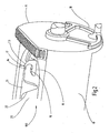
- FIG. 1 a lamella roller according to the invention is shown, which is provided with the reference numeral 100.
- the lamination roller 100 is part of an air nozzle and has two end faces 10, 11 and two side parts 19, 20.
- the lamination roller 100 also has Einschnappsegmente 12 for the storage of slats (not shown).
- Einschnappsegmente 12 have in FIG. 1 Not shown corresponding Einschnappsegmente, which are arranged along the side surface 19.
- the Einschnappsegmente 12 emerge from an edge 23 which is formed along the side parts 19, 20.
- Both the blades, not shown here, as well as the Einschnappsegmente 12 are formed as soft plastic molded parts.
- the Einschnappsegmente 12 each have a recess 14 into which the lamellae provided for the lamellae roller 100 are non-positively and / or positively latched.
- the lamellae can for this purpose have bearing journals which protrude from the lamellae in opposite directions and snap into the recesses 14.
- the Einschnappsegmente 12 are structurally configured such that they have an arm portion 15 which is formed elastically. In a terminology used here could therefore also speak of a spring arm.
- the arm part 15 is provided with a bulge 16.
- a curvature 17 is formed within the recess 14. This curvature is integrally formed in the edge 23 and is located within the recess 14 obliquely opposite the bulge 15.
- the recess 14 is formed between the bulge 16 and the bulge 17 arcuate.
- the arms of the arm part 15 (“spring arm”) extend in the embodiment shown here, with the exception of the arm part 16 of the snap-in segment 13 in the direction of the end face 11 provided with a setting wheel 18 for pivoting the lamellar roller 100.
- FIG. 2 shows that the next to the end face 11 Einschaltsegment 13 to the remaining Einschnappsegmenten 12 diametrically, that is arranged by 180 ° to the remaining Einschnappsegmenten 12. This arrangement is design-related in the embodiment shown here. Between the Einschnappsegment 13 and the next closest Einschnappsegment 12 a projection 21 is also arranged, but in the in FIG. 2 shown embodiment of the fin roller 100 of the invention, the recess 14 of the Einschnappsegments 13 facing side of the projection 21 is not formed obliquely.
- the present invention is not limited in its execution to the above-mentioned, preferred embodiments. Rather, a number of variants are conceivable, which make use of the illustrated solution even with fundamentally different types of execution. Thus, it is not necessary that the recesses take an arcuate course in their interior. Also, for example, the projections 21 may be configured differently.
Landscapes
- Engineering & Computer Science (AREA)
- Mechanical Engineering (AREA)
- Chemical & Material Sciences (AREA)
- Combustion & Propulsion (AREA)
- General Engineering & Computer Science (AREA)
- Physics & Mathematics (AREA)
- Thermal Sciences (AREA)
- Rolls And Other Rotary Bodies (AREA)
- Air-Conditioning For Vehicles (AREA)
Claims (13)
- Cylindre à lamelles avec des lamelles pour loger dans un corps de conduit d'air caractérisé en ce que des segments à encliquetage (12, 13) sont disposés entre les fronts (10, 11) du cylindre à lamelles (100), qui présentent respectivement sur le côté des lamelles un creux (14), dans lequel les lamelles sont emboîtables par encliquetage à engagement positif et/ou par adhérence.
- Cylindre à lamelles selon la revendication 1, caractérisé en ce que les segments encliquetables (12, 13) présentent une section à bras (15).
- Cylindre à lamelles selon l'une des revendications 1 ou 2, caractérisé en ce que la section à bras (15) est configuré élastique.
- Cylindre à lamelles selon lune des revendications 2 ou 3, caractérisé en ce que la section à bras (15) est munie d'une indentation (16) dans le creux (14).
- Cylindre à lamelles selon la revendication 1, caractérisé en ce qu'une voûte (17) est formée à lintérieur du creux (14), où le creux (14) est configuré en arc entre lindentation (16) et la voûte (17).
- Cylindre à lamelles selon lune des revendications 2 à 5, caractérisé en ce que les bras de la section à bras (15) s'étendent en direction du front (11) équipée d'une roue de position (18) pour la rotation du cylindre à lamelles (100).
- Cylindre à lamelles selon la revendication 6, caractérisé en ce que le segment à encliquetage (13) qui se trouve le plus proche du front (11) est disposé diamétralement opposé aux segments à encliquetage restants (12).
- Cylindre à lamelles selon lune des revendications précédentes, caractérisé en ce que les segments encliquetables (12) sont disposés des deux côtés du cylindre à lamelles (100) entre les fronts (10, 11).
- Cylindre à lamelles selon lune des revendications précédentes caractérisé en ce que des parties en saillie (21) sont disposées entre les segments encliquetables (12).
- Cylindre à lamelles selon la revendication 9, caractérisé en ce que la face (22) de la partie en saillie (21) tournée vers le creux (14) est configurée en diagonale.
- Cylindre à lamelles selon lune des revendications précédentes, caractérisé en ce que les lamelles et les segments encliquetables (12) sont configuréés comme au complet comme une même pièce préformée de matière plastique.
- Cylindre à lamelles selon lune des revendications précédentes, caractérisé en ce que les lamelles et les segments encliquetables (12) sont faits d'une matière plastique élastique non-rigide.
- Buse d'air de préférence pour la ventilation des véhicules, caractérisée par l'utilisation d'un cylindre à lamelles avec les caractéristiques de l'une des revendications 1 à 12.
Applications Claiming Priority (1)
| Application Number | Priority Date | Filing Date | Title |
|---|---|---|---|
| DE102007025506A DE102007025506A1 (de) | 2007-06-01 | 2007-06-01 | Lamellenwalze |
Publications (2)
| Publication Number | Publication Date |
|---|---|
| EP1997657A1 EP1997657A1 (fr) | 2008-12-03 |
| EP1997657B1 true EP1997657B1 (fr) | 2010-01-20 |
Family
ID=39719167
Family Applications (1)
| Application Number | Title | Priority Date | Filing Date |
|---|---|---|---|
| EP08008912A Not-in-force EP1997657B1 (fr) | 2007-06-01 | 2008-05-14 | Buse d'aération avec une pluralité de lamelles |
Country Status (3)
| Country | Link |
|---|---|
| US (1) | US20080318512A1 (fr) |
| EP (1) | EP1997657B1 (fr) |
| DE (2) | DE102007025506A1 (fr) |
Families Citing this family (2)
| Publication number | Priority date | Publication date | Assignee | Title |
|---|---|---|---|---|
| JP4453780B1 (ja) * | 2008-10-29 | 2010-04-21 | ダイキン工業株式会社 | 空気調和機 |
| USD788903S1 (en) * | 2014-07-27 | 2017-06-06 | Aurora Konrad G. Schulz Gmbh & Co. Kg | Defrost nozzle |
Family Cites Families (23)
| Publication number | Priority date | Publication date | Assignee | Title |
|---|---|---|---|---|
| US345690A (en) * | 1886-07-20 | George hates | ||
| US1393917A (en) * | 1917-10-01 | 1921-10-18 | Cadillac Motor Car Company | Air-flow-controlling mechanism for internal-combustion-engine radiators |
| US2623251A (en) * | 1949-11-28 | 1952-12-30 | Tocchetto Virgil Dante | Adjustable louver for venetian blinds |
| US2853935A (en) * | 1953-02-16 | 1958-09-30 | Hunter Fan And Ventilating Com | Air deflector |
| US2864301A (en) * | 1953-11-13 | 1958-12-16 | American Measuring Instr Corp | Louvering system |
| US3252398A (en) * | 1964-01-06 | 1966-05-24 | Eaton Mfg Co | Louver assembly |
| GB1177390A (en) * | 1967-09-26 | 1970-01-14 | Clear Hooters Ltd | Directional Air-discharging Nozzle for a Heating or Ventilating System |
| US3683787A (en) | 1970-12-07 | 1972-08-15 | Arthur P Cary | Air flow system with full control elliptical vane louvers |
| US4753288A (en) * | 1986-10-22 | 1988-06-28 | Kysor Industrial Corporation | Polymeric shutter assembly |
| US4892288A (en) * | 1988-11-14 | 1990-01-09 | Cary Products Co., Inc. | Air flow louver system |
| DE4244484C2 (de) * | 1992-12-30 | 2003-04-17 | Itw Ateco Gmbh | Rotationsdämpfer |
| GB9317047D0 (en) * | 1993-08-16 | 1993-09-29 | Unwin C N Ltds | Improvements relating to restraints for wheeled appliances |
| IT1279565B1 (it) * | 1995-05-26 | 1997-12-16 | Fiat Auto Spa | Bocchetta di aereazione regolabile per abitacoli di autovetture. |
| US6250012B1 (en) * | 1997-11-28 | 2001-06-26 | Ricci Tools Inc. | Louver assembly with multi-position louver adjusting control rod having clamping connecting arms |
| US6145251A (en) * | 1999-09-17 | 2000-11-14 | Ricci; Fernando | Adjustable shutter assembly and slat control mechanism using a control gear and gear engaging positioner |
| AT5483U1 (de) * | 2001-07-02 | 2002-07-25 | Avl List Gmbh | Jalousie zum verschliessen von öffnungen |
| US6948543B1 (en) * | 2003-08-19 | 2005-09-27 | Jose Maria Sans Folch | Assembly for retaining a louver of a vertical blind assembly in an operative position |
| DE202004002552U1 (de) * | 2004-02-19 | 2004-04-29 | Happich Fahrzeug- Und Industrieteile Gmbh | Vorrichtung zur Luftverteilung |
| US7500329B2 (en) * | 2004-09-02 | 2009-03-10 | Hunter Douglas Inc. | Operating system for a shutter type covering for architectural openings |
| US20060052050A1 (en) * | 2004-09-09 | 2006-03-09 | Dometic Corporation | Air distribution apparatus |
| US7392628B2 (en) * | 2005-01-06 | 2008-07-01 | Tapco International Corporation | Functional shutter |
| DE102006010388A1 (de) * | 2006-03-03 | 2007-09-06 | Aurora Konrad G. Schulz Gmbh & Co. Kg | Belüftungsvorrichtung |
| USD593673S1 (en) * | 2006-11-27 | 2009-06-02 | Firma Aurora Konrad G. Schulz Gmbh & Co. Kg | Air louver |
-
2007
- 2007-06-01 DE DE102007025506A patent/DE102007025506A1/de not_active Withdrawn
-
2008
- 2008-05-14 DE DE502008000326T patent/DE502008000326D1/de active Active
- 2008-05-14 EP EP08008912A patent/EP1997657B1/fr not_active Not-in-force
- 2008-05-30 US US12/156,453 patent/US20080318512A1/en not_active Abandoned
Also Published As
| Publication number | Publication date |
|---|---|
| DE102007025506A1 (de) | 2008-12-04 |
| US20080318512A1 (en) | 2008-12-25 |
| DE502008000326D1 (de) | 2010-03-11 |
| EP1997657A1 (fr) | 2008-12-03 |
Similar Documents
| Publication | Publication Date | Title |
|---|---|---|
| DE102011120915B4 (de) | Luftausströmer | |
| DE102012111849B4 (de) | Heck-Luftleitvorrichtung für ein Kraftfahrzeug | |
| EP2472050B1 (fr) | Procédé de fixation d'une toile flexible sur un arbre d'enroulement et store | |
| EP2736775B1 (fr) | Dispositif de raccordement pour la liaison articulée d'une raclette à un porte-balais et un adaptateur | |
| DE102008007469A1 (de) | Verlängerungsteil für eine Einlaufklappe, Einlaufklappe mit einem solchen Verlängerungsteil und Triebwerk mit einer Einlaufklappe | |
| EP1985508B1 (fr) | Elément de déformation absorbant l'énergie pour un véhicule | |
| EP2614974B1 (fr) | Système de store pour un véhicule automobile | |
| DE102017105568B4 (de) | Modulares Luftklappensystem | |
| EP0749378A1 (fr) | Raclette d'essuie-glace | |
| EP1835237B1 (fr) | Lamelle stockée et pouvant être pivotée dans une installation de lamelles dans un boîtier d'une tuyère d'air | |
| EP3427984B2 (fr) | Dispositif de protection d'habitacle de véhicule | |
| EP3321113B1 (fr) | Dispositif d'écoulement d'air | |
| DE102007053531A1 (de) | Rolloeinrichtung | |
| EP2602144B1 (fr) | Extrémité frontale d'un véhicule | |
| EP2179901B1 (fr) | Dispositif de raccordement pour la liaison articulée d'une lame d'essuyage conçue sous la forme d'une barre plate avec un bras d'essuyage | |
| EP2602137B1 (fr) | Dispositif de sortie d'air pour l'espace intérieur d'un véhicule automobile | |
| EP2520463B1 (fr) | Caisson de store à enrouleur et système de store à enrouleur | |
| EP1998999B2 (fr) | Composant d'admission d'air pour dispositif de climatisation d'un vehicule ferroviaire et vehicule ferroviaire equipe d'un composant d'admission d'air | |
| EP1997657A1 (fr) | Buse d'aération avec une pluralité de lamelles | |
| DE102010023528B4 (de) | Luftausströmvorrichtung für ein Fahrzeug | |
| DE60016116T2 (de) | Lüftungsgitter, insbesondere für Kraftfahrzeuge | |
| AT406700B (de) | Tür, insbesondere brandschutztür | |
| DE202008013781U1 (de) | Verschwenkbar gelagerte Lamelle in Luftdüsen | |
| WO2013010809A1 (fr) | Dispositif de support pour un actionneur de réglage d'un siège de véhicule | |
| EP1555381B1 (fr) | Lamelle pour diminuer ou diriger la lumière dans les bâtiments |
Legal Events
| Date | Code | Title | Description |
|---|---|---|---|
| PUAI | Public reference made under article 153(3) epc to a published international application that has entered the european phase |
Free format text: ORIGINAL CODE: 0009012 |
|
| AK | Designated contracting states |
Kind code of ref document: A1 Designated state(s): AT BE BG CH CY CZ DE DK EE ES FI FR GB GR HR HU IE IS IT LI LT LU LV MC MT NL NO PL PT RO SE SI SK TR |
|
| AX | Request for extension of the european patent |
Extension state: AL BA MK RS |
|
| 17P | Request for examination filed |
Effective date: 20090509 |
|
| GRAP | Despatch of communication of intention to grant a patent |
Free format text: ORIGINAL CODE: EPIDOSNIGR1 |
|
| AKX | Designation fees paid |
Designated state(s): DE FR GB IT NL |
|
| GRAS | Grant fee paid |
Free format text: ORIGINAL CODE: EPIDOSNIGR3 |
|
| GRAA | (expected) grant |
Free format text: ORIGINAL CODE: 0009210 |
|
| AK | Designated contracting states |
Kind code of ref document: B1 Designated state(s): DE FR GB IT NL |
|
| REG | Reference to a national code |
Ref country code: GB Ref legal event code: FG4D Free format text: NOT ENGLISH |
|
| REF | Corresponds to: |
Ref document number: 502008000326 Country of ref document: DE Date of ref document: 20100311 Kind code of ref document: P |
|
| REG | Reference to a national code |
Ref country code: NL Ref legal event code: T3 |
|
| PLBE | No opposition filed within time limit |
Free format text: ORIGINAL CODE: 0009261 |
|
| STAA | Information on the status of an ep patent application or granted ep patent |
Free format text: STATUS: NO OPPOSITION FILED WITHIN TIME LIMIT |
|
| 26N | No opposition filed |
Effective date: 20101021 |
|
| PGFP | Annual fee paid to national office [announced via postgrant information from national office to epo] |
Ref country code: GB Payment date: 20140530 Year of fee payment: 7 |
|
| PGFP | Annual fee paid to national office [announced via postgrant information from national office to epo] |
Ref country code: NL Payment date: 20140523 Year of fee payment: 7 Ref country code: IT Payment date: 20140527 Year of fee payment: 7 Ref country code: DE Payment date: 20140228 Year of fee payment: 7 Ref country code: FR Payment date: 20140516 Year of fee payment: 7 |
|
| REG | Reference to a national code |
Ref country code: DE Ref legal event code: R119 Ref document number: 502008000326 Country of ref document: DE |
|
| GBPC | Gb: european patent ceased through non-payment of renewal fee |
Effective date: 20150514 |
|
| PG25 | Lapsed in a contracting state [announced via postgrant information from national office to epo] |
Ref country code: IT Free format text: LAPSE BECAUSE OF NON-PAYMENT OF DUE FEES Effective date: 20150514 |
|
| REG | Reference to a national code |
Ref country code: NL Ref legal event code: MM Effective date: 20150601 |
|
| REG | Reference to a national code |
Ref country code: FR Ref legal event code: ST Effective date: 20160129 |
|
| PG25 | Lapsed in a contracting state [announced via postgrant information from national office to epo] |
Ref country code: GB Free format text: LAPSE BECAUSE OF NON-PAYMENT OF DUE FEES Effective date: 20150514 Ref country code: NL Free format text: LAPSE BECAUSE OF NON-PAYMENT OF DUE FEES Effective date: 20150601 Ref country code: DE Free format text: LAPSE BECAUSE OF NON-PAYMENT OF DUE FEES Effective date: 20151201 |
|
| PG25 | Lapsed in a contracting state [announced via postgrant information from national office to epo] |
Ref country code: FR Free format text: LAPSE BECAUSE OF NON-PAYMENT OF DUE FEES Effective date: 20150601 |