EP1997546A2 - Geometrisch variables Filterabflusskopfstück - Google Patents
Geometrisch variables Filterabflusskopfstück Download PDFInfo
- Publication number
- EP1997546A2 EP1997546A2 EP07022266A EP07022266A EP1997546A2 EP 1997546 A2 EP1997546 A2 EP 1997546A2 EP 07022266 A EP07022266 A EP 07022266A EP 07022266 A EP07022266 A EP 07022266A EP 1997546 A2 EP1997546 A2 EP 1997546A2
- Authority
- EP
- European Patent Office
- Prior art keywords
- header
- mold
- underdrain
- basin
- filter
- Prior art date
- Legal status (The legal status is an assumption and is not a legal conclusion. Google has not performed a legal analysis and makes no representation as to the accuracy of the status listed.)
- Withdrawn
Links
Images











Classifications
-
- B—PERFORMING OPERATIONS; TRANSPORTING
- B01—PHYSICAL OR CHEMICAL PROCESSES OR APPARATUS IN GENERAL
- B01D—SEPARATION
- B01D24/00—Filters comprising loose filtering material, i.e. filtering material without any binder between the individual particles or fibres thereof
- B01D24/02—Filters comprising loose filtering material, i.e. filtering material without any binder between the individual particles or fibres thereof with the filter bed stationary during the filtration
- B01D24/20—Filters comprising loose filtering material, i.e. filtering material without any binder between the individual particles or fibres thereof with the filter bed stationary during the filtration the filtering material being provided in an open container
- B01D24/24—Downward filtration, the container having distribution or collection headers or pervious conduits
-
- B—PERFORMING OPERATIONS; TRANSPORTING
- B01—PHYSICAL OR CHEMICAL PROCESSES OR APPARATUS IN GENERAL
- B01D—SEPARATION
- B01D24/00—Filters comprising loose filtering material, i.e. filtering material without any binder between the individual particles or fibres thereof
- B01D24/46—Regenerating the filtering material in the filter
- B01D24/4631—Counter-current flushing, e.g. by air
-
- B—PERFORMING OPERATIONS; TRANSPORTING
- B01—PHYSICAL OR CHEMICAL PROCESSES OR APPARATUS IN GENERAL
- B01D—SEPARATION
- B01D2201/00—Details relating to filtering apparatus
- B01D2201/44—Special measures allowing the even or uniform distribution of fluid along the length of a conduit
Definitions
- the invention relates to filtration systems.
- the invention relates to filter underdrain design and construction.
- Filtration systems are prevalent tools for filtering water and other liquids. Such systems typically include a basin containing a bed of particulate matter, also known as filtration media, through which travels the liquid to be filtered.
- the filtration media typically comprise one or more layers of sand, gravel, etc., of various types and sizes, which are well-known in the art.
- the filtration media are supported by an underdrain.
- the underdrain surface supporting the filter media typically includes orifices in fluid communication with minor passages leading to a lower chamber. These orifices are smaller than the size of the adjacent filtration media particles, so that the liquid can pass through the orifices, but the filter media cannot.
- the underdrain surface may also be implemented as a screen.
- Figure 1C illustrates a plan view of a prior art filter 100.
- the filter 100 includes laterals 110, lain in a basin 108.
- Figure 1A illustrates a view of filter 100 across one lateral at cross section A of Figure 1C .
- Figure 1B illustrates a view of filter 100 across all the laterals 110 at cross section B of Figure 1C .
- Each lateral's 110 top surfaces are joined together side-by-side between the basin walls 116 so that the combined top surfaces of the laterals form the top surface of the underdrain ( 104, Figures 1A-1B ).
- Each lateral 101 is connected to a header 106 along the length of the header 106 by a major passage 112.
- Each lateral 110 has a screen through which the filtered liquid may travel to reach the header 106 via its major passage 112.
- each header's 106 cross-sectional area has been the same along the length of header 106.
- unfiltered liquid is passed through the filtration media.
- the liquid travels through the spaces between filtration media particles, while impurities (i.e., suspended solids) in the liquid are trapped and thereby filtered out of the liquid.
- the filtered liquid may then be directed elsewhere for use or further treatment.
- the filtration media becomes blocked by the trapped impurities.
- filtration systems are typically cleaned by forcing liquid and/or air or another gas backwards through the filtration media, in a process known as backwashing.
- Backwashing is carried out by receiving water from a backwashing source 114 in the header 106 and distributing the water through the header 106 to each lateral 110.
- the backwash flows through the passages 112 to each lateral 110, out of the orifices (not shown) in each lateral, and backwards through the filtration media 102.
- backwash flow be uniformly distributed throughout the filter bed.
- a non-uniform backwash flow is problematic because too little flow provides little cleaning effect, while too much flow causes filter media to be carried upward and lost to disposal. Non-uniform backwashing may also cause mixing of the filtration media's layers and other undesirable effects.
- Non-uniform backwashing may be caused by unequal flow to each lateral 110.
- This unequal flow may be caused by pressure drops along the length of the header 106.
- the pressure drop is caused by the flow diverted to each lateral 110, and may be exacerbated by hydraulic losses in the header 106.
- Some prior art systems have addressed this problem by varying the size or shape of the passages through which the liquid travels from the header 106 to the lateral 110, thus controlling the differential pressure between the laterals.
- Other prior art systems have addressed this problem by reducing the pressure drop along the header 106 by geometrically varying the header cross section. Typically, this geometric variation has taken the form of decreasing the cross section, or tapering the header 106.
- Non-uniform backwashing may also be caused by a "shadowing" effect created by the fluid flowing around the header above the filtration media.
- An embedded header eliminates this shadowing by placing the header out of the fluid flow path.
- Prior art embedded headers have included standard pipes embedded in the basin wall or floor.
- the header's geometric variation is typically a decrease in cross section along the header.
- the header is formed inside a filter underdrain basin and is encapsulated by the basin wall or floor.
- Constructing the filter includes providing a basin form and a header mold. Constructing the filter further includes filling the basin form with concrete by pouring concrete. After the concrete cures, the header mold is kept in place. Although the header mold defines the header, it does not constitute the header. The basin wall or floor in which the header is embedded provides the structural support for the header. Thus, the mold need not be made to withstand the operating pressures the header will encounter, which allows greater flexibility and precision in forming the header.
- FIGS 1A-1C illustrate a prior art filter.
- FIGS. 2A-D illustrate a filter according to the present disclosure.
- Figures 3A-C illustrate a geometrically variable underdrain header according to the present disclosure.
- Figures 4A-C show a geometrically variable underdrain header according to the present disclosure.
- Figures 5A-D show a geometrically variable underdrain header according to the present disclosure.
- Figures 6A-D show a geometrically variable underdrain header whose cross section decreases continuously and non-linearly according to the present disclosure.
- Figures 7A-D show a geometrically variable underdrain header whose cross section decreases continuously and non-linearly along the length of the header according to the present disclosure.
- Figures 8A-C show a frusto-conical geometrically variable underdrain header according to the present disclosure.
- Figures 9A-B illustrate a circular filter according to the present disclosure.
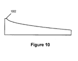
- Figure 10 illustrates a substantially continuous header with an initial boundary area.
- Figures 11A-D show an embedded geometrically variable underdrain header with an exposed upper surface flush with the floor of the basin.
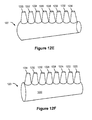
- Figures 12A-12F show a basin form and a geometrically variable underdrain header mold according to aspects of the present disclosure.
- Figures 13A-13E show the assembly of a basin form and a geometrically variable underdrain header mold according to aspects of the present disclosure.
- Figures 14A-B show construction methods for a geometrically variable underdrain header mold.
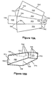
- Figures 15A-B show construction methods for a geometrically variable underdrain header mold.
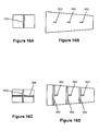
- Figures 16A-D show an internally reinforced geometrically variable underdrain header mold.
- Figures 17A-D show a geometrically variable underdrain header mold externally reinforced with rebar.
- Figures 18A-D show a construction method for steel sheets having channels.
- Figures 19A-C illustrates a method of manufacturing a header mold with an air pipe assembly.
- An embedded header is defined here as a header not protruding from the basin. Specific design details have been provided for illustration but should not be considered limiting. Readers of skill in the art will recognize that many variations of filter construction may be implemented consistent with the scope of the invention as described by the appended claims.
- filter 200 includes a basin 208, a filtration medium 102 disposed within the basin 208, and an underdrain 204 including a geometrically variable underdrain header 206.
- the geometrically variable underdrain header 206 is completely encapsulated the floor of the basin 208.
- Filter 200 could also be constructed such that the header is completely encapsulated in a wall of basin 208.
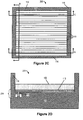
- FIG. 2C illustrates a plan view of the filter 200.
- Figure 2A illustrates a view across one lateral at cross section A.
- Figure 2B illustrates a view of filter 200 across all the laterals 110 at cross section B.
- Figure 2D illustrates a view of filter 200 across all the laterals 110 at cross section C.
- Filter 200 includes laterals 110 with a passage 112 connecting each lateral 110 to the geometrically variable underdrain header 206.
- the laterals are preferably Triton TM laterals manufactured by Johnson Screens and described in U.S. Patent 4,156,738 ("the '738 patent”), which is hereby incorporated by reference in its entirety. Laterals 110 and their installation are well-known prior art, thus such details are not repeated herein.
- the geometrically variable underdrain header 206 is an oblong passage configured so that the passage narrows along the length of the header 206, resulting in a continuously decreasing header cross section.
- the header cross section at C (shown in Figure 2D ) is smaller than the cross section at A (shown in Figure 2A ).
- the cross section's decrease is non-stepwise.
- the cross section of the header 206 may be defined by multiple flat sides.
- the cross section of the illustrated header 206 is four-sided, although the header 206 may have any number of flat or curved sides.
- the cross section, or at least one dimension of the cross-section (e.g., height, width, radius, etc.) may decrease linearly or non-linearly.
- Various header designs are illustrated in Figures 3-8 .
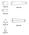
- Figures 3A-C illustrate a header cross section continuously decreasing in depth (d) along the length of the header 206.
- Figures 3A and 3C illustrate the cross section of each end of the header 206, while Figure 3B shows a side view.
- Figures 4A-C illustrate a triangular header cross section continuously and linearly decreasing in width (w) along the length of the header 206.
- Figures 4A and 4C illustrate the cross section of each end, while Figure 4B shows a top view of the same header 206.
- Figures 5A-D each illustrate a header 206 having a rectangular cross section decreasing in height (h) and width (w) along the length of the header.
- Figure 5A shows a sectional view of the wide end of the header 206.
- Figure 5B shows a sectional view of the narrow end of the header 206.
- Figure 5C shows a top view of the header 206.
- Figure 5D shows a side view of the header 206.
- Figures 6A-D show a header 206 where the cross section's rate of decrease along the length of the header increases.
- Figure 6A shows the end view of the wide end of the geometrically variable underdrain header 206.
- Figure 6B shows the end view of the narrow end of the geometrically variable underdrain header 206.
- Figure 6C shows the side view of the geometrically variable underdrain header 206.
- Figure 6D shows the top view of the geometrically variable underdrain header 206.
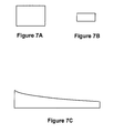
- Figures 7A-C illustrate a header where the cross section's rate of decrease along the length of the header decreases.
- Figure 7A shows the cross section of the wide end of the header 206.
- Figure 7B shows the narrow end.
- Figure 7C shows a side view of the geometrically variable underdrain header 206.
- the geometrically variable underdrain header 206 may be defined by a curved manifold that narrows along the length of the header 206.
- the header could also be a frusto-conical shell with a circular cross section of decreasing diameter (d), as shown by Figures 8A-C.
- Figure 8A shows a sectional view at the wide end of the geometrically variable underdrain header 206.
- Figure 8B shows a sectional view at the narrow end of the geometrically variable underdrain header 206.
- Figure 8C shows a perspective view of the geometrically variable underdrain header 206.
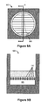
- FIGS 9A and 9B illustrate a plan view and a view across all the laterals 110 at cross section A, respectively, of a circular filter 900 with a header 906 having a cross section that decreases and then slightly increases in a semi-parabolic curve.
- headers 206 discussed above have continuously varying cross sections. These headers may be contrasted with a step-wise varying header, in which the changes in cross section are not continuous. It will be appreciated by those skilled in the art, however, that a header could be constructed with a short initial portion having one cross section and the remainder having a continuously decreasing cross section. Such headers will perform hydraulically very similarly to a truly continuously decreasing header, and thus should be considered substantially continuous.
- Figure 10 therefore illustrates a substantially continuous header with an initial boundary area 1002.
- FIGS 11A-D show an embedded geometrically variable underdrain header 1106 with an exposed upper surface 1108 flush with the floor 209 of the basin 208.
- Figure 11A shows an elevated perspective view of the embedded underdrain header 1106 and basin 208.
- Figure 11B shows a front perspective view of the embedded underdrain header 1106 and basin 208.
- Figure 11C shows a top view of embedded underdrain header 1106 and basin 208.
- Figure 11D shows a cross section of the embedded underdrain header 1106 and basin 208.
- the header may introduce a gas such as air into the lateral separately during backwashing.
- the underdrain header 1106 includes an air pipe assembly 1110 connected to an air source for supplying air to the lateral.
- the air pipe assembly 1110 includes an air distributor pipe 1112 attached to the interior of the underdrain header 1106 and multiple exit pipes 1114 running through the exposed upper surface 1108 in fluid communication with the interior 1116 of the air distributor pipe 1112 and the basin 208.
- the exit pipes 1114 each have slots 1118 in the portion of the exit pipe 1114 inside the air distributor pipe 1112.
- the slots 1118 connect the inside of an exit pipe with the exterior of the exit pipe for controlling an air plenum in the air distributor pipe 1112.
- the use of a slotted exit pipe to produce a plenum is well known in the art, and therefore is not discussed further.
- an air pipe assembly 1110 may also be implemented with any of the fully encapsulated underdrain header designs discussed above.
- Constructing a geometrically variable underdrain filter header 206 generally includes providing a basin form, disposing a geometrically variable underdrain header mold within the basin form, and pouring concrete in said basin form so as to encapsulate the header mold.
- Providing a basin form may be carried out by various known prior art techniques, including assembling the basin form on-site or positioning a prefabricated basin form in a desired location. This may include placing an inner basin form component inside an outer basin form component, as shown in Figure 12A .
- the basin form components may be made of wood, plastic, fiberglass, metal, or any other material that will occur to those of skill in the art.
- Figures 12B-D illustrate an exemplary basin form 1200 after assembly.
- Figure 12B shows a front view of basin form 1200.
- Figure 12C shows a side view of basin form 1200.
- Figure 12D shows a top view of basin form 1200.
- the outer basin form component 1200 has four outer sides 1202, and an outer floor 1204.
- the inner basin form component 1200 also includes four inner sides 1203 and an inner floor 1205 having openings 1212 for receiving the major passages of the header mold.
- the basin form 1200 also contains an opening 1206 for the header 206 to be coupled to a backwash media source 214. Alternatively, this can be done after the pour by connecting the backwash media source 214 to a flange on a header end protruding from the basin form 1200.
- Figures 12E-F show an exemplary geometrically variable underdrain header mold.
- the header mold 1201 may be formed in any of the header configurations discussed above.
- the mold 1201 includes a main header body 1236, and passages 1220-1234 for distributing the backwash media to the laterals (not shown).
- the interior surface of the mold 1201 may also include supports or turbulence minimization devices.
- the mold 1201 may also include a mechanism for connecting to the backwash media source, such as a flange.
- Figures 13A-C show header mold 1201 disposed within a basin form 1200.
- Figure 13A shows a front view of header mold 1201 within basin form 1200.
- Figures 13B and 13C show a side view and top view, respectively.
- the mold 1201 is disposed within the basin form 1200 in a position corresponding with the header's final position.
- the main body 1236 and passages 1220- 1234 are sealingly disposed in openings 1206 and 1212, respectively.
- the openings to main body 1236 and passages 1220-1234 are arranged so that no concrete enters the interior of mold 1201.
- An anchor 1238 may be attached to an appendage added to the mold 1201 for such a purpose or may be disposed about the mold 1201 itself, as shown in Figure 13D .
- the anchor 1238 is also attached to the basin form 1200.
- the header mold 1201 may be manufactured by many different processes and from many different materials.
- the header mold 1201 may be made from sheet steel. Because the concrete around the header mold 1201 forms the actual header structure, the mold for the header may be made from relatively thin (e . g ., 0.120-inch) polished steel sheets. This thinner steel is easier to cut, shape and weld than thicker steel. These polished steel sheets are readily available with a 2B finish, which provides a sufficient surface smoothness for the interior surface of the header 206. Using such sheets is more efficient and economical than traditional header manufacturing techniques, because no further treatment of the interior header surface is needed.
- Header mold 1201 may be made by cutting sheet metal to sides of the desired dimensions and welding the sides together to form a continuous shell as illustrated in Figures 14A-B.
- Figures 14A-B show the sides 1410-1520 before ( Figure 14A ) and after ( Figure 14B ) they are cut from a steel sheet 1406. Because the welds need only hold until the concrete cures, the mold may be fabricated using surface ("fill-in”) welds or skip welds instead of full-penetration welds. These lighter welds may be completed more quickly and provide a higher margin of error.
- Header mold 1201 may also be manufactured by cutting a sheet of steel to a desired pattern, and then pressing ( i . e ., folding) the cut sheet into the desired header form. The pressed sheet may then be welded at the seams to create a continuous shell as illustrated in Figures 15A-15B .
- Figures 15A-B show a cut steel sheet 1506 before ( Figure 15A ) and after ( Figure 15B ) it is folded along its edge lines 1544 and welded at its sheet edges 1542 to form a header mold 1201 with side panels 1510-1620.
- the folds at the sheet's 1506 edge lines 1544 become mold seams 1546, and welds at the sheet edges form mold seams 1548.
- the geometrically variable underdrain header 206 may be frusto-conical instead of multi-sided.
- a header mold may be constructed from one or more pieces of steel sheet pressed into a curvilinear shape to comprise at least a portion of frusto-conical mold and welded at the seams to create a continuous shell.
- the header could also be a spun concrete shell which may optionally be lined with fiberglass, plastic, or a similar material.
- header molds 1201 discussed above may be manufactured by extruding a plastic shell.
- Header mold 1201 may require additional support to prevent the mold from collapsing under the weight of the cement during the pour and before the cement cures. Once the cement cures, it is generally self-supporting, although header 206 may require additional support even after the cement has cured.
- This support may be interior, exterior, or both.
- Figures 16A-D show a header mold 1201 with support members attached to the interior.
- Figures 16A and 16B show a header mold 1201 with vertical columns 1602 attached to the interior of the mold 1201, from an end view and a top view, respectively.
- the vertical columns 1602 may be welded in place or otherwise attached to the interior. As illustrated, the vertical columns 1602 are shaped as vanes for turbulence minimization.
- the metal column of Figures 16A and 16B is shaped and positioned as a vane for minimizing turbulence in liquids traveling through the header by preventing the side-to-side flow of liquid in the header.
- Figure 16C and Figure 16D show a geometrically variable underdrain header mold 1201 with vertical columns 1602 and horizontal beams 1604 attached to the interior of the mold 1201, from an end view at the wide end of the mold and from a top sectional view, respectively.
- the horizontal beams 1604 in Figures 16C and 16D are also shaped as vanes for minimizing turbulence.
- the beams 1604 may be attached by any method used to attach the columns 1602.
- header mold 1201 may be externally reinforced.
- rebar is welded or otherwise attached to the outside of the mold.
- Figure 17A shows an end view of a header mold 1201 cross-sectionally reinforced with rebar.
- Figure 17B shows a top view of the same header mold 1201.
- the horizontal rebar 1702 and the vertical rebar 1704 are both welded to the outer surface of the mold 1201.
- the horizontal rebar 1702 and the vertical rebar 1704 are attached to each other at attachment points 1708.
- the rebar may be attached by welding, fasteners, or wound wire.
- a single section of rebar may be bent to conform to the shape of the mold 1201.
- Figures 17C and 17D show an end view and a top view, respectively, of cross-sectionally and longitudinally reinforced header mold 1201. Connection of the longitudinally reinforcing components may be the same as that of the cross sectional components.
- header mold 1201 may also be manufactured with features that promote the flow of poured concrete around the mold and that prevent the retention of air in the concrete around the mold. Such features may take the form of channels in the header.
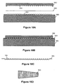
- Figures 18A-D illustrate a process of pressing channels into steel sheets during manufacturing of the geometrically variable underdrain header mold 901.
- Figure 18A shows a press in an open position for pressing channels into a steel sheet.
- the steel sheet 1804 is placed between the upper press plate 1802 and the lower press plate 1806.
- the lower press plate 1806 has peaks 1812 and the upper press plate 1804 has valleys 1814, which are brought together in a pressing action to form corrugations 1810 into the steel sheet 1804.
- Figure 18B shows a press in a closed position, after pressing channels into a steel sheet. After pressing, the pressed steel sheet 1808 has channels 1810. The pressed steel sheet 1808 may then be used in constructing a geometrically variable underdrain header mold 1201 according to the method disclosed above.
- Figure 18D below shows the side view of a geometrically variable underdrain header mold 1201 manufactured from one or more steel sheets 1804.
- Figures 19A-C illustrate a method of manufacturing a geometrically variable header mold 1201 with an air pipe assembly 1902 as discussed above.
- Figure 19A illustrates an exemplary header mold 1201 partially assembled.
- Figure 19B shows an exemplary air pipe assembly 1902.
- Figure 19C shows an exemplary air pipe assembly 1902 disposed within a header mold 1201.
- the interior of the header mold 1201 may be manufactured with an air pipe assembly 1902 by welding, gluing, or otherwise attaching an air distributor pipe 1904 to the interior 1906 of the header mold 1201.
- the header mold 1201 is positioned with multiple exit pipes 1908 disposed in ports 1910 in the top surface 1912 of the header mold 1201 so that the exit pipes 1908 are in fluid communication with the interior 1914 of the air distributor pipe 1904 and the area above the top surface 1912.
- the manufacture may further include sealing the annulus 1916 between each of the multiple exit pipes 1908 and the port 1910 in which it is disposed by welding, caulking, cementing and so on.
Landscapes
- Chemical & Material Sciences (AREA)
- Chemical Kinetics & Catalysis (AREA)
- Moulds, Cores, Or Mandrels (AREA)
- Sewage (AREA)
Applications Claiming Priority (1)
| Application Number | Priority Date | Filing Date | Title |
|---|---|---|---|
| US11/563,309 US20080121580A1 (en) | 2006-11-27 | 2006-11-27 | Geometrically Variable Filter Underdrain Header |
Publications (2)
| Publication Number | Publication Date |
|---|---|
| EP1997546A2 true EP1997546A2 (de) | 2008-12-03 |
| EP1997546A3 EP1997546A3 (de) | 2009-04-01 |
Family
ID=39462555
Family Applications (1)
| Application Number | Title | Priority Date | Filing Date |
|---|---|---|---|
| EP07022266A Withdrawn EP1997546A3 (de) | 2006-11-27 | 2007-11-16 | Geometrisch variables Filterabflusskopfstück |
Country Status (4)
| Country | Link |
|---|---|
| US (1) | US20080121580A1 (de) |
| EP (1) | EP1997546A3 (de) |
| AU (1) | AU2007211936A1 (de) |
| CA (1) | CA2599767A1 (de) |
Families Citing this family (3)
| Publication number | Priority date | Publication date | Assignee | Title |
|---|---|---|---|---|
| CA2901279C (en) * | 2013-02-15 | 2021-11-09 | Fabrice Jean Alphonse COURAGEOT | Underdrain assembly |
| CN110947211B (zh) * | 2019-11-29 | 2021-09-21 | 合肥三番水处理设备有限公司 | 一种彗星式纤维滤池 |
| JP2023537040A (ja) * | 2020-08-05 | 2023-08-30 | アクセプタンス グループ インコーポレイテッド | 形状決定された暗渠アセンブリを有するバイオフィルタ |
Citations (1)
| Publication number | Priority date | Publication date | Assignee | Title |
|---|---|---|---|---|
| US4156738A (en) | 1977-10-07 | 1979-05-29 | E. I. Du Pont De Nemours And Company | Ureidonitriles useful as antihypertensives |
Family Cites Families (12)
| Publication number | Priority date | Publication date | Assignee | Title |
|---|---|---|---|---|
| DE334113C (de) * | 1919-06-17 | 1921-03-09 | Eugen Steuer Dr | Verfahren und Vorrichtung zum Auswaschen von Filtermaterial durch Druckwasser und Gas (Luft) |
| US1358840A (en) * | 1919-12-24 | 1920-11-16 | Arthur L Gammage | Water-filter |
| US2745553A (en) * | 1951-11-16 | 1956-05-15 | Filtration Equipment Corp | Filter bottom for fixed bed filters |
| US2697520A (en) * | 1952-05-13 | 1954-12-21 | Ellila Karl Lauri | Method in making of filter apparatus |
| US4923606A (en) * | 1988-02-26 | 1990-05-08 | Tetra Technologies | Plastic-jacketed filter underdrain block |
| GB8808133D0 (en) * | 1988-04-07 | 1988-05-11 | Paterson Candy Int | Granular media filters |
| US5019259A (en) * | 1989-06-15 | 1991-05-28 | Hambley John B | Filter underdrain apparatus with partitioned distributor conduits |
| US5108627A (en) * | 1991-02-01 | 1992-04-28 | F.B. Leopold Company, Inc. | Filter underdrain block |
| US5156738A (en) * | 1991-06-21 | 1992-10-20 | Johnson Filtration Systems Inc. | Apparatus for uniformly distributing gas and/or liquid in an underdrain lateral system |
| US5160614A (en) * | 1992-02-25 | 1992-11-03 | The F.B. Leopold Company, Inc. | Air duct block for air/water underdrain systems in gravity filters |
| JP4354274B2 (ja) * | 2001-07-19 | 2009-10-28 | ウェザーフォード/ラム インコーポレーテッド | 分散/捕集システム |
| US6830684B2 (en) * | 2002-07-10 | 2004-12-14 | U.S. Filter Corporation | Integrated liquid and gas distribution device for underdrain block laterals |
-
2006
- 2006-11-27 US US11/563,309 patent/US20080121580A1/en not_active Abandoned
-
2007
- 2007-08-24 AU AU2007211936A patent/AU2007211936A1/en not_active Abandoned
- 2007-08-30 CA CA002599767A patent/CA2599767A1/en not_active Abandoned
- 2007-11-16 EP EP07022266A patent/EP1997546A3/de not_active Withdrawn
Patent Citations (1)
| Publication number | Priority date | Publication date | Assignee | Title |
|---|---|---|---|---|
| US4156738A (en) | 1977-10-07 | 1979-05-29 | E. I. Du Pont De Nemours And Company | Ureidonitriles useful as antihypertensives |
Also Published As
| Publication number | Publication date |
|---|---|
| US20080121580A1 (en) | 2008-05-29 |
| AU2007211936A1 (en) | 2008-06-12 |
| CA2599767A1 (en) | 2008-05-27 |
| EP1997546A3 (de) | 2009-04-01 |
Similar Documents
| Publication | Publication Date | Title |
|---|---|---|
| US11596878B2 (en) | Underdrain assembly and method of manufacturing same | |
| US6261453B1 (en) | Fluid treatment media support system | |
| CN103561843A (zh) | 扩展面积过滤器 | |
| CN103561842A (zh) | 具有内部支撑结构的扩展面积过滤器 | |
| EP1997546A2 (de) | Geometrisch variables Filterabflusskopfstück | |
| WO1995013123A1 (en) | Lateral underdrain | |
| US7063787B2 (en) | Filter media retaining cap and hold down grid | |
| US10730000B2 (en) | Filter assembly and methods | |
| US7922903B2 (en) | System and method for uniformly distributing a fluid through a filter bed in a filter | |
| US8992774B2 (en) | Flume system for a filter system including at least one filter having a filter bed that is periodically washed with liquid, gas or a combination thereof | |
| CN109513245B (zh) | 高精度免滤头的不锈钢滤池 | |
| KR102447756B1 (ko) | 유공블럭의 안정된 수밀구조와 균일한 분산구조를 갖는 딤플형 하부집수장치 | |
| US7736506B2 (en) | System and method for uniformly distributing a fluid through a filter bed in a filter | |
| WO2020206437A1 (en) | Filter screen having honeycomb support structure | |
| CN219423808U (zh) | 滤池 | |
| JPH05245314A (ja) | インライン型ストレーナ | |
| KR950003932Y1 (ko) | 중력식 급속 여과지의 블록 | |
| EP0788822B1 (de) | Flüssigkeitsfilter | |
| KR102788365B1 (ko) | 정수지(淨水池) 또는 배수지(配水池)에서 이물질 여과를 위한 여과장치 및 그 시공방법 | |
| JPH10216412A (ja) | フィルター | |
| CN113926243B (zh) | 径向过滤器 | |
| CA1313504C (en) | Filter underdrain system | |
| US4666601A (en) | Water filter | |
| US20030230542A1 (en) | Flow splitting weir | |
| WO2024081196A1 (en) | Method and system for anchoring an underdrain |
Legal Events
| Date | Code | Title | Description |
|---|---|---|---|
| PUAI | Public reference made under article 153(3) epc to a published international application that has entered the european phase |
Free format text: ORIGINAL CODE: 0009012 |
|
| 17P | Request for examination filed |
Effective date: 20071212 |
|
| AK | Designated contracting states |
Kind code of ref document: A2 Designated state(s): AT BE BG CH CY CZ DE DK EE ES FI FR GB GR HU IE IS IT LI LT LU LV MC MT NL PL PT RO SE SI SK TR |
|
| AX | Request for extension of the european patent |
Extension state: AL BA HR MK RS |
|
| PUAL | Search report despatched |
Free format text: ORIGINAL CODE: 0009013 |
|
| AK | Designated contracting states |
Kind code of ref document: A3 Designated state(s): AT BE BG CH CY CZ DE DK EE ES FI FR GB GR HU IE IS IT LI LT LU LV MC MT NL PL PT RO SE SI SK TR |
|
| AX | Request for extension of the european patent |
Extension state: AL BA HR MK RS |
|
| 17Q | First examination report despatched |
Effective date: 20090528 |
|
| AKX | Designation fees paid |
Designated state(s): BE FR GB |
|
| REG | Reference to a national code |
Ref country code: DE Ref legal event code: 8566 |
|
| STAA | Information on the status of an ep patent application or granted ep patent |
Free format text: STATUS: THE APPLICATION IS DEEMED TO BE WITHDRAWN |
|
| 18D | Application deemed to be withdrawn |
Effective date: 20091208 |