EP1997459A1 - Strukturelle Stent-/Faserkombinationen - Google Patents
Strukturelle Stent-/Faserkombinationen Download PDFInfo
- Publication number
- EP1997459A1 EP1997459A1 EP08251858A EP08251858A EP1997459A1 EP 1997459 A1 EP1997459 A1 EP 1997459A1 EP 08251858 A EP08251858 A EP 08251858A EP 08251858 A EP08251858 A EP 08251858A EP 1997459 A1 EP1997459 A1 EP 1997459A1
- Authority
- EP
- European Patent Office
- Prior art keywords
- segments
- fibres
- intraluminal
- radially expandable
- fibre
- Prior art date
- Legal status (The legal status is an assumption and is not a legal conclusion. Google has not performed a legal analysis and makes no representation as to the accuracy of the status listed.)
- Withdrawn
Links
- 239000000835 fiber Substances 0.000 title claims abstract description 47
- 108010035532 Collagen Proteins 0.000 claims abstract description 4
- 102000008186 Collagen Human genes 0.000 claims abstract description 4
- 229920001436 collagen Polymers 0.000 claims abstract description 4
- 239000000463 material Substances 0.000 claims description 32
- 239000003814 drug Substances 0.000 claims description 19
- 229940124597 therapeutic agent Drugs 0.000 claims description 18
- 229910001000 nickel titanium Inorganic materials 0.000 claims description 9
- 239000010935 stainless steel Substances 0.000 claims description 2
- WAIPAZQMEIHHTJ-UHFFFAOYSA-N [Cr].[Co] Chemical class [Cr].[Co] WAIPAZQMEIHHTJ-UHFFFAOYSA-N 0.000 claims 1
- 229910001220 stainless steel Inorganic materials 0.000 claims 1
- 239000000203 mixture Substances 0.000 abstract description 8
- 238000004873 anchoring Methods 0.000 abstract description 3
- 229920000642 polymer Polymers 0.000 description 17
- 238000000576 coating method Methods 0.000 description 14
- 239000011248 coating agent Substances 0.000 description 12
- 238000000034 method Methods 0.000 description 10
- 239000007943 implant Substances 0.000 description 7
- 230000008569 process Effects 0.000 description 7
- 239000002904 solvent Substances 0.000 description 7
- 239000003795 chemical substances by application Substances 0.000 description 6
- HLXZNVUGXRDIFK-UHFFFAOYSA-N nickel titanium Chemical compound [Ti].[Ti].[Ti].[Ti].[Ti].[Ti].[Ti].[Ti].[Ti].[Ti].[Ti].[Ni].[Ni].[Ni].[Ni].[Ni].[Ni].[Ni].[Ni].[Ni].[Ni].[Ni].[Ni].[Ni].[Ni] HLXZNVUGXRDIFK-UHFFFAOYSA-N 0.000 description 6
- 230000002401 inhibitory effect Effects 0.000 description 5
- -1 silk Polymers 0.000 description 5
- 239000000243 solution Substances 0.000 description 5
- RJURFGZVJUQBHK-UHFFFAOYSA-N actinomycin D Natural products CC1OC(=O)C(C(C)C)N(C)C(=O)CN(C)C(=O)C2CCCN2C(=O)C(C(C)C)NC(=O)C1NC(=O)C1=C(N)C(=O)C(C)=C2OC(C(C)=CC=C3C(=O)NC4C(=O)NC(C(N5CCCC5C(=O)N(C)CC(=O)N(C)C(C(C)C)C(=O)OC4C)=O)C(C)C)=C3N=C21 RJURFGZVJUQBHK-UHFFFAOYSA-N 0.000 description 4
- 229910045601 alloy Inorganic materials 0.000 description 4
- 239000000956 alloy Substances 0.000 description 4
- 239000003112 inhibitor Substances 0.000 description 4
- 239000000758 substrate Substances 0.000 description 4
- HZEWFHLRYVTOIW-UHFFFAOYSA-N [Ti].[Ni] Chemical compound [Ti].[Ni] HZEWFHLRYVTOIW-UHFFFAOYSA-N 0.000 description 3
- 230000001028 anti-proliverative effect Effects 0.000 description 3
- 238000005452 bending Methods 0.000 description 3
- 230000006835 compression Effects 0.000 description 3
- 238000007906 compression Methods 0.000 description 3
- 230000001965 increasing effect Effects 0.000 description 3
- 230000033001 locomotion Effects 0.000 description 3
- RZVAJINKPMORJF-UHFFFAOYSA-N Acetaminophen Chemical compound CC(=O)NC1=CC=C(O)C=C1 RZVAJINKPMORJF-UHFFFAOYSA-N 0.000 description 2
- BSYNRYMUTXBXSQ-UHFFFAOYSA-N Aspirin Chemical compound CC(=O)OC1=CC=CC=C1C(O)=O BSYNRYMUTXBXSQ-UHFFFAOYSA-N 0.000 description 2
- IJGRMHOSHXDMSA-UHFFFAOYSA-N Atomic nitrogen Chemical compound N#N IJGRMHOSHXDMSA-UHFFFAOYSA-N 0.000 description 2
- DLGOEMSEDOSKAD-UHFFFAOYSA-N Carmustine Chemical compound ClCCNC(=O)N(N=O)CCCl DLGOEMSEDOSKAD-UHFFFAOYSA-N 0.000 description 2
- PTOAARAWEBMLNO-KVQBGUIXSA-N Cladribine Chemical compound C1=NC=2C(N)=NC(Cl)=NC=2N1[C@H]1C[C@H](O)[C@@H](CO)O1 PTOAARAWEBMLNO-KVQBGUIXSA-N 0.000 description 2
- 108010092160 Dactinomycin Proteins 0.000 description 2
- AOJJSUZBOXZQNB-TZSSRYMLSA-N Doxorubicin Chemical compound O([C@H]1C[C@@](O)(CC=2C(O)=C3C(=O)C=4C=CC=C(C=4C(=O)C3=C(O)C=21)OC)C(=O)CO)[C@H]1C[C@H](N)[C@H](O)[C@H](C)O1 AOJJSUZBOXZQNB-TZSSRYMLSA-N 0.000 description 2
- 108050007372 Fibroblast Growth Factor Proteins 0.000 description 2
- 102000018233 Fibroblast Growth Factor Human genes 0.000 description 2
- XLYOFNOQVPJJNP-ZSJDYOACSA-N Heavy water Chemical compound [2H]O[2H] XLYOFNOQVPJJNP-ZSJDYOACSA-N 0.000 description 2
- HTTJABKRGRZYRN-UHFFFAOYSA-N Heparin Chemical compound OC1C(NC(=O)C)C(O)OC(COS(O)(=O)=O)C1OC1C(OS(O)(=O)=O)C(O)C(OC2C(C(OS(O)(=O)=O)C(OC3C(C(O)C(O)C(O3)C(O)=O)OS(O)(=O)=O)C(CO)O2)NS(O)(=O)=O)C(C(O)=O)O1 HTTJABKRGRZYRN-UHFFFAOYSA-N 0.000 description 2
- SIKJAQJRHWYJAI-UHFFFAOYSA-N Indole Chemical compound C1=CC=C2NC=CC2=C1 SIKJAQJRHWYJAI-UHFFFAOYSA-N 0.000 description 2
- DCXYFEDJOCDNAF-REOHCLBHSA-N L-asparagine Chemical compound OC(=O)[C@@H](N)CC(N)=O DCXYFEDJOCDNAF-REOHCLBHSA-N 0.000 description 2
- 208000031481 Pathologic Constriction Diseases 0.000 description 2
- 208000007536 Thrombosis Diseases 0.000 description 2
- 108010073929 Vascular Endothelial Growth Factor A Proteins 0.000 description 2
- 102000005789 Vascular Endothelial Growth Factors Human genes 0.000 description 2
- 108010019530 Vascular Endothelial Growth Factors Proteins 0.000 description 2
- 229960001138 acetylsalicylic acid Drugs 0.000 description 2
- 239000002253 acid Substances 0.000 description 2
- 150000007513 acids Chemical class 0.000 description 2
- RJURFGZVJUQBHK-IIXSONLDSA-N actinomycin D Chemical compound C[C@H]1OC(=O)[C@H](C(C)C)N(C)C(=O)CN(C)C(=O)[C@@H]2CCCN2C(=O)[C@@H](C(C)C)NC(=O)[C@H]1NC(=O)C1=C(N)C(=O)C(C)=C2OC(C(C)=CC=C3C(=O)N[C@@H]4C(=O)N[C@@H](C(N5CCC[C@H]5C(=O)N(C)CC(=O)N(C)[C@@H](C(C)C)C(=O)O[C@@H]4C)=O)C(C)C)=C3N=C21 RJURFGZVJUQBHK-IIXSONLDSA-N 0.000 description 2
- 210000003484 anatomy Anatomy 0.000 description 2
- 230000002927 anti-mitotic effect Effects 0.000 description 2
- 238000013459 approach Methods 0.000 description 2
- 230000004888 barrier function Effects 0.000 description 2
- 230000008901 benefit Effects 0.000 description 2
- 230000015572 biosynthetic process Effects 0.000 description 2
- 239000000109 continuous material Substances 0.000 description 2
- 229960000640 dactinomycin Drugs 0.000 description 2
- 229940088598 enzyme Drugs 0.000 description 2
- 229940126864 fibroblast growth factor Drugs 0.000 description 2
- 239000012530 fluid Substances 0.000 description 2
- JYGXADMDTFJGBT-VWUMJDOOSA-N hydrocortisone Chemical compound O=C1CC[C@]2(C)[C@H]3[C@@H](O)C[C@](C)([C@@](CC4)(O)C(=O)CO)[C@@H]4[C@@H]3CCC2=C1 JYGXADMDTFJGBT-VWUMJDOOSA-N 0.000 description 2
- 238000002513 implantation Methods 0.000 description 2
- CGIGDMFJXJATDK-UHFFFAOYSA-N indomethacin Chemical compound CC1=C(CC(O)=O)C2=CC(OC)=CC=C2N1C(=O)C1=CC=C(Cl)C=C1 CGIGDMFJXJATDK-UHFFFAOYSA-N 0.000 description 2
- 229910052751 metal Inorganic materials 0.000 description 2
- 239000002184 metal Substances 0.000 description 2
- CFCUWKMKBJTWLW-BKHRDMLASA-N mithramycin Chemical compound O([C@@H]1C[C@@H](O[C@H](C)[C@H]1O)OC=1C=C2C=C3C[C@H]([C@@H](C(=O)C3=C(O)C2=C(O)C=1C)O[C@@H]1O[C@H](C)[C@@H](O)[C@H](O[C@@H]2O[C@H](C)[C@H](O)[C@H](O[C@@H]3O[C@H](C)[C@@H](O)[C@@](C)(O)C3)C2)C1)[C@H](OC)C(=O)[C@@H](O)[C@@H](C)O)[C@H]1C[C@@H](O)[C@H](O)[C@@H](C)O1 CFCUWKMKBJTWLW-BKHRDMLASA-N 0.000 description 2
- PXHVJJICTQNCMI-UHFFFAOYSA-N nickel Substances [Ni] PXHVJJICTQNCMI-UHFFFAOYSA-N 0.000 description 2
- 230000035515 penetration Effects 0.000 description 2
- BASFCYQUMIYNBI-UHFFFAOYSA-N platinum Chemical compound [Pt] BASFCYQUMIYNBI-UHFFFAOYSA-N 0.000 description 2
- 229960003171 plicamycin Drugs 0.000 description 2
- ZAHRKKWIAAJSAO-UHFFFAOYSA-N rapamycin Natural products COCC(O)C(=C/C(C)C(=O)CC(OC(=O)C1CCCCN1C(=O)C(=O)C2(O)OC(CC(OC)C(=CC=CC=CC(C)CC(C)C(=O)C)C)CCC2C)C(C)CC3CCC(O)C(C3)OC)C ZAHRKKWIAAJSAO-UHFFFAOYSA-N 0.000 description 2
- 229960002930 sirolimus Drugs 0.000 description 2
- QFJCIRLUMZQUOT-HPLJOQBZSA-N sirolimus Chemical compound C1C[C@@H](O)[C@H](OC)C[C@@H]1C[C@@H](C)[C@H]1OC(=O)[C@@H]2CCCCN2C(=O)C(=O)[C@](O)(O2)[C@H](C)CC[C@H]2C[C@H](OC)/C(C)=C/C=C/C=C/[C@@H](C)C[C@@H](C)C(=O)[C@H](OC)[C@H](O)/C(C)=C/[C@@H](C)C(=O)C1 QFJCIRLUMZQUOT-HPLJOQBZSA-N 0.000 description 2
- 238000009987 spinning Methods 0.000 description 2
- 230000036262 stenosis Effects 0.000 description 2
- 208000037804 stenosis Diseases 0.000 description 2
- 229910052715 tantalum Inorganic materials 0.000 description 2
- GUVRBAGPIYLISA-UHFFFAOYSA-N tantalum atom Chemical compound [Ta] GUVRBAGPIYLISA-UHFFFAOYSA-N 0.000 description 2
- 230000001225 therapeutic effect Effects 0.000 description 2
- WYWHKKSPHMUBEB-UHFFFAOYSA-N tioguanine Chemical compound N1C(N)=NC(=S)C2=C1N=CN2 WYWHKKSPHMUBEB-UHFFFAOYSA-N 0.000 description 2
- 230000002792 vascular Effects 0.000 description 2
- 210000005166 vasculature Anatomy 0.000 description 2
- FPVKHBSQESCIEP-UHFFFAOYSA-N (8S)-3-(2-deoxy-beta-D-erythro-pentofuranosyl)-3,6,7,8-tetrahydroimidazo[4,5-d][1,3]diazepin-8-ol Natural products C1C(O)C(CO)OC1N1C(NC=NCC2O)=C2N=C1 FPVKHBSQESCIEP-UHFFFAOYSA-N 0.000 description 1
- FDKXTQMXEQVLRF-ZHACJKMWSA-N (E)-dacarbazine Chemical compound CN(C)\N=N\c1[nH]cnc1C(N)=O FDKXTQMXEQVLRF-ZHACJKMWSA-N 0.000 description 1
- 102100025573 1-alkyl-2-acetylglycerophosphocholine esterase Human genes 0.000 description 1
- VSNHCAURESNICA-NJFSPNSNSA-N 1-oxidanylurea Chemical compound N[14C](=O)NO VSNHCAURESNICA-NJFSPNSNSA-N 0.000 description 1
- FUFLCEKSBBHCMO-UHFFFAOYSA-N 11-dehydrocorticosterone Natural products O=C1CCC2(C)C3C(=O)CC(C)(C(CC4)C(=O)CO)C4C3CCC2=C1 FUFLCEKSBBHCMO-UHFFFAOYSA-N 0.000 description 1
- CTRPRMNBTVRDFH-UHFFFAOYSA-N 2-n-methyl-1,3,5-triazine-2,4,6-triamine Chemical class CNC1=NC(N)=NC(N)=N1 CTRPRMNBTVRDFH-UHFFFAOYSA-N 0.000 description 1
- PLIKAWJENQZMHA-UHFFFAOYSA-N 4-aminophenol Chemical class NC1=CC=C(O)C=C1 PLIKAWJENQZMHA-UHFFFAOYSA-N 0.000 description 1
- VHRSUDSXCMQTMA-UWKORSIYSA-N 6-methylprednisolone Chemical compound C([C@@]12C)=CC(=O)C=C1C(C)C[C@@H]1[C@@H]2[C@@H](O)C[C@]2(C)[C@@](O)(C(=O)CO)CC[C@H]21 VHRSUDSXCMQTMA-UWKORSIYSA-N 0.000 description 1
- STQGQHZAVUOBTE-UHFFFAOYSA-N 7-Cyan-hept-2t-en-4,6-diinsaeure Natural products C1=2C(O)=C3C(=O)C=4C(OC)=CC=CC=4C(=O)C3=C(O)C=2CC(O)(C(C)=O)CC1OC1CC(N)C(O)C(C)O1 STQGQHZAVUOBTE-UHFFFAOYSA-N 0.000 description 1
- 108010024976 Asparaginase Proteins 0.000 description 1
- XHVAWZZCDCWGBK-WYRLRVFGSA-M Aurothioglucose Chemical compound OC[C@H]1O[C@H](S[Au])[C@H](O)[C@@H](O)[C@@H]1O XHVAWZZCDCWGBK-WYRLRVFGSA-M 0.000 description 1
- NOWKCMXCCJGMRR-UHFFFAOYSA-N Aziridine Chemical class C1CN1 NOWKCMXCCJGMRR-UHFFFAOYSA-N 0.000 description 1
- 239000005552 B01AC04 - Clopidogrel Substances 0.000 description 1
- 239000005528 B01AC05 - Ticlopidine Substances 0.000 description 1
- 108010006654 Bleomycin Proteins 0.000 description 1
- 229940123587 Cell cycle inhibitor Drugs 0.000 description 1
- JWBOIMRXGHLCPP-UHFFFAOYSA-N Chloditan Chemical compound C=1C=CC=C(Cl)C=1C(C(Cl)Cl)C1=CC=C(Cl)C=C1 JWBOIMRXGHLCPP-UHFFFAOYSA-N 0.000 description 1
- 229910000531 Co alloy Inorganic materials 0.000 description 1
- MFYSYFVPBJMHGN-UHFFFAOYSA-N Cortisone Natural products O=C1CCC2(C)C3C(=O)CC(C)(C(CC4)(O)C(=O)CO)C4C3CCC2=C1 MFYSYFVPBJMHGN-UHFFFAOYSA-N 0.000 description 1
- MFYSYFVPBJMHGN-ZPOLXVRWSA-N Cortisone Chemical compound O=C1CC[C@]2(C)[C@H]3C(=O)C[C@](C)([C@@](CC4)(O)C(=O)CO)[C@@H]4[C@@H]3CCC2=C1 MFYSYFVPBJMHGN-ZPOLXVRWSA-N 0.000 description 1
- 102000016736 Cyclin Human genes 0.000 description 1
- 108050006400 Cyclin Proteins 0.000 description 1
- CMSMOCZEIVJLDB-UHFFFAOYSA-N Cyclophosphamide Chemical compound ClCCN(CCCl)P1(=O)NCCCO1 CMSMOCZEIVJLDB-UHFFFAOYSA-N 0.000 description 1
- PMATZTZNYRCHOR-CGLBZJNRSA-N Cyclosporin A Chemical compound CC[C@@H]1NC(=O)[C@H]([C@H](O)[C@H](C)C\C=C\C)N(C)C(=O)[C@H](C(C)C)N(C)C(=O)[C@H](CC(C)C)N(C)C(=O)[C@H](CC(C)C)N(C)C(=O)[C@@H](C)NC(=O)[C@H](C)NC(=O)[C@H](CC(C)C)N(C)C(=O)[C@H](C(C)C)NC(=O)[C@H](CC(C)C)N(C)C(=O)CN(C)C1=O PMATZTZNYRCHOR-CGLBZJNRSA-N 0.000 description 1
- 108010036949 Cyclosporine Proteins 0.000 description 1
- UHDGCWIWMRVCDJ-CCXZUQQUSA-N Cytarabine Chemical compound O=C1N=C(N)C=CN1[C@H]1[C@@H](O)[C@H](O)[C@@H](CO)O1 UHDGCWIWMRVCDJ-CCXZUQQUSA-N 0.000 description 1
- 108090000790 Enzymes Proteins 0.000 description 1
- 102000004190 Enzymes Human genes 0.000 description 1
- 229920000219 Ethylene vinyl alcohol Polymers 0.000 description 1
- GHASVSINZRGABV-UHFFFAOYSA-N Fluorouracil Chemical compound FC1=CNC(=O)NC1=O GHASVSINZRGABV-UHFFFAOYSA-N 0.000 description 1
- 102000009465 Growth Factor Receptors Human genes 0.000 description 1
- 108010009202 Growth Factor Receptors Proteins 0.000 description 1
- 229940121710 HMGCoA reductase inhibitor Drugs 0.000 description 1
- HEFNNWSXXWATRW-UHFFFAOYSA-N Ibuprofen Chemical compound CC(C)CC1=CC=C(C(C)C(O)=O)C=C1 HEFNNWSXXWATRW-UHFFFAOYSA-N 0.000 description 1
- XDXDZDZNSLXDNA-UHFFFAOYSA-N Idarubicin Natural products C1C(N)C(O)C(C)OC1OC1C2=C(O)C(C(=O)C3=CC=CC=C3C3=O)=C3C(O)=C2CC(O)(C(C)=O)C1 XDXDZDZNSLXDNA-UHFFFAOYSA-N 0.000 description 1
- XDXDZDZNSLXDNA-TZNDIEGXSA-N Idarubicin Chemical compound C1[C@H](N)[C@H](O)[C@H](C)O[C@H]1O[C@@H]1C2=C(O)C(C(=O)C3=CC=CC=C3C3=O)=C3C(O)=C2C[C@@](O)(C(C)=O)C1 XDXDZDZNSLXDNA-TZNDIEGXSA-N 0.000 description 1
- 102100022337 Integrin alpha-V Human genes 0.000 description 1
- FBOZXECLQNJBKD-ZDUSSCGKSA-N L-methotrexate Chemical compound C=1N=C2N=C(N)N=C(N)C2=NC=1CN(C)C1=CC=C(C(=O)N[C@@H](CCC(O)=O)C(O)=O)C=C1 FBOZXECLQNJBKD-ZDUSSCGKSA-N 0.000 description 1
- SBDNJUWAMKYJOX-UHFFFAOYSA-N Meclofenamic Acid Chemical compound CC1=CC=C(Cl)C(NC=2C(=CC=CC=2)C(O)=O)=C1Cl SBDNJUWAMKYJOX-UHFFFAOYSA-N 0.000 description 1
- 229930192392 Mitomycin Natural products 0.000 description 1
- NWIBSHFKIJFRCO-WUDYKRTCSA-N Mytomycin Chemical compound C1N2C(C(C(C)=C(N)C3=O)=O)=C3[C@@H](COC(N)=O)[C@@]2(OC)[C@@H]2[C@H]1N2 NWIBSHFKIJFRCO-WUDYKRTCSA-N 0.000 description 1
- BLXXJMDCKKHMKV-UHFFFAOYSA-N Nabumetone Chemical compound C1=C(CCC(C)=O)C=CC2=CC(OC)=CC=C21 BLXXJMDCKKHMKV-UHFFFAOYSA-N 0.000 description 1
- MWUXSHHQAYIFBG-UHFFFAOYSA-N Nitric oxide Chemical class O=[N] MWUXSHHQAYIFBG-UHFFFAOYSA-N 0.000 description 1
- 239000002033 PVDF binder Substances 0.000 description 1
- 229930012538 Paclitaxel Natural products 0.000 description 1
- 229920002732 Polyanhydride Polymers 0.000 description 1
- 229920001710 Polyorthoester Polymers 0.000 description 1
- 108010023197 Streptokinase Proteins 0.000 description 1
- QJJXYPPXXYFBGM-LFZNUXCKSA-N Tacrolimus Chemical compound C1C[C@@H](O)[C@H](OC)C[C@@H]1\C=C(/C)[C@@H]1[C@H](C)[C@@H](O)CC(=O)[C@H](CC=C)/C=C(C)/C[C@H](C)C[C@H](OC)[C@H]([C@H](C[C@H]2C)OC)O[C@@]2(O)C(=O)C(=O)N2CCCC[C@H]2C(=O)O1 QJJXYPPXXYFBGM-LFZNUXCKSA-N 0.000 description 1
- FOCVUCIESVLUNU-UHFFFAOYSA-N Thiotepa Chemical compound C1CN1P(N1CC1)(=S)N1CC1 FOCVUCIESVLUNU-UHFFFAOYSA-N 0.000 description 1
- 108090000190 Thrombin Proteins 0.000 description 1
- 108090000373 Tissue Plasminogen Activator Proteins 0.000 description 1
- 102000003978 Tissue Plasminogen Activator Human genes 0.000 description 1
- YZCKVEUIGOORGS-NJFSPNSNSA-N Tritium Chemical compound [3H] YZCKVEUIGOORGS-NJFSPNSNSA-N 0.000 description 1
- 108090000435 Urokinase-type plasminogen activator Proteins 0.000 description 1
- 102000003990 Urokinase-type plasminogen activator Human genes 0.000 description 1
- JXLYSJRDGCGARV-WWYNWVTFSA-N Vinblastine Natural products O=C(O[C@H]1[C@](O)(C(=O)OC)[C@@H]2N(C)c3c(cc(c(OC)c3)[C@]3(C(=O)OC)c4[nH]c5c(c4CCN4C[C@](O)(CC)C[C@H](C3)C4)cccc5)[C@@]32[C@H]2[C@@]1(CC)C=CCN2CC3)C JXLYSJRDGCGARV-WWYNWVTFSA-N 0.000 description 1
- 229940122803 Vinca alkaloid Drugs 0.000 description 1
- 108010048673 Vitronectin Receptors Proteins 0.000 description 1
- 229960000446 abciximab Drugs 0.000 description 1
- 235000011054 acetic acid Nutrition 0.000 description 1
- PDODBKYPSUYQGT-UHFFFAOYSA-N acetic acid;1h-indene Chemical class CC(O)=O.C1=CC=C2CC=CC2=C1 PDODBKYPSUYQGT-UHFFFAOYSA-N 0.000 description 1
- 230000001154 acute effect Effects 0.000 description 1
- 239000000654 additive Substances 0.000 description 1
- 230000001780 adrenocortical effect Effects 0.000 description 1
- 125000000217 alkyl group Chemical group 0.000 description 1
- 229940100198 alkylating agent Drugs 0.000 description 1
- 239000002168 alkylating agent Substances 0.000 description 1
- 229960000473 altretamine Drugs 0.000 description 1
- 229960003437 aminoglutethimide Drugs 0.000 description 1
- ROBVIMPUHSLWNV-UHFFFAOYSA-N aminoglutethimide Chemical compound C=1C=C(N)C=CC=1C1(CC)CCC(=O)NC1=O ROBVIMPUHSLWNV-UHFFFAOYSA-N 0.000 description 1
- 230000002491 angiogenic effect Effects 0.000 description 1
- 239000002333 angiotensin II receptor antagonist Substances 0.000 description 1
- 229940125364 angiotensin receptor blocker Drugs 0.000 description 1
- 229940045799 anthracyclines and related substance Drugs 0.000 description 1
- RWZYAGGXGHYGMB-UHFFFAOYSA-N anthranilic acid Chemical class NC1=CC=CC=C1C(O)=O RWZYAGGXGHYGMB-UHFFFAOYSA-N 0.000 description 1
- 239000003242 anti bacterial agent Substances 0.000 description 1
- 230000003110 anti-inflammatory effect Effects 0.000 description 1
- 230000000340 anti-metabolite Effects 0.000 description 1
- 230000002095 anti-migrative effect Effects 0.000 description 1
- 230000001262 anti-secretory effect Effects 0.000 description 1
- 230000000692 anti-sense effect Effects 0.000 description 1
- 229940088710 antibiotic agent Drugs 0.000 description 1
- 239000003146 anticoagulant agent Substances 0.000 description 1
- 229940127219 anticoagulant drug Drugs 0.000 description 1
- 229940100197 antimetabolite Drugs 0.000 description 1
- 239000002256 antimetabolite Substances 0.000 description 1
- 229940045687 antimetabolites folic acid analogs Drugs 0.000 description 1
- 239000003080 antimitotic agent Substances 0.000 description 1
- 229940127218 antiplatelet drug Drugs 0.000 description 1
- 229960001230 asparagine Drugs 0.000 description 1
- 235000009582 asparagine Nutrition 0.000 description 1
- 150000001508 asparagines Chemical class 0.000 description 1
- AUJRCFUBUPVWSZ-XTZHGVARSA-M auranofin Chemical compound CCP(CC)(CC)=[Au]S[C@@H]1O[C@H](COC(C)=O)[C@@H](OC(C)=O)[C@H](OC(C)=O)[C@H]1OC(C)=O AUJRCFUBUPVWSZ-XTZHGVARSA-M 0.000 description 1
- 229960005207 auranofin Drugs 0.000 description 1
- 229960001799 aurothioglucose Drugs 0.000 description 1
- VSRXQHXAPYXROS-UHFFFAOYSA-N azanide;cyclobutane-1,1-dicarboxylic acid;platinum(2+) Chemical compound [NH2-].[NH2-].[Pt+2].OC(=O)C1(C(O)=O)CCC1 VSRXQHXAPYXROS-UHFFFAOYSA-N 0.000 description 1
- 229960002170 azathioprine Drugs 0.000 description 1
- LMEKQMALGUDUQG-UHFFFAOYSA-N azathioprine Chemical compound CN1C=NC([N+]([O-])=O)=C1SC1=NC=NC2=C1NC=N2 LMEKQMALGUDUQG-UHFFFAOYSA-N 0.000 description 1
- 229960002537 betamethasone Drugs 0.000 description 1
- UREBDLICKHMUKA-DVTGEIKXSA-N betamethasone Chemical compound C1CC2=CC(=O)C=C[C@]2(C)[C@]2(F)[C@@H]1[C@@H]1C[C@H](C)[C@@](C(=O)CO)(O)[C@@]1(C)C[C@@H]2O UREBDLICKHMUKA-DVTGEIKXSA-N 0.000 description 1
- 239000000560 biocompatible material Substances 0.000 description 1
- OYVAGSVQBOHSSS-UAPAGMARSA-O bleomycin A2 Chemical class N([C@H](C(=O)N[C@H](C)[C@@H](O)[C@H](C)C(=O)N[C@@H]([C@H](O)C)C(=O)NCCC=1SC=C(N=1)C=1SC=C(N=1)C(=O)NCCC[S+](C)C)[C@@H](O[C@H]1[C@H]([C@@H](O)[C@H](O)[C@H](CO)O1)O[C@@H]1[C@H]([C@@H](OC(N)=O)[C@H](O)[C@@H](CO)O1)O)C=1N=CNC=1)C(=O)C1=NC([C@H](CC(N)=O)NC[C@H](N)C(N)=O)=NC(N)=C1C OYVAGSVQBOHSSS-UAPAGMARSA-O 0.000 description 1
- 230000036760 body temperature Effects 0.000 description 1
- 229960002092 busulfan Drugs 0.000 description 1
- 229960004562 carboplatin Drugs 0.000 description 1
- 229960005243 carmustine Drugs 0.000 description 1
- 210000004027 cell Anatomy 0.000 description 1
- 239000000919 ceramic Substances 0.000 description 1
- 229960004630 chlorambucil Drugs 0.000 description 1
- JCKYGMPEJWAADB-UHFFFAOYSA-N chlorambucil Chemical compound OC(=O)CCCC1=CC=C(N(CCCl)CCCl)C=C1 JCKYGMPEJWAADB-UHFFFAOYSA-N 0.000 description 1
- 229960001265 ciclosporin Drugs 0.000 description 1
- 229960004316 cisplatin Drugs 0.000 description 1
- DQLATGHUWYMOKM-UHFFFAOYSA-L cisplatin Chemical compound N[Pt](N)(Cl)Cl DQLATGHUWYMOKM-UHFFFAOYSA-L 0.000 description 1
- 229960002436 cladribine Drugs 0.000 description 1
- 229960003009 clopidogrel Drugs 0.000 description 1
- GKTWGGQPFAXNFI-HNNXBMFYSA-N clopidogrel Chemical compound C1([C@H](N2CC=3C=CSC=3CC2)C(=O)OC)=CC=CC=C1Cl GKTWGGQPFAXNFI-HNNXBMFYSA-N 0.000 description 1
- 239000000470 constituent Substances 0.000 description 1
- 229920001577 copolymer Polymers 0.000 description 1
- 229960004544 cortisone Drugs 0.000 description 1
- 229940043378 cyclin-dependent kinase inhibitor Drugs 0.000 description 1
- 229960004397 cyclophosphamide Drugs 0.000 description 1
- 229930182912 cyclosporin Natural products 0.000 description 1
- 229960000684 cytarabine Drugs 0.000 description 1
- 229960000975 daunorubicin Drugs 0.000 description 1
- STQGQHZAVUOBTE-VGBVRHCVSA-N daunorubicin Chemical compound O([C@H]1C[C@@](O)(CC=2C(O)=C3C(=O)C=4C=CC=C(C=4C(=O)C3=C(O)C=21)OC)C(C)=O)[C@H]1C[C@H](N)[C@H](O)[C@H](C)O1 STQGQHZAVUOBTE-VGBVRHCVSA-N 0.000 description 1
- CFCUWKMKBJTWLW-UHFFFAOYSA-N deoliosyl-3C-alpha-L-digitoxosyl-MTM Natural products CC=1C(O)=C2C(O)=C3C(=O)C(OC4OC(C)C(O)C(OC5OC(C)C(O)C(OC6OC(C)C(O)C(C)(O)C6)C5)C4)C(C(OC)C(=O)C(O)C(C)O)CC3=CC2=CC=1OC(OC(C)C1O)CC1OC1CC(O)C(O)C(C)O1 CFCUWKMKBJTWLW-UHFFFAOYSA-N 0.000 description 1
- 229960003957 dexamethasone Drugs 0.000 description 1
- UREBDLICKHMUKA-CXSFZGCWSA-N dexamethasone Chemical compound C1CC2=CC(=O)C=C[C@]2(C)[C@]2(F)[C@@H]1[C@@H]1C[C@@H](C)[C@@](C(=O)CO)(O)[C@@]1(C)C[C@@H]2O UREBDLICKHMUKA-CXSFZGCWSA-N 0.000 description 1
- 229960001259 diclofenac Drugs 0.000 description 1
- DCOPUUMXTXDBNB-UHFFFAOYSA-N diclofenac Chemical compound OC(=O)CC1=CC=CC=C1NC1=C(Cl)C=CC=C1Cl DCOPUUMXTXDBNB-UHFFFAOYSA-N 0.000 description 1
- 229960002768 dipyridamole Drugs 0.000 description 1
- IZEKFCXSFNUWAM-UHFFFAOYSA-N dipyridamole Chemical compound C=12N=C(N(CCO)CCO)N=C(N3CCCCC3)C2=NC(N(CCO)CCO)=NC=1N1CCCCC1 IZEKFCXSFNUWAM-UHFFFAOYSA-N 0.000 description 1
- 229940042399 direct acting antivirals protease inhibitors Drugs 0.000 description 1
- 229960004679 doxorubicin Drugs 0.000 description 1
- 229940079593 drug Drugs 0.000 description 1
- 238000012377 drug delivery Methods 0.000 description 1
- 230000002526 effect on cardiovascular system Effects 0.000 description 1
- 238000001523 electrospinning Methods 0.000 description 1
- 238000010041 electrostatic spinning Methods 0.000 description 1
- 230000002708 enhancing effect Effects 0.000 description 1
- 229940011871 estrogen Drugs 0.000 description 1
- 239000000262 estrogen Substances 0.000 description 1
- 239000004715 ethylene vinyl alcohol Substances 0.000 description 1
- VJJPUSNTGOMMGY-MRVIYFEKSA-N etoposide Chemical compound COC1=C(O)C(OC)=CC([C@@H]2C3=CC=4OCOC=4C=C3[C@@H](O[C@H]3[C@@H]([C@@H](O)[C@@H]4O[C@H](C)OC[C@H]4O3)O)[C@@H]3[C@@H]2C(OC3)=O)=C1 VJJPUSNTGOMMGY-MRVIYFEKSA-N 0.000 description 1
- 229960005420 etoposide Drugs 0.000 description 1
- 230000005294 ferromagnetic effect Effects 0.000 description 1
- 239000003527 fibrinolytic agent Substances 0.000 description 1
- 229960000961 floxuridine Drugs 0.000 description 1
- ODKNJVUHOIMIIZ-RRKCRQDMSA-N floxuridine Chemical compound C1[C@H](O)[C@@H](CO)O[C@H]1N1C(=O)NC(=O)C(F)=C1 ODKNJVUHOIMIIZ-RRKCRQDMSA-N 0.000 description 1
- 229960002011 fludrocortisone Drugs 0.000 description 1
- AAXVEMMRQDVLJB-BULBTXNYSA-N fludrocortisone Chemical compound O=C1CC[C@]2(C)[C@@]3(F)[C@@H](O)C[C@](C)([C@@](CC4)(O)C(=O)CO)[C@@H]4[C@@H]3CCC2=C1 AAXVEMMRQDVLJB-BULBTXNYSA-N 0.000 description 1
- 229960002949 fluorouracil Drugs 0.000 description 1
- 150000002224 folic acids Chemical class 0.000 description 1
- 230000006870 function Effects 0.000 description 1
- 239000007789 gas Substances 0.000 description 1
- 150000002344 gold compounds Chemical class 0.000 description 1
- 229940015045 gold sodium thiomalate Drugs 0.000 description 1
- 229960002897 heparin Drugs 0.000 description 1
- 229920000669 heparin Polymers 0.000 description 1
- RZXDTJIXPSCHCI-UHFFFAOYSA-N hexa-1,5-diene-2,5-diol Chemical compound OC(=C)CCC(O)=C RZXDTJIXPSCHCI-UHFFFAOYSA-N 0.000 description 1
- UUVWYPNAQBNQJQ-UHFFFAOYSA-N hexamethylmelamine Chemical compound CN(C)C1=NC(N(C)C)=NC(N(C)C)=N1 UUVWYPNAQBNQJQ-UHFFFAOYSA-N 0.000 description 1
- 229940088597 hormone Drugs 0.000 description 1
- 239000005556 hormone Substances 0.000 description 1
- 229960000890 hydrocortisone Drugs 0.000 description 1
- 239000002471 hydroxymethylglutaryl coenzyme A reductase inhibitor Substances 0.000 description 1
- 229960001680 ibuprofen Drugs 0.000 description 1
- 229960000908 idarubicin Drugs 0.000 description 1
- 229940125721 immunosuppressive agent Drugs 0.000 description 1
- 238000010348 incorporation Methods 0.000 description 1
- PZOUSPYUWWUPPK-UHFFFAOYSA-N indole Natural products CC1=CC=CC2=C1C=CN2 PZOUSPYUWWUPPK-UHFFFAOYSA-N 0.000 description 1
- RKJUIXBNRJVNHR-UHFFFAOYSA-N indolenine Natural products C1=CC=C2CC=NC2=C1 RKJUIXBNRJVNHR-UHFFFAOYSA-N 0.000 description 1
- 229960000905 indomethacin Drugs 0.000 description 1
- 238000002347 injection Methods 0.000 description 1
- 239000007924 injection Substances 0.000 description 1
- 208000014674 injury Diseases 0.000 description 1
- 230000003993 interaction Effects 0.000 description 1
- 238000005304 joining Methods 0.000 description 1
- 230000009191 jumping Effects 0.000 description 1
- 229960004752 ketorolac Drugs 0.000 description 1
- OZWKMVRBQXNZKK-UHFFFAOYSA-N ketorolac Chemical compound OC(=O)C1CCN2C1=CC=C2C(=O)C1=CC=CC=C1 OZWKMVRBQXNZKK-UHFFFAOYSA-N 0.000 description 1
- 229940043355 kinase inhibitor Drugs 0.000 description 1
- 230000003902 lesion Effects 0.000 description 1
- 230000000670 limiting effect Effects 0.000 description 1
- 229940124302 mTOR inhibitor Drugs 0.000 description 1
- 239000003628 mammalian target of rapamycin inhibitor Substances 0.000 description 1
- 238000004519 manufacturing process Methods 0.000 description 1
- 239000003550 marker Substances 0.000 description 1
- 229960004961 mechlorethamine Drugs 0.000 description 1
- HAWPXGHAZFHHAD-UHFFFAOYSA-N mechlorethamine Chemical compound ClCCN(C)CCCl HAWPXGHAZFHHAD-UHFFFAOYSA-N 0.000 description 1
- 229960003803 meclofenamic acid Drugs 0.000 description 1
- 229960003464 mefenamic acid Drugs 0.000 description 1
- HYYBABOKPJLUIN-UHFFFAOYSA-N mefenamic acid Chemical compound CC1=CC=CC(NC=2C(=CC=CC=2)C(O)=O)=C1C HYYBABOKPJLUIN-UHFFFAOYSA-N 0.000 description 1
- 229960001924 melphalan Drugs 0.000 description 1
- SGDBTWWWUNNDEQ-LBPRGKRZSA-N melphalan Chemical compound OC(=O)[C@@H](N)CC1=CC=C(N(CCCl)CCCl)C=C1 SGDBTWWWUNNDEQ-LBPRGKRZSA-N 0.000 description 1
- GLVAUDGFNGKCSF-UHFFFAOYSA-N mercaptopurine Chemical compound S=C1NC=NC2=C1NC=N2 GLVAUDGFNGKCSF-UHFFFAOYSA-N 0.000 description 1
- 229960001428 mercaptopurine Drugs 0.000 description 1
- 150000002734 metacrylic acid derivatives Chemical class 0.000 description 1
- 150000002739 metals Chemical class 0.000 description 1
- 229960000485 methotrexate Drugs 0.000 description 1
- 239000004005 microsphere Substances 0.000 description 1
- 229960004857 mitomycin Drugs 0.000 description 1
- 229960000350 mitotane Drugs 0.000 description 1
- 229960001156 mitoxantrone Drugs 0.000 description 1
- KKZJGLLVHKMTCM-UHFFFAOYSA-N mitoxantrone Chemical compound O=C1C2=C(O)C=CC(O)=C2C(=O)C2=C1C(NCCNCCO)=CC=C2NCCNCCO KKZJGLLVHKMTCM-UHFFFAOYSA-N 0.000 description 1
- 239000003607 modifier Substances 0.000 description 1
- 229960004866 mycophenolate mofetil Drugs 0.000 description 1
- RTGDFNSFWBGLEC-SYZQJQIISA-N mycophenolate mofetil Chemical compound COC1=C(C)C=2COC(=O)C=2C(O)=C1C\C=C(/C)CCC(=O)OCCN1CCOCC1 RTGDFNSFWBGLEC-SYZQJQIISA-N 0.000 description 1
- 229960004270 nabumetone Drugs 0.000 description 1
- 229930014626 natural product Natural products 0.000 description 1
- 239000002840 nitric oxide donor Substances 0.000 description 1
- 229910052757 nitrogen Inorganic materials 0.000 description 1
- 229960001592 paclitaxel Drugs 0.000 description 1
- 229960005489 paracetamol Drugs 0.000 description 1
- 239000002245 particle Substances 0.000 description 1
- 229960002340 pentostatin Drugs 0.000 description 1
- FPVKHBSQESCIEP-JQCXWYLXSA-N pentostatin Chemical compound C1[C@H](O)[C@@H](CO)O[C@H]1N1C(N=CNC[C@H]2O)=C2N=C1 FPVKHBSQESCIEP-JQCXWYLXSA-N 0.000 description 1
- 239000000137 peptide hydrolase inhibitor Substances 0.000 description 1
- 229960002895 phenylbutazone Drugs 0.000 description 1
- VYMDGNCVAMGZFE-UHFFFAOYSA-N phenylbutazonum Chemical compound O=C1C(CCCC)C(=O)N(C=2C=CC=CC=2)N1C1=CC=CC=C1 VYMDGNCVAMGZFE-UHFFFAOYSA-N 0.000 description 1
- 239000003757 phosphotransferase inhibitor Substances 0.000 description 1
- 238000005240 physical vapour deposition Methods 0.000 description 1
- 229960002702 piroxicam Drugs 0.000 description 1
- QYSPLQLAKJAUJT-UHFFFAOYSA-N piroxicam Chemical compound OC=1C2=CC=CC=C2S(=O)(=O)N(C)C=1C(=O)NC1=CC=CC=N1 QYSPLQLAKJAUJT-UHFFFAOYSA-N 0.000 description 1
- 239000000106 platelet aggregation inhibitor Substances 0.000 description 1
- 229910052697 platinum Inorganic materials 0.000 description 1
- 229920001308 poly(aminoacid) Polymers 0.000 description 1
- 239000002745 poly(ortho ester) Substances 0.000 description 1
- 229920002463 poly(p-dioxanone) polymer Polymers 0.000 description 1
- 229920001610 polycaprolactone Polymers 0.000 description 1
- 239000004632 polycaprolactone Substances 0.000 description 1
- 239000000622 polydioxanone Substances 0.000 description 1
- 239000004633 polyglycolic acid Substances 0.000 description 1
- 229950008885 polyglycolic acid Drugs 0.000 description 1
- 239000004626 polylactic acid Substances 0.000 description 1
- 239000002861 polymer material Substances 0.000 description 1
- 229920001296 polysiloxane Polymers 0.000 description 1
- 229920000166 polytrimethylene carbonate Polymers 0.000 description 1
- 229920002635 polyurethane Polymers 0.000 description 1
- 239000004814 polyurethane Substances 0.000 description 1
- 229920002689 polyvinyl acetate Polymers 0.000 description 1
- 229920002981 polyvinylidene fluoride Polymers 0.000 description 1
- 229960005205 prednisolone Drugs 0.000 description 1
- OIGNJSKKLXVSLS-VWUMJDOOSA-N prednisolone Chemical compound O=C1C=C[C@]2(C)[C@H]3[C@@H](O)C[C@](C)([C@@](CC4)(O)C(=O)CO)[C@@H]4[C@@H]3CCC2=C1 OIGNJSKKLXVSLS-VWUMJDOOSA-N 0.000 description 1
- 229960004618 prednisone Drugs 0.000 description 1
- XOFYZVNMUHMLCC-ZPOLXVRWSA-N prednisone Chemical compound O=C1C=C[C@]2(C)[C@H]3C(=O)C[C@](C)([C@@](CC4)(O)C(=O)CO)[C@@H]4[C@@H]3CCC2=C1 XOFYZVNMUHMLCC-ZPOLXVRWSA-N 0.000 description 1
- 229960000624 procarbazine Drugs 0.000 description 1
- CPTBDICYNRMXFX-UHFFFAOYSA-N procarbazine Chemical compound CNNCC1=CC=C(C(=O)NC(C)C)C=C1 CPTBDICYNRMXFX-UHFFFAOYSA-N 0.000 description 1
- 150000003212 purines Chemical class 0.000 description 1
- 150000003230 pyrimidines Chemical class 0.000 description 1
- 230000002285 radioactive effect Effects 0.000 description 1
- 239000002464 receptor antagonist Substances 0.000 description 1
- 229940044551 receptor antagonist Drugs 0.000 description 1
- 230000002829 reductive effect Effects 0.000 description 1
- 230000008439 repair process Effects 0.000 description 1
- 229940058287 salicylic acid derivative anticestodals Drugs 0.000 description 1
- 150000003872 salicylic acid derivatives Chemical class 0.000 description 1
- 230000019491 signal transduction Effects 0.000 description 1
- AGHLUVOCTHWMJV-UHFFFAOYSA-J sodium;gold(3+);2-sulfanylbutanedioate Chemical compound [Na+].[Au+3].[O-]C(=O)CC(S)C([O-])=O.[O-]C(=O)CC(S)C([O-])=O AGHLUVOCTHWMJV-UHFFFAOYSA-J 0.000 description 1
- 239000003381 stabilizer Substances 0.000 description 1
- 229910001256 stainless steel alloy Inorganic materials 0.000 description 1
- 230000003068 static effect Effects 0.000 description 1
- 230000003637 steroidlike Effects 0.000 description 1
- 150000003431 steroids Chemical class 0.000 description 1
- 229960005202 streptokinase Drugs 0.000 description 1
- 229960001052 streptozocin Drugs 0.000 description 1
- ZSJLQEPLLKMAKR-GKHCUFPYSA-N streptozocin Chemical compound O=NN(C)C(=O)N[C@H]1[C@@H](O)O[C@H](CO)[C@@H](O)[C@@H]1O ZSJLQEPLLKMAKR-GKHCUFPYSA-N 0.000 description 1
- 239000000126 substance Substances 0.000 description 1
- 229960000894 sulindac Drugs 0.000 description 1
- MLKXDPUZXIRXEP-MFOYZWKCSA-N sulindac Chemical compound CC1=C(CC(O)=O)C2=CC(F)=CC=C2\C1=C/C1=CC=C(S(C)=O)C=C1 MLKXDPUZXIRXEP-MFOYZWKCSA-N 0.000 description 1
- 239000013589 supplement Substances 0.000 description 1
- 230000001502 supplementing effect Effects 0.000 description 1
- RCINICONZNJXQF-MZXODVADSA-N taxol Chemical compound O([C@@H]1[C@@]2(C[C@@H](C(C)=C(C2(C)C)[C@H](C([C@]2(C)[C@@H](O)C[C@H]3OC[C@]3([C@H]21)OC(C)=O)=O)OC(=O)C)OC(=O)[C@H](O)[C@@H](NC(=O)C=1C=CC=CC=1)C=1C=CC=CC=1)O)C(=O)C1=CC=CC=C1 RCINICONZNJXQF-MZXODVADSA-N 0.000 description 1
- NRUKOCRGYNPUPR-QBPJDGROSA-N teniposide Chemical compound COC1=C(O)C(OC)=CC([C@@H]2C3=CC=4OCOC=4C=C3[C@@H](O[C@H]3[C@@H]([C@@H](O)[C@@H]4O[C@@H](OC[C@H]4O3)C=3SC=CC=3)O)[C@@H]3[C@@H]2C(OC3)=O)=C1 NRUKOCRGYNPUPR-QBPJDGROSA-N 0.000 description 1
- 229960001278 teniposide Drugs 0.000 description 1
- 229960002871 tenoxicam Drugs 0.000 description 1
- WZWYJBNHTWCXIM-UHFFFAOYSA-N tenoxicam Chemical compound O=C1C=2SC=CC=2S(=O)(=O)N(C)C1=C(O)NC1=CC=CC=N1 WZWYJBNHTWCXIM-UHFFFAOYSA-N 0.000 description 1
- 229960001196 thiotepa Drugs 0.000 description 1
- 229960004072 thrombin Drugs 0.000 description 1
- 229960005001 ticlopidine Drugs 0.000 description 1
- PHWBOXQYWZNQIN-UHFFFAOYSA-N ticlopidine Chemical compound ClC1=CC=CC=C1CN1CC(C=CS2)=C2CC1 PHWBOXQYWZNQIN-UHFFFAOYSA-N 0.000 description 1
- 229960003087 tioguanine Drugs 0.000 description 1
- 229960000187 tissue plasminogen activator Drugs 0.000 description 1
- 239000010936 titanium Substances 0.000 description 1
- 229960001017 tolmetin Drugs 0.000 description 1
- UPSPUYADGBWSHF-UHFFFAOYSA-N tolmetin Chemical compound C1=CC(C)=CC=C1C(=O)C1=CC=C(CC(O)=O)N1C UPSPUYADGBWSHF-UHFFFAOYSA-N 0.000 description 1
- 230000008733 trauma Effects 0.000 description 1
- 229960005294 triamcinolone Drugs 0.000 description 1
- GFNANZIMVAIWHM-OBYCQNJPSA-N triamcinolone Chemical compound O=C1C=C[C@]2(C)[C@@]3(F)[C@@H](O)C[C@](C)([C@@]([C@H](O)C4)(O)C(=O)CO)[C@@H]4[C@@H]3CCC2=C1 GFNANZIMVAIWHM-OBYCQNJPSA-N 0.000 description 1
- 229910052722 tritium Inorganic materials 0.000 description 1
- 229960005356 urokinase Drugs 0.000 description 1
- 229960003048 vinblastine Drugs 0.000 description 1
- JXLYSJRDGCGARV-XQKSVPLYSA-N vincaleukoblastine Chemical compound C([C@@H](C[C@]1(C(=O)OC)C=2C(=CC3=C([C@]45[C@H]([C@@]([C@H](OC(C)=O)[C@]6(CC)C=CCN([C@H]56)CC4)(O)C(=O)OC)N3C)C=2)OC)C[C@@](C2)(O)CC)N2CCC2=C1NC1=CC=CC=C21 JXLYSJRDGCGARV-XQKSVPLYSA-N 0.000 description 1
- 229960004528 vincristine Drugs 0.000 description 1
- OGWKCGZFUXNPDA-UHFFFAOYSA-N vincristine Natural products C1C(CC)(O)CC(CC2(C(=O)OC)C=3C(=CC4=C(C56C(C(C(OC(C)=O)C7(CC)C=CCN(C67)CC5)(O)C(=O)OC)N4C=O)C=3)OC)CN1CCC1=C2NC2=CC=CC=C12 OGWKCGZFUXNPDA-UHFFFAOYSA-N 0.000 description 1
- OGWKCGZFUXNPDA-XQKSVPLYSA-N vincristine Chemical compound C([N@]1C[C@@H](C[C@]2(C(=O)OC)C=3C(=CC4=C([C@]56[C@H]([C@@]([C@H](OC(C)=O)[C@]7(CC)C=CCN([C@H]67)CC5)(O)C(=O)OC)N4C=O)C=3)OC)C[C@@](C1)(O)CC)CC1=C2NC2=CC=CC=C12 OGWKCGZFUXNPDA-XQKSVPLYSA-N 0.000 description 1
- GBABOYUKABKIAF-GHYRFKGUSA-N vinorelbine Chemical compound C1N(CC=2C3=CC=CC=C3NC=22)CC(CC)=C[C@H]1C[C@]2(C(=O)OC)C1=CC([C@]23[C@H]([C@]([C@H](OC(C)=O)[C@]4(CC)C=CCN([C@H]34)CC2)(O)C(=O)OC)N2C)=C2C=C1OC GBABOYUKABKIAF-GHYRFKGUSA-N 0.000 description 1
- 229960002066 vinorelbine Drugs 0.000 description 1
Images


Classifications
-
- A—HUMAN NECESSITIES
- A61—MEDICAL OR VETERINARY SCIENCE; HYGIENE
- A61F—FILTERS IMPLANTABLE INTO BLOOD VESSELS; PROSTHESES; DEVICES PROVIDING PATENCY TO, OR PREVENTING COLLAPSING OF, TUBULAR STRUCTURES OF THE BODY, e.g. STENTS; ORTHOPAEDIC, NURSING OR CONTRACEPTIVE DEVICES; FOMENTATION; TREATMENT OR PROTECTION OF EYES OR EARS; BANDAGES, DRESSINGS OR ABSORBENT PADS; FIRST-AID KITS
- A61F2/00—Filters implantable into blood vessels; Prostheses, i.e. artificial substitutes or replacements for parts of the body; Appliances for connecting them with the body; Devices providing patency to, or preventing collapsing of, tubular structures of the body, e.g. stents
- A61F2/82—Devices providing patency to, or preventing collapsing of, tubular structures of the body, e.g. stents
- A61F2/86—Stents in a form characterised by the wire-like elements; Stents in the form characterised by a net-like or mesh-like structure
- A61F2/90—Stents in a form characterised by the wire-like elements; Stents in the form characterised by a net-like or mesh-like structure characterised by a net-like or mesh-like structure
- A61F2/91—Stents in a form characterised by the wire-like elements; Stents in the form characterised by a net-like or mesh-like structure characterised by a net-like or mesh-like structure made from perforated sheets or tubes, e.g. perforated by laser cuts or etched holes
-
- A—HUMAN NECESSITIES
- A61—MEDICAL OR VETERINARY SCIENCE; HYGIENE
- A61F—FILTERS IMPLANTABLE INTO BLOOD VESSELS; PROSTHESES; DEVICES PROVIDING PATENCY TO, OR PREVENTING COLLAPSING OF, TUBULAR STRUCTURES OF THE BODY, e.g. STENTS; ORTHOPAEDIC, NURSING OR CONTRACEPTIVE DEVICES; FOMENTATION; TREATMENT OR PROTECTION OF EYES OR EARS; BANDAGES, DRESSINGS OR ABSORBENT PADS; FIRST-AID KITS
- A61F2/00—Filters implantable into blood vessels; Prostheses, i.e. artificial substitutes or replacements for parts of the body; Appliances for connecting them with the body; Devices providing patency to, or preventing collapsing of, tubular structures of the body, e.g. stents
- A61F2/82—Devices providing patency to, or preventing collapsing of, tubular structures of the body, e.g. stents
- A61F2/86—Stents in a form characterised by the wire-like elements; Stents in the form characterised by a net-like or mesh-like structure
- A61F2/88—Stents in a form characterised by the wire-like elements; Stents in the form characterised by a net-like or mesh-like structure the wire-like elements formed as helical or spiral coils
-
- A—HUMAN NECESSITIES
- A61—MEDICAL OR VETERINARY SCIENCE; HYGIENE
- A61F—FILTERS IMPLANTABLE INTO BLOOD VESSELS; PROSTHESES; DEVICES PROVIDING PATENCY TO, OR PREVENTING COLLAPSING OF, TUBULAR STRUCTURES OF THE BODY, e.g. STENTS; ORTHOPAEDIC, NURSING OR CONTRACEPTIVE DEVICES; FOMENTATION; TREATMENT OR PROTECTION OF EYES OR EARS; BANDAGES, DRESSINGS OR ABSORBENT PADS; FIRST-AID KITS
- A61F2/00—Filters implantable into blood vessels; Prostheses, i.e. artificial substitutes or replacements for parts of the body; Appliances for connecting them with the body; Devices providing patency to, or preventing collapsing of, tubular structures of the body, e.g. stents
- A61F2/95—Instruments specially adapted for placement or removal of stents or stent-grafts
- A61F2002/9505—Instruments specially adapted for placement or removal of stents or stent-grafts having retaining means other than an outer sleeve, e.g. male-female connector between stent and instrument
- A61F2002/9511—Instruments specially adapted for placement or removal of stents or stent-grafts having retaining means other than an outer sleeve, e.g. male-female connector between stent and instrument the retaining means being filaments or wires
-
- A—HUMAN NECESSITIES
- A61—MEDICAL OR VETERINARY SCIENCE; HYGIENE
- A61F—FILTERS IMPLANTABLE INTO BLOOD VESSELS; PROSTHESES; DEVICES PROVIDING PATENCY TO, OR PREVENTING COLLAPSING OF, TUBULAR STRUCTURES OF THE BODY, e.g. STENTS; ORTHOPAEDIC, NURSING OR CONTRACEPTIVE DEVICES; FOMENTATION; TREATMENT OR PROTECTION OF EYES OR EARS; BANDAGES, DRESSINGS OR ABSORBENT PADS; FIRST-AID KITS
- A61F2210/00—Particular material properties of prostheses classified in groups A61F2/00 - A61F2/26 or A61F2/82 or A61F9/00 or A61F11/00 or subgroups thereof
- A61F2210/0004—Particular material properties of prostheses classified in groups A61F2/00 - A61F2/26 or A61F2/82 or A61F9/00 or A61F11/00 or subgroups thereof bioabsorbable
-
- A—HUMAN NECESSITIES
- A61—MEDICAL OR VETERINARY SCIENCE; HYGIENE
- A61F—FILTERS IMPLANTABLE INTO BLOOD VESSELS; PROSTHESES; DEVICES PROVIDING PATENCY TO, OR PREVENTING COLLAPSING OF, TUBULAR STRUCTURES OF THE BODY, e.g. STENTS; ORTHOPAEDIC, NURSING OR CONTRACEPTIVE DEVICES; FOMENTATION; TREATMENT OR PROTECTION OF EYES OR EARS; BANDAGES, DRESSINGS OR ABSORBENT PADS; FIRST-AID KITS
- A61F2230/00—Geometry of prostheses classified in groups A61F2/00 - A61F2/26 or A61F2/82 or A61F9/00 or A61F11/00 or subgroups thereof
- A61F2230/0002—Two-dimensional shapes, e.g. cross-sections
- A61F2230/0028—Shapes in the form of latin or greek characters
- A61F2230/0054—V-shaped
Definitions
- the present invention relates to axially connected intraluminal segments and more particularly to individually expandable segments connected at least partially by fibres.
- the present invention relates to intraluminal devices, and more particularly to intraluminal devices, such as stents, incorporating fibers that operate as bridges axially connecting adjacent stent segments.
- the present invention also relates to stent structures having geometric features that serve as fixation points for the fibers described herein.
- Intraluminal devices have been known in the art for a number of years. These devices have been based on a variety of materials, but commonly fall into two broad categories; namely, self-expanding and balloon-expandable. Nickel-titanium based alloys are commonly used in self-expanding device designs, while stainless steel and cobalt alloys have been common materials in balloon-expandable devices.
- a tortuous vascular anatomy requires a device to be able to conform to the anatomical conditions, before and after deployment, while preserving the device's primary functionality.
- Self-expanding materials provide superior flexibility relative to balloon-expandable materials for the specific reason that the self-expanding materials tend to conform to a tortuous anatomy with less tissue trauma than balloon-expandable materials.
- Examples of self-expanding intraluminal devices include stents, vena cava filters, distal protection devices, and occluders. However, maximising the flexibility of intraluminal devices may lead to negative tradeoffs in other aspects of mechanical performance, such as radial strength and buckling resistance.
- the device may be subject to significant dynamic deformations such as twisting, axial extension/compression and bending not seen in other parts of the vasculature. Under such conditions, a device should preferably be able to tolerate large dynamic deformations while remaining intact such that its primary functionality is preserved.
- Radially expandable intraluminal devices commonly comprise a plurality of axially adjacent radially expandable segments. Such axially adjacent radially expandable segments are often joined by connecting elements generally described as bridges. In some cases, these bridge elements are not radially deformable, but rather are axially deformable, allowing for relative motion between axially adjacent radially expandable segments. This relative motion may desirably accommodate static or dynamic bending, stretching, or compression of the implanted device.
- the number of bridge elements present around the circumference of a design is an important design consideration. Fewer bridge connections allow for more flexibility and conformability, but potentially compromise scaffolding uniformity and vessel coverage. More bridge connections improve scaffolding uniformity, but potentially result in an undesirably stiff structure.
- Radially expandable intraluminal devices are commonly fabricated such that the radially expandable segments and bridge elements are integral, or formed from a single continuous material, and therefore the finished device is a single contiguous structure.
- intraluminal devices are a known means for the delivery of therapeutic agents to localised areas within the body of the patient.
- a common method for combining the delivery of therapeutic agents into the performance of an intraluminal device involves coating the surface of the device with a polymer containing the therapeutic agent.
- the surface area of the device becomes a limiting factor in the quantity of therapeutic agents that may be delivered.
- Coating the device with a polymer may also present difficulty in controlling coating adhesion, controlling coating thickness, and controlling coating interaction with the therapeutic agent. Consequently, increasing the available surface area of the device without sacrificing its mechanical performance and flexibility, or eliminating the need for coating the device surface may simplify the manufacture and efficacy of such devices.
- the present invention overcomes the disadvantages associated with current intraluminal implant designs as briefly described above.
- the present invention is directed to a stent comprising individual segments interconnected by a mesh or fibres. These fibres are integrated with each other and the radially expandable stent segments in such a way that provides an axial bridge connection between the stent segments without inhibiting radial expansion or constraint of the stent segments.
- the present invention is directed to an implantable intraluminal medical scaffold.
- the implantable scaffold comprises one or more radially expandable stent segments and one or more fibre bridges interconnecting the one or more radially expandable segments to form a substantially tubular structure.
- Radially expandable intraluminal devices are commonly fabricated such that the radially expandable segments and bridge elements are integral, or formed from a single continuous material, and therefore the finished device is a single contiguous structure.
- the present invention is distinct in that some or all of the bridge elements may be comprised of a material separate and distinct from the material from which the radially expandable intraluminal device is fabricated.
- the radially expandable intraluminal device structure is fabricated from metal, while the separate bridging elements are fabricated from a non-metallic polymer material.
- the present invention also describes means for joining the metallic and non-metallic or polymeric elements to provide a useful device assembly.
- the present invention is directed to a series of adjacent intraluminal segments at least partially interconnected with a network of fibres.
- the fibres supplement or replace conventional integral bridging elements that are contiguous with radially expandable segments.
- the fibres preferably allow the individual intraluminal segments to move with some degree of independence from one-another while providing the benefit of the flexible axial connection between segments.
- the fibres may be oriented randomly or regularly while preferably not inhibiting the expansion of the intraluminal segments to a diameter sufficient to maintain lumen patency and the ability of the intraluminal segments to be constrained to a reduced diameter.
- the invention provides a device having individual intraluminal segments which have at least one feature that provide a means for securing fibres to the individual intraluminal segments.
- An individual segment may possess one or more features to which the fibres may be attached.
- the features may be of any geometry that provides a means for securing fibres. Examples of contemplated feature geometries include micro features such as textured surfaces, and macro features such as eyelets, tabs, anvils, and the like.
- the features may also provide other functionality in combination with, or exclusive of, securing the fibres. Additional functionalities may include the interconnection of intraluminal elements prior to completed deployment.
- the fibres may be secured to the feature through any suitable means such as solvent bonding, looping, knotting, threading, and the like.
- the fibres may be oriented randomly or regularly while preferably not inhibiting the expansion of the intraluminal segments to a diameter sufficient to maintain lumen patency.
- the fibre elements may be constructed as individual filaments, with ordered or random placement, or the fibre elements may be individual strands incorporated into larger fibre networks such as braids, weaves, threads, and the like.
- the fibres may form individual or localised patterns, or may form continuous patterns.
- the fibre elements may be of any composition suitable for implantation into the body of a living patient such as polymers, silk, collagen, bioabsorbable materials, and the like.
- the fibres preferably provide an improved means for accurate implant deployment, implant flexibility, and implant durability.
- the some or all of the fibres may be used as a means for delivering therapeutic agents to the patient, either as the exclusive means, or as an additional means supplementing similar functionality, including the intraluminal segments and procedural method.
- Intraluminal segments may be any self-expanding or balloon-expandable material, or combination of both.
- the present invention is directed to a stent comprising adjacent radially expanding stent segments interconnected via a network of fibres or meshes.
- the present invention provides increased therapeutic versatility to stents of any architecture; further, it provides a means to enhance the axial stability and uniformity of stent architectures having conventional integral metallic bridges connecting axially adjacent radially expandable segments; further provides for a fibre connection of a series of short radially expandable stent segments which are otherwise unconnected.
- This design also provides for positioning the stents in an axial series with a predetermined gap between each segment.
- the present invention provides axial integrity to a series of stents, such that the individual stent segments may not pull apart from each other when the structure is pulled into axial tension as described above.
- the present invention provides integrity for a series of stents when in a constrained or expanded configuration.
- the present invention provides structural integrity until the stent structure is delivered and deployed in the target vessel. This axial integrity is particularly important at the moment during which the constrained stent segment emerges from the delivery system and immediately begins to expand. The force of this expansion would tend to propel the individual stent segments forward uncontrollably without the axial connection provided by the described fibrous connection.
- the axial connection provided by the fibre is not necessarily needed after the implant has been delivered and deployed.
- the fibre could be made from a bio-absorbable or dissolving material.
- the fibre will be combined with the stent structure when it is in its expanded configuration (typically 5 to 10 mm).
- the fibre should preferably not inhibit radial constraint of the stent from its expanded configuration to its low-profile delivery configuration (typically 1 to 2 mm).
- the fibre should preferably not inhibit radial expansion of the stent structure from its delivery configuration to its memory configuration when deployed at the time of implantation.
- the nitinol structure may be constrained from its expanded configuration to its delivery configuration under conditions of extreme chilling (typically -10 to -60°C). Ideally, the fibre material would be able to withstand such chilling, and would maintain its ability to be constrained in diameter without inhibiting radial constraint of the stent structure.
- nitinol The memory shape and mechanical characteristics of nitinol are programmed using a series carefully controlled thermal exposures at various temperatures that are known in the art. Ideally, the completed nitinol stent structure should not be exposed to elevated temperatures (greater than about 60°C). Ideally, the fibre material would be able to withstand such temperatures, and would maintain its ability to be constrained in diameter without inhibiting radial constraint of the stent structure.
- the fibre material may also serve as a platform for delivery of drugs or related therapeutic agents as well as a structural element.
- the fibre should have proven biocompatibility as an implantable material, and should be commercially available for such purposes.
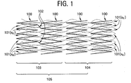
- Figure 1 shows a plurality of adjacent intraluminal stent segments 100 axially connected by a network of fibres 101 (x n ) where "x n " represents the number of fibres present, ranging from 1 to about 1 ⁇ 10 9 .
- Each adjacent segment 100 is preferably self-expanding, but may also be balloon-expandable.
- Adjacent segments may be axially connected by integral bridging elements 102 as in the group of segments 103, may be axially independent as in the group of segments 104, or may be a combination of both as in the group of segments 105.
- Fibres 101 axially connect at least two adjacent segments 100.
- a preferred exemplary embodiment is a self-expanding intraluminal segment 100 made from a superelastic alloy such as a nickel-titanium based alloy (nitinol) comprising from about 50.0 weight percent Ni to about 60 weight percent Ni, with the remainder being Ti.
- a superelastic alloy such as a nickel-titanium based alloy (nitinol) comprising from about 50.0 weight percent Ni to about 60 weight percent Ni, with the remainder being Ti.
- each intraluminal segment 100 is designed such that it is superelastic at body temperature, having an austenitic finish temperature in the range from about 22°C to about 37°C.
- Fibres 101 (x n ) are most preferably polymers, silk, collagen, or bioabsorbable compositions.
- fibres 101 (x n ) may be of one, or more than one material composition, including embodiments where single fibres 101 (x n ), or groups of fibres 101 (x n ) are composed of differing materials relative to the other fibres 101 (x n ) forming an interwoven network.
- Fibres 101 (x n ) may be oriented randomly, or in a regular pattern, such that the fibres 101 (x n ) preferably allow the intraluminal segments 100 to move relative to one another while axially connected through the network of fibres 101 (x n ).
- One preferable means for allowing relative movement is illustrated in Figure 7 , where fibres 701 (x n ) are looped over one another while being passed over and under the struts forming the individual intraluminal segments 700.
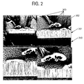
- Figure 2 illustrates a preferred embodiment of a textured surface designed to optimise the adhesion of polymer fibres to a metallic radially expandable intraluminal implant.
- This highly magnified view illustrates a metallic coating 201 with a textured surface 202 deposited on a substrate 200.
- the textured surface 202 provides increased surface area to improve bonding of polymeric fibres 203.
- the metallic coating 201 provides a biocompatible surface and is securely bound to the base metallic structure 200 using a physical vapour deposition process.
- metallic coating 201 is tantalum and the substrate 200 is a radially expandable metallic nitinol segment. Tantalum has the benefits of enhancing radiopacity, as well a preserving biocompatibility of the device.
- the polymer fibres 203 are joined to metallic surface 202 with the aid of a solvent which allows at least some of the dissolved polymer to form an interface between the textured surface and fibre.
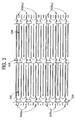
- Figure 3 and Figure 4 illustrate a plurality of intraluminal segments 300 connected by a plurality of fibres 302 (x n ), where "x n " represents the number of fibres present, ranging from 1 to about 1 ⁇ 10 9 .
- the intraluminal segments 300, and fibres 302 (x n ) are substantially as described in Figure 1 , where intraluminal segment 300 has at least one additional geometric feature 305 preferably located at the apex of an individual strut pair comprising the intraluminal segment 300 structure.
- the geometric feature 305 serves as an attachment point between fibres 302 (x n ) and intraluminal segments 300.
- the geometric feature 305 or notched tab may further serve to provide a means for transmitting axially compressive loads between intraluminal segments 300 during deployment within the target lumen.
- the geometric feature 305 may comprise a material that is more radiopaque than the remaining portions of the structure, thereby serving as a marker for accurate deployment of the device.
- one preferred means for attaching the fibre 302 (x n ) to the geometric feature 305 of the intraluminal segment 300 is to create a knotted loop 304.
- the fibres 302 (x n ) that form a network connecting intraluminal segments 300 may be of a single material composition such as those mentioned as being preferable in Figure 1 , or may be of more than one preferable material.
- Figure 5a and Figure 5b are schematic representations of the exemplary embodiment illustrated in Figure 3 and Figure 4 and described herein.
- Figure 4a shows a plurality of intraluminal segments 300, having geometric features 305 and connected fibres 302 (x n ) that are radially compressed in a manner generally consistent with being constrained within a catheter.
- Figure 5b shows the same plurality of intraluminal segments 300, geometric features 305, and connected fibres 302 (x n ) and 304 as in Figure 5a , however, the intraluminal segments 300 are in the fully-expanded state.
- intraluminal segments 100 connected by a network of fibres 101 (x n ) as shown in Figure 1 , or a network of fibres 302 (x n ) as shown in Figure 3 through Figure 5b are a means for delivering therapeutic agents to the patient.
- a detailed description of exemplary agents is included herein.
- the fibres 301 (x n ) or 302 (x n ) may either be the exclusive means of delivery, or may provide surface area in addition to that of the intraluminal segments 100, 300.
- Fibres 101 (x n ) or 302 (x n ) are most preferably impregnated with therapeutic agents, or combinations of therapeutic agents, such as those that inhibit the formation of thrombus, or the reoccurrence of stenosis.
- the fibres 101 (x n ) or 302 (x n ) that form a network connecting intraluminal segments 100, 300 may be of a single material composition such as those mentioned as being preferable in Figure 1 , or may be of more than one preferable material thereby creating a blended fibre.
- Figure 6 illustrates the detail of a geometric feature 606 similar to the feature 305 shown in Figure 3 and Figure 4 .
- the geometric feature 606 is substantially similar to that of 305 in that it serves as an anchoring point for a fibre 607, or fibres 607, as well as providing a means for transmitting axially compressive forces between intraluminal segments 600 during deployment to the target lumen.
- the fibre 607 is passed through the eyelet preferably formed by the geometric feature 606, where the fibre 607 terminates in a manner, such as a knot that preferably restrains the terminus of the fibre 607 from falling out of the geometric feature 606.
- the means by which fibres 607 are secured to the plurality of intraluminal segments 600 may either be through knotting the fibre 607 at its termination points on the first (proximal) and last (distal) intraluminal segments 600, or at intervals between intraluminal segments 600 along the length of the fibre 607.
- the geometric feature 606 is preferably located at the apex formed by adjacent struts comprising intraluminal segment 600, where there is preferably at least one feature 606 on each intraluminal segment 600 present.
- the fibres 607 that form a network connecting intraluminal segments 600 may be of a single material composition such as those mentioned as being preferable in Figure 1 , or may be of more than one preferable material.
- the number of fibres 607 present may range from 1 to about 1 x 10 9 .
- the fibres 607 may either be the exclusive means, or may provide surface area in addition to that of the intraluminal segments 600, for the delivery of therapeutic agents.
- Fibres 607 are most preferably impregnated with therapeutic agents, or combinations of therapeutic agents, such as those that inhibit the formation of thrombus, or the reoccurrence of stenosis.
- the fibres may incorporate any suitable biocompatible materials that may be non-absorbable or absorbable depending upon the application.
- the stent segments, the fibres or both may be used to deliver therapeutic and pharmaceutic agents including: anti-proliferative/antimitotic agents including natural products such as vinca alkaloids (i.e. vinblastine, vincristine, and vinorelbine), paclitaxel, epidipodophyllotoxins (i.e.
- antibiotics dactinomycin (actinomycin D) daunorubicin, doxorubicin and idarubicin
- anthracyclines mitoxantrone, bleomycins, plicamycin (mithramycin) and mitomycin
- enzymes L-asparaginase which systemically metabolises L-asparagine and deprives cells which do not have the capacity to synthesise their own asparagines
- antiplatelet agents such as G(GP) 11b/111a inhibitors and vitronectin receptor antagonists
- anti-proliferative/antimitotic alkylating agents such as nitrogen mustards (mechlorethamine, cyclophosphamide and analogs, melphalan, chlorambucil), ethylenimines and methylmelamines (hexamethylmelamine and thiotepa), alkyl sulfonates-busulfan, ni
- anti-coagulants heparin, synthetic heparin salts and other inhibitors of thrombin
- fibrinolytic agents such as tissue plasminogen activator, streptokinase and urokinase), aspirin, dipyridamole, ticlopidine, clopidogrel, abciximab; antimigratory; antisecretory (breveldin); anti-inflammatory; such as adrenocortical steroids (cortisol, cortisone, fludrocortisone, prednisone, prednisolone, 6 -methylprednisolone, triamcinolone, betamethasone, and dexamethasone), non-steroidal agents (salicylic acid derivatives i.e.
- the stents described herein may be used as therapeutic agent or drug delivery devices.
- the metallic stents may be coated with a biostable or bioabsorbable polymer or combinations thereof with the therapeutic agents incorporated therein.
- Typical material properties for coatings include flexibility, ductility, tackiness, durability, adhesion and cohesion.
- Biostable and bioabsorbable polymers that exhibit these desired properties include methacrylates, polyurethanes, silicones, polyvinylacetates, polyvinyalcohol, ethylenevinylalcohol, polyvinylidene fluoride, poly-lactic acid, poly-glycolic acid, polycaprolactone, polytrimethylene carbonate, polydioxanone, polyorthoester, polyanhydrides, polyphosphoester, polyaminoacids as well as their copolymers and blends thereof.
- the coatings may also include other additives such as radiopaque constituents, chemical stabilisers for both the coating and/or the therapeutic agent, radioactive agents, tracing agents such as radioisotopes such as tritium (i.e. heavy water) and ferromagnetic particles, and mechanical modifiers such as ceramic microspheres.
- radiopaque constituents such as radiopaque constituents, chemical stabilisers for both the coating and/or the therapeutic agent, radioactive agents, tracing agents such as radioisotopes such as tritium (i.e. heavy water) and ferromagnetic particles, and mechanical modifiers such as ceramic microspheres.
- entrapped gaps may be created between the surface of the device and the coating and/or within the coating itself. Examples of these gaps include air as well as other gases and the absence of matter (i.e. vacuum environment). These entrapped gaps may be created utilising any number of known techniques such as the injection of microencapsulated gaseous matter.
- the fibre elements are formed using a continuous fibre spinning process.
- polymer is dissolved with solvent in a highly viscous solution.
- the solution is dispensed through a nozzle or spinneret to form a polymer fibre.
- This fibre is collected by a spinning mandrel on which the stent segments are positioned. The mandrel rotates and indexes back and forth axially to cover the stent segments with polymer fibre.
- the polymer fibre contacts the surface of the stent segments, it preferentially still contains enough solvent to allow for adequate solvent bonding of the fibres to each other and the surface of the metallic substrate.
- This process provides fibres typically in the 10 ⁇ m to 100 ⁇ m diameter range.
- the fibre elements are formed using an electrospinning process.
- electrospinning processes can involve dissolving the polymer in a solvent, dispensing it from a spinneret and directing it toward a target.
- a high voltage potential between the spinneret and target in the range of 1 kV to 50 kV, creates electrostatic forces that attract the solution toward the target.
- the stream of polymer in solution is transformed to a fine fibre as most of the solvent evaporates.
- the target is typically a rotating metallic mandrel that is either grounded or charged. Stent segments are positioned on this rotating mandrel and covered with polymer fibres using this electrostatic forming process.
- the mandrel may rotate at various speeds, and also index back and forth axially or spin around a carousel to achieve preferential alignment of the fibres in the axial or circumferential directions.
- This electrostatic spinning process typically produces fibres in a range less than about 1 ⁇ m in diameter.
- the density of the fibres may be allowed to vary from a relatively sparse network to a relatively dense network. As density increases, the device approaches the configuration of a stent graft, and may provide a barrier to flow or fluid penetration. Such an implementation with a dense mesh of biostable fibres approaches the form and function of a stent graft. However, with a dense mesh of bioabsorbable or dissolving fibres provides the functionality of a temporary stent graft; such a device may have utility in a variety of clinical circumstances, including acute repair of a vascular perforation.
- the fibres are arranged in a relatively sparse network, such that the fibres to do not provide a complete barrier to flow or fluid penetration. Such a sparse architecture is especially preferred in cases where the implanted device crosses branch vessels where it is desirable to maintain patency of such branch vessels.
Landscapes
- Health & Medical Sciences (AREA)
- Engineering & Computer Science (AREA)
- Biomedical Technology (AREA)
- Heart & Thoracic Surgery (AREA)
- Life Sciences & Earth Sciences (AREA)
- Cardiology (AREA)
- Oral & Maxillofacial Surgery (AREA)
- Transplantation (AREA)
- Physics & Mathematics (AREA)
- Vascular Medicine (AREA)
- Optics & Photonics (AREA)
- Animal Behavior & Ethology (AREA)
- General Health & Medical Sciences (AREA)
- Public Health (AREA)
- Veterinary Medicine (AREA)
- Media Introduction/Drainage Providing Device (AREA)
- Prostheses (AREA)
Applications Claiming Priority (1)
| Application Number | Priority Date | Filing Date | Title |
|---|---|---|---|
| US11/755,171 US8133268B2 (en) | 2007-05-30 | 2007-05-30 | Stent/fiber structural combinations |
Publications (1)
| Publication Number | Publication Date |
|---|---|
| EP1997459A1 true EP1997459A1 (de) | 2008-12-03 |
Family
ID=39769534
Family Applications (1)
| Application Number | Title | Priority Date | Filing Date |
|---|---|---|---|
| EP08251858A Withdrawn EP1997459A1 (de) | 2007-05-30 | 2008-05-28 | Strukturelle Stent-/Faserkombinationen |
Country Status (4)
| Country | Link |
|---|---|
| US (2) | US8133268B2 (de) |
| EP (1) | EP1997459A1 (de) |
| JP (2) | JP5191802B2 (de) |
| CA (1) | CA2632391C (de) |
Cited By (7)
| Publication number | Priority date | Publication date | Assignee | Title |
|---|---|---|---|---|
| EP2226084A1 (de) * | 2007-03-28 | 2010-09-08 | Medinol. LTD. | Hybridstent mit einem Faser- oder Drahtgerüst |
| CN102293688A (zh) * | 2011-06-03 | 2011-12-28 | 浙江星月生物科技股份有限公司 | 一种蚕丝支架及其制备与应用 |
| GB2488165A (en) * | 2011-02-18 | 2012-08-22 | Cook Medical Technologies Llc | Stents with flat or concave apexes to prevent interdigitation |
| US8382821B2 (en) | 1998-12-03 | 2013-02-26 | Medinol Ltd. | Helical hybrid stent |
| CN103585674A (zh) * | 2013-11-06 | 2014-02-19 | 华侨大学 | 一种丝素蛋白多孔纤维支架的制备方法 |
| US9039755B2 (en) | 2003-06-27 | 2015-05-26 | Medinol Ltd. | Helical hybrid stent |
| US9155639B2 (en) | 2009-04-22 | 2015-10-13 | Medinol Ltd. | Helical hybrid stent |
Families Citing this family (19)
| Publication number | Priority date | Publication date | Assignee | Title |
|---|---|---|---|---|
| SG175723A1 (en) | 2004-05-25 | 2011-12-29 | Tyco Healthcare | Vascular stenting for aneurysms |
| WO2005115118A2 (en) | 2004-05-25 | 2005-12-08 | Chestnut Medical Technologies, Inc. | Flexible vascular occluding device |
| US8623067B2 (en) | 2004-05-25 | 2014-01-07 | Covidien Lp | Methods and apparatus for luminal stenting |
| WO2007100556A1 (en) | 2006-02-22 | 2007-09-07 | Ev3 Inc. | Embolic protection systems having radiopaque filter mesh |
| CN102149859B (zh) | 2009-06-25 | 2015-08-26 | 北京阿迈特医疗器械有限公司 | 用于制备三维多孔管状支架的方法及设备 |
| DE102009059901A1 (de) * | 2009-12-21 | 2011-06-22 | Julius-Maximilians-Universität Würzburg, 97070 | Kollagenfaserkonstrukte für den Kreuzbandersatz |
| US10092426B2 (en) * | 2011-05-31 | 2018-10-09 | Cook Medical Technologies Llc | Non-foreshortening, axial tension constrainable stent |
| US20130085564A1 (en) * | 2011-10-03 | 2013-04-04 | Abbott Cardiovascular Systems Inc. | Modified scaffolds for peripheral applications |
| US10582998B1 (en) * | 2012-10-17 | 2020-03-10 | Medshape, Inc. | Shape memory polymer fabrics |
| US9114001B2 (en) | 2012-10-30 | 2015-08-25 | Covidien Lp | Systems for attaining a predetermined porosity of a vascular device |
| US9452070B2 (en) * | 2012-10-31 | 2016-09-27 | Covidien Lp | Methods and systems for increasing a density of a region of a vascular device |
| US9943427B2 (en) | 2012-11-06 | 2018-04-17 | Covidien Lp | Shaped occluding devices and methods of using the same |
| US9157174B2 (en) | 2013-02-05 | 2015-10-13 | Covidien Lp | Vascular device for aneurysm treatment and providing blood flow into a perforator vessel |
| AU2014269936B2 (en) | 2013-05-23 | 2018-04-26 | S.T.S. Medical Ltd. | Shape change structure |
| US10912663B2 (en) | 2014-11-26 | 2021-02-09 | S.T.S. Medical Ltd. | Shape change structure for treatment of nasal conditions including sinusitis |
| CN105030391B (zh) * | 2015-07-07 | 2018-07-20 | 南昌大学 | 一种具有表面织构的血管支架 |
| US9861410B2 (en) | 2016-05-06 | 2018-01-09 | Medos International Sarl | Methods, devices, and systems for blood flow |
| CN113040988B (zh) * | 2019-12-26 | 2023-06-16 | 先健科技(深圳)有限公司 | 血管支架 |
| CA3260105A1 (en) * | 2022-06-24 | 2023-12-28 | Razmodics Llc | ESTABLISHABLE SCAFFOLDINGS HAVING BIODEGRADABLE COMPONENTS AND THEIR MANUFACTURE AND USE PROCESSES |
Citations (6)
| Publication number | Priority date | Publication date | Assignee | Title |
|---|---|---|---|---|
| WO2000042947A2 (en) * | 1999-01-22 | 2000-07-27 | Gore Enterprise Holdings, Inc. | Covered endoprosthesis and delivery system |
| US20030208260A1 (en) * | 1994-09-08 | 2003-11-06 | Lilip Lau | Procedures for introducing stents and stent-grafts |
| WO2006083991A2 (en) * | 2005-02-04 | 2006-08-10 | Poly-Med, Inc. | Fiber-reinforced composite absorbable endoureteral stent |
| WO2006099450A2 (en) * | 2005-03-14 | 2006-09-21 | Abbott Laboratories | Crack/fatigue resistant endoprosthesis |
| WO2006127825A1 (en) * | 2005-05-23 | 2006-11-30 | Incept Llc | Apparatus and methods for locating an ostium of a vessel |
| EP1834606A1 (de) * | 2006-03-16 | 2007-09-19 | Sorin Biomedica Cardio S.R.L. | Stents |
Family Cites Families (21)
| Publication number | Priority date | Publication date | Assignee | Title |
|---|---|---|---|---|
| US4792336A (en) * | 1986-03-03 | 1988-12-20 | American Cyanamid Company | Flat braided ligament or tendon implant device having texturized yarns |
| US5147400A (en) * | 1989-05-10 | 1992-09-15 | United States Surgical Corporation | Connective tissue prosthesis |
| US5500013A (en) * | 1991-10-04 | 1996-03-19 | Scimed Life Systems, Inc. | Biodegradable drug delivery vascular stent |
| JP2961287B2 (ja) * | 1991-10-18 | 1999-10-12 | グンゼ株式会社 | 生体管路拡張具、その製造方法およびステント |
| US6165210A (en) * | 1994-04-01 | 2000-12-26 | Gore Enterprise Holdings, Inc. | Self-expandable helical intravascular stent and stent-graft |
| JP3129327B2 (ja) * | 1994-04-01 | 2001-01-29 | プログラフト メディカル,インコーポレイテッド | 自己拡張可能なステントおよびステント−グラフトならびにそれらの使用方法 |
| US6193745B1 (en) * | 1995-10-03 | 2001-02-27 | Medtronic, Inc. | Modular intraluminal prosteheses construction and methods |
| US5824040A (en) * | 1995-12-01 | 1998-10-20 | Medtronic, Inc. | Endoluminal prostheses and therapies for highly variable body lumens |
| WO1997033532A2 (en) * | 1996-03-13 | 1997-09-18 | Medtronic, Inc. | Endoluminal prostheses and therapies for multiple-branch body lumen systems |
| DE19703482A1 (de) * | 1997-01-31 | 1998-08-06 | Ernst Peter Prof Dr M Strecker | Stent |
| US6565599B1 (en) * | 2000-12-28 | 2003-05-20 | Advanced Cardiovascular Systems, Inc. | Hybrid stent |
| JP2002291904A (ja) * | 2001-03-30 | 2002-10-08 | Shimadzu Corp | 生体吸収性ステント及びその製造方法 |
| US20030153972A1 (en) * | 2002-02-14 | 2003-08-14 | Michael Helmus | Biodegradable implantable or insertable medical devices with controlled change of physical properties leading to biomechanical compatibility |
| GB0206061D0 (en) * | 2002-03-14 | 2002-04-24 | Angiomed Ag | Metal structure compatible with MRI imaging, and method of manufacturing such a structure |
| AU2003300022A1 (en) * | 2002-12-30 | 2004-07-29 | Angiotech International Ag | Silk-containing stent graft |
| US20050085894A1 (en) * | 2003-10-16 | 2005-04-21 | Kershner James R. | High strength and lubricious materials for vascular grafts |
| EP1715826B1 (de) * | 2004-02-02 | 2013-03-06 | Conceptus, Inc. | Verbesserung des einwachsens von gewebe zur kontrazeption |
| FR2872083A1 (fr) | 2004-06-23 | 2005-12-30 | Peguform France Sa | Procede de fabrication d'une piece de vehicule entre un poincon et une matrice |
| CN1745677A (zh) | 2004-08-06 | 2006-03-15 | 邓通讯 | 按需自动送鞋鞋柜 |
| US7323008B2 (en) * | 2004-08-09 | 2008-01-29 | Medtronic Vascular, Inc. | Flexible stent |
| KR20070046917A (ko) | 2004-08-12 | 2007-05-03 | 글락소스미쓰클라인 이스트라지바치키 센타 자그레브 디.오.오. | 위장관의 염증성 질환의 치료를 위한 세포-특이적컨쥬게이트의 용도 |
-
2007
- 2007-05-30 US US11/755,171 patent/US8133268B2/en not_active Expired - Fee Related
-
2008
- 2008-05-28 EP EP08251858A patent/EP1997459A1/de not_active Withdrawn
- 2008-05-28 CA CA2632391A patent/CA2632391C/en active Active
- 2008-05-29 JP JP2008140447A patent/JP5191802B2/ja not_active Expired - Fee Related
-
2012
- 2012-02-06 US US13/367,142 patent/US8439967B2/en not_active Expired - Fee Related
- 2012-12-21 JP JP2012279248A patent/JP5615893B2/ja not_active Expired - Fee Related
Patent Citations (6)
| Publication number | Priority date | Publication date | Assignee | Title |
|---|---|---|---|---|
| US20030208260A1 (en) * | 1994-09-08 | 2003-11-06 | Lilip Lau | Procedures for introducing stents and stent-grafts |
| WO2000042947A2 (en) * | 1999-01-22 | 2000-07-27 | Gore Enterprise Holdings, Inc. | Covered endoprosthesis and delivery system |
| WO2006083991A2 (en) * | 2005-02-04 | 2006-08-10 | Poly-Med, Inc. | Fiber-reinforced composite absorbable endoureteral stent |
| WO2006099450A2 (en) * | 2005-03-14 | 2006-09-21 | Abbott Laboratories | Crack/fatigue resistant endoprosthesis |
| WO2006127825A1 (en) * | 2005-05-23 | 2006-11-30 | Incept Llc | Apparatus and methods for locating an ostium of a vessel |
| EP1834606A1 (de) * | 2006-03-16 | 2007-09-19 | Sorin Biomedica Cardio S.R.L. | Stents |
Cited By (11)
| Publication number | Priority date | Publication date | Assignee | Title |
|---|---|---|---|---|
| US8382821B2 (en) | 1998-12-03 | 2013-02-26 | Medinol Ltd. | Helical hybrid stent |
| US9039755B2 (en) | 2003-06-27 | 2015-05-26 | Medinol Ltd. | Helical hybrid stent |
| US9456910B2 (en) | 2003-06-27 | 2016-10-04 | Medinol Ltd. | Helical hybrid stent |
| US10363152B2 (en) | 2003-06-27 | 2019-07-30 | Medinol Ltd. | Helical hybrid stent |
| EP2226084A1 (de) * | 2007-03-28 | 2010-09-08 | Medinol. LTD. | Hybridstent mit einem Faser- oder Drahtgerüst |
| US9155639B2 (en) | 2009-04-22 | 2015-10-13 | Medinol Ltd. | Helical hybrid stent |
| GB2488165A (en) * | 2011-02-18 | 2012-08-22 | Cook Medical Technologies Llc | Stents with flat or concave apexes to prevent interdigitation |
| GB2488165B (en) * | 2011-02-18 | 2013-08-07 | Cook Medical Technologies Llc | Prosthesis and method of manufacturing the same |
| CN102293688A (zh) * | 2011-06-03 | 2011-12-28 | 浙江星月生物科技股份有限公司 | 一种蚕丝支架及其制备与应用 |
| CN102293688B (zh) * | 2011-06-03 | 2013-09-04 | 浙江星月生物科技股份有限公司 | 一种蚕丝支架及其制备与应用 |
| CN103585674A (zh) * | 2013-11-06 | 2014-02-19 | 华侨大学 | 一种丝素蛋白多孔纤维支架的制备方法 |
Also Published As
| Publication number | Publication date |
|---|---|
| JP2013052306A (ja) | 2013-03-21 |
| JP5191802B2 (ja) | 2013-05-08 |
| JP5615893B2 (ja) | 2014-10-29 |
| US20120179240A1 (en) | 2012-07-12 |
| US20080300668A1 (en) | 2008-12-04 |
| US8439967B2 (en) | 2013-05-14 |
| US8133268B2 (en) | 2012-03-13 |
| JP2009028514A (ja) | 2009-02-12 |
| CA2632391A1 (en) | 2008-11-30 |
| CA2632391C (en) | 2014-11-18 |
Similar Documents
| Publication | Publication Date | Title |
|---|---|---|
| US8439967B2 (en) | Stent/fiber structural combinations | |
| JP6130392B2 (ja) | 医療装置を送達するためのシステム及び方法 | |
| US8778011B2 (en) | Soft crowns | |
| CN104768476B (zh) | 用于心耳的封堵器 | |
| US20090105747A1 (en) | Vena Cava Filter with Stent | |
| US10206797B2 (en) | Helical high fatigue stent-graft | |
| US20100324657A1 (en) | Locked segments pushable stent-graft | |
| JP2009519731A (ja) | フィラメントを有する大静脈フィルタ | |
| JP2013059643A (ja) | 放射線不透過性ビーディングを有する移植片及びステント植皮 | |
| US20110118819A1 (en) | Method of manufacturing a polymeric stent with a hybrid support structure | |
| US9839541B2 (en) | Reconstrainable stent system | |
| JP6898467B2 (ja) | 管腔内デバイス | |
| US20170360552A1 (en) | Expandable Stent with Constrained End | |
| WO2025064501A1 (en) | Left atrial appendage closure device with drug-eluting composition |
Legal Events
| Date | Code | Title | Description |
|---|---|---|---|
| PUAI | Public reference made under article 153(3) epc to a published international application that has entered the european phase |
Free format text: ORIGINAL CODE: 0009012 |
|
| AK | Designated contracting states |
Kind code of ref document: A1 Designated state(s): AT BE BG CH CY CZ DE DK EE ES FI FR GB GR HR HU IE IS IT LI LT LU LV MC MT NL NO PL PT RO SE SI SK TR |
|
| AX | Request for extension of the european patent |
Extension state: AL BA MK RS |
|
| 17P | Request for examination filed |
Effective date: 20081229 |
|
| 17Q | First examination report despatched |
Effective date: 20090206 |
|
| AKX | Designation fees paid |
Designated state(s): AT BE BG CH CY CZ DE DK EE ES FI FR GB GR HR HU IE IS IT LI LT LU LV MC MT NL NO PL PT RO SE SI SK TR |
|
| STAA | Information on the status of an ep patent application or granted ep patent |
Free format text: STATUS: THE APPLICATION IS DEEMED TO BE WITHDRAWN |
|
| 18D | Application deemed to be withdrawn |
Effective date: 20090806 |