EP1997421A1 - Video endoscope - Google Patents
Video endoscope Download PDFInfo
- Publication number
- EP1997421A1 EP1997421A1 EP08009839A EP08009839A EP1997421A1 EP 1997421 A1 EP1997421 A1 EP 1997421A1 EP 08009839 A EP08009839 A EP 08009839A EP 08009839 A EP08009839 A EP 08009839A EP 1997421 A1 EP1997421 A1 EP 1997421A1
- Authority
- EP
- European Patent Office
- Prior art keywords
- video endoscope
- endoscope according
- working part
- light
- working
- Prior art date
- Legal status (The legal status is an assumption and is not a legal conclusion. Google has not performed a legal analysis and makes no representation as to the accuracy of the status listed.)
- Granted
Links
- 230000005540 biological transmission Effects 0.000 claims abstract description 19
- 239000013307 optical fiber Substances 0.000 claims abstract description 12
- 230000007246 mechanism Effects 0.000 claims description 9
- 230000008901 benefit Effects 0.000 description 25
- 230000008878 coupling Effects 0.000 description 12
- 238000010168 coupling process Methods 0.000 description 12
- 238000005859 coupling reaction Methods 0.000 description 12
- 238000000034 method Methods 0.000 description 6
- 230000008569 process Effects 0.000 description 6
- 230000001954 sterilising effect Effects 0.000 description 6
- 238000003384 imaging method Methods 0.000 description 5
- 238000004659 sterilization and disinfection Methods 0.000 description 5
- 238000004519 manufacturing process Methods 0.000 description 4
- 238000001356 surgical procedure Methods 0.000 description 4
- 238000011109 contamination Methods 0.000 description 3
- 230000003287 optical effect Effects 0.000 description 3
- 230000000052 comparative effect Effects 0.000 description 2
- 238000010276 construction Methods 0.000 description 2
- 239000000835 fiber Substances 0.000 description 2
- 239000012530 fluid Substances 0.000 description 2
- 238000005286 illumination Methods 0.000 description 2
- 230000009993 protective function Effects 0.000 description 2
- TVEXGJYMHHTVKP-UHFFFAOYSA-N 6-oxabicyclo[3.2.1]oct-3-en-7-one Chemical compound C1C2C(=O)OC1C=CC2 TVEXGJYMHHTVKP-UHFFFAOYSA-N 0.000 description 1
- 208000029836 Inguinal Hernia Diseases 0.000 description 1
- 230000003187 abdominal effect Effects 0.000 description 1
- 238000005452 bending Methods 0.000 description 1
- 230000015572 biosynthetic process Effects 0.000 description 1
- 238000006243 chemical reaction Methods 0.000 description 1
- 210000000038 chest Anatomy 0.000 description 1
- 239000011248 coating agent Substances 0.000 description 1
- 238000000576 coating method Methods 0.000 description 1
- 150000001875 compounds Chemical class 0.000 description 1
- 239000004020 conductor Substances 0.000 description 1
- 230000006735 deficit Effects 0.000 description 1
- 230000000249 desinfective effect Effects 0.000 description 1
- 238000010292 electrical insulation Methods 0.000 description 1
- 238000005265 energy consumption Methods 0.000 description 1
- 238000005516 engineering process Methods 0.000 description 1
- 230000002349 favourable effect Effects 0.000 description 1
- 230000006870 function Effects 0.000 description 1
- 230000001771 impaired effect Effects 0.000 description 1
- 238000002347 injection Methods 0.000 description 1
- 239000007924 injection Substances 0.000 description 1
- 238000001746 injection moulding Methods 0.000 description 1
- 239000007788 liquid Substances 0.000 description 1
- 230000007774 longterm Effects 0.000 description 1
- 239000000463 material Substances 0.000 description 1
- 238000002324 minimally invasive surgery Methods 0.000 description 1
- 238000003032 molecular docking Methods 0.000 description 1
- 238000004382 potting Methods 0.000 description 1
- 239000000243 solution Substances 0.000 description 1
- 238000012414 sterilization procedure Methods 0.000 description 1
Images


Classifications
-
- A—HUMAN NECESSITIES
- A61—MEDICAL OR VETERINARY SCIENCE; HYGIENE
- A61B—DIAGNOSIS; SURGERY; IDENTIFICATION
- A61B1/00—Instruments for performing medical examinations of the interior of cavities or tubes of the body by visual or photographical inspection, e.g. endoscopes; Illuminating arrangements therefor
- A61B1/00142—Instruments for performing medical examinations of the interior of cavities or tubes of the body by visual or photographical inspection, e.g. endoscopes; Illuminating arrangements therefor with means for preventing contamination, e.g. by using a sanitary sheath
-
- A—HUMAN NECESSITIES
- A61—MEDICAL OR VETERINARY SCIENCE; HYGIENE
- A61B—DIAGNOSIS; SURGERY; IDENTIFICATION
- A61B1/00—Instruments for performing medical examinations of the interior of cavities or tubes of the body by visual or photographical inspection, e.g. endoscopes; Illuminating arrangements therefor
- A61B1/00064—Constructional details of the endoscope body
- A61B1/00071—Insertion part of the endoscope body
-
- A—HUMAN NECESSITIES
- A61—MEDICAL OR VETERINARY SCIENCE; HYGIENE
- A61B—DIAGNOSIS; SURGERY; IDENTIFICATION
- A61B1/00—Instruments for performing medical examinations of the interior of cavities or tubes of the body by visual or photographical inspection, e.g. endoscopes; Illuminating arrangements therefor
- A61B1/00064—Constructional details of the endoscope body
- A61B1/00103—Constructional details of the endoscope body designed for single use
-
- A—HUMAN NECESSITIES
- A61—MEDICAL OR VETERINARY SCIENCE; HYGIENE
- A61B—DIAGNOSIS; SURGERY; IDENTIFICATION
- A61B1/00—Instruments for performing medical examinations of the interior of cavities or tubes of the body by visual or photographical inspection, e.g. endoscopes; Illuminating arrangements therefor
- A61B1/00064—Constructional details of the endoscope body
- A61B1/00105—Constructional details of the endoscope body characterised by modular construction
-
- A—HUMAN NECESSITIES
- A61—MEDICAL OR VETERINARY SCIENCE; HYGIENE
- A61B—DIAGNOSIS; SURGERY; IDENTIFICATION
- A61B1/00—Instruments for performing medical examinations of the interior of cavities or tubes of the body by visual or photographical inspection, e.g. endoscopes; Illuminating arrangements therefor
- A61B1/04—Instruments for performing medical examinations of the interior of cavities or tubes of the body by visual or photographical inspection, e.g. endoscopes; Illuminating arrangements therefor combined with photographic or television appliances
- A61B1/05—Instruments for performing medical examinations of the interior of cavities or tubes of the body by visual or photographical inspection, e.g. endoscopes; Illuminating arrangements therefor combined with photographic or television appliances characterised by the image sensor, e.g. camera, being in the distal end portion
-
- A—HUMAN NECESSITIES
- A61—MEDICAL OR VETERINARY SCIENCE; HYGIENE
- A61B—DIAGNOSIS; SURGERY; IDENTIFICATION
- A61B1/00—Instruments for performing medical examinations of the interior of cavities or tubes of the body by visual or photographical inspection, e.g. endoscopes; Illuminating arrangements therefor
- A61B1/06—Instruments for performing medical examinations of the interior of cavities or tubes of the body by visual or photographical inspection, e.g. endoscopes; Illuminating arrangements therefor with illuminating arrangements
- A61B1/0607—Instruments for performing medical examinations of the interior of cavities or tubes of the body by visual or photographical inspection, e.g. endoscopes; Illuminating arrangements therefor with illuminating arrangements for annular illumination
-
- A—HUMAN NECESSITIES
- A61—MEDICAL OR VETERINARY SCIENCE; HYGIENE
- A61B—DIAGNOSIS; SURGERY; IDENTIFICATION
- A61B1/00—Instruments for performing medical examinations of the interior of cavities or tubes of the body by visual or photographical inspection, e.g. endoscopes; Illuminating arrangements therefor
- A61B1/06—Instruments for performing medical examinations of the interior of cavities or tubes of the body by visual or photographical inspection, e.g. endoscopes; Illuminating arrangements therefor with illuminating arrangements
- A61B1/07—Instruments for performing medical examinations of the interior of cavities or tubes of the body by visual or photographical inspection, e.g. endoscopes; Illuminating arrangements therefor with illuminating arrangements using light-conductive means, e.g. optical fibres
-
- A—HUMAN NECESSITIES
- A61—MEDICAL OR VETERINARY SCIENCE; HYGIENE
- A61B—DIAGNOSIS; SURGERY; IDENTIFICATION
- A61B1/00—Instruments for performing medical examinations of the interior of cavities or tubes of the body by visual or photographical inspection, e.g. endoscopes; Illuminating arrangements therefor
- A61B1/06—Instruments for performing medical examinations of the interior of cavities or tubes of the body by visual or photographical inspection, e.g. endoscopes; Illuminating arrangements therefor with illuminating arrangements
- A61B1/0661—Endoscope light sources
- A61B1/0684—Endoscope light sources using light emitting diodes [LED]
Definitions
- the invention relates to a video endoscope with a disposable working part, wherein the working part has a shaft, at the distal end of a lens and an image sensor are arranged, and wherein the working part further comprises an electrical transmission system for transmitting the image information and at least one light guide for transmitting light from proximal to distal, and with a control panel, wherein a proximal end of the working member is releasably connectable to a distal end of the control panel via an interface.
- Video endoscopes are used, for example, in minimally invasive procedures in arthroscopy, in the abdominal and thorax mirror, in inguinal hernias and in joint and spine operations.
- the endoscopes assist the surgeon in carrying out the operation by making the largest possible field of vision visible in the operating area.
- a first component of such endoscopes is an imaging system.
- the imaging system serves to receive observation light from the observation room or operating room and to transmit image information from distal to proximal.
- the imaging system may conventionally consist of an optical image transmission system having an objective in the distal end of the shaft, a lens system thereafter proximal, for example in the form of a rod lens system, or an ordered fiber bundle and a proximal eyepiece, through which the eye is viewing can be, or to which a camera can be connected.
- An electronic imaging system has imaging optics and an image capture chip in the distal end of the shaft that converts the light signals into electrical signals that are transmitted proximally via electrical leads.
- a camera module At the proximal end of a camera module is present, which is usually additionally designed as a control panel, and forwards the electronic image information to an image processing unit.
- a second component of such endoscopes is a lighting system.
- the illumination system serves to transmit light from proximal to distal in order to illuminate the observation room or examination room with light.
- a video endoscope with the aforementioned constructive features is eg from the JP 06254049 A known.
- a disposable working part solves the problem of sterilizing the video endoscope in part by connecting a pre-sterilized working part as a disposable component to a control panel
- the control panel is due to fluids and fluids present in the operating room can be contaminated and contaminated, for example can lead to faults in the control panel.
- the keypad still needs to be sterilized, although this no longer needs to be to the same high degree as when the keypad is fixedly connected to the working part that is inserted directly into the body of a patient.
- less burdensome sterilization procedures such as e.g. Inserting the control panel in a disinfecting liquid can cause long-term disruption to failure of the control panel.
- the object underlying the invention is achieved by a video endoscope of the type described above, in which a sterile sixteengeraffter hose is arranged on the working part, with which the control panel is umhüllbar.
- This measure has the advantage that the control panel, which has a plurality of sterilization-sensitive elements, is protected by the tube from contamination.
- the working part is connected to the non-sterilized control panel. Then the working part is grasped by a sterile hand of the surgeon and with the second hand the sterile tube, which is arranged on the working part, is pulled over the non-sterilized operating part, so that the tube envelops the operating part. After use, the working part is separated from the control panel and disposed of the working part with the hose. This process of wrapping can be done positively using a docking device.
- the interface is designed such that the image information can be transmitted from the image sensor to the control unit.
- This measure has the advantage that the coupling of the elements responsible for the image transmission is ensured by such an embodiment of the interface.
- the image information is transmitted by the sensor via the interface to the operating element by means of the electrical transmission system, so that the image information can be displayed as image after image processing on a monitor. This allows the surgeon to observe the endoscopic surgical field on the monitor.
- the interface is designed such that light can be transmitted from the operating part to the working part.
- This measure has the advantage that light is passed from the control panel to the distal end of the working part, whereby the examination room is illuminated with light.
- the working part on an outer part, which is designed as a shaft.
- This measure has the advantage that the shaft fulfills a protective function, since the elements located in the shaft, such as sensor, transmission system, etc., are protected against impairment, for example, by attacking bending forces.
- This shaft can be formed as a plastic shaft and executed as an injection molded part. He is thus extremely inexpensive to implement.
- the at least one light guide is arranged in the shaft.
- the shaft likewise protects the optical waveguide.
- the shaft can be formed of a light-conducting plastic. This contributes to a simple and inexpensive construction of the working part.
- the working part has an inner part, in which the image sensor and the electrical transmission system are arranged.
- This measure has the advantage that such a configuration of the working part prevents damage to the image sensor and the image transmission system, since the elements are enclosed by the inner part and thus protected.
- the outer part is rotatable relative to the inner part.
- This measure has the advantage that the so-called image erection is ensured by rotation of the outer part with the lens relative to the image sensor.
- Image erection is understood to mean a certain horizontal alignment of the monitor image generated by the camera module after rotation of the endoscope, usually with an asymmetrical viewing direction (for example 30 °) about the shaft axis.
- Some surgeons want a consistent horizontal alignment of the surgical image seen on the monitor when the endoscope is rotated from a home position during surgery. For this purpose, it has become known, nachzucard the image pickup unit accordingly, thereby erecting the image again.
- a mechanism for rotating the outer part is provided.
- This measure has the advantage that the erection of the image can be performed simply by operating the mechanism, even with one hand by the surgeon during the surgical procedure.
- the mechanism can be manually, for example.
- an operating lever or motor-driven for the drive of the motor rotation of the outer part, the working part, for example, a friction area or a toothing and the control unit having a drive roller or a gear.
- the manual and motor driven mechanism are structurally easy to implement.
- the image sensor is designed as a CMOS sensor.
- CMOS technology has a much lower energy consumption compared to the CCD sensors and allows for a larger production volume a favorable production, since they can be manufactured without conversion to the designed for high volume production lines and thus cause a low production cost per chip.
- the disposable working part can be produced particularly inexpensively.
- the image sensor is designed as a CCD sensor.
- This measure has the advantage that the CCD sensors are usually more sensitive to light than conventional CMOS sensors.
- the electrical transmission system is designed as at least one continuous board.
- This measure has the advantage that a continuous board is a structurally simple and at the same time cost-effective design. Furthermore, in such a configuration of the transmission system no additional cable connections and contacts are necessary. This contributes to a simple and easy-to-assemble construction of the working part.
- a proximal end of the board is designed as a plug.
- This measure has the advantage that the image information from the image sensor, which is arranged in the working part, is transmitted to the operating part through the plug. Furthermore, such an embodiment of the working part has the advantage that the cost-effective board is designed to be multifunctional, so that no additional component has to be used. This contributes to a lower assembly costs.
- the image sensor and the circuit board are enclosed by a cylindrical element.
- This measure has the advantage that the entire arrangement consisting of the image sensor and the board is stabilized or reinforced by the cylindrical element.
- the cylindrical element also advantageously serves to insulate the conductor wires.
- the working part has at least one channel.
- the at least one channel e.g. can be used to rinse and clean the lens or for supplying a medical instrument.
- the channel preferably opens out laterally from the shaft, in front of the coupling region with the control panel.
- the proximal end of the working part has a larger diameter than the distal end.
- This measure has the advantage that the distal end region of the working part has enough space for the electrical plug system and the coaxially arranged light coupling through such a configuration.
- LEDs are arranged in the working part.
- This measure has the advantage that the LEDs, which can be supplied with electrical power via the plug, couple light into the outer part.
- LEDs are arranged in the inner part of the working part.
- This measure has the advantage that light can be coupled radially into the outer part by the LEDs, which is deflected there by mirror elements to the distal part.
- a light entrance is arranged at the proximal end of the working part.
- This measure in turn has the advantage that light can be transmitted from the control panel via the light entrance to the working part, so that the operating area is illuminated.
- a light exit is arranged at the distal end of the control panel.
- This measure has the advantage that light can be transmitted from the operating part to the working part by the light exit.
- the light exit of the operating part is designed such that, after the operating part is connected to the working part, it is in direct contact with the light entry of the working part.
- the light emission has either LEDs or optical fibers.
- a socket for receiving the plug is arranged at the distal end of the control panel.
- This measure has the advantage that in a structurally simple way an electrical coupling between the working part and control panel is created.
- control panel on controls.
- This measure has the advantage that the surgeon can operate the camera or other switches or valves by simply operating the controls arranged on the control panel.
- LEDs are peripherally arranged in the distal region of the operating part, which illuminate the light entry of the working part.
- This measure has the advantage that circumferentially evenly distributed light can be coupled and that this is guaranteed even with an existing rotation in each rotational position.
- circumferentially distributed light fibers are arranged in the distal region of the operating part, which illuminate the light entry of the working part.
- This measure has the same advantage as mentioned above, wherein the light is guided to the distal region of the operating part by optical fibers.
- circumferentially distributed LEDs are arranged in the operating part, which couple light radially into the working part, which can be deflected distally via mirror elements.
- This type of coupling can also be present in the working part itself, for example, when the working part and the operating part are not rotatably coupled to each other and the working part has an inner part and a rotatable outer part.
- FIG. 1 to 7 represented video endoscope is provided in its entirety by the reference numeral 10.
- the video endoscope 10 has a working part 12 and an operating part 14, which are detachably connectable to one another via an interface 16, as will be described in more detail later.
- the working part 12 is designed as a disposable instrument and the operating part 14 is designed as a reusable instrument.
- the working part 12 has an outer part 18, which is designed as a shaft 20 in this embodiment.
- the shaft 20 has at least one light guide 26 which conducts light from proximal to distal.
- the shaft 20 is formed of a photoconductive plastic.
- a collapsed tube 27 is arranged, the exact operation of which will be described below with reference to FIG Fig. 6 and 7 will be explained in more detail.
- the shaft 20 is hermetically sealed at its distal end 22 with an objective 24, as shown in particular in the enlarged view in FIG Fig. 3 is apparent.
- the shaft 20 formed of a light-conducting plastic is produced in an injection molding process. At the same time a part of the lens 24 can be injected with it.
- the working part 12 also has an inner part 30, which in particular from the illustration in Fig. 3 is apparent.
- an image sensor 32 is received, which is formed in this embodiment as a CMOS sensor.
- the sensor 32 converts the light signals into electrical signals.
- an electrical transmission system 34 is arranged, which transmits the image signals from the sensor 32 to the proximal.
- the electrical transmission system 34 is formed as a continuous board 36.
- a distal end of the board 36 is formed as a plug 38, which in particular from the enlarged view in FIG Fig. 2 is apparent.
- the function of the plug 38 will be described later.
- the image sensor 32 and the electrical transmission system 34 formed as a circuit board 36 are enclosed by a cylindrical element 40. That from a potting compound formed cylindrical member 40 serves to stabilize the image sensor 32 and the circuit board 36 and for electrical insulation.
- the outer part 18 is rotatable relative to the inner part 30.
- the rotatability of the lens 24 arranged at the distal end of the shaft 20 with respect to the image sensor 32 arranged in the inner part 30 enables image formation.
- a mechanism 42 for rotating the outer member 18 is provided.
- the mechanism 42 can be driven manually or by motor.
- an actuating lever 44 is provided, which is arranged on the proximal side of the working part 12. By manually rotating the operating lever 44, the outer part 18 of the working part 12 is rotated with respect to the inner part 30.
- the working part 12 has a toothing or a friction region 46 which is arranged at the proximal end 48 of the working part 12.
- the operating part 14 has at its distal end 64 a toothed wheel or a friction wheel 72 which, after the two elements 12 and 14 are connected, interacts with the toothing or friction region 46 of the working part 12.
- a locking element 50 is arranged, which serves for locking the working part 12 on the control unit 14.
- the locking element 50 is formed as a bolt 52.
- annular light inlet 54 is further arranged, by means of which light is transmitted from the operating part 14 to the working part 12.
- the area 56 in this case represents the area at which the tube 27, not shown here, is connected to the working part 12.
- the control panel 14 is designed as a handle 60, as that particular from Fig. 4 evident.
- the handle 60 is connected to a cable 62.
- the control unit 14 contains sterilization-sensitive electronic elements, which are not shown here.
- the operating part 14 has at its distal end 64 a slot 68 having a socket 66, in which the plug 38 of the board 36 is inserted.
- an electrical coupling is provided which enables the transmission of the image information from the image sensor 32 to the control unit 14.
- the transmitted image information is visible after image processing for the surgeon as an image on a monitor.
- a recess 70 is provided at the distal end 64 of the operating part 14, in which the locking element 50 formed as a bolt 52 of the working part 12 can be inserted, whereby the working part 12 is connected to the control unit 14. Such a situation is in Fig. 5 shown.
- a light outlet 74 is also arranged, which is annular in this embodiment.
- 72 LEDs 75 are arranged on the light exit.
- the light exit 72 of the operating part 14 is arranged and configured such that it is in contact with the light entrance 54 of the working part 12 after the working part 12 has been connected to the operating part 14. As a result, light is transmitted from the operating part 14 to the working part 12.
- control elements 76, 77, 78, 79 are arranged, by means of which the camera is actuated.
- a further embodiment of a working part 80 is shown, which also has a shaft 82.
- the working part 80 has the same elements as that in FIG Fig. 1 to 5 shown working part 12. The corresponding elements are provided with the same reference numerals as in the working part 12.
- FIG. 6 shown working part 80 differs from the working part 12 in that it has a laterally emerging instrument channel 84, via which an instrument is inserted.
- a hose can be connected to the end.
- the instrument channel 84 exits in front of the area where the components are put together.
- the working part 80 is removed with the sterile tube 58 from a sterile coating (not shown here) and connected to the non-sterilized operating part 14. Then the sterile tube 58 fixed to the working part 80 is pulled over the operating part 14 designed as a handle 60, so that the non-sterilized operating part 14 is enveloped by the sterile tube 58. Such a situation is in Fig. 7 shown.
- the working part 80 is separated with the sterile tube 27 of the control panel 14 and disposed of.
- a working part 92 is shown, which is coupled via a plug 94 with a control panel 96.
- circumferentially distributed optical fibers 93 which extend from the proximal to the distal end of the working part 92.
- a variant of the light coupling is shown in the working part, namely by corresponding circumferentially arranged LEDs 98.
- another possibility is shown, namely by corresponding circumferentially distributed optical fibers 100 in the control panel 96th
- a variant is shown in which in the working part 102 circumferentially distributed optical fibers 103 are arranged at the proximal end of LEDs 106 are arranged.
- the LEDs 106 are electrically connected to the plug 104 via leads and are powered by this plug 104 with power when this working part 102 is coupled to a corresponding operating part.
- the light is generated in the working part 102 itself, namely via the LEDs 106, which is then guided via the optical fibers 103 to the distal end.
- the energy supply takes place after coupling with the control panel.
- the working part 102 can be realized as a cost-effective component, ie as a disposable part.
- LEDs 120 are disposed in the control panel 116 in a distally projecting circumferential flange 118. These LEDs 120 radiate light radially.
- the operating part 116 is coupled to a working part 112 which has mirror elements 114 distributed at the proximal end, the radially fed-in illumination light can be diverted distally and forwarded therefrom. The forwarding can then be done differently, either by the material of the working part 112 itself or by appropriate optical fibers or the like.
- FIGS. 8, 9 and 10 allow relative torsional stiffness between the working part and the control unit, without the setting having any influence on the lighting.
- Fig. 10 shown variant is shown here between working part 112 and control panel 116.
- This in Fig. 10 shown operating part 116 may also be an outer part of the working part 112, as previously in the variant of Fig. 1 to 5 has been described, ie the rotation is then given in the working part itself, namely once between the inner part with the mirror elements and the surrounding outer part with the radially radiating LEDs.
Abstract
Description
Die Erfindung betrifft ein Videoendoskop mit einem wegwerfbaren Arbeitsteil, wobei das Arbeitsteil einen Schaft aufweist, an dessen distalem Ende ein Objektiv und ein Bildsensor angeordnet sind, und wobei das Arbeitsteil ferner ein elektrisches Übertragungssystem zum Übertragen der Bildinformation und zumindest einen Lichtleiter zum Übertragen von Licht von proximal nach distal aufweist, und mit einem Bedienteil, wobei ein proximales Ende des Arbeitsteils mit einem distalen Ende des Bedienteils über eine Schnittstelle lösbar verbindbar ist.The invention relates to a video endoscope with a disposable working part, wherein the working part has a shaft, at the distal end of a lens and an image sensor are arranged, and wherein the working part further comprises an electrical transmission system for transmitting the image information and at least one light guide for transmitting light from proximal to distal, and with a control panel, wherein a proximal end of the working member is releasably connectable to a distal end of the control panel via an interface.
Videoendoskope werden beispielsweise bei minimal-invasiven Eingriffen in der Arthroskopie, in der Bauch- und Brustkorbspiegelung, bei Leistenbrüchen sowie bei Gelenk- und Wirbelsäulenoperationen eingesetzt. Dabei unterstützen die Endoskope den Operateur bei der Durchführung der Operation, indem sie einen möglichst großen Sichtbereich im Operationsgebiet einsehbar machen.Video endoscopes are used, for example, in minimally invasive procedures in arthroscopy, in the abdominal and thorax mirror, in inguinal hernias and in joint and spine operations. The endoscopes assist the surgeon in carrying out the operation by making the largest possible field of vision visible in the operating area.
Ein erster Bestandteil derartiger Endoskope ist ein Bildgebungssystem. Das Bildgebungssystem dient zum Empfangen von Beobachtungslicht aus dem Beobachtungsraum bzw. Operationsraum und zur Übertragung von Bildinformationen von distal nach proximal.A first component of such endoscopes is an imaging system. The imaging system serves to receive observation light from the observation room or operating room and to transmit image information from distal to proximal.
Das Bildgebungssystem kann herkömmlich aus einem optischen Bildübertragungssystem bestehen, das ein Objektiv im distalen Ende des Schaftes, ein sich daran proximal anschließendes Linsensystem, beispielsweise in Form eines Stablinsen-Systems, oder ein geordnetes Faserbündel und ein proximales Okular aufweist, durch das mit dem Auge beobachtet werden kann, oder an das eine Kamera anschließbar ist.The imaging system may conventionally consist of an optical image transmission system having an objective in the distal end of the shaft, a lens system thereafter proximal, for example in the form of a rod lens system, or an ordered fiber bundle and a proximal eyepiece, through which the eye is viewing can be, or to which a camera can be connected.
Ein elektronisches Bildgebungssystem weist im distalen Ende des Schafts eine Abbildungsoptik und einen Bildaufnahme-Chip auf, der die Lichtsignale in elektrische Signale umwandelt, die über elektrische Leitungen nach proximal übertragen werden. Am proximalen Ende ist ein Kameramodul vorhanden, das meist zusätzlich als Bedienteil ausgebildet ist, und das die elektronische Bildinformation zu einer Bildverarbeitungseinheit weiterleitet.An electronic imaging system has imaging optics and an image capture chip in the distal end of the shaft that converts the light signals into electrical signals that are transmitted proximally via electrical leads. At the proximal end of a camera module is present, which is usually additionally designed as a control panel, and forwards the electronic image information to an image processing unit.
Ein zweiter Bestandteil derartiger Endoskope ist ein Beleuchtungssystem. Das Beleuchtungssystem dient zur Übertragung von Licht von proximal nach distal, um den Beobachtungsraum bzw. Untersuchungsraum mit Licht anzuleuchten.A second component of such endoscopes is a lighting system. The illumination system serves to transmit light from proximal to distal in order to illuminate the observation room or examination room with light.
Nach einem erfolgten chirurgischen Eingriff muss ein derartiges Videoendoskop gereinigt und durch einen Autoklaviervorgang sterilisiert werden. Bei praktischen Anwendungen derartiger Videoendoskope hat sich herausgestellt, dass bei Sterilisierungs- bzw. Autoklaviervorgängen, die in dem Temperaturbereich von 130 bis 140°C durchgeführt werden, insbesondere optische und elektronische Komponenten der Videoendoskope beeinträchtigt werden können.After a successful surgical procedure, such a video endoscope must be cleaned and sterilized by an autoclaving process. In practical applications of such video endoscopes, it has been found that in sterilization or autoclaving processes, which are carried out in the temperature range of 130 to 140 ° C, in particular optical and electronic components of the video endoscopes can be impaired.
Die bei den Autoklaviervorgängen stattfindenden Temperaturschwankungen verursachen erhebliche mechanische Dehnungsspannungen, die zum Bruch von Verbindungsstellen bzw. an einer Linse führen können. Ferner können dadurch auch die sehr empfindlichen elektronischen Teile des Videoendoskops, z.B. Bildsensoren mit Farbfilter, beeinträchtigt werden. Somit verkürzen die obengenannten Vorgänge die Lebensdauer des Endoskops. Darüber hinaus sind die Sterilisierungs- bzw. Autoklaviervorgänge zeit- und kostenintensiv.The temperature fluctuations occurring during the autoclaving processes cause considerable mechanical expansion stresses which can lead to breakage of joints or to a lens. Furthermore, the very sensitive electronic parts of the video endoscope, e.g. Image sensors with color filters are affected. Thus, the above operations shorten the life of the endoscope. In addition, the sterilization or autoclaving processes are time consuming and costly.
Demnach wird nach Lösungen gesucht, bei denen auf die aufwendigen Sterilisierungs- bzw. Autoklaviervorgänge verzichtet werden kann.Accordingly, solutions are sought in which can be dispensed with the elaborate sterilization or autoclaving processes.
Ein Videoendoskop mit den zuvor genannten konstruktiven Merkmalen ist z.B. aus der
Das Bereitstellen eines wegwerfbaren Arbeitsteils löst zwar das Problem des Sterilisierens des Videoendoskops teilweise dadurch, dass ein vorab sterilisiertes Arbeitsteil als einmal verwendbares Bauteil mit einem Bedienteil verbunden werden kann, es besteht jedoch noch immer das Problem, dass das Bedienteil durch im Operationssaal vorhandene Fluide und Flüssigkeiten verschmutzt und kontaminiert werden kann, was z.B. zu Störungen in dem Bedienteil führen kann. Ferner muss das Bedienteil noch immer sterilisiert werden, wenn auch dies nicht mehr zu dem gleichen hohen Grad erfolgen muss, wie wenn das Bedienteil fest mit dem Arbeitsteil verbunden ist, das direkt in den Körper eines Patienten eingeführt wird. Jedoch auch weniger belastende Sterilisierungsverfahren wie z.B. das Einlegen des Bedienteils in eine Desinfektionsflüssigkeit können langfristig zu Störungen bis zum Ausfall des Bedienteils führen.Although the provision of a disposable working part solves the problem of sterilizing the video endoscope in part by connecting a pre-sterilized working part as a disposable component to a control panel, there is still the problem that the control panel is due to fluids and fluids present in the operating room can be contaminated and contaminated, for example can lead to faults in the control panel. Furthermore, the keypad still needs to be sterilized, although this no longer needs to be to the same high degree as when the keypad is fixedly connected to the working part that is inserted directly into the body of a patient. However, less burdensome sterilization procedures such as e.g. Inserting the control panel in a disinfecting liquid can cause long-term disruption to failure of the control panel.
Es ist somit eine Aufgabe der Erfindung, ein Videoendoskop der eingangs genannten Art dahingehend weiterzuentwickeln, dass auf einfache Weise das Bedienteil vor Kontaminationen im Operationssaal geschützt wird und gleichzeitig der Operationssaal durch mögliche Kontaminationen durch das Bedienteil geschützt ist.It is therefore an object of the invention to further develop a video endoscope of the type mentioned in that in a simple manner, the control panel is protected from contamination in the operating room and at the same time the operating room is protected by possible contamination by the control panel.
Erfindungsgemäß wird die der Erfindung zugrunde liegende Aufgabe durch ein Videoendoskop der eingangs beschriebenen Art gelöst, bei dem an dem Arbeitsteil ein steriler zusammengeraffter Schlauch angeordnet ist, mit dem das Bedienteil umhüllbar ist.According to the invention the object underlying the invention is achieved by a video endoscope of the type described above, in which a sterile zusammengeraffter hose is arranged on the working part, with which the control panel is umhüllbar.
Diese Maßnahme hat den Vorteil, dass das Bedienteil, das mehrere sterilisationsempfindliche Elemente aufweist, durch den Schlauch vor Kontaminationen geschützt ist. Das Arbeitsteil wird mit dem nicht sterilisierten Bedienteil verbunden. Dann wird das Arbeitsteil von einer sterilen Hand des Operateurs ergriffen und mit der zweiten Hand wird der sterile Schlauch, der an dem Arbeitsteil angeordnet ist, über das nicht sterilisierte Bedienteil gezogen, so dass der Schlauch das Bedienteil umhüllt. Nach dem Einsatz wird das Arbeitsteil von dem Bedienteil getrennt und das Arbeitsteil mit dem Schlauch entsorgt. Dieser Vorgang der Umhüllung kann auch unter Einsatz einer Andockvorrichtung zwangsgeführt erfolgen.This measure has the advantage that the control panel, which has a plurality of sterilization-sensitive elements, is protected by the tube from contamination. The working part is connected to the non-sterilized control panel. Then the working part is grasped by a sterile hand of the surgeon and with the second hand the sterile tube, which is arranged on the working part, is pulled over the non-sterilized operating part, so that the tube envelops the operating part. After use, the working part is separated from the control panel and disposed of the working part with the hose. This process of wrapping can be done positively using a docking device.
In einer weiteren Ausgestaltung der Erfindung ist die Schnittstelle derart ausgebildet, dass die Bildinformation von dem Bildsensor an das Bedienteil übertragbar ist.In a further embodiment of the invention, the interface is designed such that the image information can be transmitted from the image sensor to the control unit.
Diese Maßnahme hat den Vorteil, dass durch eine derartige Ausgestaltung der Schnittstelle die Kopplung der für die Bildübertragung verantwortlichen Elemente gewährleistet wird. Die Bildinformation wird von dem Sensor mittels des elektrischen Übertragungssystems über die Schnittstelle an das Bedienelement übertragen, so dass die Bildinformation nach einer Bildverarbeitung auf einem Monitor als Bild dargestellt werden kann. Dadurch kann der Operateur das endoskopische Operationsfeld auf dem Monitor beobachten.This measure has the advantage that the coupling of the elements responsible for the image transmission is ensured by such an embodiment of the interface. The image information is transmitted by the sensor via the interface to the operating element by means of the electrical transmission system, so that the image information can be displayed as image after image processing on a monitor. This allows the surgeon to observe the endoscopic surgical field on the monitor.
In einer weiteren Ausgestaltung der Erfindung ist die Schnittstelle derart ausgebildet, dass Licht von dem Bedienteil an das Arbeitsteil übertragbar ist.In a further embodiment of the invention, the interface is designed such that light can be transmitted from the operating part to the working part.
Diese Maßnahme hat den Vorteil, dass Licht vom Bedienteil an das distale Ende des Arbeitsteils geleitet wird, wodurch der Untersuchungsraum mit Licht angeleuchtet wird.This measure has the advantage that light is passed from the control panel to the distal end of the working part, whereby the examination room is illuminated with light.
In einer weiteren Ausgestaltung der Erfindung weist das Arbeitsteil ein Außenteil auf, das als Schaft ausgebildet ist.In a further embodiment of the invention, the working part on an outer part, which is designed as a shaft.
Diese Maßnahme hat den Vorteil, dass der Schaft eine Schutzfunktion erfüllt, da die sich in dem Schaft befindlichen Elemente, wie Sensor, Übertragungssystem usw. vor Beeinträchtigen bspw. durch angreifende Verbiegungskräfte geschützt werden. Dieser Schaft kann als Kunststoffschaft ausgebildet werden und als Spritzgussteil ausgeführt werden. Er ist somit extrem kostengünstig umsetzbar.This measure has the advantage that the shaft fulfills a protective function, since the elements located in the shaft, such as sensor, transmission system, etc., are protected against impairment, for example, by attacking bending forces. This shaft can be formed as a plastic shaft and executed as an injection molded part. He is thus extremely inexpensive to implement.
In einer weiteren Ausgestaltung der Erfindung ist in dem Schaft der zumindest eine Lichtleiter angeordnet.In a further embodiment of the invention, the at least one light guide is arranged in the shaft.
Diese Maßnahme hat den Vorteil, dass der Schaft zusätzlich zu der Schutzfunktion der in dem Endoskop angeordneten empfindlichen Elemente ebenfalls den Lichtleiter schützt. Der Schaft kann aus einem lichtleitenden Kunststoff ausgebildet werden. Dies trägt zu einem einfachen und kostengünstigen Aufbau des Arbeitsteils bei.This measure has the advantage that, in addition to the protective function of the sensitive elements arranged in the endoscope, the shaft likewise protects the optical waveguide. The shaft can be formed of a light-conducting plastic. This contributes to a simple and inexpensive construction of the working part.
In einer weiteren Ausgestaltung der Erfindung weist das Arbeitsteil ein Innenteil auf, in dem der Bildsensor und das elektrische Übertragungssystem angeordnet sind.In a further embodiment of the invention, the working part has an inner part, in which the image sensor and the electrical transmission system are arranged.
Diese Maßnahme hat den Vorteil, dass durch eine derartige Ausgestaltung des Arbeitsteils einer Beschädigung des Bildsensors und des Bildübertragungssystems vorgebeugt wird, da die Elemente von dem Innenteil umschlossen sind und somit geschützt werden.This measure has the advantage that such a configuration of the working part prevents damage to the image sensor and the image transmission system, since the elements are enclosed by the inner part and thus protected.
In einer weiteren Ausgestaltung der Erfindung ist das Außenteil relativ zu dem Innenteil drehbar.In a further embodiment of the invention, the outer part is rotatable relative to the inner part.
Diese Maßnahme hat den Vorteil, dass durch Drehbarkeit des Außenteils mit dem Objektiv gegenüber dem Bildsensor die sogenannte Bildaufrichtung gewährleistet wird.This measure has the advantage that the so-called image erection is ensured by rotation of the outer part with the lens relative to the image sensor.
Unter Bildaufrichtung versteht man eine bestimmte Horizontal-Ausrichtung des vom Kameramodul erzeugten Monitorbildes nach Verdrehen des Endoskops meist mit asymmetrischer Blickrichtung (z.B. 30°) um die Schaftachse. Manche Operateure wünschen eine gleichbleibende Horizontal-Ausrichtung des auf dem Monitor ersichtlichen Operationsbildes, wenn während einer Operation das Endoskop aus einer Ausgangsstellung verdreht wird. Dazu ist es an sich bekannt geworden, die Bildaufnahmeeinheit entsprechend nachzudrehen, um dadurch das Bild wieder aufzurichten.Image erection is understood to mean a certain horizontal alignment of the monitor image generated by the camera module after rotation of the endoscope, usually with an asymmetrical viewing direction (for example 30 °) about the shaft axis. Some surgeons want a consistent horizontal alignment of the surgical image seen on the monitor when the endoscope is rotated from a home position during surgery. For this purpose, it has become known, nachzudrehen the image pickup unit accordingly, thereby erecting the image again.
In einer weiteren Ausgestaltung der Erfindung ist ein Mechanismus zum Drehen des Außenteils vorgesehen.In a further embodiment of the invention, a mechanism for rotating the outer part is provided.
Diese Maßnahme hat den Vorteil, dass die Aufrichtung des Bilds durch Betätigen des Mechanismus einfach, sogar einhändig durch den Operateur während des chirurgischen Eingriffs durchgeführt werden kann.This measure has the advantage that the erection of the image can be performed simply by operating the mechanism, even with one hand by the surgeon during the surgical procedure.
Der Mechanismus kann manuell bspw. mittels eines Betätigungshebels oder motorisch angetrieben werden. Für den Antrieb der motorischen Rotation des Außenteils kann das Arbeitsteil bspw. einen Reibbereich bzw. eine Zahnung und das Bedienteil eine Antriebsrolle bzw. ein Zahnrad aufweisen. Sowohl der manuell als auch motorisch angetriebene Mechanismus sind konstruktiv einfach zu realisieren.The mechanism can be manually, for example. By means of an operating lever or motor-driven. For the drive of the motor rotation of the outer part, the working part, for example, a friction area or a toothing and the control unit having a drive roller or a gear. Both the manual and motor driven mechanism are structurally easy to implement.
In einer weiteren Ausgestaltung der Erfindung ist der Bildsensor als CMOS-Sensor ausgebildet.In a further embodiment of the invention, the image sensor is designed as a CMOS sensor.
Diese Maßnahme hat den Vorteil, dass derartige Bildsensoren sich in der Praxis als besonders vorteilhaft hinsichtlich ihrer Auflösung herausgestellt haben. Die CMOS-Technologie weist gegenüber den CCD-Sensoren einen deutlich geringeren Energieverbrauch auf und erlaubt bei einem größeren Produktionsvolumen eine günstige Produktion, da sie ohne Umrüstung auf den für hohe Stückzahlen ausgelegten Fertigungsstraßen gefertigt werden können und so einen geringen Fertigungsaufwand pro Chip verursachen. Somit lässt sich das wegwerfbare Arbeitsteil besonders kostengünstig herstellen.This measure has the advantage that such image sensors have been found in practice to be particularly advantageous in terms of their resolution. The CMOS technology has a much lower energy consumption compared to the CCD sensors and allows for a larger production volume a favorable production, since they can be manufactured without conversion to the designed for high volume production lines and thus cause a low production cost per chip. Thus, the disposable working part can be produced particularly inexpensively.
In einer weiteren Ausgestaltung der Erfindung, die alternativ zu der zuvor genannten Ausgestaltung verwendet werden kann, ist der Bildsensor als CCD-Sensor ausgebildet.In a further embodiment of the invention, which can be used as an alternative to the aforementioned embodiment, the image sensor is designed as a CCD sensor.
Diese Maßnahme hat den Vorteil, dass die CCD-Sensoren üblicherweise lichtempfindlicher als übliche CMOS-Sensoren sind.This measure has the advantage that the CCD sensors are usually more sensitive to light than conventional CMOS sensors.
In einer weiteren Ausgestaltung der Erfindung ist das elektrische Übertragungssystem als zumindest eine durchgehende Platine ausgebildet.In a further embodiment of the invention, the electrical transmission system is designed as at least one continuous board.
Diese Maßnahme hat den Vorteil, dass eine durchgehende Platine eine konstruktiv einfache und gleichzeitig kostengünstige Ausgestaltung darstellt. Ferner werden bei einer derartigen Ausgestaltung des Übertragungssystems keine zusätzlichen Kabelanschlüsse und Kontaktierungen notwendig. Dies trägt zu einem einfachen und montagefreundlichen Aufbau des Arbeitsteils bei.This measure has the advantage that a continuous board is a structurally simple and at the same time cost-effective design. Furthermore, in such a configuration of the transmission system no additional cable connections and contacts are necessary. This contributes to a simple and easy-to-assemble construction of the working part.
In einer weiteren Ausgestaltung der Erfindung ist ein proximales Ende der Platine als Stecker ausgebildet.In a further embodiment of the invention, a proximal end of the board is designed as a plug.
Diese Maßnahme hat den Vorteil, dass durch den Stecker die Bildinformation von dem Bildsensor, der in dem Arbeitsteil angeordnet ist, an das Bedienteil übertragen wird. Ferner hat eine derartige Ausgestaltung des Arbeitsteils den Vorteil, dass die kostengünstige Platine multifunktionell ausgebildet ist, so dass kein zusätzliches Bauelement verwendet werden muss. Dies trägt zu einem geringeren Montageaufwand bei.This measure has the advantage that the image information from the image sensor, which is arranged in the working part, is transmitted to the operating part through the plug. Furthermore, such an embodiment of the working part has the advantage that the cost-effective board is designed to be multifunctional, so that no additional component has to be used. This contributes to a lower assembly costs.
In einer weiteren Ausgestaltung der Erfindung sind der Bildsensor und die Platine von einem zylinderförmigen Element umschlossen.In a further embodiment of the invention, the image sensor and the circuit board are enclosed by a cylindrical element.
Diese Maßnahme hat den Vorteil, dass durch das zylinderförmige Element die gesamte Anordnung bestehend aus dem Bildsensor und der Platine stabilisiert bzw. verstärkt wird. Andererseits dient das zylinderförmige Element auch vorteilhafterweise der Isolation der Leiterdrähte.This measure has the advantage that the entire arrangement consisting of the image sensor and the board is stabilized or reinforced by the cylindrical element. On the other hand, the cylindrical element also advantageously serves to insulate the conductor wires.
In einer weiteren Ausgestaltung der Erfindung weist das Arbeitsteil zumindest einen Kanal auf.In a further embodiment of the invention, the working part has at least one channel.
Diese Maßnahme hat den Vorteil, dass der zumindest eine Kanal, z.B. zur Spülung und Säuberung des Objektivs oder zum Zuführen eines medizinischen Instruments dienen kann. Der Kanal mündet vorzugsweise seitlich vom Schaft abgehend, und zwar vor dem Kopplungsbereich mit dem Bedienteil.This measure has the advantage that the at least one channel, e.g. can be used to rinse and clean the lens or for supplying a medical instrument. The channel preferably opens out laterally from the shaft, in front of the coupling region with the control panel.
In einer weiteren Ausgestaltung der Erfindung weist das proximale Ende des Arbeitsteils einen größeren Durchmesser auf als das distale Ende.In a further embodiment of the invention, the proximal end of the working part has a larger diameter than the distal end.
Diese Maßnahme hat den Vorteil, dass der distale Endbereich des Arbeitsteils durch eine derartige Ausgestaltung genügend Platz für das elektrische Steckersystem und die koaxial angeordnete Lichtkopplung aufweist.This measure has the advantage that the distal end region of the working part has enough space for the electrical plug system and the coaxially arranged light coupling through such a configuration.
In einer weiteren Ausgestaltung der Erfindung sind in dem Arbeitsteil LEDs angeordnet.In a further embodiment of the invention LEDs are arranged in the working part.
Diese Maßnahme hat den Vorteil, dass die LEDs, die über den Stecker elektrisch versorgt werden können, Licht in das Außenteil einkoppeln.This measure has the advantage that the LEDs, which can be supplied with electrical power via the plug, couple light into the outer part.
In einer weiteren Ausgestaltung der Erfindung sind in dem Innenteil des Arbeitsteils LEDs angeordnet.In a further embodiment of the invention LEDs are arranged in the inner part of the working part.
Diese Maßnahme hat den Vorteil, dass durch die LEDs Licht radial in das Außenteil eingekoppelt werden kann, welches dort über Spiegelelemente nach distal umgelenkt wird.This measure has the advantage that light can be coupled radially into the outer part by the LEDs, which is deflected there by mirror elements to the distal part.
In einer weiteren Ausgestaltung der Erfindung ist an dem proximalen Ende des Arbeitsteils ein Lichteintritt angeordnet.In a further embodiment of the invention, a light entrance is arranged at the proximal end of the working part.
Diese Maßnahme hat wiederum den Vorteil, dass Licht von dem Bedienteil über den Lichteintritt an das Arbeitsteil übertragen werden kann, so dass der Operationsbereich angeleuchtet wird.This measure in turn has the advantage that light can be transmitted from the control panel via the light entrance to the working part, so that the operating area is illuminated.
In einer weiteren Ausgestaltung der Erfindung ist an dem distalen Ende des Bedienteils ein Lichtaustritt angeordnet.In a further embodiment of the invention, a light exit is arranged at the distal end of the control panel.
Diese Maßnahme hat den Vorteil, dass durch den Lichtaustritt Licht von dem Bedienteil an das Arbeitsteil übertragen werden kann. Der Lichtaustritt des Bedienteils ist derart ausgebildet, dass er, nachdem das Bedienteil mit dem Arbeitsteil verbunden ist, mit dem Lichteintritt des Arbeitsteils in direktem Kontakt steht. Der Lichtaustritt weist entweder LEDs oder Lichtfasern auf.This measure has the advantage that light can be transmitted from the operating part to the working part by the light exit. The light exit of the operating part is designed such that, after the operating part is connected to the working part, it is in direct contact with the light entry of the working part. The light emission has either LEDs or optical fibers.
In einer weiteren Ausgestaltung der Erfindung ist an dem distalen Ende des Bedienteils eine Buchse zur Aufnahme des Steckers angeordnet.In a further embodiment of the invention, a socket for receiving the plug is arranged at the distal end of the control panel.
Diese Maßnahme hat den Vorteil, dass auf eine konstruktiv einfache Weise eine elektrische Kopplung zwischen dem Arbeitsteil und Bedienteil geschaffen wird.This measure has the advantage that in a structurally simple way an electrical coupling between the working part and control panel is created.
In einer weiteren Ausgestaltung der Erfindung weist das Bedienteil Bedienelemente auf.In a further embodiment of the invention, the control panel on controls.
Diese Maßnahme hat den Vorteil, dass der Operateur die Kamera oder sonstige Schalter oder Ventile durch einfaches Betätigen der an dem Bedienteil angeordneten Bedienelemente bedienen kann.This measure has the advantage that the surgeon can operate the camera or other switches or valves by simply operating the controls arranged on the control panel.
In einer weiteren Ausgestaltung der Erfindung sind im distalen Bereich des Bedienteils umfänglich LEDs angeordnet, die den Lichteintritt des Arbeitsteils beleuchten.In a further embodiment of the invention, LEDs are peripherally arranged in the distal region of the operating part, which illuminate the light entry of the working part.
Diese Maßnahme hat den Vorteil, dass umfänglich gleichmäßig verteilt das Licht eingekoppelt werden kann und dass dies auch bei einer vorhandenen Drehbarkeit in jeder Drehstellung gewährleistet ist.This measure has the advantage that circumferentially evenly distributed light can be coupled and that this is guaranteed even with an existing rotation in each rotational position.
In einer weiteren Ausgestaltung der Erfindung sind im distalen Bereich des Bedienteils umfänglich verteilt Lichtfasern angeordnet, die den Lichteintritt des Arbeitsteils beleuchten.In a further embodiment of the invention, circumferentially distributed light fibers are arranged in the distal region of the operating part, which illuminate the light entry of the working part.
Diese Maßnahme hat denselben Vorteil wie zuvor erwähnt, wobei das Licht an den distalen Bereich des Bedienteils durch Lichtleitfasern geführt wird.This measure has the same advantage as mentioned above, wherein the light is guided to the distal region of the operating part by optical fibers.
In einer weiteren Ausgestaltung der Erfindung sind im Bedienteil umfänglich verteilt LEDs angeordnet, die Licht radial in das Arbeitsteil einkoppeln, welches über Spiegelelemente nach distal umlenkbar ist.In a further embodiment of the invention, circumferentially distributed LEDs are arranged in the operating part, which couple light radially into the working part, which can be deflected distally via mirror elements.
Auch diese Lichteinkopplungsmöglichkeit erlaubt in jeder Drehstellung der Bauelemente untereinander eine effektive Lichteinkopplung.Also, this Lichteinkopplungsmöglichkeit allowed in each rotational position of the components with each other an effective Lichteinkopplung.
Diese Art der Einkopplung kann auch in dem Arbeitsteil selbst vorhanden sein, wenn beispielsweise Arbeitsteil und Bedienteil nicht drehbar miteinander verkoppelt sind und das Arbeitsteil ein Innenteil und ein dazu drehbares Außenteil aufweist.This type of coupling can also be present in the working part itself, for example, when the working part and the operating part are not rotatably coupled to each other and the working part has an inner part and a rotatable outer part.
Weitere Merkmale und Vorteile ergeben sich aus der nachfolgenden Beschreibung und den beiliegenden Zeichnungen.Further features and advantages will become apparent from the following description and the accompanying drawings.
Es versteht sich, dass die vorstehend genannten und die nachstehend noch zu erläuternden Merkmale nicht nur in der angegebenen Kombination, sondern auch in anderen Kombinationen oder in Alleinstellung einsetzbar sind, ohne den Rahmen der vorliegenden Erfindung zu verlassen.It is understood that the features mentioned above and those yet to be explained below can be used not only in the specified combination but also in other combinations or alone, without departing from the scope of the present invention.
Die Erfindung wird nachfolgend anhand ausgewählter Ausführungsbeispiele in Zusammenhang mit den beiliegenden Zeichnungen näher beschrieben und erläutert. Zur besseren Übersichtlichkeit ist in den
- Fig. 1
- eine perspektivische Ansicht eines erfindungsgemäßen Videoendoskops, wobei ein Arbeitsteil und ein Bedienteil voneinander getrennt sind;
- Fig. 2
- eine vergrößerte perspektivische Ansicht eines proximalen Endbereichs des Arbeitsteils;
- Fig. 3
- eine vergrößerte teilweise geschnittene Ansicht eines distalen Endbereichs des Arbeitsteils;
- Fig. 4
- eine vergrößerte perspektivische Ansicht des Bedienteils;
- Fig. 5
- eine der Darstellung in
Fig. 1 vergleichbare Darstellung, wobei das Bedienteil und das Arbeitsteil verbunden sind; - Fig. 6
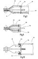
- eine der Darstellung in der
Fig. 1 vergleichbare Darstellung, wobei ein weiteres Ausführungsbeispiel des Arbeitsteils dargestellt ist; - Fig. 7
- eine der Darstellung in
Fig. 5 vergleichbare Darstellung, wobei das Bedienteil mit dem sterilen Schlauch umhüllt ist; - Fig. 8
- einen Längsschnitt im Kopplungsbereich zwischen einem Arbeitsteil und einem Bedienteil mit unterschiedlichen Ausgestaltungen der Lichteinkopplung, in der oberen Hälfte über LEDs im Bedienteil auf Lichtleitfasern im Arbeitsteil, in der unteren Hälfte von Lichtleitfasern im Bedienteil auf Lichtleitfasern im Arbeitsteil;
- Fig. 9
- einen proximalseitigen Längsschnitt einer weiteren Ausgestaltung eines Arbeitsteils mit einer darin integrierten Lichtquelle in Form von LEDs; und
- Fig. 10
- einen Schnitt im Kopplungsbereich zwischen einem Arbeitsteil und einem Bedienteil, wobei Licht vom Bedienteil in radialer Richtung in das Arbeitsteil eingestrahlt wird, in dem es durch Spiegelelemente nach distal gelenkt wird.
- Fig. 1
- a perspective view of a video endoscope according to the invention, wherein a working part and a control panel are separated from each other;
- Fig. 2
- an enlarged perspective view of a proximal end portion of the working part;
- Fig. 3
- an enlarged partial sectional view of a distal end portion of the working part;
- Fig. 4
- an enlarged perspective view of the control panel;
- Fig. 5
- one of the illustration in
Fig. 1 Comparative view, the control panel and the working part are connected; - Fig. 6
- one of the representation in the
Fig. 1 comparable representation, wherein a further embodiment of the working part is shown; - Fig. 7
- one of the illustration in
Fig. 5 Comparative view, wherein the control panel is wrapped with the sterile tube; - Fig. 8
- a longitudinal section in the coupling region between a working part and a control panel with different embodiments of the light coupling, in the upper half via LEDs in the control panel on optical fibers in the working part, in the lower half of optical fibers in the control panel on optical fibers in the working part;
- Fig. 9
- a proximal-side longitudinal section of another embodiment of a working part with a light source integrated therein in the form of LEDs; and
- Fig. 10
- a section in the coupling region between a working part and a control panel, wherein light from the control panel is irradiated in the radial direction in the working part, in which it is deflected by mirror elements to the distal direction.
Ein in den
Das Videoendoskop 10 weist ein Arbeitsteil 12 und ein Bedienteil 14 auf, die über eine Schnittstelle 16 miteinander lösbar verbindbar sind, wie es noch später näher beschrieben wird.The
Das Arbeitsteil 12 ist als Einweginstrument und das Bedienteil 14 ist als Mehrweginstrument ausgebildet.The working
Das Arbeitsteil 12 weist ein Außenteil 18 auf, das in diesem Ausführungsbeispiel als Schaft 20 ausgebildet ist. Der Schaft 20 weist zumindest einen Lichtleiter 26 auf, der Licht von proximal nach distal leitet. In diesem Ausführungsbeispiel ist der Schaft 20 aus einem lichtleitenden Kunststoff ausgebildet.The working
Am proximalen Ende des Arbeitsteils 12 ist ein zusammengeraffter Schlauch 27 angeordnet, dessen genaue Funktionsweise nachstehend mit Bezug auf
Der Schaft 20 ist an seinem distalen Ende 22 mit einem Objektiv 24 hermetisch abgeschlossen, wie es insbesondere aus der vergrößerten Darstellung in
Der aus einem lichtleitenden Kunststoff ausgebildete Schaft 20 wird in einem Spritzgussvorgang hergestellt. Dabei kann gleichzeitig ein Teil des Objektives 24 mit eingespritzt werden.The
Das Arbeitsteil 12 weist ferner ein Innenteil 30 auf, das insbesondere aus der Darstellung in
In dem Innenteil 30 ist ein Bildsensor 32 aufgenommen, der in diesem Ausführungsbeispiel als CMOS-Sensor ausgebildet ist. Der Sensor 32 wandelt die Lichtsignale in elektrische Signale um.In the
Ferner ist in dem Innenteil 30 ein elektrisches Übertragungssystem 34 angeordnet, das die Bildsignale von dem Sensor 32 nach proximal überträgt. In diesem Ausführungsbeispiel ist das elektrische Übertragungssystem 34 als eine durchgehende Platine 36 ausgebildet.Further, in the
Ein distales Ende der Platine 36 ist als ein Stecker 38 ausgebildet, der insbesondere aus der vergrößerten Darstellung in
Der Bildsensor 32 und das als Platine 36 ausgebildete elektrische Übertragungssystem 34 sind von einem zylinderförmigen Element 40 umschlossen. Das aus einer Vergussmasse ausgebildete zylinderförmige Element 40 dient zur Stabilisierung des Bildsensors 32 und der Platine 36 und zur elektrischen Isolation.The
Das Außenteil 18 ist relativ zu dem Innenteil 30 drehbar. Die Drehbarkeit des an dem distalen Ende des Schaftes 20 angeordneten Objektivs 24 gegenüber dem im Innenteil 30 angeordneten Bildsensor 32 ermöglicht die Bildaufrichtung.The
Ferner ist ein Mechanismus 42 zum Drehen des Außenteils 18 vorgesehen. Der Mechanismus 42 kann manuell oder motorisch angetrieben werden.Further, a
Zum manuellen Antreiben des Mechanismus 42 ist ein Betätigungshebel 44 vorgesehen, der proximalseitig an dem Arbeitsteil 12 angeordnet ist. Durch manuelles Drehen des Betätigungshebels 44 wird das Außenteil 18 des Arbeitsteils 12 in Bezug auf das Innenteil 30 gedreht.For manually driving the
Zum motorischen Antreiben des Mechanismus 42 weist das Arbeitsteil 12 eine Zahnung bzw. einen Reibbereich 46 auf, die/der an dem proximalen Ende 48 des Arbeitsteils 12 angeordnet ist. Das Bedienteil 14 weist an seinem distalen Ende 64 dagegen ein Zahnrad bzw. ein Reibrad 72 auf, das nachdem die beiden Elemente 12 und 14 verbunden sind, mit der Zahnung bzw. dem Reibbereich 46 des Arbeitsteils 12 zusammenwirkt.For motorized driving of the
An dem proximalen Ende 48 des Arbeitsteils 12 ist ein Verriegelungselement 50 angeordnet, das zum Verriegeln des Arbeitsteils 12 an dem Bedienteil 14 dient. In diesem Ausführungsbeispiel ist das Verriegelungselement 50 als ein Bolzen 52 ausgebildet.At the
An dem proximalen Ende 48 des Arbeitsteils 12 ist ferner ein ringförmiger Lichteintritt 54 angeordnet, mittels dessen Licht von dem Bedienteil 14 an das Arbeitsteil 12 übertragen wird.At the
Der Bereich 56 gibt hierbei den Bereich wieder, an dem der hier nicht dargestellte Schlauch 27 mit dem Arbeitsteil 12 verbunden ist.The
Das Bedienteil 14 ist als Handgriff 60 ausgebildet, wie das insbesondere aus
Das Bedienteil 14 weist an seinem distalen Ende 64 eine einen Schlitz 68 aufweisende Buchse 66 auf, in den der Stecker 38 der Platine 36 eingeführt wird. Dadurch wird eine elektrische Kopplung geschaffen, die die Übertragung der Bildinformation von dem Bildsensor 32 an das Bedienteil 14 ermöglicht. Die übertragene Bildinformation wird nach einer Bildverarbeitung für den Operateur als Bild auf einem Monitor ersichtlich.The operating
Ferner ist an dem distalen Ende 64 des Bedienteils 14 eine Ausnehmung 70 vorgesehen, in die das als Bolzen 52 ausgebildete Verriegelungselement 50 des Arbeitsteils 12 eingeführt werden kann, wodurch das Arbeitsteil 12 mit dem Bedienteil 14 verbunden wird. Solch eine Situation ist in
An dem distalen Ende 64 des Bedienteils 14 ist ebenfalls ein Lichtaustritt 74 angeordnet, der in diesem Ausführungsbeispiel ringförmig ausgebildet ist. In diesem Ausführungsbeispiel sind an dem Lichtaustritt 72 LEDs 75 angeordnet. Der Lichtaustritt 72 des Bedienteils 14 ist derart angeordnet und ausgebildet, dass er nach Verbinden des Arbeitsteils 12 mit dem Bedienteil 14 mit dem Lichteintritt 54 des Arbeitsteils 12 in Kontakt steht. Dadurch wird Licht von dem Bedienteil 14 an das Arbeitsteil 12 übertragen.At the
An dem als Handgriff 60 ausgebildeten Bedienteil 14 sind Bedienelemente 76, 77, 78, 79 angeordnet, mittels derer die Kamera betätigt wird.On the operating part designed as a
In
Das in
Vor einem chirurgischen Eingriff wird das Arbeitsteil 80 mit dem sterilen Schlauch 58 aus einem hier nicht dargestellten sterilen Überzug entnommen und mit dem nicht sterilisierten Bedienteil 14 verbunden. Dann wird der an dem Arbeitsteil 80 fixierte sterile Schlauch 58 über das als Handgriff 60 ausgebildete Bedienteil 14 gezogen, so dass das nicht sterilisierte Bedienteil 14 mit dem sterilen Schlauch 58 umhüllt ist. Solch eine Situation ist in
Dadurch wird sichergestellt, dass das sterile Arbeitsteil 80 nicht von dem nicht sterilisierten Bedienteil 14 kontaminiert wird. Nach einem Einsatz wird das Arbeitsteil 80 mit dem sterilen Schlauch 27 von dem Bedienteil 14 getrennt und entsorgt.This ensures that the sterile working
In
Im Arbeitsteil 92 sind umfänglich verteilt Lichtleitfasern 93 angeordnet, die vom proximalen bis zum distalen Ende des Arbeitsteiles 92 reichen. In der oberen Hälfte von
In
In
Ist das Bedienteil 116 mit einem Arbeitsteil 112 gekoppelt, das am proximalen Ende verteilte Spiegelelemente 114 aufweist, kann von diesen das radial eingespeiste Beleuchtungslicht nach distal umgelenkt und weitergeleitet werden. Die Weiterleitung kann dann unterschiedlich erfolgen, entweder durch das Material des Arbeitsteils 112 selbst oder durch entsprechende Lichtleitfasern oder dergleichen.If the operating
Alle drei Varianten von
Die in
Claims (24)
Applications Claiming Priority (1)
| Application Number | Priority Date | Filing Date | Title |
|---|---|---|---|
| DE102007026234A DE102007026234A1 (en) | 2007-05-31 | 2007-05-31 | Videoscope |
Publications (2)
| Publication Number | Publication Date |
|---|---|
| EP1997421A1 true EP1997421A1 (en) | 2008-12-03 |
| EP1997421B1 EP1997421B1 (en) | 2012-07-11 |
Family
ID=39758670
Family Applications (1)
| Application Number | Title | Priority Date | Filing Date |
|---|---|---|---|
| EP08009839A Active EP1997421B1 (en) | 2007-05-31 | 2008-05-29 | Video endoscope |
Country Status (3)
| Country | Link |
|---|---|
| US (1) | US20080300456A1 (en) |
| EP (1) | EP1997421B1 (en) |
| DE (1) | DE102007026234A1 (en) |
Cited By (5)
| Publication number | Priority date | Publication date | Assignee | Title |
|---|---|---|---|---|
| WO2013091782A1 (en) * | 2011-12-20 | 2013-06-27 | Olympus Winter & Ibe Gmbh | Video endoscope with sideways viewing direction and method for mounting a video endoscope |
| EP3132296A2 (en) * | 2014-04-17 | 2017-02-22 | Boston Scientific Scimed, Inc. | Self-cleaning optical connector |
| CN109891151A (en) * | 2016-10-13 | 2019-06-14 | 韩国电气研究院 | Medical light source module and the medical light source device for having this |
| WO2019121042A1 (en) * | 2017-12-22 | 2019-06-27 | Olympus Winter & Ibe Gmbh | Video endoscope |
| DE102020119236A1 (en) | 2020-07-21 | 2022-01-27 | Karl Storz Se & Co. Kg | INTERCHANGEABLE STERILE SHAFT FOR AN ENDOSCOPE |
Families Citing this family (34)
| Publication number | Priority date | Publication date | Assignee | Title |
|---|---|---|---|---|
| DE102008033506A1 (en) * | 2008-07-07 | 2010-01-14 | Karl Storz Gmbh & Co. Kg | Video endoscope with switchable semiconductor light sources |
| EP2754385A1 (en) | 2010-09-08 | 2014-07-16 | Covidien LP | Catheter with imaging assembly |
| US8702594B2 (en) * | 2010-10-21 | 2014-04-22 | Avram Allan Edidin | Imaging system having a quick connect coupling interface |
| DE102010052219A1 (en) * | 2010-11-24 | 2012-05-24 | Karl Storz Gmbh & Co. Kg | Holding system for medical instruments |
| GB201121963D0 (en) * | 2011-12-20 | 2012-02-01 | Smiths Medical Int Ltd | Imaging and illumination apparatus |
| DE102012206412A1 (en) * | 2012-04-18 | 2013-10-24 | Karl Storz Gmbh & Co. Kg | Rotary device and method for rotating an endoscope |
| USD716841S1 (en) | 2012-09-07 | 2014-11-04 | Covidien Lp | Display screen with annotate file icon |
| USD735343S1 (en) | 2012-09-07 | 2015-07-28 | Covidien Lp | Console |
| US9517184B2 (en) | 2012-09-07 | 2016-12-13 | Covidien Lp | Feeding tube with insufflation device and related methods therefor |
| USD717340S1 (en) | 2012-09-07 | 2014-11-11 | Covidien Lp | Display screen with enteral feeding icon |
| US9198835B2 (en) | 2012-09-07 | 2015-12-01 | Covidien Lp | Catheter with imaging assembly with placement aid and related methods therefor |
| US10616491B2 (en) | 2013-02-01 | 2020-04-07 | Deka Products Limited Partnership | Endoscope with pannable camera and related method |
| CN105142490B (en) * | 2013-02-01 | 2018-02-23 | 德卡产品有限公司 | With can pan camera endoscope |
| JP6375309B2 (en) | 2013-02-01 | 2018-08-15 | デカ・プロダクツ・リミテッド・パートナーシップ | Endoscope with camera capable of panning |
| US11547446B2 (en) | 2014-01-13 | 2023-01-10 | Trice Medical, Inc. | Fully integrated, disposable tissue visualization device |
| US10869592B2 (en) | 2015-02-23 | 2020-12-22 | Uroviu Corp. | Handheld surgical endoscope |
| EP3334322A1 (en) * | 2015-08-11 | 2018-06-20 | Trice Medical, Inc. | Fully integrated, disposable tissue visualization device |
| USD795424S1 (en) | 2015-09-01 | 2017-08-22 | Deka Products Limited Partnership | Endoscope |
| USD841160S1 (en) | 2016-04-01 | 2019-02-19 | Deka Products Limited Partnership | Endoscope |
| US11684248B2 (en) | 2017-09-25 | 2023-06-27 | Micronvision Corp. | Endoscopy/stereo colposcopy medical instrument |
| US11832797B2 (en) | 2016-09-25 | 2023-12-05 | Micronvision Corp. | Endoscopic fluorescence imaging |
| CN106725262A (en) * | 2016-12-13 | 2017-05-31 | 天津丰茂科技有限公司 | A kind of electromechanical integration endoscopic system and medicine equipment |
| DE102017101681B4 (en) | 2017-01-28 | 2019-01-24 | Olympus Winter & Ibe Gmbh | monitoring tool |
| US10413167B2 (en) | 2017-05-30 | 2019-09-17 | Synaptive Medical (Barbados) Inc. | Micro-optical surgical probes and micro-optical probe tips and methods of manufacture therefor |
| US11771304B1 (en) | 2020-11-12 | 2023-10-03 | Micronvision Corp. | Minimally invasive endoscope |
| DE102018107523A1 (en) | 2018-03-29 | 2019-10-02 | Schott Ag | Light or image guide components for disposable endoscopes |
| WO2019191705A1 (en) | 2018-03-29 | 2019-10-03 | Trice Medical, Inc. | Fully integrated endoscope with biopsy capabilities and methods of use |
| EP3801645A1 (en) * | 2018-06-08 | 2021-04-14 | Pristine Surgical LLC | Endoscope with disposable camera shaft and reuseable handle |
| US11903557B2 (en) | 2019-04-30 | 2024-02-20 | Psip2 Llc | Endoscope for imaging in nonvisible light |
| WO2020234869A1 (en) * | 2019-05-21 | 2020-11-26 | 270 Surgical Ltd. | Detachable shafts for endoscopes |
| DE102019004433A1 (en) * | 2019-06-22 | 2020-12-24 | Karl Storz Se & Co. Kg | Video endoscope and handle for a video endoscope |
| EP4003138A4 (en) | 2019-07-25 | 2023-08-30 | Uroviu Corp. | Disposable endoscopy cannula with integrated grasper |
| DE102019133042A1 (en) | 2019-12-04 | 2021-06-10 | Schott Ag | Endoscope, single-use endoscope system and light source for endoscope |
| DE102020106915A1 (en) * | 2020-03-13 | 2021-09-16 | Schott Ag | Endoscope and single-use endoscope system |
Citations (5)
| Publication number | Priority date | Publication date | Assignee | Title |
|---|---|---|---|---|
| JPH06254049A (en) * | 1993-03-01 | 1994-09-13 | Olympus Optical Co Ltd | Endoscope |
| EP1201179A1 (en) * | 2000-10-24 | 2002-05-02 | Karl Storz GmbH & Co. KG | White-light source using LEDs for an endoscope |
| US20020193664A1 (en) * | 1999-12-29 | 2002-12-19 | Ross Ian Michael | Light source for borescopes and endoscopes |
| DE102004023866B3 (en) * | 2004-05-12 | 2006-02-23 | Olympus Winter & Ibe Gmbh | Video endoscope has tube containing rotatable video camera with multiple connection leads on flexible circuit |
| EP1721568A1 (en) | 2004-03-02 | 2006-11-15 | Olympus Corporation | Endoscope |
Family Cites Families (86)
| Publication number | Priority date | Publication date | Assignee | Title |
|---|---|---|---|---|
| US4522196A (en) * | 1982-06-11 | 1985-06-11 | Cunningham Frank W | Reusable, sterile covering for a surgical camera |
| JPS60125610U (en) * | 1984-02-03 | 1985-08-24 | オリンパス光学工業株式会社 | Strabismus-type rigid endoscope |
| US4646722A (en) * | 1984-12-10 | 1987-03-03 | Opielab, Inc. | Protective endoscope sheath and method of installing same |
| US4741326A (en) * | 1986-10-01 | 1988-05-03 | Fujinon, Inc. | Endoscope disposable sheath |
| US4905082A (en) * | 1987-05-06 | 1990-02-27 | Olympus Optical Co., Ltd. | Rigid video endoscope having a detachable imaging unit |
| DE8815549U1 (en) * | 1988-09-23 | 1989-02-23 | Herzberg, Wolfgang, Dr. Med., 2000 Wedel, De | |
| US4878485A (en) * | 1989-02-03 | 1989-11-07 | Adair Edwin Lloyd | Rigid video endoscope with heat sterilizable sheath |
| US5168863A (en) * | 1990-08-27 | 1992-12-08 | Medical Concepts, Inc. | Sterile endoscopic system |
| US5237984A (en) * | 1991-06-24 | 1993-08-24 | Xomed-Treace Inc. | Sheath for endoscope |
| WO1993015648A1 (en) * | 1992-02-07 | 1993-08-19 | Wilk Peter J | Endoscope with disposable insertion member |
| US5704892A (en) | 1992-09-01 | 1998-01-06 | Adair; Edwin L. | Endoscope with reusable core and disposable sheath with passageways |
| US5339800A (en) * | 1992-09-10 | 1994-08-23 | Devmed Group Inc. | Lens cleaning means for invasive viewing medical instruments with anti-contamination means |
| WO1994009694A1 (en) * | 1992-10-28 | 1994-05-11 | Arsenault, Dennis, J. | Electronic endoscope |
| US5423312A (en) * | 1992-12-18 | 1995-06-13 | Schott Fiber Optics, Inc. | Rigid endoscope having modified high refractive index tunnel rod for image transmission and method of manufacture thereof |
| US5863286A (en) * | 1993-01-27 | 1999-01-26 | Olympus Optical Company, Ltd. | Endoscope system including endoscope and disposable protection cover |
| US5688221A (en) * | 1993-02-12 | 1997-11-18 | Olympus Optical Co., Ltd. | Endoscope cover for endoscope system having uniform flexibility |
| US5630787A (en) * | 1993-02-18 | 1997-05-20 | Olympus Optical Co., Ltd. | System including endoscope and disposable protection cover with channel |
| US5575752A (en) * | 1993-02-19 | 1996-11-19 | Olympus Optical Co., Ltd. | Endoscope system, cover type endoscope unit, channeled cover type endoscope unit, holding tool in endoscope system, and housing member of cover type endoscope unit |
| US5487376A (en) * | 1993-02-25 | 1996-01-30 | Olympus Optical Co., Ltd. | Washing apparatus for a protection cover for an endoscope |
| US5674182A (en) * | 1993-02-26 | 1997-10-07 | Olympus Optical Co., Ltd. | Endoscope system including endoscope and protection cover |
| US5554098A (en) * | 1993-02-26 | 1996-09-10 | Olympus Optical Co., Ltd. | Endoscope system including endoscope and disposable protection cover |
| US5575753A (en) * | 1993-03-05 | 1996-11-19 | Olympus Optical Co., Ltd. | Endoscopic apparatus using a covered type endoscope fitted in an endoscope cover |
| US5674180A (en) * | 1993-03-15 | 1997-10-07 | Olympus Optical Co., Ltd. | Endoscope system including endoscope and disposable protection cover |
| US5551945A (en) * | 1993-03-16 | 1996-09-03 | Olympus Optical Co., Ltd. | Endoscope system including endoscope and protection cover |
| US5695447A (en) * | 1993-03-16 | 1997-12-09 | Olympus Optical Company, Ltd. | Endoscope system including endoscope and disposable protection cover |
| US5817015A (en) * | 1993-06-22 | 1998-10-06 | Adair; Edwin L. | Endoscope with reusable core and disposable sheath with passageways |
| IL106868A0 (en) * | 1993-09-02 | 1993-12-28 | Nmb Medical Applic Ltd | Disposable cystoscope |
| US5496259A (en) * | 1993-09-13 | 1996-03-05 | Welch Allyn, Inc. | Sterile protective sheath and drape for video laparoscope and method of use |
| US5852511A (en) * | 1993-10-20 | 1998-12-22 | Olympus Optical Co. Ltd | Optical system for non-flexible endoscopes |
| US5632718A (en) * | 1994-03-11 | 1997-05-27 | Olympus Optical Co., Ltd. | Non-flexible endoscope with objective lens system and relay lens system |
| US5498230A (en) * | 1994-10-03 | 1996-03-12 | Adair; Edwin L. | Sterile connector and video camera cover for sterile endoscope |
| US5792045A (en) * | 1994-10-03 | 1998-08-11 | Adair; Edwin L. | Sterile surgical coupler and drape |
| US5433221A (en) * | 1994-10-05 | 1995-07-18 | Adair; Edwin L. | Windowed self-centering drape for surgical camera |
| JP3461974B2 (en) * | 1995-05-31 | 2003-10-27 | 株式会社町田製作所 | Endoscope |
| US5621830A (en) * | 1995-06-07 | 1997-04-15 | Smith & Nephew Dyonics Inc. | Rotatable fiber optic joint |
| US5797836A (en) * | 1995-06-07 | 1998-08-25 | Smith & Nephew, Inc. | Endoscope with relative rotation and axial motion between an optical element and an imaging device |
| US6004263A (en) * | 1996-03-13 | 1999-12-21 | Hihon Kohden Corporation | Endoscope with detachable operation unit and insertion unit |
| US6221007B1 (en) * | 1996-05-03 | 2001-04-24 | Philip S. Green | System and method for endoscopic imaging and endosurgery |
| US5873814A (en) * | 1996-07-12 | 1999-02-23 | Adair; Edwin L. | Sterile encapsulated endoscopic video monitor and method |
| US7018331B2 (en) * | 1996-08-26 | 2006-03-28 | Stryker Corporation | Endoscope assembly useful with a scope-sensing light cable |
| US6221070B1 (en) * | 1996-10-18 | 2001-04-24 | Irvine Biomedical, Inc. | Steerable ablation catheter system having disposable shaft |
| CN1217637A (en) * | 1997-02-13 | 1999-05-26 | 松下电器产业株式会社 | Endoscope, method of manufacturing same, and inserting member |
| US5876328A (en) * | 1997-04-23 | 1999-03-02 | Endolap, Inc. | Surgical camera drape assembly and method |
| US5929901A (en) * | 1997-10-06 | 1999-07-27 | Adair; Edwin L. | Reduced area imaging devices incorporated within surgical instruments |
| DE19839188C2 (en) * | 1998-08-28 | 2003-08-21 | Storz Endoskop Gmbh Schaffhaus | endoscope |
| US7180600B2 (en) * | 1998-09-21 | 2007-02-20 | Olympus Corporation | Optical imaging apparatus |
| US6615072B1 (en) * | 1999-02-04 | 2003-09-02 | Olympus Optical Co., Ltd. | Optical imaging device |
| JP2001008892A (en) * | 1999-06-28 | 2001-01-16 | Asahi Optical Co Ltd | Light source device and endoscope system |
| US20020087047A1 (en) * | 1999-09-13 | 2002-07-04 | Visionscope, Inc. | Miniature endoscope system |
| DE19955229C1 (en) * | 1999-11-17 | 2001-08-09 | Winter & Ibe Olympus | Endoscope with distal video camera and camera rotating device |
| US6699179B2 (en) * | 2000-01-27 | 2004-03-02 | Scimed Life Systems, Inc. | Catheter introducer system for exploration of body cavities |
| US6808505B2 (en) * | 2000-02-01 | 2004-10-26 | Kadan Jeffrey S | Diagnostic needle arthroscopy and lavage system |
| US6855106B2 (en) * | 2000-03-16 | 2005-02-15 | Medivision, Inc. | Endoscope and camera mount |
| US20050197533A1 (en) * | 2000-03-16 | 2005-09-08 | Medivision, Inc. | Endoscope and camera mount |
| JP3782927B2 (en) * | 2000-09-04 | 2006-06-07 | フジノン株式会社 | Endoscopic linear transmission member driving apparatus |
| US6921920B2 (en) * | 2001-08-31 | 2005-07-26 | Smith & Nephew, Inc. | Solid-state light source |
| US8038602B2 (en) * | 2001-10-19 | 2011-10-18 | Visionscope Llc | Portable imaging system employing a miniature endoscope |
| US10595710B2 (en) * | 2001-10-19 | 2020-03-24 | Visionscope Technologies Llc | Portable imaging system employing a miniature endoscope |
| US6863651B2 (en) * | 2001-10-19 | 2005-03-08 | Visionscope, Llc | Miniature endoscope with imaging fiber system |
| US20070167681A1 (en) * | 2001-10-19 | 2007-07-19 | Gill Thomas J | Portable imaging system employing a miniature endoscope |
| US6852077B2 (en) * | 2001-11-01 | 2005-02-08 | Pentax Corporation | Cover for preventing contamination of an operating portion of an endoscope |
| US20030195390A1 (en) * | 2002-03-11 | 2003-10-16 | Graumann Martin Panczel | Digital laryngoscope |
| US6856436B2 (en) * | 2002-06-26 | 2005-02-15 | Innovations In Optics, Inc. | Scanning light source system |
| US6908428B2 (en) * | 2003-09-04 | 2005-06-21 | Sightline Technologies Ltd. | Sleeve for endoscopic tools |
| US7946981B1 (en) * | 2003-10-23 | 2011-05-24 | Anthony Cubb | Two-piece video laryngoscope |
| DE102004009384B4 (en) * | 2004-02-26 | 2005-12-22 | Olympus Winter & Ibe Gmbh | Video endoscopic system |
| WO2005082228A1 (en) * | 2004-02-26 | 2005-09-09 | Olympus Corporation | Endoscope and endoscope system |
| EP1750569B1 (en) * | 2004-03-23 | 2012-05-09 | California Institute Of Technology | Forward scanning imaging optical fiber probe |
| EP1737335B1 (en) * | 2004-03-23 | 2013-05-15 | Boston Scientific Limited | In-vivo visualization system |
| US7364543B2 (en) * | 2004-03-23 | 2008-04-29 | California Institute Of Technology | Paired angled rotation scanning probes and methods of use |
| WO2005110195A1 (en) * | 2004-05-14 | 2005-11-24 | Olympus Corporation | Insertion device |
| US20050279354A1 (en) * | 2004-06-21 | 2005-12-22 | Harvey Deutsch | Structures and Methods for the Joint Delivery of Fluids and Light |
| US7335159B2 (en) * | 2004-08-26 | 2008-02-26 | Scimed Life Systems, Inc. | Endoscope having auto-insufflation and exsufflation |
| DE102004044119B4 (en) * | 2004-09-11 | 2016-11-03 | Olympus Winter & Ibe Gmbh | Video endoscope with rotatable video camera |
| US8602971B2 (en) * | 2004-09-24 | 2013-12-10 | Vivid Medical. Inc. | Opto-Electronic illumination and vision module for endoscopy |
| US8480566B2 (en) * | 2004-09-24 | 2013-07-09 | Vivid Medical, Inc. | Solid state illumination for endoscopy |
| US8029439B2 (en) * | 2005-01-28 | 2011-10-04 | Stryker Corporation | Disposable attachable light source unit for an endoscope |
| JP4668643B2 (en) * | 2005-02-23 | 2011-04-13 | オリンパスメディカルシステムズ株式会社 | Endoscope device |
| US7510524B2 (en) * | 2005-04-04 | 2009-03-31 | Invuity, Inc. | Optical waveguide sheath |
| JP2007135947A (en) * | 2005-11-21 | 2007-06-07 | Fujifilm Corp | Optical probe and optical tomographic imaging system |
| WO2007075989A2 (en) * | 2005-12-20 | 2007-07-05 | Orthodynamix Llc | Method and devices for minimally invasive arthroscopic procedures |
| FR2899087B1 (en) * | 2006-04-03 | 2008-06-20 | V I M S Video Interventionnell | PROTECTION FOR ENDOSCOPE AND CORRESPONDING ENDOSCOPE |
| US20080039693A1 (en) * | 2006-08-14 | 2008-02-14 | University Of Washington | Endoscope tip unit and endoscope with scanning optical fiber |
| JP2010506669A (en) * | 2006-10-20 | 2010-03-04 | フェムスイート, エルエルシー | Optical surgical device and method of use thereof |
| DE102007009292A1 (en) * | 2007-02-16 | 2008-08-21 | Karl Storz Gmbh & Co. Kg | Videoscope |
| CN102038479B (en) * | 2009-10-23 | 2012-05-23 | 姜克让 | Disposable protecting jacket for endoscope |
-
2007
- 2007-05-31 DE DE102007026234A patent/DE102007026234A1/en not_active Withdrawn
-
2008
- 2008-05-29 EP EP08009839A patent/EP1997421B1/en active Active
- 2008-05-30 US US12/130,748 patent/US20080300456A1/en not_active Abandoned
Patent Citations (5)
| Publication number | Priority date | Publication date | Assignee | Title |
|---|---|---|---|---|
| JPH06254049A (en) * | 1993-03-01 | 1994-09-13 | Olympus Optical Co Ltd | Endoscope |
| US20020193664A1 (en) * | 1999-12-29 | 2002-12-19 | Ross Ian Michael | Light source for borescopes and endoscopes |
| EP1201179A1 (en) * | 2000-10-24 | 2002-05-02 | Karl Storz GmbH & Co. KG | White-light source using LEDs for an endoscope |
| EP1721568A1 (en) | 2004-03-02 | 2006-11-15 | Olympus Corporation | Endoscope |
| DE102004023866B3 (en) * | 2004-05-12 | 2006-02-23 | Olympus Winter & Ibe Gmbh | Video endoscope has tube containing rotatable video camera with multiple connection leads on flexible circuit |
Cited By (9)
| Publication number | Priority date | Publication date | Assignee | Title |
|---|---|---|---|---|
| WO2013091782A1 (en) * | 2011-12-20 | 2013-06-27 | Olympus Winter & Ibe Gmbh | Video endoscope with sideways viewing direction and method for mounting a video endoscope |
| US9717396B2 (en) | 2011-12-20 | 2017-08-01 | Olympus Winter & Ibe Gmbh | Video endoscope with sideways viewing direction and method for mounting a video endoscope |
| EP3132296A2 (en) * | 2014-04-17 | 2017-02-22 | Boston Scientific Scimed, Inc. | Self-cleaning optical connector |
| EP3132296B1 (en) * | 2014-04-17 | 2023-01-04 | Boston Scientific Scimed, Inc. | Self-cleaning optical connector |
| CN109891151A (en) * | 2016-10-13 | 2019-06-14 | 韩国电气研究院 | Medical light source module and the medical light source device for having this |
| CN109891151B (en) * | 2016-10-13 | 2021-03-23 | 韩国电气研究院 | Medical light source module and medical light source device provided with same |
| WO2019121042A1 (en) * | 2017-12-22 | 2019-06-27 | Olympus Winter & Ibe Gmbh | Video endoscope |
| US11426057B2 (en) | 2017-12-22 | 2022-08-30 | Olympus Winter & Ibe Gmbh | Video endoscope having fastener absorbing torsional forces acting on signal line connected to image sensor |
| DE102020119236A1 (en) | 2020-07-21 | 2022-01-27 | Karl Storz Se & Co. Kg | INTERCHANGEABLE STERILE SHAFT FOR AN ENDOSCOPE |
Also Published As
| Publication number | Publication date |
|---|---|
| DE102007026234A1 (en) | 2008-12-04 |
| US20080300456A1 (en) | 2008-12-04 |
| EP1997421B1 (en) | 2012-07-11 |
Similar Documents
| Publication | Publication Date | Title |
|---|---|---|
| EP1997421B1 (en) | Video endoscope | |
| DE102005014529B4 (en) | ultrasound endoscope | |
| DE10348188B4 (en) | An ultrasonic endoscope | |
| EP2676597B1 (en) | Endoscope sheath, endoscope system and method for providing an endoscope system | |
| EP1972259B1 (en) | Deflectable autoclaving endoscope | |
| DE19924361C2 (en) | endoscope | |
| EP3787471A1 (en) | Endoscope deflection using a distal folding mechanism | |
| DE102010053814B4 (en) | Endoscope for medical purposes | |
| DE19947811C2 (en) | Endoscope with electrical equipment and light guide | |
| DE112012005999T5 (en) | Endoscopic multifunction device for medical therapy | |
| EP2200497A1 (en) | Modular endoscope | |
| EP1164917A1 (en) | Device for intracorporeal, minimal invasive treatment of a patient | |
| DE102012206412A1 (en) | Rotary device and method for rotating an endoscope | |
| DE102017107978B4 (en) | Endoscope head with swiveling camera and working channel unit | |
| DE102011054031A1 (en) | exoscope | |
| EP2438844A2 (en) | Articulated section of a shaft for an endoscopic instrument | |
| DE102012008537A1 (en) | Surgical robot system has robot that is releasably fixed to instrument arrangement, and instrument interface that is arranged between drive unit and instrument | |
| EP3720333A1 (en) | Endoscope having a pivotable handle part | |
| EP4011271A1 (en) | Endoscope with rotary drum and operating method | |
| EP2417899B1 (en) | Shaft element for an endoscopic instrument | |
| DE102019102599A1 (en) | Endoscope with distal swivel mechanism and fine adjustment | |
| WO2017025434A1 (en) | Endoscope head, endoscope, cap and cap forming method | |
| EP1997452B1 (en) | Device for providing a sterile wrapping for a sterilisation sensitive control | |
| DE102011089132B4 (en) | Video endoscope with lateral viewing direction | |
| DE10122709B4 (en) | Radially scanning, forward-looking ultrasound endoscope |
Legal Events
| Date | Code | Title | Description |
|---|---|---|---|
| PUAI | Public reference made under article 153(3) epc to a published international application that has entered the european phase |
Free format text: ORIGINAL CODE: 0009012 |
|
| AK | Designated contracting states |
Kind code of ref document: A1 Designated state(s): AT BE BG CH CY CZ DE DK EE ES FI FR GB GR HR HU IE IS IT LI LT LU LV MC MT NL NO PL PT RO SE SI SK TR |
|
| AX | Request for extension of the european patent |
Extension state: AL BA MK RS |
|
| 17P | Request for examination filed |
Effective date: 20090527 |
|
| AKX | Designation fees paid |
Designated state(s): AT BE BG CH CY CZ DE DK EE ES FI FR GB GR HR HU IE IS IT LI LT LU LV MC MT NL NO PL PT RO SE SI SK TR |
|
| GRAP | Despatch of communication of intention to grant a patent |
Free format text: ORIGINAL CODE: EPIDOSNIGR1 |
|
| GRAS | Grant fee paid |
Free format text: ORIGINAL CODE: EPIDOSNIGR3 |
|
| GRAA | (expected) grant |
Free format text: ORIGINAL CODE: 0009210 |
|
| AK | Designated contracting states |
Kind code of ref document: B1 Designated state(s): AT BE BG CH CY CZ DE DK EE ES FI FR GB GR HR HU IE IS IT LI LT LU LV MC MT NL NO PL PT RO SE SI SK TR |
|
| REG | Reference to a national code |
Ref country code: GB Ref legal event code: FG4D Free format text: NOT ENGLISH |
|
| REG | Reference to a national code |
Ref country code: CH Ref legal event code: EP |
|
| REG | Reference to a national code |
Ref country code: AT Ref legal event code: REF Ref document number: 565633 Country of ref document: AT Kind code of ref document: T Effective date: 20120715 |
|
| REG | Reference to a national code |
Ref country code: IE Ref legal event code: FG4D Free format text: LANGUAGE OF EP DOCUMENT: GERMAN |
|
| REG | Reference to a national code |
Ref country code: DE Ref legal event code: R096 Ref document number: 502008007673 Country of ref document: DE Effective date: 20120906 |
|
| REG | Reference to a national code |
Ref country code: NL Ref legal event code: VDEP Effective date: 20120711 |
|
| REG | Reference to a national code |
Ref country code: LT Ref legal event code: MG4D Effective date: 20120711 |
|
| PG25 | Lapsed in a contracting state [announced via postgrant information from national office to epo] |
Ref country code: FI Free format text: LAPSE BECAUSE OF FAILURE TO SUBMIT A TRANSLATION OF THE DESCRIPTION OR TO PAY THE FEE WITHIN THE PRESCRIBED TIME-LIMIT Effective date: 20120711 Ref country code: NO Free format text: LAPSE BECAUSE OF FAILURE TO SUBMIT A TRANSLATION OF THE DESCRIPTION OR TO PAY THE FEE WITHIN THE PRESCRIBED TIME-LIMIT Effective date: 20121011 Ref country code: IS Free format text: LAPSE BECAUSE OF FAILURE TO SUBMIT A TRANSLATION OF THE DESCRIPTION OR TO PAY THE FEE WITHIN THE PRESCRIBED TIME-LIMIT Effective date: 20121111 Ref country code: HR Free format text: LAPSE BECAUSE OF FAILURE TO SUBMIT A TRANSLATION OF THE DESCRIPTION OR TO PAY THE FEE WITHIN THE PRESCRIBED TIME-LIMIT Effective date: 20120711 Ref country code: LT Free format text: LAPSE BECAUSE OF FAILURE TO SUBMIT A TRANSLATION OF THE DESCRIPTION OR TO PAY THE FEE WITHIN THE PRESCRIBED TIME-LIMIT Effective date: 20120711 Ref country code: CY Free format text: LAPSE BECAUSE OF FAILURE TO SUBMIT A TRANSLATION OF THE DESCRIPTION OR TO PAY THE FEE WITHIN THE PRESCRIBED TIME-LIMIT Effective date: 20120711 |
|
| PG25 | Lapsed in a contracting state [announced via postgrant information from national office to epo] |
Ref country code: GR Free format text: LAPSE BECAUSE OF FAILURE TO SUBMIT A TRANSLATION OF THE DESCRIPTION OR TO PAY THE FEE WITHIN THE PRESCRIBED TIME-LIMIT Effective date: 20121012 Ref country code: SE Free format text: LAPSE BECAUSE OF FAILURE TO SUBMIT A TRANSLATION OF THE DESCRIPTION OR TO PAY THE FEE WITHIN THE PRESCRIBED TIME-LIMIT Effective date: 20120711 Ref country code: LV Free format text: LAPSE BECAUSE OF FAILURE TO SUBMIT A TRANSLATION OF THE DESCRIPTION OR TO PAY THE FEE WITHIN THE PRESCRIBED TIME-LIMIT Effective date: 20120711 Ref country code: PL Free format text: LAPSE BECAUSE OF FAILURE TO SUBMIT A TRANSLATION OF THE DESCRIPTION OR TO PAY THE FEE WITHIN THE PRESCRIBED TIME-LIMIT Effective date: 20120711 Ref country code: PT Free format text: LAPSE BECAUSE OF FAILURE TO SUBMIT A TRANSLATION OF THE DESCRIPTION OR TO PAY THE FEE WITHIN THE PRESCRIBED TIME-LIMIT Effective date: 20121112 Ref country code: SI Free format text: LAPSE BECAUSE OF FAILURE TO SUBMIT A TRANSLATION OF THE DESCRIPTION OR TO PAY THE FEE WITHIN THE PRESCRIBED TIME-LIMIT Effective date: 20120711 |
|
| PG25 | Lapsed in a contracting state [announced via postgrant information from national office to epo] |
Ref country code: NL Free format text: LAPSE BECAUSE OF FAILURE TO SUBMIT A TRANSLATION OF THE DESCRIPTION OR TO PAY THE FEE WITHIN THE PRESCRIBED TIME-LIMIT Effective date: 20120711 |
|
| PG25 | Lapsed in a contracting state [announced via postgrant information from national office to epo] |
Ref country code: DK Free format text: LAPSE BECAUSE OF FAILURE TO SUBMIT A TRANSLATION OF THE DESCRIPTION OR TO PAY THE FEE WITHIN THE PRESCRIBED TIME-LIMIT Effective date: 20120711 Ref country code: RO Free format text: LAPSE BECAUSE OF FAILURE TO SUBMIT A TRANSLATION OF THE DESCRIPTION OR TO PAY THE FEE WITHIN THE PRESCRIBED TIME-LIMIT Effective date: 20120711 Ref country code: EE Free format text: LAPSE BECAUSE OF FAILURE TO SUBMIT A TRANSLATION OF THE DESCRIPTION OR TO PAY THE FEE WITHIN THE PRESCRIBED TIME-LIMIT Effective date: 20120711 Ref country code: ES Free format text: LAPSE BECAUSE OF FAILURE TO SUBMIT A TRANSLATION OF THE DESCRIPTION OR TO PAY THE FEE WITHIN THE PRESCRIBED TIME-LIMIT Effective date: 20121022 Ref country code: CZ Free format text: LAPSE BECAUSE OF FAILURE TO SUBMIT A TRANSLATION OF THE DESCRIPTION OR TO PAY THE FEE WITHIN THE PRESCRIBED TIME-LIMIT Effective date: 20120711 |
|
| PLBE | No opposition filed within time limit |
Free format text: ORIGINAL CODE: 0009261 |
|
| STAA | Information on the status of an ep patent application or granted ep patent |
Free format text: STATUS: NO OPPOSITION FILED WITHIN TIME LIMIT |
|
| PG25 | Lapsed in a contracting state [announced via postgrant information from national office to epo] |
Ref country code: SK Free format text: LAPSE BECAUSE OF FAILURE TO SUBMIT A TRANSLATION OF THE DESCRIPTION OR TO PAY THE FEE WITHIN THE PRESCRIBED TIME-LIMIT Effective date: 20120711 |
|
| 26N | No opposition filed |
Effective date: 20130412 |
|
| PG25 | Lapsed in a contracting state [announced via postgrant information from national office to epo] |
Ref country code: BG Free format text: LAPSE BECAUSE OF FAILURE TO SUBMIT A TRANSLATION OF THE DESCRIPTION OR TO PAY THE FEE WITHIN THE PRESCRIBED TIME-LIMIT Effective date: 20121011 |
|
| REG | Reference to a national code |
Ref country code: DE Ref legal event code: R097 Ref document number: 502008007673 Country of ref document: DE Effective date: 20130412 |
|
| BERE | Be: lapsed |
Owner name: KARL STORZ G.M.B.H. & CO. KG Effective date: 20130531 |
|
| PG25 | Lapsed in a contracting state [announced via postgrant information from national office to epo] |
Ref country code: MC Free format text: LAPSE BECAUSE OF FAILURE TO SUBMIT A TRANSLATION OF THE DESCRIPTION OR TO PAY THE FEE WITHIN THE PRESCRIBED TIME-LIMIT Effective date: 20120711 |
|
| REG | Reference to a national code |
Ref country code: CH Ref legal event code: PL |
|
| PG25 | Lapsed in a contracting state [announced via postgrant information from national office to epo] |
Ref country code: CH Free format text: LAPSE BECAUSE OF NON-PAYMENT OF DUE FEES Effective date: 20130531 Ref country code: LI Free format text: LAPSE BECAUSE OF NON-PAYMENT OF DUE FEES Effective date: 20130531 |
|
| REG | Reference to a national code |
Ref country code: IE Ref legal event code: MM4A |
|
| PG25 | Lapsed in a contracting state [announced via postgrant information from national office to epo] |
Ref country code: BE Free format text: LAPSE BECAUSE OF NON-PAYMENT OF DUE FEES Effective date: 20130531 |
|
| PG25 | Lapsed in a contracting state [announced via postgrant information from national office to epo] |
Ref country code: IE Free format text: LAPSE BECAUSE OF NON-PAYMENT OF DUE FEES Effective date: 20130529 |
|
| REG | Reference to a national code |
Ref country code: AT Ref legal event code: MM01 Ref document number: 565633 Country of ref document: AT Kind code of ref document: T Effective date: 20130529 |
|
| PG25 | Lapsed in a contracting state [announced via postgrant information from national office to epo] |
Ref country code: AT Free format text: LAPSE BECAUSE OF NON-PAYMENT OF DUE FEES Effective date: 20130529 |
|
| PG25 | Lapsed in a contracting state [announced via postgrant information from national office to epo] |
Ref country code: MT Free format text: LAPSE BECAUSE OF FAILURE TO SUBMIT A TRANSLATION OF THE DESCRIPTION OR TO PAY THE FEE WITHIN THE PRESCRIBED TIME-LIMIT Effective date: 20120711 |
|
| PG25 | Lapsed in a contracting state [announced via postgrant information from national office to epo] |
Ref country code: TR Free format text: LAPSE BECAUSE OF FAILURE TO SUBMIT A TRANSLATION OF THE DESCRIPTION OR TO PAY THE FEE WITHIN THE PRESCRIBED TIME-LIMIT Effective date: 20120711 |
|
| PG25 | Lapsed in a contracting state [announced via postgrant information from national office to epo] |
Ref country code: LU Free format text: LAPSE BECAUSE OF NON-PAYMENT OF DUE FEES Effective date: 20130529 Ref country code: HU Free format text: LAPSE BECAUSE OF FAILURE TO SUBMIT A TRANSLATION OF THE DESCRIPTION OR TO PAY THE FEE WITHIN THE PRESCRIBED TIME-LIMIT; INVALID AB INITIO Effective date: 20080529 |
|
| REG | Reference to a national code |
Ref country code: FR Ref legal event code: PLFP Year of fee payment: 9 |
|
| REG | Reference to a national code |
Ref country code: FR Ref legal event code: PLFP Year of fee payment: 10 |
|
| REG | Reference to a national code |
Ref country code: FR Ref legal event code: PLFP Year of fee payment: 11 |
|
| PGFP | Annual fee paid to national office [announced via postgrant information from national office to epo] |
Ref country code: IT Payment date: 20180420 Year of fee payment: 11 |
|
| REG | Reference to a national code |
Ref country code: DE Ref legal event code: R081 Ref document number: 502008007673 Country of ref document: DE Owner name: STORZ ENDOSKOP PRODUKTIONS GMBH, CH Free format text: FORMER OWNER: KARL STORZ GMBH & CO. KG, 78532 TUTTLINGEN, DE Ref country code: DE Ref legal event code: R082 Ref document number: 502008007673 Country of ref document: DE Representative=s name: WITTE, WELLER & PARTNER PATENTANWAELTE MBB, DE |
|
| REG | Reference to a national code |
Ref country code: GB Ref legal event code: 732E Free format text: REGISTERED BETWEEN 20190117 AND 20190123 |
|
| PG25 | Lapsed in a contracting state [announced via postgrant information from national office to epo] |
Ref country code: IT Free format text: LAPSE BECAUSE OF NON-PAYMENT OF DUE FEES Effective date: 20190529 |
|
| P01 | Opt-out of the competence of the unified patent court (upc) registered |
Effective date: 20230527 |
|
| PGFP | Annual fee paid to national office [announced via postgrant information from national office to epo] |
Ref country code: FR Payment date: 20230420 Year of fee payment: 16 Ref country code: DE Payment date: 20230419 Year of fee payment: 16 |
|
| PGFP | Annual fee paid to national office [announced via postgrant information from national office to epo] |
Ref country code: GB Payment date: 20230420 Year of fee payment: 16 |