EP1997393A2 - Method of increasing the efficiency of drier, particularly a stream drier - Google Patents
Method of increasing the efficiency of drier, particularly a stream drier Download PDFInfo
- Publication number
- EP1997393A2 EP1997393A2 EP08156948A EP08156948A EP1997393A2 EP 1997393 A2 EP1997393 A2 EP 1997393A2 EP 08156948 A EP08156948 A EP 08156948A EP 08156948 A EP08156948 A EP 08156948A EP 1997393 A2 EP1997393 A2 EP 1997393A2
- Authority
- EP
- European Patent Office
- Prior art keywords
- drier
- steam
- stream
- process gas
- drying agent
- Prior art date
- Legal status (The legal status is an assumption and is not a legal conclusion. Google has not performed a legal analysis and makes no representation as to the accuracy of the status listed.)
- Granted
Links
Images

Classifications
-
- A—HUMAN NECESSITIES
- A24—TOBACCO; CIGARS; CIGARETTES; SIMULATED SMOKING DEVICES; SMOKERS' REQUISITES
- A24B—MANUFACTURE OR PREPARATION OF TOBACCO FOR SMOKING OR CHEWING; TOBACCO; SNUFF
- A24B3/00—Preparing tobacco in the factory
- A24B3/04—Humidifying or drying tobacco bunches or cut tobacco
-
- F—MECHANICAL ENGINEERING; LIGHTING; HEATING; WEAPONS; BLASTING
- F26—DRYING
- F26B—DRYING SOLID MATERIALS OR OBJECTS BY REMOVING LIQUID THEREFROM
- F26B17/00—Machines or apparatus for drying materials in loose, plastic, or fluidised form, e.g. granules, staple fibres, with progressive movement
- F26B17/10—Machines or apparatus for drying materials in loose, plastic, or fluidised form, e.g. granules, staple fibres, with progressive movement with movement performed by fluid currents, e.g. issuing from a nozzle, e.g. pneumatic, flash, vortex or entrainment dryers
- F26B17/101—Machines or apparatus for drying materials in loose, plastic, or fluidised form, e.g. granules, staple fibres, with progressive movement with movement performed by fluid currents, e.g. issuing from a nozzle, e.g. pneumatic, flash, vortex or entrainment dryers the drying enclosure having the shape of one or a plurality of shafts or ducts, e.g. with substantially straight and vertical axis
-
- F—MECHANICAL ENGINEERING; LIGHTING; HEATING; WEAPONS; BLASTING
- F26—DRYING
- F26B—DRYING SOLID MATERIALS OR OBJECTS BY REMOVING LIQUID THEREFROM
- F26B21/00—Arrangements for supplying or controlling air or other gases for drying solid materials or objects
- F26B21/20—Circulating air or gases in closed cycles, e.g. wholly within the drying enclosure
- F26B21/25—Circulating air or gases in closed cycles, e.g. wholly within the drying enclosure partly outside the drying enclosure
-
- F—MECHANICAL ENGINEERING; LIGHTING; HEATING; WEAPONS; BLASTING
- F26—DRYING
- F26B—DRYING SOLID MATERIALS OR OBJECTS BY REMOVING LIQUID THEREFROM
- F26B2200/00—Drying processes and machines for solid materials characterised by the specific requirements of the drying goods
- F26B2200/22—Tobacco leaves
Definitions
- This invention relates to a method of increasing the efficiency of a drier, particularly a stream drier, used for dry loose and flammable materials.
- the invention relates particularly to driers for cut tobacco, working with the use of a gaseous drying agent, particularly superheated steam.
- driers are known in the art, especially stream driers, working with a gaseous drying agent, in which superheated steam is used as a process gas of a temperature close or even higher than the ignition temperature of the dried material.
- Oxygen contained in the air delivered into the drier may cause an explosion or fire, and also it is a reagent in chemical processes, which affects properties of the material. Due to their operation principle, dosing-separating valves, used so far, let the air (oxygen) into the drier, leading to disadvantageous changes in the composition of the process gas. Its regeneration needs significant expenditure of energy for the process of removing the oxygen from the whole volume of the process gas contained in the drier.
- EP 0528227 A1 describes a method of drying tobacco material in a stream drier, in which, preferably, superheated steam is used as a drying agent.
- a double rotary vane feeder is used, separating the stream drier from the surroundings and making it possible to feed the tobacco material to the drier.
- Another single feeder is located in the output conduit from the gas separator situated in the drier.
- U.S. patent description No 4 791 942 discloses a design of a rotary vane feeder, as self-standing device for processing tobacco material, before feeding the material into another device.
- the feeder housing In the feeder housing there are openings leading to pressure chambers connected with conduits feeding superheated steam or carbon dioxide, as the process gas for processing the tobacco material, and with a conduit attached to the vacuum assembly.
- the subject matter of the invention is a method of increasing the efficiency of a drier, particularly a stream drier for loose or flammable materials, particularly cut tobacco, the drier working with a gaseous drying agent under a working pressure from 5 kPa to 10 MPa, measured as an absolute pressure.
- superheated steam is used as the drying agent.
- a pressurized process gas preferably superheated steam, particularly coming from the interior of the drier
- a dosing-separating valve preferably a rotary vane feeder mounted behind the stream drier, particularly through its movable section with the dried material being emptied therefrom, the steam being returned from a release valve for reusing it in the process of diluting the air, the steam being regarded as a technology waste product.
- the method according to the invention is a continuous process and makes it possible to use in the drier a working pressure in the range from 5 kPa to 10 MPa, measured as an absolute pressure.
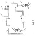
- cut tobacco 6 is delivered into the feeder 1, and then it is fed to a stream drier 2 via a mixing zone 0.
- the tobacco flows out of the device via a tobacco separator 3 and a feeder 1'.
- the process gas, particularly steam is recirculated by a recirculation pump 4 to a steam superheater 5.
- the process gas leaving the steam superheater 5 collects the dried material from the mixing zone 0.
- the process gas mixed with the dried substance, particularly steam flows into a stream drier 2.
- the dried material is removed from the system through the outlet 8 of the feeder 1'.
- Fig. 2 shows schematically a cross-sectional view of the feeder 1' mounted at the outlet of the stream drier 2.
- both feeders 1, 1' function as dosing-separating valves and due to their design and the principle of operation the noxious air is continuously flowing into the drier, which is denoted with the number 7 in Fig. 2 .
- the air introduced into the system increases the concentration of oxygen in the stream of the superheated steam, the latter being the process gas in this embodiment.
- a fresh portion of the process gas is introduced via the inlet 11.
- the whole amount of the process gas present in the circulation system of the drier is diluted, reducing the concentration of oxygen.
- the gas used for diluting the process gas, contaminated with oxygen as well as a waste of gas coming from the conduit of the drier, is removed via the outlet 9 and the release valve 10, and the outlet 9'.
- Fig. 2 shows schematically a cross-sectional view of the feeder 1' with denotation of individual flows of the agent according to the invention.
- the dried material which arrived at the feeder 1' from the stream drier 2, flows through its sections and is removed through the outlet 8.
- vanes of the feeder 1' rotate in the direction shown by the arrow 15.
- the excess of the process gas is removed through the outlet 9".
- Superheated steam from the interior of the drier, collected from the outlet 9 is introduced via the inlet 13 into the section of the feeder 1', emptied of the dried material, i.e., the section rotating towards the stream drier 2, the steam being next discharged via the outlet 14 as a process waste.
- a compact pump of a volumetric flow a little bit higher than the volume of water removed from the dried material in a form of vapor for given thermodynamic conditions, may be used to ensure the flow through the section of the feeder 1'.
- the process gas flowing through the section of the feeder 1' washes out the air with oxygen and causes removal of unnecessary amount of the process gas via the outlet 14 outside.
- the benefit of the invention is that the air in the section of the feeder 1' is significantly diluted. Significant reduction of entering the air, thus also oxygen, significantly, or even completely, eliminates the necessity of delivering clean superheated steam to the drier 2.
Landscapes
- Engineering & Computer Science (AREA)
- Mechanical Engineering (AREA)
- General Engineering & Computer Science (AREA)
- Drying Of Solid Materials (AREA)
- Manufacture Of Tobacco Products (AREA)
Abstract
Description
- This invention relates to a method of increasing the efficiency of a drier, particularly a stream drier, used for dry loose and flammable materials. The invention relates particularly to driers for cut tobacco, working with the use of a gaseous drying agent, particularly superheated steam.
- Many types of driers are known in the art, especially stream driers, working with a gaseous drying agent, in which superheated steam is used as a process gas of a temperature close or even higher than the ignition temperature of the dried material.
- Such conditions produce the necessity of removing oxidizing gases, particularly oxygen, entering the drier with the air. Oxygen contained in the air delivered into the drier may cause an explosion or fire, and also it is a reagent in chemical processes, which affects properties of the material. Due to their operation principle, dosing-separating valves, used so far, let the air (oxygen) into the drier, leading to disadvantageous changes in the composition of the process gas. Its regeneration needs significant expenditure of energy for the process of removing the oxygen from the whole volume of the process gas contained in the drier.
-
EP 0528227 A1 describes a method of drying tobacco material in a stream drier, in which, preferably, superheated steam is used as a drying agent. In the passage feeding the tobacco material to the drier a double rotary vane feeder is used, separating the stream drier from the surroundings and making it possible to feed the tobacco material to the drier. Another single feeder is located in the output conduit from the gas separator situated in the drier. - U.S. patent description No 4 791 942 discloses a design of a rotary vane feeder, as self-standing device for processing tobacco material, before feeding the material into another device. In the feeder housing there are openings leading to pressure chambers connected with conduits feeding superheated steam or carbon dioxide, as the process gas for processing the tobacco material, and with a conduit attached to the vacuum assembly.
- The subject matter of the invention is a method of increasing the efficiency of a drier, particularly a stream drier for loose or flammable materials, particularly cut tobacco, the drier working with a gaseous drying agent under a working pressure from 5 kPa to 10 MPa, measured as an absolute pressure.
- Preferably, superheated steam is used as the drying agent.
- According to the invention a pressurized process gas, preferably superheated steam, particularly coming from the interior of the drier, is passed through a dosing-separating valve, preferably a rotary vane feeder mounted behind the stream drier, particularly through its movable section with the dried material being emptied therefrom, the steam being returned from a release valve for reusing it in the process of diluting the air, the steam being regarded as a technology waste product.
- The method according to the invention is a continuous process and makes it possible to use in the drier a working pressure in the range from 5 kPa to 10 MPa, measured as an absolute pressure.
- The invention is illustrated by an embodiment shown in the accompanying drawings, in which:
-
Fig. 1 shows schematically a system for carrying out the method according to the invention, and -
Fig. 2 shows schematically a cross-sectional view of the feeder. - As shown in
Fig. 1 , cut tobacco 6 is delivered into thefeeder 1, and then it is fed to a stream drier 2 via a mixing zone 0. After drying, the tobacco flows out of the device via a tobacco separator 3 and a feeder 1'. The process gas, particularly steam, is recirculated by a recirculation pump 4 to a steam superheater 5. The process gas leaving the steam superheater 5 collects the dried material from the mixing zone 0. The process gas mixed with the dried substance, particularly steam, flows into a stream drier 2. The dried material is removed from the system through the outlet 8 of the feeder 1'. Behind the recirculation pump 4, considering the direction of the flow of the process gas denoted with thenumber 12, there are installed a release valve 10 with anoutlet 9, and still further aninlet 11 for entering fresh process gas free from the air, in order to reduce the air concentration in the process gas contaminated by the air circulating inside the drier. -
Fig. 2 shows schematically a cross-sectional view of the feeder 1' mounted at the outlet of the stream drier 2. It should be noted that in the inventive solution bothfeeders 1, 1' function as dosing-separating valves and due to their design and the principle of operation the noxious air is continuously flowing into the drier, which is denoted with the number 7 inFig. 2 . The air introduced into the system increases the concentration of oxygen in the stream of the superheated steam, the latter being the process gas in this embodiment. To reach the concentration of oxygen in the process gas, which is recommended for the drying process, usually below 4% by volume, a fresh portion of the process gas is introduced via theinlet 11. Using the fresh, i.e., free from the air, process gas, here the steam, the whole amount of the process gas present in the circulation system of the drier is diluted, reducing the concentration of oxygen. The gas used for diluting the process gas, contaminated with oxygen as well as a waste of gas coming from the conduit of the drier, is removed via theoutlet 9 and the release valve 10, and the outlet 9'. -
Fig. 2 shows schematically a cross-sectional view of the feeder 1' with denotation of individual flows of the agent according to the invention. The dried material, which arrived at the feeder 1' from the stream drier 2, flows through its sections and is removed through the outlet 8. As shown in the drawing, vanes of the feeder 1' rotate in the direction shown by thearrow 15. The excess of the process gas is removed through theoutlet 9". Superheated steam from the interior of the drier, collected from theoutlet 9, is introduced via theinlet 13 into the section of the feeder 1', emptied of the dried material, i.e., the section rotating towards the stream drier 2, the steam being next discharged via theoutlet 14 as a process waste. - Thus, a washer for the process gas is obtained in the feeder 1'. The air, which entered the feeder 1', due to the principle of operation of this device (denoted by the reference number 7), is subjected to significant dilution in this section of the feeder. Thus, the gas significantly washed from the air will enter the interior of the drier.
- A compact pump of a volumetric flow, a little bit higher than the volume of water removed from the dried material in a form of vapor for given thermodynamic conditions, may be used to ensure the flow through the section of the feeder 1'.
- The process gas flowing through the section of the feeder 1' washes out the air with oxygen and causes removal of unnecessary amount of the process gas via the
outlet 14 outside. - The benefit of the invention is that the air in the section of the feeder 1' is significantly diluted. Significant reduction of entering the air, thus also oxygen, significantly, or even completely, eliminates the necessity of delivering clean superheated steam to the drier 2.
Claims (1)
- method of increasing the efficiency of a drier, particularly a stream drier for loose and flammable materials, particularly cut tobacco, working with a gaseous drying agent under a working pressure from 5 kPa to 10 MPa, measured as an absolute pressure, preferably the drying agent being superheated steam, characterized in that a pressurized process gas, preferably waste steam, particularly coming from the interior of the drier, is passed through a dosing-separating valve, preferably a rotary vane feeder (1') mounted behind the stream drier (2), particularly through its movable section with the dried material being emptied therefrom, the steam being returned from a release valve (10) for reusing it in the process of diluting the air, the steam being regarded as a technology waste product.
Priority Applications (1)
| Application Number | Priority Date | Filing Date | Title |
|---|---|---|---|
| PL08156948T PL1997393T3 (en) | 2007-05-30 | 2008-05-27 | A method of increasing the efficiency of a dryer, especially a jet dryer |
Applications Claiming Priority (1)
| Application Number | Priority Date | Filing Date | Title |
|---|---|---|---|
| PL382542A PL211481B1 (en) | 2007-05-30 | 2007-05-30 | The manner of increase of efficiency of dryer, especially stream dryer |
Publications (3)
| Publication Number | Publication Date |
|---|---|
| EP1997393A2 true EP1997393A2 (en) | 2008-12-03 |
| EP1997393A3 EP1997393A3 (en) | 2009-05-13 |
| EP1997393B1 EP1997393B1 (en) | 2012-04-04 |
Family
ID=39714188
Family Applications (1)
| Application Number | Title | Priority Date | Filing Date |
|---|---|---|---|
| EP08156948A Not-in-force EP1997393B1 (en) | 2007-05-30 | 2008-05-27 | Method of increasing the efficiency of drier, particularly a stream drier |
Country Status (6)
| Country | Link |
|---|---|
| US (1) | US20080295355A1 (en) |
| EP (1) | EP1997393B1 (en) |
| JP (1) | JP5324132B2 (en) |
| CN (1) | CN101324396B (en) |
| AT (1) | ATE551914T1 (en) |
| PL (2) | PL211481B1 (en) |
Cited By (2)
| Publication number | Priority date | Publication date | Assignee | Title |
|---|---|---|---|---|
| EP2042045B1 (en) * | 2007-09-24 | 2012-12-05 | International Tobacco Machinery Poland Sp. z o.o. | Method and feeder for increasing efficiency of the expanding and drying process of organic plant materials, particularly in a jet drier and a feeder for use in the method |
| CN110286199A (en) * | 2019-06-17 | 2019-09-27 | 云南中烟工业有限责任公司 | A method for evaluating the consistency of processing strength of shredded shreds during drum drying based on the enthalpy of moisture evaporation in shredded shreds |
Families Citing this family (7)
| Publication number | Priority date | Publication date | Assignee | Title |
|---|---|---|---|---|
| DE102009028913A1 (en) * | 2009-08-26 | 2011-03-31 | Jt International S.A. | Apparatus and method for treating tobacco |
| CN102132950A (en) * | 2011-01-13 | 2011-07-27 | 中国烟草总公司郑州烟草研究院 | Process method for utilizing waste heat in tobacco shred airflow drying and special flow heating device |
| CN102183137B (en) * | 2011-03-02 | 2013-06-05 | 徐斌 | Digester, method for increasing evaporation dehydration efficiency of digester and inner member assembly for realizing method |
| GB201104311D0 (en) * | 2011-03-15 | 2011-04-27 | British American Tobacco Co | Method and apparatus for impregnating tobacco industry products with sensate constituents of botanicals |
| CN103591776A (en) * | 2013-11-25 | 2014-02-19 | 淮南市长安机电设备有限公司 | Waste heat drying equipment |
| CN104720094B (en) * | 2014-02-21 | 2016-02-24 | 安徽中烟工业有限责任公司 | A kind of tobacco online expansion and drying device of adopting carries out tobacco online expansion and dry method |
| CN114279202A (en) * | 2021-12-15 | 2022-04-05 | 河北白沙烟草有限责任公司保定卷烟厂 | Device for improving steam dryness |
Citations (2)
| Publication number | Priority date | Publication date | Assignee | Title |
|---|---|---|---|---|
| US4791942A (en) | 1986-08-01 | 1988-12-20 | The American Tobacco Company | Process and apparatus for the expansion of tobacco |
| EP0528227A1 (en) | 1991-08-19 | 1993-02-24 | Körber Ag | Device for introducing particles of tobacco in a drying stream |
Family Cites Families (10)
| Publication number | Priority date | Publication date | Assignee | Title |
|---|---|---|---|---|
| US4494556A (en) * | 1982-06-24 | 1985-01-22 | Brown & Williamson Tobacco Corporation | Pneumatic conveying tobacco drying apparatus |
| US4528995A (en) * | 1983-10-13 | 1985-07-16 | Brown & Williamson Tobacco Corporation | Sealed pneumatic tobacco conveying and treating apparatus |
| JP3109044B2 (en) * | 1990-11-07 | 2000-11-13 | 日本たばこ産業株式会社 | Air flow drying equipment for tobacco raw material expansion facilities |
| JP3140039B2 (en) * | 1990-11-07 | 2001-03-05 | 日本たばこ産業株式会社 | Flash drying method and apparatus for tobacco raw materials |
| CN1033206C (en) * | 1991-05-20 | 1996-11-06 | 日本烟草产业株式会社 | Expanding apparatus for agricultural product or like |
| AU644736B2 (en) * | 1991-05-20 | 1993-12-16 | Japan Tobacco Inc. | Expanding apparatus for agricultural product or the like |
| DE4117329A1 (en) * | 1991-05-27 | 1992-12-03 | Bat Cigarettenfab Gmbh | DRYING METHOD FOR INCREASING THE FILLABILITY OF TOBACCO MATERIAL AND DEVICE FOR IMPLEMENTING THIS METHOD |
| DE19909318C2 (en) * | 1999-03-03 | 2001-06-28 | Bat Cigarettenfab Gmbh | Method and device for expanding tobacco material |
| DE10038114A1 (en) * | 2000-08-04 | 2002-02-21 | Bat Cigarettenfab Gmbh | Method and device for conditioning shredded tobacco materials |
| JP3952470B2 (en) * | 2003-07-29 | 2007-08-01 | 金子農機株式会社 | Fluid dryer |
-
2007
- 2007-05-30 PL PL382542A patent/PL211481B1/en not_active IP Right Cessation
-
2008
- 2008-05-21 US US12/124,760 patent/US20080295355A1/en not_active Abandoned
- 2008-05-27 PL PL08156948T patent/PL1997393T3/en unknown
- 2008-05-27 AT AT08156948T patent/ATE551914T1/en active
- 2008-05-27 EP EP08156948A patent/EP1997393B1/en not_active Not-in-force
- 2008-05-30 CN CN200810131466XA patent/CN101324396B/en not_active Expired - Fee Related
- 2008-05-30 JP JP2008142874A patent/JP5324132B2/en not_active Expired - Fee Related
Patent Citations (2)
| Publication number | Priority date | Publication date | Assignee | Title |
|---|---|---|---|---|
| US4791942A (en) | 1986-08-01 | 1988-12-20 | The American Tobacco Company | Process and apparatus for the expansion of tobacco |
| EP0528227A1 (en) | 1991-08-19 | 1993-02-24 | Körber Ag | Device for introducing particles of tobacco in a drying stream |
Cited By (3)
| Publication number | Priority date | Publication date | Assignee | Title |
|---|---|---|---|---|
| EP2042045B1 (en) * | 2007-09-24 | 2012-12-05 | International Tobacco Machinery Poland Sp. z o.o. | Method and feeder for increasing efficiency of the expanding and drying process of organic plant materials, particularly in a jet drier and a feeder for use in the method |
| CN110286199A (en) * | 2019-06-17 | 2019-09-27 | 云南中烟工业有限责任公司 | A method for evaluating the consistency of processing strength of shredded shreds during drum drying based on the enthalpy of moisture evaporation in shredded shreds |
| CN110286199B (en) * | 2019-06-17 | 2021-09-21 | 云南中烟工业有限责任公司 | Method for evaluating consistency of cut tobacco processing strength in drum drying process based on cut tobacco moisture evaporation enthalpy |
Also Published As
| Publication number | Publication date |
|---|---|
| JP5324132B2 (en) | 2013-10-23 |
| ATE551914T1 (en) | 2012-04-15 |
| EP1997393A3 (en) | 2009-05-13 |
| CN101324396A (en) | 2008-12-17 |
| PL211481B1 (en) | 2012-05-31 |
| US20080295355A1 (en) | 2008-12-04 |
| PL382542A1 (en) | 2008-12-08 |
| EP1997393B1 (en) | 2012-04-04 |
| PL1997393T3 (en) | 2012-09-28 |
| JP2009060889A (en) | 2009-03-26 |
| CN101324396B (en) | 2011-04-13 |
Similar Documents
| Publication | Publication Date | Title |
|---|---|---|
| EP1997393B1 (en) | Method of increasing the efficiency of drier, particularly a stream drier | |
| JP6602871B2 (en) | Exhaust gas sampling system and method of operating such an exhaust gas sampling system | |
| US6713112B1 (en) | Meal cooler centrifugal separator | |
| JP2010504856A5 (en) | ||
| US20040020193A1 (en) | Method for cleaning a particular filter | |
| CN202973781U (en) | Cylinder dryer with hot air reverse flow operation | |
| CN100389853C (en) | A method of drying finely divided organic substances capable of producing explosive reactions | |
| WO2010019079A1 (en) | Method and system for treatment of malodorous gases emanating from a pulp mill | |
| CN105917509A (en) | Method for purging a fuel cell and device for carrying out the method | |
| JP3135519B2 (en) | Exhaust gas treatment equipment | |
| KR100988828B1 (en) | Sludge Mixing System | |
| CN108264209A (en) | Sludge dry system and method | |
| CN117781623A (en) | A steam drying device based on a copper smelting steam drying condensate recovery system | |
| CA2734371C (en) | Device for continuously conditioning fed-out natural gas | |
| KR101735801B1 (en) | Gas dehydrating apparatus and synthetic gas purifying apparatus having the same | |
| CN101209432A (en) | Furnace drying crusher | |
| CN115178092A (en) | Closed heating system | |
| RU2407582C2 (en) | Installation for gas dynamic drying of gas | |
| CN210320084U (en) | Flue gas treatment equipment | |
| CN111167283A (en) | Washing formula exhaust-gas treatment equipment | |
| CN109608001A (en) | Sludge drying system | |
| KR101242768B1 (en) | Blower | |
| CN214569207U (en) | Carbide slag storage equipment for cement production | |
| RU2306969C1 (en) | Cross-flow-through rotary dust-catcher | |
| CN109209592A (en) | A kind of large ship diesel-driven generator exhaust gas integrated treating device |
Legal Events
| Date | Code | Title | Description |
|---|---|---|---|
| PUAI | Public reference made under article 153(3) epc to a published international application that has entered the european phase |
Free format text: ORIGINAL CODE: 0009012 |
|
| AK | Designated contracting states |
Kind code of ref document: A2 Designated state(s): AT BE BG CH CY CZ DE DK EE ES FI FR GB GR HR HU IE IS IT LI LT LU LV MC MT NL NO PL PT RO SE SI SK TR |
|
| AX | Request for extension of the european patent |
Extension state: AL BA MK RS |
|
| PUAL | Search report despatched |
Free format text: ORIGINAL CODE: 0009013 |
|
| AK | Designated contracting states |
Kind code of ref document: A3 Designated state(s): AT BE BG CH CY CZ DE DK EE ES FI FR GB GR HR HU IE IS IT LI LT LU LV MC MT NL NO PL PT RO SE SI SK TR |
|
| AX | Request for extension of the european patent |
Extension state: AL BA MK RS |
|
| 17P | Request for examination filed |
Effective date: 20091113 |
|
| 17Q | First examination report despatched |
Effective date: 20091204 |
|
| AKX | Designation fees paid |
Designated state(s): AT BE BG CH CY CZ DE DK EE ES FI FR GB GR HR HU IE IS IT LI LT LU LV MC MT NL NO PL PT RO SE SI SK TR |
|
| GRAP | Despatch of communication of intention to grant a patent |
Free format text: ORIGINAL CODE: EPIDOSNIGR1 |
|
| RIN1 | Information on inventor provided before grant (corrected) |
Inventor name: SIEREDZINSKI, MAREK |
|
| GRAS | Grant fee paid |
Free format text: ORIGINAL CODE: EPIDOSNIGR3 |
|
| GRAA | (expected) grant |
Free format text: ORIGINAL CODE: 0009210 |
|
| AK | Designated contracting states |
Kind code of ref document: B1 Designated state(s): AT BE BG CH CY CZ DE DK EE ES FI FR GB GR HR HU IE IS IT LI LT LU LV MC MT NL NO PL PT RO SE SI SK TR |
|
| REG | Reference to a national code |
Ref country code: GB Ref legal event code: FG4D |
|
| REG | Reference to a national code |
Ref country code: CH Ref legal event code: EP |
|
| REG | Reference to a national code |
Ref country code: AT Ref legal event code: REF Ref document number: 551914 Country of ref document: AT Kind code of ref document: T Effective date: 20120415 |
|
| REG | Reference to a national code |
Ref country code: IE Ref legal event code: FG4D |
|
| REG | Reference to a national code |
Ref country code: CH Ref legal event code: NV Representative=s name: ARNOLD & SIEDSMA AG Ref country code: DE Ref legal event code: R096 Ref document number: 602008014577 Country of ref document: DE Effective date: 20120531 |
|
| REG | Reference to a national code |
Ref country code: NL Ref legal event code: VDEP Effective date: 20120404 |
|
| PGFP | Annual fee paid to national office [announced via postgrant information from national office to epo] |
Ref country code: DE Payment date: 20120418 Year of fee payment: 5 Ref country code: CH Payment date: 20120524 Year of fee payment: 5 |
|
| REG | Reference to a national code |
Ref country code: AT Ref legal event code: MK05 Ref document number: 551914 Country of ref document: AT Kind code of ref document: T Effective date: 20120404 |
|
| LTIE | Lt: invalidation of european patent or patent extension |
Effective date: 20120404 |
|
| REG | Reference to a national code |
Ref country code: PL Ref legal event code: T3 |
|
| PG25 | Lapsed in a contracting state [announced via postgrant information from national office to epo] |
Ref country code: LT Free format text: LAPSE BECAUSE OF FAILURE TO SUBMIT A TRANSLATION OF THE DESCRIPTION OR TO PAY THE FEE WITHIN THE PRESCRIBED TIME-LIMIT Effective date: 20120404 Ref country code: SE Free format text: LAPSE BECAUSE OF FAILURE TO SUBMIT A TRANSLATION OF THE DESCRIPTION OR TO PAY THE FEE WITHIN THE PRESCRIBED TIME-LIMIT Effective date: 20120404 Ref country code: NO Free format text: LAPSE BECAUSE OF FAILURE TO SUBMIT A TRANSLATION OF THE DESCRIPTION OR TO PAY THE FEE WITHIN THE PRESCRIBED TIME-LIMIT Effective date: 20120704 Ref country code: IS Free format text: LAPSE BECAUSE OF FAILURE TO SUBMIT A TRANSLATION OF THE DESCRIPTION OR TO PAY THE FEE WITHIN THE PRESCRIBED TIME-LIMIT Effective date: 20120804 Ref country code: SI Free format text: LAPSE BECAUSE OF FAILURE TO SUBMIT A TRANSLATION OF THE DESCRIPTION OR TO PAY THE FEE WITHIN THE PRESCRIBED TIME-LIMIT Effective date: 20120404 Ref country code: CY Free format text: LAPSE BECAUSE OF FAILURE TO SUBMIT A TRANSLATION OF THE DESCRIPTION OR TO PAY THE FEE WITHIN THE PRESCRIBED TIME-LIMIT Effective date: 20120404 Ref country code: FI Free format text: LAPSE BECAUSE OF FAILURE TO SUBMIT A TRANSLATION OF THE DESCRIPTION OR TO PAY THE FEE WITHIN THE PRESCRIBED TIME-LIMIT Effective date: 20120404 |
|
| PGFP | Annual fee paid to national office [announced via postgrant information from national office to epo] |
Ref country code: GB Payment date: 20120717 Year of fee payment: 5 |
|
| REG | Reference to a national code |
Ref country code: HU Ref legal event code: AG4A Ref document number: E014392 Country of ref document: HU |
|
| PG25 | Lapsed in a contracting state [announced via postgrant information from national office to epo] |
Ref country code: LV Free format text: LAPSE BECAUSE OF FAILURE TO SUBMIT A TRANSLATION OF THE DESCRIPTION OR TO PAY THE FEE WITHIN THE PRESCRIBED TIME-LIMIT Effective date: 20120404 Ref country code: PT Free format text: LAPSE BECAUSE OF FAILURE TO SUBMIT A TRANSLATION OF THE DESCRIPTION OR TO PAY THE FEE WITHIN THE PRESCRIBED TIME-LIMIT Effective date: 20120806 Ref country code: GR Free format text: LAPSE BECAUSE OF FAILURE TO SUBMIT A TRANSLATION OF THE DESCRIPTION OR TO PAY THE FEE WITHIN THE PRESCRIBED TIME-LIMIT Effective date: 20120705 Ref country code: HR Free format text: LAPSE BECAUSE OF FAILURE TO SUBMIT A TRANSLATION OF THE DESCRIPTION OR TO PAY THE FEE WITHIN THE PRESCRIBED TIME-LIMIT Effective date: 20120404 |
|
| PG25 | Lapsed in a contracting state [announced via postgrant information from national office to epo] |
Ref country code: BE Free format text: LAPSE BECAUSE OF FAILURE TO SUBMIT A TRANSLATION OF THE DESCRIPTION OR TO PAY THE FEE WITHIN THE PRESCRIBED TIME-LIMIT Effective date: 20120404 Ref country code: MC Free format text: LAPSE BECAUSE OF NON-PAYMENT OF DUE FEES Effective date: 20120531 |
|
| PGFP | Annual fee paid to national office [announced via postgrant information from national office to epo] |
Ref country code: IT Payment date: 20120529 Year of fee payment: 5 Ref country code: HU Payment date: 20120724 Year of fee payment: 5 |
|
| PG25 | Lapsed in a contracting state [announced via postgrant information from national office to epo] |
Ref country code: EE Free format text: LAPSE BECAUSE OF FAILURE TO SUBMIT A TRANSLATION OF THE DESCRIPTION OR TO PAY THE FEE WITHIN THE PRESCRIBED TIME-LIMIT Effective date: 20120404 Ref country code: AT Free format text: LAPSE BECAUSE OF FAILURE TO SUBMIT A TRANSLATION OF THE DESCRIPTION OR TO PAY THE FEE WITHIN THE PRESCRIBED TIME-LIMIT Effective date: 20120404 Ref country code: NL Free format text: LAPSE BECAUSE OF FAILURE TO SUBMIT A TRANSLATION OF THE DESCRIPTION OR TO PAY THE FEE WITHIN THE PRESCRIBED TIME-LIMIT Effective date: 20120404 Ref country code: RO Free format text: LAPSE BECAUSE OF FAILURE TO SUBMIT A TRANSLATION OF THE DESCRIPTION OR TO PAY THE FEE WITHIN THE PRESCRIBED TIME-LIMIT Effective date: 20120404 Ref country code: CZ Free format text: LAPSE BECAUSE OF FAILURE TO SUBMIT A TRANSLATION OF THE DESCRIPTION OR TO PAY THE FEE WITHIN THE PRESCRIBED TIME-LIMIT Effective date: 20120404 Ref country code: SK Free format text: LAPSE BECAUSE OF FAILURE TO SUBMIT A TRANSLATION OF THE DESCRIPTION OR TO PAY THE FEE WITHIN THE PRESCRIBED TIME-LIMIT Effective date: 20120404 Ref country code: DK Free format text: LAPSE BECAUSE OF FAILURE TO SUBMIT A TRANSLATION OF THE DESCRIPTION OR TO PAY THE FEE WITHIN THE PRESCRIBED TIME-LIMIT Effective date: 20120404 |
|
| PLBE | No opposition filed within time limit |
Free format text: ORIGINAL CODE: 0009261 |
|
| STAA | Information on the status of an ep patent application or granted ep patent |
Free format text: STATUS: NO OPPOSITION FILED WITHIN TIME LIMIT |
|
| REG | Reference to a national code |
Ref country code: IE Ref legal event code: MM4A |
|
| REG | Reference to a national code |
Ref country code: FR Ref legal event code: ST Effective date: 20130131 |
|
| 26N | No opposition filed |
Effective date: 20130107 |
|
| PG25 | Lapsed in a contracting state [announced via postgrant information from national office to epo] |
Ref country code: FR Free format text: LAPSE BECAUSE OF NON-PAYMENT OF DUE FEES Effective date: 20120604 Ref country code: IE Free format text: LAPSE BECAUSE OF NON-PAYMENT OF DUE FEES Effective date: 20120527 Ref country code: ES Free format text: LAPSE BECAUSE OF FAILURE TO SUBMIT A TRANSLATION OF THE DESCRIPTION OR TO PAY THE FEE WITHIN THE PRESCRIBED TIME-LIMIT Effective date: 20120715 |
|
| REG | Reference to a national code |
Ref country code: DE Ref legal event code: R097 Ref document number: 602008014577 Country of ref document: DE Effective date: 20130107 |
|
| PGFP | Annual fee paid to national office [announced via postgrant information from national office to epo] |
Ref country code: PL Payment date: 20130327 Year of fee payment: 6 |
|
| PG25 | Lapsed in a contracting state [announced via postgrant information from national office to epo] |
Ref country code: MT Free format text: LAPSE BECAUSE OF FAILURE TO SUBMIT A TRANSLATION OF THE DESCRIPTION OR TO PAY THE FEE WITHIN THE PRESCRIBED TIME-LIMIT Effective date: 20120404 Ref country code: BG Free format text: LAPSE BECAUSE OF NON-PAYMENT OF DUE FEES Effective date: 20121231 |
|
| PGFP | Annual fee paid to national office [announced via postgrant information from national office to epo] |
Ref country code: BG Payment date: 20130417 Year of fee payment: 6 |
|
| REG | Reference to a national code |
Ref country code: CH Ref legal event code: PL |
|
| GBPC | Gb: european patent ceased through non-payment of renewal fee |
Effective date: 20130527 |
|
| PG25 | Lapsed in a contracting state [announced via postgrant information from national office to epo] |
Ref country code: DE Free format text: LAPSE BECAUSE OF NON-PAYMENT OF DUE FEES Effective date: 20131203 Ref country code: CH Free format text: LAPSE BECAUSE OF NON-PAYMENT OF DUE FEES Effective date: 20130531 Ref country code: LI Free format text: LAPSE BECAUSE OF NON-PAYMENT OF DUE FEES Effective date: 20130531 |
|
| PG25 | Lapsed in a contracting state [announced via postgrant information from national office to epo] |
Ref country code: HU Free format text: LAPSE BECAUSE OF NON-PAYMENT OF DUE FEES Effective date: 20130528 Ref country code: IT Free format text: LAPSE BECAUSE OF NON-PAYMENT OF DUE FEES Effective date: 20130527 |
|
| REG | Reference to a national code |
Ref country code: DE Ref legal event code: R119 Ref document number: 602008014577 Country of ref document: DE Effective date: 20131203 |
|
| PG25 | Lapsed in a contracting state [announced via postgrant information from national office to epo] |
Ref country code: GB Free format text: LAPSE BECAUSE OF NON-PAYMENT OF DUE FEES Effective date: 20130527 Ref country code: TR Free format text: LAPSE BECAUSE OF FAILURE TO SUBMIT A TRANSLATION OF THE DESCRIPTION OR TO PAY THE FEE WITHIN THE PRESCRIBED TIME-LIMIT Effective date: 20120404 |
|
| PG25 | Lapsed in a contracting state [announced via postgrant information from national office to epo] |
Ref country code: LU Free format text: LAPSE BECAUSE OF NON-PAYMENT OF DUE FEES Effective date: 20120527 |
|
| PG25 | Lapsed in a contracting state [announced via postgrant information from national office to epo] |
Ref country code: BG Free format text: LAPSE BECAUSE OF NON-PAYMENT OF DUE FEES Effective date: 20141231 |
|
| PG25 | Lapsed in a contracting state [announced via postgrant information from national office to epo] |
Ref country code: PL Free format text: LAPSE BECAUSE OF NON-PAYMENT OF DUE FEES Effective date: 20140527 |
|
| REG | Reference to a national code |
Ref country code: PL Ref legal event code: LAPE |