EP1997366B1 - Agricultural harvester with a foreign object recognition device - Google Patents
Agricultural harvester with a foreign object recognition device Download PDFInfo
- Publication number
- EP1997366B1 EP1997366B1 EP08102560A EP08102560A EP1997366B1 EP 1997366 B1 EP1997366 B1 EP 1997366B1 EP 08102560 A EP08102560 A EP 08102560A EP 08102560 A EP08102560 A EP 08102560A EP 1997366 B1 EP1997366 B1 EP 1997366B1
- Authority
- EP
- European Patent Office
- Prior art keywords
- harvesting machine
- foreign body
- machine according
- agricultural harvesting
- crop
- Prior art date
- Legal status (The legal status is an assumption and is not a legal conclusion. Google has not performed a legal analysis and makes no representation as to the accuracy of the status listed.)
- Active
Links
- 238000004146 energy storage Methods 0.000 claims abstract description 27
- 238000012544 monitoring process Methods 0.000 claims abstract 2
- 238000003306 harvesting Methods 0.000 claims description 74
- 238000001514 detection method Methods 0.000 claims description 39
- 238000012546 transfer Methods 0.000 claims description 28
- 230000000694 effects Effects 0.000 claims description 18
- 239000000463 material Substances 0.000 claims description 14
- 239000002184 metal Substances 0.000 claims description 14
- 230000009467 reduction Effects 0.000 claims description 7
- 239000004575 stone Substances 0.000 claims description 4
- 239000000446 fuel Substances 0.000 claims description 3
- 230000002706 hydrostatic effect Effects 0.000 claims description 3
- 238000012545 processing Methods 0.000 claims description 3
- 230000011664 signaling Effects 0.000 claims 2
- 239000004459 forage Substances 0.000 description 13
- 230000006378 damage Effects 0.000 description 11
- 244000025254 Cannabis sativa Species 0.000 description 6
- 210000000056 organ Anatomy 0.000 description 6
- 240000008042 Zea mays Species 0.000 description 5
- 235000002017 Zea mays subsp mays Nutrition 0.000 description 5
- 230000035508 accumulation Effects 0.000 description 5
- 238000009825 accumulation Methods 0.000 description 5
- 238000000034 method Methods 0.000 description 5
- 230000008569 process Effects 0.000 description 5
- 239000002689 soil Substances 0.000 description 5
- 208000027418 Wounds and injury Diseases 0.000 description 4
- 235000005824 Zea mays ssp. parviglumis Nutrition 0.000 description 4
- 235000005822 corn Nutrition 0.000 description 4
- 208000014674 injury Diseases 0.000 description 4
- 238000011156 evaluation Methods 0.000 description 3
- 230000035484 reaction time Effects 0.000 description 3
- 241001124569 Lycaenidae Species 0.000 description 2
- 241001465754 Metazoa Species 0.000 description 2
- 230000001133 acceleration Effects 0.000 description 2
- 238000011161 development Methods 0.000 description 2
- 238000003825 pressing Methods 0.000 description 2
- 230000004044 response Effects 0.000 description 2
- 235000016383 Zea mays subsp huehuetenangensis Nutrition 0.000 description 1
- 235000013361 beverage Nutrition 0.000 description 1
- 230000008859 change Effects 0.000 description 1
- 238000005520 cutting process Methods 0.000 description 1
- 230000003111 delayed effect Effects 0.000 description 1
- 238000005286 illumination Methods 0.000 description 1
- 238000012423 maintenance Methods 0.000 description 1
- 235000009973 maize Nutrition 0.000 description 1
- 238000004513 sizing Methods 0.000 description 1
- 230000001960 triggered effect Effects 0.000 description 1
Images
Classifications
-
- A—HUMAN NECESSITIES
- A01—AGRICULTURE; FORESTRY; ANIMAL HUSBANDRY; HUNTING; TRAPPING; FISHING
- A01D—HARVESTING; MOWING
- A01D43/00—Mowers combined with apparatus performing additional operations while mowing
- A01D43/08—Mowers combined with apparatus performing additional operations while mowing with means for cutting up the mown crop, e.g. forage harvesters
- A01D43/086—Mowers combined with apparatus performing additional operations while mowing with means for cutting up the mown crop, e.g. forage harvesters and means for collecting, gathering or loading mown material
- A01D43/087—Mowers combined with apparatus performing additional operations while mowing with means for cutting up the mown crop, e.g. forage harvesters and means for collecting, gathering or loading mown material with controllable discharge spout
-
- A—HUMAN NECESSITIES
- A01—AGRICULTURE; FORESTRY; ANIMAL HUSBANDRY; HUNTING; TRAPPING; FISHING
- A01D—HARVESTING; MOWING
- A01D43/00—Mowers combined with apparatus performing additional operations while mowing
- A01D43/08—Mowers combined with apparatus performing additional operations while mowing with means for cutting up the mown crop, e.g. forage harvesters
- A01D43/085—Control or measuring arrangements specially adapted therefor
-
- A—HUMAN NECESSITIES
- A01—AGRICULTURE; FORESTRY; ANIMAL HUSBANDRY; HUNTING; TRAPPING; FISHING
- A01D—HARVESTING; MOWING
- A01D75/00—Accessories for harvesters or mowers
- A01D75/18—Safety devices for parts of the machines
- A01D75/187—Removing foreign objects
Definitions
- the invention relates to an agricultural harvester with a collection device for forwarding harvested crop to subsequent processing units, wherein the collection device is provided with a foreign body detection device for detecting foreign bodies in the crop stream and with means for immediate stopping of the feeders upon detection of a foreign body in the crop.
- Feeder devices in the form of harvesting attachment devices with foreign object detection devices are generally used in agricultural harvesting machines, in particular in forage harvesters, in order to transport, possibly together with the crop material, into the machine - e.g. to recognize a turning tines, pasture fence, beverage can or a nail and automatically switch off the feeder and subsequent processing organs in this case. This is to prevent the metal parts from causing damage within the agricultural harvester or from being later ingested by the animals when feeding the harvested crop and resulting in dislocation or even death of animals.
- a feeder consists of one or more feed roller pairs connected in series, crop picked up by a header of the harvester is pulled in by the rollers and fed, for example, to a subsequent chopper drum or other working aggregate
- Such a foreign object recognition device is known from DD 247 117 A3 in which a metal detector is arranged in a conveyor roller which cooperates with a conveyor roller.
- the metal detector is usually mounted stationary within one of the front feed rollers,
- the detection range of the metal detector is of
- the measuring magnetic field is preferably oriented approximately vertically from below into the Erntegutstrom or often obliquely forward, in the direction of the header, the measured detector signal is constantly measured and with a predefined Threshold compared, which when it exceeds a shutdown signal is given to the conveyor,
- Such a foreign body detection device is from the DD-PS 247 118
- a stop signal is triggered which is fed to the stop device of the conveyor elements.
- EP-A-1523876 discloses a harvester with a metal detection device that provides a stop signal to a quick stop circuit, thereby immediately stopping the entire harvester.
- the invention is therefore based on the object to avoid the disadvantages of the cited prior art and to further develop a foreign object detecting device having agricultural harvester of the type mentioned above, that, when a foreign object is detected by the foreign body detection device, it is possible to avoid as much as possible accumulation of crop material or its overrunning and depression,
- the at least one energy storage medium is the fuel for operating the drive motor and / or the oil for operating a hydrostatic drive of the agricultural harvesting machine,
- the value for the braking effect and / or for the withdrawal of the at least one energy storage medium is adjustable so that, for example, at a high harvesting operating speed abrupt stopping, quasi A full braking of the agricultural harvester is avoided in order to protect the usually not vorgewarnten operator of the harvester from injury.
- the setting of the values for the braking effect and / or for the reduction of the travel speed is carried out according to the slope of the crop field, so that too abrupt stopping of the harvester and thus coming into contact of the header of the harvester with the field soil avoidable, especially in a downhill and thus damage to the crop and the harvesting attachment can be prevented.
- the harvesting speed of the harvesting machine can advantageously also be taken into account when setting the value for the braking effect and / or for the withdrawal of the at least one energy sizing medium, which influence the deceleration of the harvesting machine.
- the threshold values can be set manually, so that the operator has the opportunity to control the setting of the value for the braking effect and / or for the withdrawal of the at least one energy storage medium in his discretion, It is also beyond It is conceivable that the threshold values of the corresponding Erntebetnebsparameter be detected automatically via corresponding sensors, so that the driver is released from a control and can focus on the harvesting operation alone.
- the deceleration and / or the withdrawal of the at least one energy storage medium to reduce the speed of the harvesting machine as a function of the speed setpoint predetermined by the throttle lever the operator can thus better get in that in the event of foreign body detection of Braking occurs as if it were returning the drive lever from the currently selected vehicle speed position to the zero position, thus avoiding a potential risk of injury to the operator,
- the return of the travel speed is signaled by means of at least one signal means, preferably acoustically and / or optically, so as to ensure that the operator of the harvesting machine itself or the operators of other vehicles recognize it a foreign body in the crop flow are informed.
- the signal means is the brake device the harvester
- the transfer device upon detecting a foreign body in the crop stream, the transfer device is pivoted in the direction of travel when the transfer device is in a lateral transfer position, the pivoting of the transfer device relative to the value for the braking effect and / or for the withdrawal of the energy storage medium to reduce the travel speed of the harvesting machine is completed. This ensures that in the harvesting operation during the reloading of crop on a vehicle next to it no crop loss occurs when the vehicle next to it does not initiate the braking process at the same time and with the same effect as the harvester, but then partially ahead of the harvester.
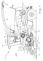
- FIG. 1 showed an agricultural harvester 1 in the form of a forage harvester 2.
- a forage harvester 2 designed as a pickup 3 Emtevorsatz réelle 4 is arranged.
- the crop 5 is picked up from the field soil 6 and fed to the downstream work organs 7, the several meters wide header 4 performs the recorded crop 5 in a much narrower, the width of the conveyor channel 8 corresponding catchment area 9 together.
- the crop 5 is assumed by a first Vorpresswalzenplo 10 and compacted.
- the crop 5 is cut by the chopping blades 13 and accelerated by the chopper drum 14 downstream Vietnamese beschreiber 15 and promoted via a subsequent transfer device 16 from the forage harvester 2 and thereby, for example, a transport vehicle not shown here overloaded.
- the traction drive of the harvester 1 via a central drive motor 17. About a drive shaft, not shown
- the drive speed is controlled by a known not-shown driving lever, which may be designed as a hand lever or foot pedal and is arranged in the cab 19.
- a foreign body recognition device 20 in the form of a metal detector device 21 is arranged inside the lower prepressing roller of the first prepressing roller pair 10, with which metallic parts 22 can be sensed in the crop stream. It is also conceivable that the foreign body detection device 20 is designed as a stone detector.
- the structure and function of a known metal detection device 21 is closer in the DE 10 2005 005 736 A1
- the metal detection device 21 operates for this purpose with a magnetic measuring field M, which is aligned upward in the Erntegutstrom so that the crop 5 passes through this magnetic field M, metal part 22 lead to a change in the measuring Magnetic field M, which are detected by the metal detection device 23,
- These changes of the magnetic field M are transmitted to a signal module not shown in detail, which generates depending on the voltage changes, detection signals S, which are transmitted to a signal evaluation device 23, the signal evaluation device 23 in turn connected with a per se known and therefore not shown Schnellstopvorrichturig, which then ensures an immediate stop of the pre-press rollers 10,11 and the header 4.
- the operator 24 triggers a reversing process in which the jointly driven pre-press rolls 10, 11 and the header 4 are driven in the reverse direction.
- the invention is based, which provides that when a foreign body in the crop stream is detected by the foreign body recognition device 20, the at least one energy storage medium is automatically decelerated and / or taken back to reduce the travel speed of the harvester 1, in order to accumulate crop material 5 For example, deposited in swaths of grass or a driving over and pressing down on the crop to be harvested 5, such as corn to avoid.
- the fuel for operating the drive motor 17 which provides the drive power for the traction drive available and / or the oil to operate a hydrostatic traction drive, preferably is the value adjustable for the braking effect and / or for the withdrawal of the energy storage medium, so that can always be selected by the possibility of variable adjustment, the situation or harvest conditionally optimal setting.
- the foreign body detection device 20 is connected to a control unit 25 for controlling the braking effect of the known braking device and not shown here and / or for controlling the withdrawal of the energy storage medium in the form of a driving lever not shown here for reducing the speed of the harvester 1.
- the detection signal S is transferred to the control unit 25 and stored in the control unit 25.
- the controller 25 is also connected to an adjuster 26 and the quick stop device.
- the adjusting device 26 controls the setting of the value of the braking effect and / or the value of the withdrawal of the energy storage medium to reduce the driving speed of the harvester 1 in the event of a FremdMecherkenrurig, Basically, it is provided that the deceleration and / or the withdrawal of the energy storage medium to reduce the driving speed the harvester 1 is done until the standstill of the harvester 1 is reached. However, it is also conceivable that a freely definable travel speed range is not undershot.
- threshold values as a function of harvesting operating parameters are used as the basis for setting the values for the braking effect and / or for the withdrawal of the energy storage medium in the event of foreign body detection be entered.
- the thresholds are determinable by the operator 24 and may be changed at his discretion become.
- the crop type, the driving speed of the agricultural harvesting machine 1 per se or the slope of the crop field are considered as harvesting parameters, so that a relief of the operator of the agricultural harvesting machine 1 can be achieved by setting the threshold values of the crop
- the Erntegutart different speeds such as a higher travel speed in the grass harvester compared to a lower in the corn harvest, with a higher travel speed basically a lower value is set to an abrupt stopping of the harvester 1 from To avoid a higher travel speed, which would sometimes cause significant injury to the operator 24.
- the adjustment device 26 can be designed such that the threshold values of the crop parameters are manually input by the operator 24 from the driver's cab 19 via a control panel 27. It is also conceivable that the threshold values of the harvesting operating parameters are detected automatically via corresponding sensors (not shown here) so that the operator 24 is released from controlling the harvesting parameters and can focus solely on the harvesting operation. In addition, it is provided that the adjustment of the values for the braking effect and / or for the withdrawal of the energy storage medium to reduce the driving speed corresponding to the slope of the Emtefeldes, so that especially in a downhill too abrupt stopping the harvester 1 and thus in contact come of the header 4 of the harvester 1 with the field soil 6 is avoidable and thus damage to the crop and the crop attachment 4 can be prevented.
- the harvesting speed of the harvesting machine 1, as well as the weight of the header 4 can be taken into account when setting the value for the braking effect and / or for the withdrawal of the energy storage medium per se advantageously, especially in very large and heavy header 4, a to prevent extreme forward tipping, as a result of abrupt stopping of the harvester 1, to avoid damage to the header 4.
- the setting of the value for the braking effect and / or for the retraction of the ground speed can be made according to the slope of the crop field, so that, in particular, when driving downhill also too abrupt stopping the harvester 1 and thus come into contact with the header attachment 4 of the harvester with the field soil 6 is avoidable, thus preventing damage to the crop and the harvesting attachment 4.
- the deceleration and / or the withdrawal of the energy storage medium for reducing the travel speed of the harvester 1 in response to the speed setpoint predetermined by the control lever in response to the speed setpoint predetermined by the control lever.
- the control unit 25 automatically actuates the foot brake in the event of foreign object recognition by means not described here, so that the braking of the harvesting machine 1 can be achieved in a simple manner and thus the damming of the crop 5 can be avoided.
- the return of the travel speed can be signaled acoustically and / or optically by means of at least one signal means 29 configured here as brake light device 28, so that operators are warned by the harvesting machine 1 following vehicles about the illumination of the brake light device 28, so as to be able to initiate a braking process in good time, in order to avoid a collision with the harvesting machine.
- the transfer of the header 4 from the ground near working and operating position in an at least partially raised headland position reversing the drive movement of the working elements 7, so that already existing in the working organs 7 crop 5 is eliminated by reversing and the operator 24 without additional Loss of time can resume the harvesting operation.
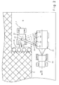
- a forage harvester 2 is shown in plan view, front side of the forage harvester is a header 4, in this case a maize header 30 assigned, which cuts the crop 5, receives and feeds a not shown chopping device.
- the comminuted crop 5 is then transferred via a transfer device 16 to a transport device 31.
- the transport device 31 is adapted to a tractor 32, which in the ideal case runs parallel next to or, as not shown here, directly behind the forage harvester 2.
- the transfer device 16 arranged behind the driver's cab 19 can be pivoted about a vertical axis of rotation 33 and about a horizontal axis 34 for changing the height adjustment.
- the width of the ejected Erntegutstrahls be controlled by an up and lowerable Mechanism 35, If theSubnadeklappe 35 pivoted upward, the Erntegutstrahl continues, the Sprintladeklappe 35 is pivoted downward, the Erntegutstrahl is thrown less far.
- the operator 24 of an agricultural harvesting machine 1 faces the problem that the harvester 1 is decelerated in the event of foreign body harvesting, but at the same time crop material 5 is still being ejected via the transfer device 16.
- the operator of the adjacent transport device 31 will not start the braking process at the same time as the harvesting machine 1, so that it will give up its ideal position and the harvester 1 will precede, and then that the crop 5 still to be overloaded will not impact the transport device 31 but rather behind the transport device 31 is thrown onto the field floor 6.
- the transfer device 16 when the transfer device 16 occupies a lateral transfer position X1-X4 and a foreign body recognition is present, the transfer device 16 is pivoted in the direction of travel FR, so that the transfer device 16 vorseilenden the transport vehicle 32, lags to the remaining, located in the harvester 1 crop 5 on the transport device 31 to throw over, preferably carried out the pivoting of the transfer device 16 in the same proportion as the braking and / or the withdrawal of the speed of the Harvesting machine 1 is detected when detecting a foreign body in the crop, so that a possible maintenance of the impact point of the Erntegutstrahls not shown on the Transportvornchtung 31 is reached.
- the transport device 31 In the event that the transport device 31 is located behind the harvester 1 and the transfer device 16 occupies a rearward position, not shown, takes place when detecting a foreign body by the foreign body detection device 20, the deceleration or the withdrawal of the travel speed of the harvester 1 in time after the foreign body detection So that operators of the harvester 1 subsequent transport vehicles 32 even early initiate a braking operation and can avoid a collision with de harvester 1.
Landscapes
- Life Sciences & Earth Sciences (AREA)
- Environmental Sciences (AREA)
- Harvester Elements (AREA)
- Combines (AREA)
- Harvesting Machines For Root Crops (AREA)
- Geophysics And Detection Of Objects (AREA)
Abstract
Description
Die Erfindung betrifft eine landwirtschaftliche Erntemaschine mit einer Einzugsvorrichtung zur Weiterleitung von geerntetem Erntegut zu nachfolgenden Bearbeitungsaggregaten, wobei die Einzugsvorrichtung mit einer Fremdkörpererkennungsvorrichtung zum Erkennen von Fremdkörpern im Erntegutstrom und mit Einrichtungen zum unmittelbaren Stoppen der Zuführeinrichtungen bei Feststellung eines Fremdkörpers im Erntegut versehen ist.The invention relates to an agricultural harvester with a collection device for forwarding harvested crop to subsequent processing units, wherein the collection device is provided with a foreign body detection device for detecting foreign bodies in the crop stream and with means for immediate stopping of the feeders upon detection of a foreign body in the crop.
Zuführeinrichtungen in Form von Erntevorsatzgeräten mit Fremdkörpererkennungseinrichtungen werden in der Regel in landwirtschaftlichen Erntemaschinen, insbesondere in Feldhäckslern, eingesetzt, um eventuell gemeinsam mit dem Erntegut in die Maschine eingedrungene Meiai!körper - z.B. einen Wenderzinken, Weidezaunpfahl, Getränkedose oder einen Nagel zu erkennen und in diesem Fall die Zuführeinrichtung und nachfolgende Bearbeitungsorgane automatisch abzuschalten. Dadurch soll verhindert werden, dass die Metallteile Schäden innerhalb der landwirtschaftlichen Erntemaschine verursachen oder später beim Verfüttern des geernteten Erntegutes von den Tieren aufgenommen werden und zu Versetzungen oder sogar zum Tod von Tieren führen kann. Bei einem typischen Aufbau besteht eine solche Zuführeinrichtung aus einem oder mehreren hintereinander geschalteten Einzugswalzenpaaren, Erntegut, das von einem Erntevorsatzgerät der Erntemaschine aufgenommen wird, wird von den Walzen eingezogen und beispielsweise einer nachfolgenden Häckseltrommel oder einem anderen Arbeitsaggregat zugeleitetFeeder devices in the form of harvesting attachment devices with foreign object detection devices are generally used in agricultural harvesting machines, in particular in forage harvesters, in order to transport, possibly together with the crop material, into the machine - e.g. to recognize a turning tines, pasture fence, beverage can or a nail and automatically switch off the feeder and subsequent processing organs in this case. This is to prevent the metal parts from causing damage within the agricultural harvester or from being later ingested by the animals when feeding the harvested crop and resulting in dislocation or even death of animals. In a typical structure, such a feeder consists of one or more feed roller pairs connected in series, crop picked up by a header of the harvester is pulled in by the rollers and fed, for example, to a subsequent chopper drum or other working aggregate
Eine solche Fremdkörpererkennungseinrichtung ist aus der
Im weiteren sind Fremdkörpererkennungseinrichtungen in Form von Steindetektoren bekannt, die die Arbeitsaggregate vor der Beschädigung durch Steine, die mit dem Erntegut zugeführt werden, sichern sollen, Eine derartige Fremdkörpererkennungseinrichtung ist aus der
Nachteilig an den bekannten Fremdkörpererkennungsvorrichtungen und deren Nutzung in landwirtschaftlichen Erntemaschinen ist jedoch, dass die landwirtschaftliche Erntemaschine aufgrund des Stoppens sämtlicher Arbeitsorgane kein Erntegut mehr aufnehmen kann. Da vom Auslösen der Fremdkorpererkennungseinnchtung bis zum Stoppen der Erntemaschine, aufgrund der Reaktionszeit des Bedieners, eine gewisse Zeitspanne vergeht, kann es zu Aufstauungen von Erntegut kommen. Insbesondere ein Feldhäcksler in der Grasernte fährt hohe Erntegeschwindigkeiten, so dass dieser im Falle der Fremdkörpererkennung z.T, riesige Schwaden Gras vor sich herschiebt, bevor der Feldhäcksler zum Stillstand kommt. Wenn diese Anhäufungen des Erntegutes nach Beseitigung des Fremdkörpers dann von der Erntemaschine aufgenommen werden müssen, führt dies häufig zu Überlastungen der Erntemaschine, die zu Schäden führen können, im Fall, dass es sich um noch abzuerntendes Erntegut, wie Mais, handelt, kommt es dann zu dessen Überfahren und Niederdrücken, welches bei häufigen Ansprechen der Fremdkörpererkennungseinrichtung zu nicht vernachlässigbaren Erntegutverlusten führen kann.A disadvantage of the known foreign body detection devices and their use in agricultural harvesters, however, is that the agricultural harvester can no longer receive crop due to the stopping of all working organs. Since a certain amount of time passes from the triggering of the foreign body recognition device until the stopping of the harvester, due to the reaction time of the operator, accumulation of crop material can occur. In particular, a forage harvester in the grass harvester drives high harvesting speeds, so that in the case of foreign body recognition, for example, huge swaths push grass in front of them before the forage harvester comes to a standstill. If these accumulations of crop after removal of the foreign body then have to be absorbed by the harvester, this often leads to overloading of the harvester, which can lead to damage, in the case that it is still harvesting crop, such as corn, it is for its overrunning and depression, which can result in frequent response of the foreign body detection device to non-negligible crop losses.
Der Erfindung liegt deshalb die Aufgabe zugrunde, die Nachteile des zitierten Standes der Technik zu vermeiden und eine eine Fremdkörpererkennungsvorrichtung aufweisende landwirtschaftliche Erntemaschine der eingangs genannten Art derart weiterzuenwckeln, dass beim Erkennen eines Fremdkörpers durch die Fremdkörpererkennungseinrichtung möglichst Aufstauungen von Erntegut bzw. dessen Überfahren und Niederdrücken vermieden werden,The invention is therefore based on the object to avoid the disadvantages of the cited prior art and to further develop a foreign object detecting device having agricultural harvester of the type mentioned above, that, when a foreign object is detected by the foreign body detection device, it is possible to avoid as much as possible accumulation of crop material or its overrunning and depression,
Diese Aufgabe wird erfindungsgemäß durch die kennzeichnenden Merkmale der Patentanspruchs 1 gelöst, wobei in den weiteren Patentansprüchen Merkmale aufgeführt sind, die diese Lösung in vorteilhafter Weise weiterentwickeln.This object is achieved by the characterizing features of claim 1, which are listed in the other claims features that further develop this solution in an advantageous manner.
Indem beim Erkennen eines Fremdkörpers im Erntegutstrom durch die Fremdkörpererkennungsvornchtung die Erntemaschine automatisch abgebremst und/oder die Rücknahme des wenigstens einen Energiespeichermediums zur Reduzierung der Fahrgeschwindigkeit der landwirtschaftlichen Erntemaschine erfolgt, ist sichergestellt, dass weitestgehend ein Aufstauen von Erntegut, wie z.B, in Schwaden abgelegtes Gras bzw, ein Überfahren und Niederdrücken des noch zu erntenden Erntegutes, wie z.B. Mais vermieden wird. Dabei ist der Wert für die Bremswirkung und/oder für die Rücknahme der Fahrgeschwindigkeit einstellbar, so dass durch die Möglichkeit der variablen Einstellung, stets die situations- bzw. erntebedingt optimale Einstellung gewählt werden kann. Vorzugsweise ist das wenigstens eine Energiespeichermedium der Kraftstoff zum Betreiben des Antriebsmotors und/oder das Öl zum Betreiben eines hydrostatischen Fahrantriebes der landwirtschaftlichen Erntmaschine,By automatically decelerating the harvesting machine and / or taking back the at least one energy storage medium to reduce the driving speed of the agricultural harvesting machine upon detection of a foreign body in Erntegutstrom by the Fremdkörpererkennungsmeitiums, it is ensured that as far as possible a damming of crops, such as stored in swaths of grass or , a driving over and pressing down on the harvested crop, such as Corn is avoided. In this case, the value for the braking effect and / or for the withdrawal of the driving speed is adjustable, so that the possibility of variable setting, always the situation or harvest-related optimal setting can be selected. Preferably, the at least one energy storage medium is the fuel for operating the drive motor and / or the oil for operating a hydrostatic drive of the agricultural harvesting machine,
Dadurch, dass das Abbremsen und/oder die Rücknahme des wenigstens einen Energiespeichermediums zur Reduzierung der Fahrtgeschwindigkeit der Erntemaschine zum Erreichen des Stillstandes der Erntemaschine bei einer Fremdkörpererkennung in Abhängigkeit von mindestens einem Schwellwert, wie die Erntegutart, die Fahrgeschwindigkeit der landwirtschaftlichen Erntemaschine oder die Hangneigung des Erntefeldes einstellbar ist, erfolgt vorteilhaft eine Entlastung für den Bediener der Erntemaschine. Insbesondere erfolgt in Abhängigkeit von der Erntegutart der Erntebetrieb mit unterschiedlichen Erntegeschwindigkeiten, wobei dann entsprechend im Falle einer Fremdkörpererkennung der Wert für die Bremswirkung und/oder für die Rücknahme des wenigstens einen Energiespeichermediums so einstellbar ist, dass beispielhaft bei einer hohen Erntebetriebsgeschwindigkeit ein abruptes Abstoppen, quasi eine Vollbremsung der landwirtschaftlichen Erntemaschine vermieden wird, um den in der Regel nicht vorgewarnten Bediener der Erntemaschine vor Verletzungen zu schützen, Zudem ist vorteilhaft, dass die Einstellung der Werte für die Bremswirkung und/oder für die Rücknahme der Fahrtgeschwindigkeit entsprechend der Hangneigung des Erntefeldes erfolgt, so dass insbesondere bei einer Bergabfahrt gleichfalls ein zu abruptes Stoppen der Erntemaschine und damit ein in Kontakt kommen des Erntevorsatzgerätes der Erntemaschine mit dem Feldboden vermeidbar ist und somit Schäden an der Erntepflanze und dem Erntvorsatzgerät verhindert werden können. Im Weiteren können vorteilhaft auch per se die Erntegeschwindigkeit der Erntemaschine, wie auch das Gewicht des Erntevorsatzgerätes bei der Einstellung des Wertes für die Bremswirkung und/oder für die Rücknahme des wenigstens einen Energsespetchermediums Berücksichtigung finden, die das Abbremsen der Erntemaschine beeinflussen.Characterized in that the deceleration and / or the withdrawal of the at least one energy storage medium for reducing the travel speed of the harvester for reaching the standstill of the harvester at a foreign body detection in dependence on at least one threshold, such as Erntegutart, the driving speed of the agricultural harvester or the slope of the crop field is adjustable, advantageously takes a relief for the operator of the harvester. In particular, depending on the Erntegutart the harvesting operation with different harvesting speeds, in which case in the event of foreign body detection, the value for the braking effect and / or for the withdrawal of the at least one energy storage medium is adjustable so that, for example, at a high harvesting operating speed abrupt stopping, quasi A full braking of the agricultural harvester is avoided in order to protect the usually not vorgewarnten operator of the harvester from injury, In addition, it is advantageous that the setting of the values for the braking effect and / or for the reduction of the travel speed is carried out according to the slope of the crop field, so that too abrupt stopping of the harvester and thus coming into contact of the header of the harvester with the field soil avoidable, especially in a downhill and thus damage to the crop and the harvesting attachment can be prevented. Furthermore, the harvesting speed of the harvesting machine, as well as the weight of the harvesting attachment, can advantageously also be taken into account when setting the value for the braking effect and / or for the withdrawal of the at least one energy sizing medium, which influence the deceleration of the harvesting machine.
In einer vorteilhaften Weiterbildung der Erfindung können die Schwellwerte manuell festgelegt werden, so dass der Bediener die Möglichkeit hat, die Einstellung des Wertes für die Bremswirkung und/oder für die Rücknahme des wenigstens einen Energiespeichermediums nach seinem Ermessen steuern zu können, Es ist darüber hinaus auch denkbar, dass die Schwellwerte der entsprechenden Erntebetnebsparameter über entsprechende Sensoren selbsttätig erfasst werden, so dass der Fahrer von einer Kontrolle entbunden wird und sich allein auf den Erntebetrieb konzentrieren kann.In an advantageous embodiment of the invention, the threshold values can be set manually, so that the operator has the opportunity to control the setting of the value for the braking effect and / or for the withdrawal of the at least one energy storage medium in his discretion, It is also beyond It is conceivable that the threshold values of the corresponding Erntebetnebsparameter be detected automatically via corresponding sensors, so that the driver is released from a control and can focus on the harvesting operation alone.
Bei einem besonders bevorzugten Ausführungsbeispiel erfolgt das Abbremsen und/oder die Rücknahme des wenigstens einen Energiespeichermediums zur Reduzierung der Fahrtgeschwsndigkeit der Erntemaschine in Abhängigkeit vom über den vom Fahrhebel vorgegebenen Geschwindigkeits-Sollwert, Der Bediener kann sich somit besser darauf einsteigen, dass im Falle einer Fremdkörpererkennung der Bremsvorgang so erfolgt, als wenn er den Fahrhebel von der aktuell gewählten Fahrtgeschwindigkeitsposition in die Nullposition zurückführen würde, so dass eine potentielle Verletzungsgefahr für den Bediener vermieden wird,In a particularly preferred embodiment, the deceleration and / or the withdrawal of the at least one energy storage medium to reduce the speed of the harvesting machine as a function of the speed setpoint predetermined by the throttle lever, the operator can thus better get in that in the event of foreign body detection of Braking occurs as if it were returning the drive lever from the currently selected vehicle speed position to the zero position, thus avoiding a potential risk of injury to the operator,
In einer weiteren vorteilhaften Weiterbildung der Erfindung wird beim Erkennen eines Fremdkörpers im Erntegutstrom die Rücknahme der Fahrtgeschwindigkeit mittels wenigstens eines Signalmittels, vorzugsweise akustisch und/oder optisch, signalisiert, so dass sichergestellt ist, dass der Bediener der Erntemaschine selbst oder Bediener anderer Fahrzeuge über das Erkennen eines Fremdkörpers im Erntegutstrom informiert sind.In a further advantageous development of the invention, when a foreign body is detected in the crop stream, the return of the travel speed is signaled by means of at least one signal means, preferably acoustically and / or optically, so as to ensure that the operator of the harvesting machine itself or the operators of other vehicles recognize it a foreign body in the crop flow are informed.
Damit sichergestellt ist, dass ein der Erntemaschine nachfolgendes Fahrzeug über die Erkennung eines Fremdkörpers im Erntegutstrom der Erntemaschine informiert ist und selbst rechtzeitig einen Bremsvorgang, zur Vermeidung einer Kollision mit der vorausfahrenden Erntemaschine, einleiten kann, ist in einer vorteilhaften Ausgestaltung der Erfindung das Signalmittel die Bremsiichteinrichiung der Erntemaschine,In order to ensure that a vehicle following the harvesting machine is informed about the recognition of a foreign body in the crop stream of the harvester and can initiate a braking process in time to avoid a collision with the preceding harvester, in an advantageous embodiment of the invention the signal means is the brake device the harvester,
Indem das Abbremsen und/oder die Rücknahme des Energiespeichermediums zeitlich nach dem Erkennen eines Fremdkörpers im Erntegutstrom erfolgt, wenn sich die Überiadeeinrichtung in einer rückwärtigen Überladeposition befindet, ist sichergestellt, dass den Bedienern der Erntemaschine nachfolgenden Fahrzeuge genügend Reaktionszeit verbleibt, um selbst einen Bremsvorgang bzw. ein Ausgleichmanöver zu starten, um eine Kollision mit der vorausfahrenden Erntemaschine zu verhindern.By the braking and / or the withdrawal of the energy storage medium takes place in time after the recognition of a foreign body in the Erntegutstrom when the Überiadeeinrichtung is in a rear Überladeposition, it is ensured that the operators of the harvester subsequent vehicles sufficient reaction time remains to themselves a braking operation or to start a balancing maneuver to prevent a collision with the preceding harvester.
In einer vorteilhaften Weiterentwicklung der Erfindung erfolgt beim Erkennen eines Fremdkörpers im Erntegutstrom ein Verschwenken der Überladeeinrichtung in Fahrtrichtung, wenn sich die Überladeeinrichtung in einer seitlichen Überladeposition befindet, wobei das Verschwenken der Überladeeinrichtung im Verhältnis zum Wert für die Bremswirkung und/oder für die Rücknahme des Energiespeichermediums zur Reduzierung der Fahrtgeschwindigkeit der Erntmaschine vollzogen wird. Damit ist sichergestellt, dass im Erntebetrieb während des Überladevorgangs von Erntegut auf ein nebenherfahrendes Fahrzeug kein Erntgutverlust eintritt, wenn das nebenherfahrende Fahrzeug nicht zeitgleich und mit gleicher Wirkung wie die Erntemaschine den Bremsvorgang einleitet, sondern der Erntemaschine dann teilweise vorauseilt.In an advantageous further development of the invention, upon detecting a foreign body in the crop stream, the transfer device is pivoted in the direction of travel when the transfer device is in a lateral transfer position, the pivoting of the transfer device relative to the value for the braking effect and / or for the withdrawal of the energy storage medium to reduce the travel speed of the harvesting machine is completed. This ensures that in the harvesting operation during the reloading of crop on a vehicle next to it no crop loss occurs when the vehicle next to it does not initiate the braking process at the same time and with the same effect as the harvester, but then partially ahead of the harvester.
Dadurch, dass bei einer Fremdkörpererkennung im Erntegutstrom die Einzugsvorrichtung, insbesondere eine Pickup, automatisch aus einer bodennahen Arbeits- und Betriebsstellung in eine zumindest teilweise ausgehobene Vorgewendestellung überführt wird, kann insbesondere bei zum Schwaden abgelegtem Erntegut effektiv das Aufstauen des Erntegutes vermieden werden, Zur Verstärkung dieses Effektes erfolgt dabei vorzugsweise gleichzeitig das Abbremsen und/oder die Rücknahme des Energiespeichermediums zur Reduzierung der Fahrgeschwindigkeit der Erntemaschine.The fact that in a foreign body detection in Erntegutstrom the collection device, in particular a pickup, is automatically transferred from a ground near working and operating position in an at least partially raised headland position, especially when stored for swathing crop effectively damming the crop can be avoided, to reinforce this Effect is carried out preferably at the same time slowing down and / or the withdrawal of the energy storage medium to reduce the driving speed of the harvester.
In einer vorteilhaften Weiterbildung der Erfindung erfolgt mit der Überführung der Einzugsvorrichtung von der bodennahen Arbeits- und Betriebsstellung in eine zumindest teilweise ausgehobene Vorgewendestellung eine Umkehr der Antriebsbewegung der Einzugsvorrichtung, so dass bereits in der Einzugsvorrichtung vorhandenes Erntegut durch das Reversieren ausgeräumt wird und der Bediener ohne zusätzlichen Zeitverlust den Erntebetrieb wieder aufnehmen kann.In an advantageous embodiment of the invention takes place with the transfer of the collection device from the ground-level working and operating position in one partially raised headland position reversing the drive movement of the collection device, so that already in the collection device existing crop is eliminated by the reversing and the operator without additional loss of time can resume the harvesting operation.
Weitere vorteilhafte Ausgestaltungen sind Gegenstand weiterer Unteransprüche und werden nachfolgend anhand von Zeichnungen näher erläutert.Further advantageous embodiments are the subject of further subclaims and are explained in more detail below with reference to drawings.
Es zeigen:
- Figur 1:
- eine schematische Darstellung einer landwirtschaftlichen Erntemaschine in Form eines Feldhäckslers mit einer Fremdkörpererkennungseinrichtung
- Figur 2:
- eine Ansicht auf eine als Feldhäcksler ausgeführte landwirtschaftliche Erntemaschine mit nebenher fahrendem Transportfahrzeug in Form eines Schleppers
- FIG. 1:
- a schematic representation of an agricultural harvester in the form of a forage harvester with a foreign body detection device
- FIG. 2:
- a view of an exported as a forage harvester agricultural harvester with moving transport vehicle in the form of a tractor
Innerhalb der unteren Vorpresswalze des ersten Vorpresswafzenpaares 10 ist eine Fremdkörpererkennungsvorrichtung 20 in Form eher Metalldetektbnseinrichtung 21 angeordnet, mit der metallische Teile 22 im Erntegutstrom sensiert werden können, Denkbar ist zudem, dass die Fremdkörpererkennungseinrichtung 20 als Steindetektor ausgebildet ist. Der Aufbau und die Funktion einer an sich bekannten Metalldetektionseinrichtung 21 ist näher in der
Bislang erfolgte nach Erkennung eines Fremdkörpers im Erntegutstrom das Abstoppen der Erntemaschine 1 durch den Bediener 24 selbst, in Abhängigkeit von dessen Reaktionszeit jedoch stets zeitlich verzögert, so dass die Erntemaschine 1 mit gestoppten Erntevorsatzgerät 4 und gestoppten Einzugsorganen 10,11 das vor sich befindende und noch zu erntende Erntegut 5 mehrere Meter vor sich hergeschoben hat und dadurch Aufstauungen von Erntegut 5 bewirkt hat. Diese Aufstauungen sind dann vom Bediener 24 häufig manuell zu beseitigen, damit nach Entfernen des Fremdkörpers aus dem Erntegutstrom bzw. den Arbeitsorganen 7 der Erntemaschine 1 der Erntebetrieb fortgesetzt werden kann, was einen erheblichen Zeitverlust für den Erntebetrieb bedeutet.So far, the detection of a foreign body in the crop flow stopping the harvester 1 by the
Hier setzt nun die Erfindung an, die vorsieht, dass beim Erkennen eines Fremdkörpers im Erntegutstrom durch die Fremdkörpererkennungsvorrichtung 20 automatisch das Abbremsen und/oder die Rücknahme des wenigstens einen Energiespeichermediums zur Reduzierung der Fahrtgeschwindigkeit der Erntemaschine 1 erfolgt, um ein Aufstauen von Erntegut 5, wie z.B. von in Schwaden abgelegtes Gras bzw. ein Überfahren und Niederdrücken des noch zu erntenden Erntegutes 5, wie z.B. Mais, vermeiden zu können. Dabei kann das wenigstens eine Energiespeichermedium, wie in Erntemaschinen bekannt und daher nicht näher dargestellt, der Kraftstoff zum Betreiben des Antriebsmotors 17 der die Antriebsleistung für den Fahrantrieb zur Verfügung stellt und/oder das Öl zum Betreiben eines hydrostatischen Fahrantriebs sein, Vorzugsweise ist dabei der Wert für die Bremswirkung und/oder für die Rücknahme des Energiespeichermediums einstellbar, so dass durch die Möglichkeit der variablen Einstellung, stets die situations- bzw. erntebedingt optimale Einstellung gewählt werden kann. Dazu ist die Fremdkörpererkennungsvorrichtung 20 mit einem Steuergerät 25 zur Steuerung der Bremswirkung der an sich bekannten und hier nicht näher dargestellten Bremseinrichtung und/oder zur Steuerung der Rücknahme des Energtespeichermediums in Form eines hier nicht dargestellten Fahrhebels zur Reduzierung der Fahrtgeschwindigkeit der Erntemaschine 1 verbunden. Dabei wird das Detektionssignal S an das Steuergerät 25 Übergeben und in dem Steuergerät 25 hinterlegt. Das Steuergerät 25 ist außerdem mit einer Einstellvorrichtung 26 und der Schnelistopeinrichtung verbunden. Die Einstellvorrichtung 26 regelt die Einstellung des Wertes der Bremswirkung und/oder des Wertes für die Rücknahme des Energiespeichermediums zur Reduzierung der Fahrgeschwindigkeit der Erntemaschine 1 im Falle einer Fremdkörpererkenrurig, Grundsätzlich ist vorgesehen, dass das Abbremsen und/oder die Rücknahme des Energiespeichermediums zur Reduzierung der Fahrtgeschwindigkeit der Erntemaschine 1 solange erfolgt, bis der Stillstand der Erntemaschine 1 erreicht ist. Denkbar ist jedoch auch, dass ein frei definierbarer Fahrtgeschwindigkeitsbereich nicht unterschritten wird, In der mit dem Steuergerät 25 verbundenen Einstellvorrichtung 26 sind Schwellwerte in Abhängigkeit von Erntebetriebsparameter als Grundlage für die Einstellung der Werte für die Bremswirkung und/oder für die Rücknahme des Energiespeichermediums bei einer Fremdkörpererkennung eingebbar. Die Schwellwerte sind vom Bediener 24 festlegbar und können nach seinem Ermessen verändert werden. Als Erntebetriebsparameter kommen insbesondere die Erntegutart, die Fahrgeschwindigkeit der landwirtschaftlichen Erntemaschine 1 per se oder die Hangneigung des Erntefeldes in Betracht, so dass vorteilhaft eine Entlastung des Bedieners der landwirtschaftlichen Erntemaschine 1 erreicht werden kann, indem eine genaue und auf aktuelle Erntebedingungen abgestimmte Festlegung der Schwellwerte der Erntebetriebsparameter gewährleistet ist, Insbesondere gibt es in Abhängigkeit von den Erntegutarten unterschiedliche Fahrtgeschwindigkeiten, wie z.B. einer höheren Fahrtgeschwindigkeit in der Grasernte gegenüber einer geringeren in der Maisernte, wobei bei einer höheren Fahrtgeschwindigkeit grundsätzlich ein niedrigerer Wert eingestellt wird, um ein abruptes Stoppen der Erntemaschine 1 aus einer höheren Fahrtgeschwindigkeit heraus zu vermeiden, welches z.T. erhebliche Verletzungen für den Bediener 24 zur Folge hätte.This is where the invention is based, which provides that when a foreign body in the crop stream is detected by the foreign body recognition device 20, the at least one energy storage medium is automatically decelerated and / or taken back to reduce the travel speed of the harvester 1, in order to accumulate
Die Einstellvorrichtung 26 kann dabei so ausgebildet sein, dass die Schwellwerte der Erntebetnebsparameter vom Bediener 24 von der Fahrerkabine 19 aus über ein Bedienfeld 27 manuell eingegeben werden, Es ist zudem denkbar, dass die Schwellwerte der Erntebetriebsparameter über entsprechende hier nicht näher dargestellte Sensoren selbsttätig erfasst werden, so dass der Bediener 24 von einer Kontrolle der Erntebetriebsparameter entbunden wird und sich allein auf den Erntebetrieb konzentrieren kann. Zudem ist vorgesehen, dass die Einstellung der Werte für die Bremswirkung und/oder für die Rücknahme des Energiespeichermediums zur Reduzierung der Fahrgeschwindigkeit entsprechend der Hangneigung des Emtefeldes erfolgt, so dass insbesondere bei einer Bergabfahrt gleichfalls ein zu abruptes Stoppen der Erntemaschine 1 und damit ein in Kontakt kommen des Erntevorsatzgerätes 4 der Erntemaschine 1 mit dem Feldboden 6 vermeidbar ist und somit Schäden an der Erntepflanze und dem Erntvorsatzgerät 4 verhindert werden können. Im weiteren können vorteilhaft auch per se die Erntegeschwindigkeit der Erntemaschine 1, wie auch das Gewicht des Erntevorsatzgerätes 4 bei der Einstellung des Wertes für die Bremswirkung und/oder für die Rücknahme des Energiespeichermediums Berücksichtigung finden, um insbesondere bei sehr großen und schweren Erntevorsatzgerätes 4, ein zu extremes nach vorne Neigen, als Folge eines abrupten Stoppens der Erntemaschine 1, zu verhindern, zur Vermeidung von Schäden am Erntevorsatzgerät 4. Zudem kann die Einstellung des Wertes für die Bremswirkung und/oder für die Rücknahme der Fahrgeschwindigkeit entsprechend der Hangneigung des Erntefeldes erfolgen, so dass insbesondere bei einer Bergabfahrt gleichfalls ein zu abruptes Stoppen der Erntemaschine 1 und damit ein in Kontakt kommen des Erntevorsatzgerätes 4 der Erntemaschine mit dem Feldboden 6 vermeidbar ist, um somit Schäden an der Erntepflanze und dem Erntvorsatzgerät 4 zu verhindern.The adjustment device 26 can be designed such that the threshold values of the crop parameters are manually input by the
Ferner ist vorgesehen, dass das Abbremsen und/oder die Rücknahme des Energiespeichermediums zur Reduzierung der Fahrtgeschwindigkeit der Erntemaschine 1 in Abhängigkeit vom über den vom Fahrhebel vorgegebenen Geschwindigkeits-Sollwert erfolgt. Dadurch, dass der Bediener 24 somit bereits vor einer Fremdkörpererkennung an die Wirkung des Bremsvorgangs zur Rücknahme der Fahrtgeschwindigkeit bei einer Fremdkörpererkennung gewöhnt ist, kann eine potentielle Verletzungsgefahr für den Bediener 24 weitestgehend vermieden werden. Im einfachsten Fall kann vorgesehen sein, dass das Steuergerät 25 im Falle einer Fremdkörpererkennung automatisch mittels geeigneter hier nicht näher dargestellter Mittel, die Fußbremse betätigt, so dass auf einfache Weise das Abbremsen der Erntemaschine 1 erreichbar und damit das Aufstauen von Erntegut 5 vermeidbar sind. Im Weiteren ist denkbar, dass mit dem Erkennen eines Fremdkörpers im Erntegutstrom neben dem Abbremsen und/oder der Rücknahme des Energiespeichermediums zur Reduzierung der Fahrtgeschwindigkeit eine Reduktion der Motordrehzahl des Antriebsmotors 17 erfolgt, um so zusätzlich eine Reduktion der Fahrtgeschwindigkeit der Erntemaschine 1 erreichen zu können,It is further provided that the deceleration and / or the withdrawal of the energy storage medium for reducing the travel speed of the harvester 1 in response to the speed setpoint predetermined by the control lever. The fact that the
Zusätzlich kann beim Erkennen eines Fremdkörper im Erntegutstrom die Rücknahme der Fahrtgeschwindigkeit mittels wenigstens eines, hier als Bremslichteinrichtung 28, ausgebildeten Signalmittels 29 akustisch und/oder optisch signalisiert werden, so dass Bediener von der Erntemaschine 1 nachfolgenden Fahrzeuge über das Aufleuchten der Bremslichteinnchtung 28 gewarnt sind, um somit selbst rechtzeitig einen Bremsvorgang, zur Vermeidung einer Kollision mit der Erntemaschine, einleiten zu können.In addition, when a foreign object is detected in the crop stream, the return of the travel speed can be signaled acoustically and / or optically by means of at least one signal means 29 configured here as brake light device 28, so that operators are warned by the harvesting machine 1 following vehicles about the illumination of the brake light device 28, so as to be able to initiate a braking process in good time, in order to avoid a collision with the harvesting machine.
In einer weiteren Ausführungsform erfolgt beim Erkennen eines Fremdkörpers im Erntegutstrom, die Überführung des Erntevorsatzgerätes 4, vorlegend als Pickup 3 ausgeführt, automatisch aus der hier dargestellten bodennahen Arbeits- und Betriebsstellung in eine nicht dargestellte zumindest teilweise ausgehobene Vorgewendestellung, so dass sichergestellt ist, dass beispielhaft zum Schwad abgelegtes Erntegut 5, wie z.B. Gras, trotz des Weiterfahrens der Erntemaschine 1 nicht aufgestaut wird. Denkbar ist zudem, dass mit dem Überführen der Pickup 4 aus der Arbeits- und Betriebsstellung in eine zumindest teilweise ausgehobene Vorgewendestellung gleichzeitig die Erntemaschine 1, wie in
In der
Es liegt im Rahmen des Könnens eines Fachmanns das beschriebene Ausführungsbeispiel in nicht dargestellter Weise abzuwandeln oder in anderen Maschinen einzusetzen, um die beschriebenen Effekte zu erzielen, ohne dabei den Rahmen der Erfindung zu verlassen,It is within the skill of one skilled in the art to modify the described embodiment in a manner not shown or to use in other machines to achieve the effects described, without departing from the scope of the invention,
- 11
- Landwirtschaftliche ErntemaschineAgricultural harvester
- 22
- FeldhäckslerForage
- 33
- PickupPick up
- 44
- ErntevorsatzgerätHarvesting attachment
- 55
- Erntegutcrop
- 66
- Feldbodenfield soil
- 77
- Arbeitsorganworking body
- 88th
- Förderkanaldelivery channel
- 99
- Einzugsbereichcatchment area
- 1010
- VorpresswalzenpaarVorpresswalzenpaar
- 1111
- VorpresswalzenpaarVorpresswalzenpaar
- 1212
- Gegenschneideagainst cutting
- 1313
- Häckselmesserchopping blades
- 1414
- Häckseltrommelcutterhead
- 1515
- Nachbeschleunigerpost-accelerator
- 1616
- ÜberladvorrichtungÜberladvorrichtung
- 1717
- Antriebsmotordrive motor
- 1818
- Antriebsräderdrive wheels
- 1919
- Fahrerkabinecab
- 2020
- FremdkörperekennungsvorrichtungFremdkörperekennungsvorrichtung
- 2121
- MetalldetektionseinrichtungMetal detection device
- 2222
- Metallteilmetal part
- 2323
- Signalauswerteeinrichtungsignal evaluation
- 2424
- Bedieneroperator
- 2525
- Steuergerätcontrol unit
- 2626
- Einstellvorrichtungadjustment
- 2727
- BedienfeldControl panel
- 2828
- BremslichteinrichtungBrake light device
- 2929
- Signalmittelsignal means
- 3030
- MaisgebissMaisgebiss
- 3131
- Transportvorrichtungtransport device
- 3232
- Schlepper, TransportfahrzeugTug, transport vehicle
- 3333
- Senkrechte DrehachseVertical axis of rotation
- 3434
- Horizontale DrehachseHorizontal axis of rotation
- 3535
- ÜberladeklappeTransfer flap
- FRFR
- Fahrtrichtungdirection of travel
- MM
- Mess-MagnetfeldMeasuring magnetic field
- SS
- Detektionssignaldetection signal
- XX
- ÜberladepositionAbout loading position
Claims (15)
- An agricultural harvesting machine for harvesting and/or further processing crop material comprising a transfer device for transferring crop material and an intake device including a foreign body detection device for detecting foreign bodies in a monitoring region of a crop material flow,
characterised in that
upon detection of a foreign body in the crop material flow by the foreign body detection device (20) the agricultural harvesting machine (1) is automatically braked and/or at least one energy storage medium is withdrawn to reduce the speed of travel, wherein the value for the braking action and/or for withdrawal of the energy storage medium is adjustable. - An agricultural harvesting machine according to claim 1 characterised in that the at least one energy storage medium is the fuel for operating the drive engine of the agricultural harvesting machine and/or the oil for operating a hydrostatic travel drive.
- An agricultural harvesting machine according to claim 1 characterised in that braking and/or withdrawal of the at least one energy storage medium of the harvesting machine (1) are adjustable in dependence on at least one threshold value.
- An agricultural harvesting machine according to claim 3 characterised in that the threshold values are the kind of crop material, the travel speed of the agricultural harvesting machine (1), the weight of the front-mounted harvesting implement (4) or the slope of the crop field.
- An agricultural harvesting machine according to one of claims 3 and 4 characterised in that the threshold values can be established manually or automatically.
- An agricultural harvesting machine according to at least one of the preceding claims characterised in that braking and/or withdrawal of the energy storage medium for reducing the travel speed of the harvesting machine (1) is effected in dependence on the speed reference value which is predetermined by the travel lever.
- An agricultural harvesting machine according to at least one of the preceding claims characterised in that when a foreign body is detected in the crop material flow the reduction in the travel speed is signalled by means of a signalling means acoustically and/or optically.
- An agricultural harvesting machine according to claim 7 characterised in that the at least one signalling means is the brake light device (29) of the harvesting machine (1).
- An agricultural harvesting machine according to at least one of the preceding claims characterised in that braking and/or reduction in the travel speed of the harvesting machine is effected in relation to time after the detection of a foreign body in the crop material flow when the transfer device (16) is in a rearward transfer position (X).
- An agricultural harvesting machine according to at least one of the preceding claims characterised in that in the case of a lateral transfer position (X1-X4) of the transfer device (16) when a foreign body is detected in the crop material flow a pivotal movement of the transfer device (16) is effected in the travel direction (FR), wherein the pivotal movement of the transfer device (16) is in relation to the value of the braking effect and/or the reduction in the travel speed of the harvesting machine (1).
- An agricultural harvesting machine according to at least one of the preceding claims characterised in that the foreign body detection device (20) is in the form of a stone or metal detection device (21).
- An agricultural harvesting machine according to at least one of the preceding claims characterised in that when a foreign body is detected in the crop material flow by the foreign body detection device (20) the intake device, in particular a pickup (3), is transferred from a working and operating position near the ground into an at least partially raised pre-turnaround position.
- An agricultural harvesting machine according to claim 11 characterised in that braking and/or reduction in the travel speed of the harvesting machine (1) are effected simultaneously.
- An agricultural harvesting machine according to claim 11 or claim 13 characterised in that transfer of the intake device from a working and operating position near the ground into an at least partially raised pre-turnaround position is effected manually by the operator or automatically by means of a control device (26).
- An agricultural harvesting machine according to one of claims 13 to 15 characterised in that with the transfer of the intake device from the working and operating position near the ground into an at least partially raised pre-turnaround position there is a reversal in the drive movement of the intake device.
Applications Claiming Priority (1)
| Application Number | Priority Date | Filing Date | Title |
|---|---|---|---|
| DE102007025310A DE102007025310A1 (en) | 2007-05-30 | 2007-05-30 | Agricultural harvester with a foreign object detection device |
Publications (2)
| Publication Number | Publication Date |
|---|---|
| EP1997366A1 EP1997366A1 (en) | 2008-12-03 |
| EP1997366B1 true EP1997366B1 (en) | 2010-10-20 |
Family
ID=39683901
Family Applications (1)
| Application Number | Title | Priority Date | Filing Date |
|---|---|---|---|
| EP08102560A Active EP1997366B1 (en) | 2007-05-30 | 2008-03-13 | Agricultural harvester with a foreign object recognition device |
Country Status (6)
| Country | Link |
|---|---|
| US (1) | US7721515B2 (en) |
| EP (1) | EP1997366B1 (en) |
| AT (1) | ATE484948T1 (en) |
| DE (2) | DE102007025310A1 (en) |
| RU (1) | RU2466527C2 (en) |
| UA (1) | UA95925C2 (en) |
Families Citing this family (36)
| Publication number | Priority date | Publication date | Assignee | Title |
|---|---|---|---|---|
| DE102009002849A1 (en) * | 2008-07-11 | 2010-01-14 | Deere & Company, Moline | Drive system for a feed conveyor of a harvester |
| DE102008048060A1 (en) * | 2008-09-19 | 2010-03-25 | Claas Selbstfahrende Erntemaschinen Gmbh | Agricultural harvester |
| US8206205B2 (en) * | 2009-05-12 | 2012-06-26 | Deere & Company | Method of unplugging control for a feeding system |
| GB2479566A (en) * | 2010-04-15 | 2011-10-19 | Agco Int Gmbh | Braking system for a rotating chopper drum of a forage harvester |
| DE102010047071B4 (en) | 2010-10-01 | 2021-07-08 | Claas Saulgau Gmbh | Haymaking machine |
| US8706362B2 (en) * | 2010-10-22 | 2014-04-22 | Deere & Company | Mobile biological material energy conversion |
| WO2012115494A2 (en) * | 2011-01-05 | 2012-08-30 | Республиканское Государственное Предприятие "Казахский Национальный Аграрный Университет" Министерства Образования И Науки Республики Казахстан | Crop threshing method |
| US9631964B2 (en) * | 2011-03-11 | 2017-04-25 | Intelligent Agricultural Solutions, Llc | Acoustic material flow sensor |
| US10318138B2 (en) | 2011-03-11 | 2019-06-11 | Intelligent Agricultural Solutions Llc | Harvesting machine capable of automatic adjustment |
| US9629308B2 (en) | 2011-03-11 | 2017-04-25 | Intelligent Agricultural Solutions, Llc | Harvesting machine capable of automatic adjustment |
| US10321624B2 (en) | 2011-03-11 | 2019-06-18 | Intelligent Agriculture Solutions LLC | Air seeder manifold system |
| DE102011053214A1 (en) * | 2011-09-02 | 2013-03-07 | Claas Selbstfahrende Erntemaschinen Gmbh | Agricultural harvester |
| WO2013134480A1 (en) | 2012-03-07 | 2013-09-12 | Blue River Technology, Inc. | Method and apparatus for automated plant necrosis |
| DE102012107227B4 (en) * | 2012-08-07 | 2022-07-14 | Linde Hydraulics Gmbh & Co. Kg | Drive system for driving a chopping and intake device of a harvesting machine |
| DE102012017149A1 (en) * | 2012-08-30 | 2014-03-06 | Class Selbstfahrende Erntemaschinen Gmbh | Harvester with crop supply control |
| US10327393B2 (en) | 2013-03-07 | 2019-06-25 | Blue River Technology Inc. | Modular precision agriculture system |
| US20150027041A1 (en) | 2013-03-07 | 2015-01-29 | Blue River Technology, Inc. | System and method for plant cauterization |
| US9658201B2 (en) | 2013-03-07 | 2017-05-23 | Blue River Technology Inc. | Method for automatic phenotype measurement and selection |
| CN103636369A (en) * | 2013-11-25 | 2014-03-19 | 银川博聚工业产品设计有限公司 | Straw crushing machine |
| BE1022404B1 (en) * | 2013-12-16 | 2016-03-24 | Cnh Industrial Belgium Nv | CROP COLLECTOR, AGRICULTURAL TOOL AND METHOD FOR EJECTING A STRANGE OBJECT |
| EP3107367B1 (en) | 2014-02-21 | 2023-08-02 | Blue River Technology Inc. | Method and system for in-situ precision calibration of a precision agricultural system to accommodate for a treatment delay |
| US10085379B2 (en) | 2014-09-12 | 2018-10-02 | Appareo Systems, Llc | Grain quality sensor |
| CA2961204C (en) | 2014-09-12 | 2023-01-03 | Appareo Systems, Llc | Non-image-based grain quality sensor |
| WO2016144795A1 (en) | 2015-03-06 | 2016-09-15 | Blue River Technology Inc. | Modular precision agriculture system |
| US10028437B2 (en) * | 2015-10-06 | 2018-07-24 | Deere & Company | System for clearing a feeder house and belt pickup |
| DE102016210632A1 (en) | 2016-06-15 | 2017-12-21 | Bayerische Motoren Werke Aktiengesellschaft | Method for checking a media loss of a motor vehicle and motor vehicle and system for carrying out such a method |
| DE102017214097A1 (en) | 2017-01-11 | 2018-07-12 | Deere & Company | Drive system for a header of a harvester with automatic shutdown in case of overload |
| DE102017126413A1 (en) | 2017-11-10 | 2019-05-16 | B. Strautmann & Söhne GmbH u. Co. KG | Pick-up with metal detector |
| US11475717B2 (en) | 2019-01-11 | 2022-10-18 | Cnh Industrial America Llc | System and method for detecting worn or damaged components of an agricultural machine based on acoustic data |
| CN110214540B (en) * | 2019-04-09 | 2023-12-08 | 丰疆智能科技股份有限公司 | Harvester, harvesting operation mechanism and application thereof |
| CN114451114B (en) * | 2022-01-25 | 2023-02-17 | 农业农村部南京农业机械化研究所 | An automatic anti-blockage and blockage removal screw conveying and spreading device |
| EP4437830A1 (en) * | 2023-03-31 | 2024-10-02 | CNH Industrial Belgium N.V. | A method of controlling a lift assembly for a grass pickup header |
| DE102024108699A1 (en) * | 2024-03-27 | 2025-10-02 | Claas Selbstfahrende Erntemaschinen Gmbh | Agricultural harvester |
| DE102024108696A1 (en) * | 2024-03-27 | 2025-10-02 | Claas Selbstfahrende Erntemaschinen Gmbh | Agricultural harvester |
| US20250331456A1 (en) * | 2024-04-30 | 2025-10-30 | Deere & Company | Methods and systems for work machine condition monitoring |
| US12520758B2 (en) | 2024-05-23 | 2026-01-13 | Deere & Company | Controlling an agricultural harvester based upon material other than grain (MOG) content characteristics |
Family Cites Families (25)
| Publication number | Priority date | Publication date | Assignee | Title |
|---|---|---|---|---|
| DE247118C (en) | ||||
| DE247117C (en) | 1910-01-07 | 1912-05-20 | ||
| US3896608A (en) * | 1973-06-25 | 1975-07-29 | Sperry Rand Corp | Static magnetic field metal detector |
| US3959953A (en) * | 1974-12-04 | 1976-06-01 | Sperry Rand Corporation | Apparatus to detect the passage of ferrous material in crop harvesting machines |
| SU835357A1 (en) * | 1978-05-03 | 1981-06-07 | Ростовский-На-Дону Научно-Исследовательскийинститут Технологии Машиностроения | Le matter |
| DE2940201A1 (en) * | 1979-10-04 | 1981-05-07 | Claas Ohg, 4834 Harsewinkel | FIELD CHOPPER WITH METAL DETECTOR |
| DD247118A3 (en) | 1985-10-04 | 1987-07-01 | Fortschritt Veb K | FOREIGN BODY DETECTION DEVICE FOR AGRICULTURAL HARVEST MACHINES |
| DD247117A3 (en) | 1985-10-04 | 1987-07-01 | Fortschritt Veb K | METHOD FOR RECOGNIZING FOREIGN BOOKS IN AGRICULTURAL HARVEST MACHINERY |
| US4805385A (en) * | 1987-12-29 | 1989-02-21 | Ford New Holland, Inc. | Variable sensitivity metal detection system |
| JPH02212670A (en) * | 1989-02-10 | 1990-08-23 | Honda Motor Co Ltd | Clutch control device for speed change gear |
| US5444966A (en) * | 1994-02-03 | 1995-08-29 | New Holland North America, Inc. | Metal detection apparatus for agricultural harvester |
| GB2315657A (en) * | 1996-07-30 | 1998-02-11 | Ford New Holland Nv | Harvesting machines,protective arrangements |
| DE19742060B4 (en) * | 1997-09-24 | 2005-02-03 | Claas Selbstfahrende Erntemaschinen Gmbh | Foreign body recycling device on harvesting machines o. The like. |
| DE19904626C2 (en) * | 1999-02-05 | 2001-05-17 | Case Harvesting Sys Gmbh | Process for the detection of foreign bodies in harvesting machines |
| DE19929987A1 (en) * | 1999-06-30 | 2001-01-04 | Claas Selbstfahr Erntemasch | Agricultural harvester |
| GB0005178D0 (en) * | 2000-03-06 | 2000-04-26 | Ford New Holland Nv | Feeder controls for a forage harvester |
| DE10021663A1 (en) * | 2000-05-04 | 2001-11-15 | Krone Bernhard Gmbh Maschf | Self-propelled forage harvester has housing in which more than two pairs of feed rollers are mounted in front of chopper, upper rollers of pairs having common drive which allows their height to be adjusted |
| JP2001349426A (en) * | 2000-06-05 | 2001-12-21 | Komatsu Ltd | Hydraulic pump displacement control device and hydraulic motor brake control device |
| DE10030330A1 (en) * | 2000-06-27 | 2002-01-10 | Claas Saulgau Gmbh | Agricultural harvester |
| RU2198412C1 (en) * | 2001-07-03 | 2003-02-10 | Частное малое предприятие Научно-производственная фирма "Продэкология" | Device recognizing ferromagnetic foreign bodies, specifically, protecting working tools of harvesters |
| RU2240574C2 (en) * | 2002-08-07 | 2004-11-20 | Научно-Производственная Фирма "Продэкология" | Device for detecting ferromagnetic foreign bodies, in particular, for protection of working tools of collecting machines (variants) |
| DE10348659A1 (en) * | 2003-10-15 | 2005-06-30 | Claas Selbstfahrende Erntemaschinen Gmbh | Conveyor with a metal detection device |
| US7022012B2 (en) * | 2004-09-02 | 2006-04-04 | Cnh America Llc | Sensitivity adjustment for stone detection system |
| DE102005005736A1 (en) | 2005-02-07 | 2006-09-28 | Claas Selbstfahrende Erntemaschinen Gmbh | Metal detection device |
| DE102005023047A1 (en) * | 2005-05-13 | 2007-01-18 | Claas Selbstfahrende Erntemaschinen Gmbh | Feed mechanism control for agricultural machine |
-
2007
- 2007-05-30 DE DE102007025310A patent/DE102007025310A1/en not_active Withdrawn
-
2008
- 2008-03-13 AT AT08102560T patent/ATE484948T1/en active
- 2008-03-13 EP EP08102560A patent/EP1997366B1/en active Active
- 2008-03-13 DE DE502008001560T patent/DE502008001560D1/en active Active
- 2008-05-13 UA UAA200806360A patent/UA95925C2/en unknown
- 2008-05-22 RU RU2008120129/13A patent/RU2466527C2/en active
- 2008-05-29 US US12/128,821 patent/US7721515B2/en active Active
Also Published As
| Publication number | Publication date |
|---|---|
| RU2008120129A (en) | 2009-11-27 |
| DE502008001560D1 (en) | 2010-12-02 |
| ATE484948T1 (en) | 2010-11-15 |
| US20080295471A1 (en) | 2008-12-04 |
| DE102007025310A1 (en) | 2008-12-04 |
| US7721515B2 (en) | 2010-05-25 |
| UA95925C2 (en) | 2011-09-26 |
| EP1997366A1 (en) | 2008-12-03 |
| RU2466527C2 (en) | 2012-11-20 |
Similar Documents
| Publication | Publication Date | Title |
|---|---|---|
| EP1997366B1 (en) | Agricultural harvester with a foreign object recognition device | |
| EP2100495B2 (en) | Agricultural harvester with a transfer device | |
| EP1972191B2 (en) | Agricultural harvester | |
| EP2936969B1 (en) | Combination of a towing vehicle and a harvesting machine pulled by it | |
| EP1046333A1 (en) | Harvesting machine | |
| EP2308281B1 (en) | Harvester | |
| EP1731983A1 (en) | Agricultural work machine comprising a discharging device and a collision sensor | |
| EP3530101B1 (en) | Self-propelled chaff cutter | |
| EP2168420B1 (en) | Agricultural harvester | |
| DE102008001779B4 (en) | Harvest header with a crop receiver and a transverse auger | |
| EP1066745B1 (en) | Method and device to control the transporting and working parts of agricultural harvesting machines | |
| DE102004013287B4 (en) | harvester | |
| EP1632128A1 (en) | Method and apparatus for the adjustment of the sensitivity of a foreign object detector | |
| EP1738634B1 (en) | Crop collecting device and harvesting machine | |
| EP4410088A1 (en) | Self-propelled agricultural harvester | |
| EP3381262B1 (en) | Method for operating an agricultural harvester | |
| EP2110013B1 (en) | Agricultural machine with emergency stop function | |
| DE10349562A1 (en) | Engine speed setting at a farm machine | |
| EP1384398B1 (en) | Method and device for producing high-quality forage | |
| EP1800534B1 (en) | Overhead conveyor | |
| DE102023102283A1 (en) | Self-propelled agricultural harvester | |
| EP4209124A1 (en) | Chaff cutter | |
| DE102023102284A1 (en) | Self-propelled agricultural harvester | |
| EP3987917A1 (en) | Transport device for an agricultural machine | |
| DE102013214561A1 (en) | Arrangement for controlling the height of a form-pressing bracket of a header |
Legal Events
| Date | Code | Title | Description |
|---|---|---|---|
| PUAI | Public reference made under article 153(3) epc to a published international application that has entered the european phase |
Free format text: ORIGINAL CODE: 0009012 |
|
| AK | Designated contracting states |
Kind code of ref document: A1 Designated state(s): AT BE BG CH CY CZ DE DK EE ES FI FR GB GR HR HU IE IS IT LI LT LU LV MC MT NL NO PL PT RO SE SI SK TR |
|
| AX | Request for extension of the european patent |
Extension state: AL BA MK RS |
|
| 17P | Request for examination filed |
Effective date: 20090603 |
|
| AKX | Designation fees paid |
Designated state(s): AT BE BG CH CY CZ DE DK EE ES FI FR GB GR HR HU IE IS IT LI LT LU LV MC MT NL NO PL PT RO SE SI SK TR |
|
| GRAP | Despatch of communication of intention to grant a patent |
Free format text: ORIGINAL CODE: EPIDOSNIGR1 |
|
| GRAS | Grant fee paid |
Free format text: ORIGINAL CODE: EPIDOSNIGR3 |
|
| GRAA | (expected) grant |
Free format text: ORIGINAL CODE: 0009210 |
|
| AK | Designated contracting states |
Kind code of ref document: B1 Designated state(s): AT BE BG CH CY CZ DE DK EE ES FI FR GB GR HR HU IE IS IT LI LT LU LV MC MT NL NO PL PT RO SE SI SK TR |
|
| REG | Reference to a national code |
Ref country code: GB Ref legal event code: FG4D Free format text: NOT ENGLISH |
|
| REG | Reference to a national code |
Ref country code: CH Ref legal event code: EP |
|
| REG | Reference to a national code |
Ref country code: IE Ref legal event code: FG4D Free format text: LANGUAGE OF EP DOCUMENT: GERMAN |
|
| REF | Corresponds to: |
Ref document number: 502008001560 Country of ref document: DE Date of ref document: 20101202 Kind code of ref document: P |
|
| REG | Reference to a national code |
Ref country code: NL Ref legal event code: VDEP Effective date: 20101020 |
|
| LTIE | Lt: invalidation of european patent or patent extension |
Effective date: 20101020 |
|
| PG25 | Lapsed in a contracting state [announced via postgrant information from national office to epo] |
Ref country code: LT Free format text: LAPSE BECAUSE OF FAILURE TO SUBMIT A TRANSLATION OF THE DESCRIPTION OR TO PAY THE FEE WITHIN THE PRESCRIBED TIME-LIMIT Effective date: 20101020 Ref country code: NO Free format text: LAPSE BECAUSE OF FAILURE TO SUBMIT A TRANSLATION OF THE DESCRIPTION OR TO PAY THE FEE WITHIN THE PRESCRIBED TIME-LIMIT Effective date: 20110120 |
|
| REG | Reference to a national code |
Ref country code: IE Ref legal event code: FD4D |
|
| PG25 | Lapsed in a contracting state [announced via postgrant information from national office to epo] |
Ref country code: SE Free format text: LAPSE BECAUSE OF FAILURE TO SUBMIT A TRANSLATION OF THE DESCRIPTION OR TO PAY THE FEE WITHIN THE PRESCRIBED TIME-LIMIT Effective date: 20101020 Ref country code: SI Free format text: LAPSE BECAUSE OF FAILURE TO SUBMIT A TRANSLATION OF THE DESCRIPTION OR TO PAY THE FEE WITHIN THE PRESCRIBED TIME-LIMIT Effective date: 20101020 Ref country code: PT Free format text: LAPSE BECAUSE OF FAILURE TO SUBMIT A TRANSLATION OF THE DESCRIPTION OR TO PAY THE FEE WITHIN THE PRESCRIBED TIME-LIMIT Effective date: 20110221 Ref country code: BG Free format text: LAPSE BECAUSE OF FAILURE TO SUBMIT A TRANSLATION OF THE DESCRIPTION OR TO PAY THE FEE WITHIN THE PRESCRIBED TIME-LIMIT Effective date: 20110120 Ref country code: IS Free format text: LAPSE BECAUSE OF FAILURE TO SUBMIT A TRANSLATION OF THE DESCRIPTION OR TO PAY THE FEE WITHIN THE PRESCRIBED TIME-LIMIT Effective date: 20110220 Ref country code: HR Free format text: LAPSE BECAUSE OF FAILURE TO SUBMIT A TRANSLATION OF THE DESCRIPTION OR TO PAY THE FEE WITHIN THE PRESCRIBED TIME-LIMIT Effective date: 20101020 Ref country code: NL Free format text: LAPSE BECAUSE OF FAILURE TO SUBMIT A TRANSLATION OF THE DESCRIPTION OR TO PAY THE FEE WITHIN THE PRESCRIBED TIME-LIMIT Effective date: 20101020 Ref country code: FI Free format text: LAPSE BECAUSE OF FAILURE TO SUBMIT A TRANSLATION OF THE DESCRIPTION OR TO PAY THE FEE WITHIN THE PRESCRIBED TIME-LIMIT Effective date: 20101020 Ref country code: LV Free format text: LAPSE BECAUSE OF FAILURE TO SUBMIT A TRANSLATION OF THE DESCRIPTION OR TO PAY THE FEE WITHIN THE PRESCRIBED TIME-LIMIT Effective date: 20101020 |
|
| PG25 | Lapsed in a contracting state [announced via postgrant information from national office to epo] |
Ref country code: GR Free format text: LAPSE BECAUSE OF FAILURE TO SUBMIT A TRANSLATION OF THE DESCRIPTION OR TO PAY THE FEE WITHIN THE PRESCRIBED TIME-LIMIT Effective date: 20110121 |
|
| PG25 | Lapsed in a contracting state [announced via postgrant information from national office to epo] |
Ref country code: IE Free format text: LAPSE BECAUSE OF FAILURE TO SUBMIT A TRANSLATION OF THE DESCRIPTION OR TO PAY THE FEE WITHIN THE PRESCRIBED TIME-LIMIT Effective date: 20101020 Ref country code: ES Free format text: LAPSE BECAUSE OF FAILURE TO SUBMIT A TRANSLATION OF THE DESCRIPTION OR TO PAY THE FEE WITHIN THE PRESCRIBED TIME-LIMIT Effective date: 20110131 Ref country code: CZ Free format text: LAPSE BECAUSE OF FAILURE TO SUBMIT A TRANSLATION OF THE DESCRIPTION OR TO PAY THE FEE WITHIN THE PRESCRIBED TIME-LIMIT Effective date: 20101020 |
|
| PLBE | No opposition filed within time limit |
Free format text: ORIGINAL CODE: 0009261 |
|
| STAA | Information on the status of an ep patent application or granted ep patent |
Free format text: STATUS: NO OPPOSITION FILED WITHIN TIME LIMIT |
|
| PG25 | Lapsed in a contracting state [announced via postgrant information from national office to epo] |
Ref country code: PL Free format text: LAPSE BECAUSE OF FAILURE TO SUBMIT A TRANSLATION OF THE DESCRIPTION OR TO PAY THE FEE WITHIN THE PRESCRIBED TIME-LIMIT Effective date: 20101020 Ref country code: SK Free format text: LAPSE BECAUSE OF FAILURE TO SUBMIT A TRANSLATION OF THE DESCRIPTION OR TO PAY THE FEE WITHIN THE PRESCRIBED TIME-LIMIT Effective date: 20101020 Ref country code: DK Free format text: LAPSE BECAUSE OF FAILURE TO SUBMIT A TRANSLATION OF THE DESCRIPTION OR TO PAY THE FEE WITHIN THE PRESCRIBED TIME-LIMIT Effective date: 20101020 Ref country code: RO Free format text: LAPSE BECAUSE OF FAILURE TO SUBMIT A TRANSLATION OF THE DESCRIPTION OR TO PAY THE FEE WITHIN THE PRESCRIBED TIME-LIMIT Effective date: 20101020 |
|
| 26N | No opposition filed |
Effective date: 20110721 |
|
| PG25 | Lapsed in a contracting state [announced via postgrant information from national office to epo] |
Ref country code: MC Free format text: LAPSE BECAUSE OF NON-PAYMENT OF DUE FEES Effective date: 20110331 |
|
| REG | Reference to a national code |
Ref country code: DE Ref legal event code: R097 Ref document number: 502008001560 Country of ref document: DE Effective date: 20110721 |
|
| REG | Reference to a national code |
Ref country code: FR Ref legal event code: ST Effective date: 20111130 |
|
| PG25 | Lapsed in a contracting state [announced via postgrant information from national office to epo] |
Ref country code: MT Free format text: LAPSE BECAUSE OF FAILURE TO SUBMIT A TRANSLATION OF THE DESCRIPTION OR TO PAY THE FEE WITHIN THE PRESCRIBED TIME-LIMIT Effective date: 20101020 Ref country code: IT Free format text: LAPSE BECAUSE OF FAILURE TO SUBMIT A TRANSLATION OF THE DESCRIPTION OR TO PAY THE FEE WITHIN THE PRESCRIBED TIME-LIMIT Effective date: 20101020 |
|
| PG25 | Lapsed in a contracting state [announced via postgrant information from national office to epo] |
Ref country code: FR Free format text: LAPSE BECAUSE OF NON-PAYMENT OF DUE FEES Effective date: 20110331 |
|
| REG | Reference to a national code |
Ref country code: CH Ref legal event code: PL |
|
| GBPC | Gb: european patent ceased through non-payment of renewal fee |
Effective date: 20120313 |
|
| PG25 | Lapsed in a contracting state [announced via postgrant information from national office to epo] |
Ref country code: GB Free format text: LAPSE BECAUSE OF NON-PAYMENT OF DUE FEES Effective date: 20120313 Ref country code: CH Free format text: LAPSE BECAUSE OF NON-PAYMENT OF DUE FEES Effective date: 20120331 Ref country code: LI Free format text: LAPSE BECAUSE OF NON-PAYMENT OF DUE FEES Effective date: 20120331 |
|
| PG25 | Lapsed in a contracting state [announced via postgrant information from national office to epo] |
Ref country code: LU Free format text: LAPSE BECAUSE OF NON-PAYMENT OF DUE FEES Effective date: 20110313 Ref country code: CY Free format text: LAPSE BECAUSE OF FAILURE TO SUBMIT A TRANSLATION OF THE DESCRIPTION OR TO PAY THE FEE WITHIN THE PRESCRIBED TIME-LIMIT Effective date: 20101020 |
|
| PG25 | Lapsed in a contracting state [announced via postgrant information from national office to epo] |
Ref country code: EE Free format text: LAPSE BECAUSE OF NON-PAYMENT OF DUE FEES Effective date: 20101020 |
|
| PG25 | Lapsed in a contracting state [announced via postgrant information from national office to epo] |
Ref country code: TR Free format text: LAPSE BECAUSE OF FAILURE TO SUBMIT A TRANSLATION OF THE DESCRIPTION OR TO PAY THE FEE WITHIN THE PRESCRIBED TIME-LIMIT Effective date: 20101020 |
|
| PG25 | Lapsed in a contracting state [announced via postgrant information from national office to epo] |
Ref country code: HU Free format text: LAPSE BECAUSE OF FAILURE TO SUBMIT A TRANSLATION OF THE DESCRIPTION OR TO PAY THE FEE WITHIN THE PRESCRIBED TIME-LIMIT Effective date: 20101020 |
|
| REG | Reference to a national code |
Ref country code: AT Ref legal event code: MM01 Ref document number: 484948 Country of ref document: AT Kind code of ref document: T Effective date: 20130313 |
|
| PG25 | Lapsed in a contracting state [announced via postgrant information from national office to epo] |
Ref country code: AT Free format text: LAPSE BECAUSE OF NON-PAYMENT OF DUE FEES Effective date: 20130313 |
|
| P01 | Opt-out of the competence of the unified patent court (upc) registered |
Effective date: 20230515 |
|
| PGFP | Annual fee paid to national office [announced via postgrant information from national office to epo] |
Ref country code: DE Payment date: 20250319 Year of fee payment: 18 |
|
| PGFP | Annual fee paid to national office [announced via postgrant information from national office to epo] |
Ref country code: BE Payment date: 20250319 Year of fee payment: 18 |