EP1997261B1 - Verfahren, modul und vorrichtung zum empfangen von datenpaketrahmen - Google Patents
Verfahren, modul und vorrichtung zum empfangen von datenpaketrahmen Download PDFInfo
- Publication number
- EP1997261B1 EP1997261B1 EP07726691A EP07726691A EP1997261B1 EP 1997261 B1 EP1997261 B1 EP 1997261B1 EP 07726691 A EP07726691 A EP 07726691A EP 07726691 A EP07726691 A EP 07726691A EP 1997261 B1 EP1997261 B1 EP 1997261B1
- Authority
- EP
- European Patent Office
- Prior art keywords
- data
- synchronization
- data set
- checking
- check
- Prior art date
- Legal status (The legal status is an assumption and is not a legal conclusion. Google has not performed a legal analysis and makes no representation as to the accuracy of the status listed.)
- Active
Links
Images


Classifications
-
- H—ELECTRICITY
- H04—ELECTRIC COMMUNICATION TECHNIQUE
- H04L—TRANSMISSION OF DIGITAL INFORMATION, e.g. TELEGRAPHIC COMMUNICATION
- H04L1/00—Arrangements for detecting or preventing errors in the information received
-
- H—ELECTRICITY
- H04—ELECTRIC COMMUNICATION TECHNIQUE
- H04L—TRANSMISSION OF DIGITAL INFORMATION, e.g. TELEGRAPHIC COMMUNICATION
- H04L7/00—Arrangements for synchronising receiver with transmitter
-
- H—ELECTRICITY
- H04—ELECTRIC COMMUNICATION TECHNIQUE
- H04L—TRANSMISSION OF DIGITAL INFORMATION, e.g. TELEGRAPHIC COMMUNICATION
- H04L7/00—Arrangements for synchronising receiver with transmitter
- H04L7/04—Speed or phase control by synchronisation signals
- H04L7/048—Speed or phase control by synchronisation signals using the properties of error detecting or error correcting codes, e.g. parity as synchronisation signal
Definitions
- the present invention relates to the field of telecommunications and more precisely to the transmission of packets over a noisy channel.
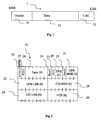
- MAC frames consisting of physical frames (or "bursts" comprise PDUs (standing for "Packet Data Units").
- PDUs Physical frames
- Each PDU comprises a header, data and a CRC (standing for "Cyclic Redundancy Check”).
- the CRC makes it possible to check whether the packet is in error.
- the header is itself protected by an HCS (standing for "Header Check Sum”) making it possible to disregard an erroneous header.
- the length of the PDUs is variable and is indicated in the header. Also, according to a first known implementation, when the HCS of a PDU is erroneous, the current PDU and the PDUs following are not taken into account.
- the IEEE802.16 standard envisages an optional mechanism for retrieving the start of the following PDUs, this mechanism being called "Transmission Convergence Sublayer".
- the physical frame is divided into several data segments (for example OFDM symbols) protected by a Reed-Solomon code.
- the Reed-Solomon decoder can indicate to the DLC (standing for "Data Link Control") layer that the current segment is good.
- a specific byte is inserted at the start of each segment to indicate the start of the next PDU commencing in the segment considered.
- This technique nevertheless presents the drawback of being relatively complex (processing of a signal arising from a Reed-Solomon decoder) and consumes bandwidth.
- the invention is aimed at alleviating these drawbacks of the prior art.
- the invention is aimed at allowing synchronization on the data packets received, when the header of these data packets comprises error detection means, while limiting bandwidth consumption.
- the invention proposes a method according to claim 1.
- the method comprises a step of third check that a second data set which would be protected by a second error detection code, does not comprise any error, the frame comprising the second data set, the second data set itself comprising the first data set.
- the method comprises a step of reading in the first set, of a cue representative of the length of the second set.
- the frame is compatible with an IEEE802.16 standard.
- the method comprises the steps of:
- the invention also relates to a module according to claim 6.
- the first checking means comprise a plurality of first decoders of the first code, at least part of the first decoders respectively decoding data sets arising from the frame, shifted temporally.
- the module comprises second means of checking that a second data set which would be protected by a second error detection code, does not comprise any error, the frame comprising the second data set, the second data set itself comprising the first data set.
- the second checking means comprise a plurality of second decoders of the second code.
- each of the second decoders is associated with one of the first decoders, the second decoder being suitable for checking a second data set comprising a first set, that a first decoder associated with the second decoder is suitable for checking.
- each of the second decoders is associated with the set of the first decoders, the second decoder being suitable for checking a second data set comprising a first set, that any one of the first decoders is suitable for checking.
- the module comprises means for distinguishing two operating modes:
- the invention also relates to a reception apparatus for receiving data frames, comprising means of reception of the frames and at least one synchronization module such as previously described according to the invention.
- FIG. 1 presents a PDU 1 according to the IEEE802.16 standard, which comprises:
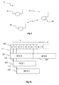
- Figure 2 specifies the structure of the header 10 which comprises:
- the HCS 20 makes it possible to detect errors in the header 10.
- Figure 3 represents a communication network 3 according to a particular embodiment of the invention.
- the network 3 is, for example, an IEEE802.16 wireless network and comprises:
- the access point 30 is able to send or receive MSDUs destined for the terminals 31 and 32 on the wireless link.
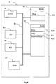
- Figure 4 diagrammatically illustrates an apparatus 4 corresponding to the access point 30 or to one of the terminals 31 and 32.
- the apparatus 4 comprises, linked together by an address and data bus 44, also transporting a clock signal:
- each of the elements 41 to 46 is well known to the person skilled in the art. These common elements are not described here.
- the word "register" used in the description of the memories 42 and 43 designates in each of the memories mentioned, either a memory area of small capacity (a few binary data) or a memory area of large capacity (making it possible to store an entire program or all or some of the data representative of an audio/video service received).
- the ROM memory 42 comprises in particular a program "prog" 420.
- the algorithms implementing the steps of the method described hereafter are stored in the ROM memory 42 associated with the apparatus 3 implementing these steps.
- the microprocessor 31 loads and executes the instructions of these algorithms.
- the random access memory 43 comprises in particular:
- FIG. 5 diagrammatically illustrates the synchronization module 47 which comprises:
- the header checking module 470 checks one or more bits having precise meanings in the header, in particular:
- these four bits are checked (for example by inputting the data to a shift register, and by checking whether bits 1, 9, 10 and 13 (starting from the high weights) are respectively equal to 0, 0, 1 and 0 (for example with the aid of inverting gates applied to bits 1, 9 and 13 and of an "AND" gate applied to the four bits 9 (inverted), 13 (inverted), 1 (inverted) and 10 and whose output when set to 1 indicates that it may involve a header.
- This output can be used directly by the block 470 as command for the block 471.
- bits 1, 9, 10 and 13 are compared directly with the expected value.
- the block 471 calculates the HCS of a set of six data bytes as a function of the command transmitted by the block 470.
- the block 471 dispatches a correct HCS signal to monitoring module 473 and to the block 472. It also dispatches a cue of length of the PDU to the block 472, this length being identified with the presumed location of the field 21 in the tested block of six bytes.
- This length information can be transmitted in an explicit manner to the block 472 according to certain embodiment or implicit manner if the block 471 itself detects (with the aid of a counter initialized to the value of the length) the presumed end of the PDU (the command signal taking a predetermined value during the reception of the PDU by the block 472).
- the block 472 When the block 472 receives a CRC calculation command cue from the block 471, it calculates the CRC of the data received synchronized on the reception of the data by the blocks 470 and 471. Thereafter, the block 472 transmits a detected CRC signal to the monitoring module when the CRC is correct.
- the monitoring module 473 receives a correctly or incorrectly decoded HCS indication from the block 471, a correctly or incorrectly decoded CRC indication and the content of a header corresponding to a PDU whose CRC and HCS are correct, these cues being provided by the block 472. Thereafter, the module 473 transmits to the CPU 41 a synchronization search and/or HCS and CRC check result signal 478 indicating that the module 47 has been able to synchronize on a received PDU and/or has been able to check that the CRC and HCS of a received PDU are correct.
- the signal 478 comprises, for example, a synchronization on PDU performed indication and, if the PDU synchronization has been able to be performed and/or the corresponding HCS and CRC are correct, the header of the corresponding PDU (thereby allowing the CPU to have directly the information that it can use directly (in particular the length of the PDU)) and its position of the PDU in the memory (for example, position of the first byte of the PDU).
- the synchronization module 47 is an electronic block comprising one or more discrete components (for example of the programmable ASIC or programmable component type) or inserted totally or in part in a component comprising other functions (for example ASIC comprising the memories 42 and/or 43 and/or the CPU 41). According to other embodiments of the invention, the module 47 is implemented totally or partially in computer form (for example, by a signal processor).
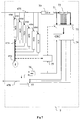
- Figure 6 illustrates an electronic implementation of the blocks 471 and 472 as well as of the module 473.
- the synchronization module is used not only to perform a synchronization on a PDU when said synchronization is lost (the mode of operation of the module 47 being termed unsynchronized PDU mode), but also to check a PDU HCS and a CRC when the PDU synchronization is not lost (the mode of operation of the module 47 being termed synchronized PDU mode).
- the CRC and HCS calculation resources are, at least in part, also used for the conventional CRC and HCS check employing an inexpensive modification and the loss of synchronization can be detected directly by the module 47, which can react accordingly without additional intervention of the outside elements.
- an additional signal of explicit synchronization request can be transmitted by the CPU 41, the CPU 41 being able at any moment to change the status of the PDU synchronization in the component 47 (for example, as a function of outside information).
- the block 471 comprises six HCS decoders 4700 to 4705 supplied with data originating from the bus 475.
- Each of the decoders 4700 to 4705 is supplied with a shift corresponding to a byte so as to be able to process in parallel blocks of six bytes that may be PDU headers.
- Figure 10 illustrates this shift.
- the first decoder 4700 begins to decode at the instant 111 a data block 101 of six bytes.
- the second decoder 4701 begins to decode at the instant 112, a data block 102 of six bytes.
- the second decoder 4701 begins to decode at the instant 112, a data block 103 of six bytes and so on and so forth.
- the decoder 4700 can check the block 104 shifted by six bytes with respect to the block 101.
- the block 471 can check in a continuous manner the CRCs of the incoming data.
- the block 472 comprises six CRC decoders 4710 to 4715 supplied with data originating from the bus 475.
- Each of the decoders 4710 to 4715 is associated with a decoder 4700 to 4750, the supply of the decoders 4710 to 4715 being synchronous with that of the associated HCS decoder with a shift of a fixed number of bytes that is greater than or equal to six so as to take into account the processing time by the HCS decoder.
- a decoder has checked the CRC corresponding to a packet and if this CRC is correct, a synchronization is performed and it sends a correct CRC signal as well as the content of the header of the synchronized PDU.
- a decoder can also only transmit the correct CRC signal, the information regarding header and/or positioning of the PDU (typically the value of the counter corresponding to the start of the PDU) can be read moreover by, in particular, the CPU 41 and/or any element of the module 47.
- the module 473 comprises:
- the state machine 4732 is initialized by the writing to a specific reinitialization address of a predetermined data item (for example binary data item), this initialization being performed by the CPU 41.
- the machine sets to zero a counter of bytes entering the module 47 and its mode is by default synchronized PDU mode (on initialization, the received frame is considered to be synchronized by the machine 4732 and the CPU 41).
- the module 473 also comprises "AND" gates 600 to 605 linking respectively an HCS decoder 4700 to 4705 to a CRC decoder 4710 to 4715 whose input comprises the result of the output of a corresponding HCS decoder and the CRC decoding authorization transmitted by the machine 4732.
- These gates are supplied with a correct CRC signal originating from the corresponding HCS decoder and a signal originating from the machine 4732 and transmit the result of the operation to the corresponding CRC decoder and to an "OR" gate 4733.
- the state machine 4732 drives, in effect, the AND gates 600 to 605 to indicate to the CRC decoders 4710 to 4715 whether they are authorized to work or not, with the aid of a signal for monitoring the CRC decoders.
- this signal indicates only to the CRC decoder 4710 to 4715 that processes the PDU that it can check the CRC corresponding to this packet.
- this monitoring signal is active and authorizes the CRC check to all the CRC decoders 4710 to 4715 so long as a PDU synchronization has not been performed.
- the output of the "OR" gate 4733 is linked to an input of the machine 4732 and makes it possible to indicate that a header HCS that may correspond to a PDU start is correct. In synchronized PDU mode, the machine 4732 thus has directly the HCS check result on a PDU start.
- unsynchronized PDU mode when the state machine 4732 has obtained information on a data block all of whose parameters (checked bits, HCS, length and CRC) are compatible with a PDU, it transmits an information signal to the CPU 41.
- synchronized PDU mode when the machine 4732 has been able to check the HCS and the CRC of a PDU, it transmits it to the CPU 41.
- the PDU synchronization and/or CRC and/or HCS check result is transmitted spontaneously by the module 47 to the CPU 41.
- the CPU 41 reads the result after the transmission of the complete data block to the module 47 in synchronized mode or at predetermined instants or following a particular event in unsynchronized PDU mode.
- the HCS modules are grouped into a single HCS check block.
- each HCS decoder is associated with several CRC decoders.
- an HCS decoder detects a first block of six bytes with a correct HCS, it can instruct a first CRC decoder to check the CRC of the block beginning with this first block of six bytes and of a length corresponding to the length presumed field inside the first block of six bytes. If the HCS decoder again detects a correct CRC in a second block of six bytes while the first decoder is checking the CRC of the data block corresponding to the first block of six bytes, it can entrust to a second CRC decoder the checking of the CRC of a data block which begins with the second block of six bytes. In this way, if n CRC decoders are associated with an HCS decoder, then there can simultaneously be n CRC check for blocks beginning with headers shifted by an integer number of times six bytes.
- the module 47 comprises several HCS decoders and several CRC decoders, the CRC decoders possibly being associated with any HCS decoder.
- a CRC decoder can check the CRC of a first data block on the basis of a command originating from a first HCS decoder and when it has terminated this check verify the CRC of a second data block on the basis of a command originating from another HCS decoder.
- the CRC decoding resources are shared by all the HCS decoders and are thus optimized. According to this variant embodiment of the invention, it is possible to have less than six CRC decoders for six HCS decoders.
- the module 47 is used only to retrieve a lost PDU synchronization corresponding to the unsynchronized PDU mode previously described.
- Figure 7 illustrates a simplified embodiment 7 of the synchronization module 47 implementing only a CRC module 74.
- the synchronization module 7 comprises HCS decoders 4700 to 4705 similar to the HCS decoders which bear the same references in the module 47.
- the decoder 74 When the decoder 74 has checked the CRC corresponding to a packet and if this CRC is correct, a synchronization is performed and it sends a correct CRC signal as well as the content of the header of the synchronized PDU to the machine 77.
- the state machine 77 receives as input the output of the gate 4731 and indications on a data block (originating from the decoder 74) of which:
- the state machine 77 is initialized by the writing to a specific reinitialization address of a predetermined data item (for example binary data item), this initialization being performed by the CPU 41.
- the machine sets to zero a counter of bytes entering the 7 and its mode is by default synchronized PDU mode (on initialization, the received frame is considered to be synchronized by the machine 77 and the CPU 41).
- the machine 77 moreover gives a result in the same way as the machine 4732.
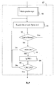
- Figure 8 describes a procedure for receiving data with synchronization on PDU, this procedure being implemented in the previously illustrated synchronization modules or, more generally, by modules of any type making it possible to identify PDU tarts following a loss of synchronization.
- the receiver of physical frames containing PDUs initializes its various components and variables.
- the receiver waits and receives a physical frame of data containing PDUs (for example frame of the IEEE802.16 type), each frame comprising PDUs with header protected by an HCS and data, the PDU itself being protected by a CRC, the length of the PDU being specified in the header.
- PDUs for example frame of the IEEE802.16 type
- the receiver checks whether the HCS of the current first block of six bytes is correct.
- the receiver extracts the length of the current PDU from the header.
- the receiver checks whether the PDU whose header corresponds to the current block of six bytes and which has as length the length defined in the course of step 83, has a correct CRC.
- the current block is considered to be a correct PDU and is transmitted to the associated application.
- the current block is considered to be a bad PDU and is eliminated.
- the receiver checks whether the current block is the last block of the frame.
- step 81 the frame end is detected and step 81 is repeated.
- the first block of six bytes which follows the current block (associated with the PDU), is considered to be the new current block of six bytes and step 82 is repeated.
- the receiver If the result of the test 82 is negative, the receiver has lost the synchronization on the PDUs, and in the course of a step 87, the receiver tests the HCSs in a sliding window of blocks of six bytes to retrieve a synchronization, and checks the CRC of a corresponding block so as to identify a PDU. This process stops at the end of the frame if no PDU is identified.
- the receiver checks whether a synchronization has been performed (a PDU having been identified).
- step 89 is executed. Otherwise, the frame end is reached without PDU synchronization and step 81 is repeated.
- Step 9 details the operations implemented in step 87.
- This step is, for example, implemented by a microprocessor (for example in the form of a specific task integrated with the program present in the register 430) or by one or more electronic components (for example programmable component or ASIC).
- a microprocessor for example in the form of a specific task integrated with the program present in the register 430
- one or more electronic components for example programmable component or ASIC.
- Step 87 begins with a step 90, in the course of which the receiver waits then receives a PDU synchronization command (for example monitoring bit set to 1 driving all ANDs 600 to 605).
- a PDU synchronization command for example monitoring bit set to 1 driving all ANDs 600 to 605.
- the command is replaced with a signal authorizing or not authorizing PDU synchronization.
- the receiver searches for one or more specific bits in a sliding window of two consecutive bytes in the frame received or detects a frame end.
- the specific bit or bits are in particular among the bits having precise meanings in the header, and for example:
- the search for bits can be done on the four bits 22 to 25 situated at precise locations.
- this comparison is, for example performed by applying to the two bytes a mask corresponding to the location of the bits searched for with the aid of an "AND" operation (in the case of a search for the four bits 22 to 25 such as illustrated in Figure 2 , the mask applied is 1000000011001000 in binary notation). Then, we check whether the result is equal to 00000000010000000.
- the receiver checks whether the preceding step has stopped following an end-of-frame detection (this operation can correspond to an initialization operation related to a frame end or a synchronization performed by another PDU synchronization or CRC checking module).
- step 47 is terminated.
- the receiver checks whether the block of six consecutive bytes of the received frame beginning with the two bytes where the bit or bits searched for have been detected has a correct HCS.
- step 91 the HCS of the tested block of six bytes is not correct and step 91 is repeated.
- the receiver extracts the length field 21 in the corresponding block of six bytes (last three bits of the second byte and third byte).
- the receiver checks whether the block of n bytes (n representing the length 21) beginning with the block of six bytes with correct HCS has a correct CRC.
- step 91 the CRC of the tested block of n bytes is not correct and step 91 is repeated.
- step 47 the receiver has detected a block of n bytes corresponding with a very large probability to a PDU, and step 47 is terminated.
- the architecture of the reception apparatus can be different from that illustrated in Figure 4 , in the respective function and/or the form of the elements (the functions of the electronic elements can in particular be grouped together in a restricted number of components or, conversely, dispersed in several components) and their arrangement.
- the module for synchronization on PDUs can also have a different.structure, the translation functions possibly being in particular integrated with one of the modules associated with the registers.
- detection of synchronization can be done on any packet protected by an error detection code (for example HCS or CRC), the packet being of known length (for example fixed length or identified by any means, this length being equal to six or different from six) or unknown length (checking being done for various lengths or on a window of variable size).
- an error detection code for example HCS or CRC
- the packet being of known length (for example fixed length or identified by any means, this length being equal to six or different from six) or unknown length (checking being done for various lengths or on a window of variable size).
- a packet of known length makes it possible to simplify the implementation.
- the detection of the start of a packet can be done according to the method of claim 1.
- the presence or the value of predetermined data is checked, these data corresponding to expected compulsory values or to a particular mode of data transmission.
- the packet is included in one or more larger packets, each being protected by an error detection code, the absence of errors in the larger packet or packets is checked with the aid of this error detection code.
- the packet is included in one or more larger packets, the presence or the value of predetermined data is checked.
- the order of the steps of start-of-packet detection and of checking of presence or of values of predetermined data is arbitrary, it being possible for all or part of the checking step to be done before or after the detection step. Nevertheless, if the checking step is performed before the detection step, the implementation is generally simplified.
- the packet comprises one or more smaller packets, each being protected by an error detection code, the absence of errors in the smaller packet or packets is checked with the aid of this error detection code.
- a wireless communication standard for example IEEE802.16
- codes for detecting errors in a received packet for example IEEE802.16
- the invention is not limited to wireless transmissions but relates to all transmissions on any medium, and in particular on noisy wire channels or on a recording channel.
Landscapes
- Engineering & Computer Science (AREA)
- Computer Networks & Wireless Communication (AREA)
- Signal Processing (AREA)
- Mobile Radio Communication Systems (AREA)
- Synchronisation In Digital Transmission Systems (AREA)
- Detection And Prevention Of Errors In Transmission (AREA)
Claims (13)
- Verfahren zum Empfangen eines Rahmens, der Datenpakete umfasst, wobei jedes Datenpaket durch mindestens einen Fehlererkennungscode geschützt ist, wobei das Verfahren den folgenden Schritt umfasst:- erste Prüfung (82, 471, 93), dass ein erster Datensatz, der durch einen ersten Fehlererkennungscode geschützt würde, keinen Fehler umfasst, wobei der Rahmen den ersten Datensatz umfasst; wobei das Verfahren durch die folgenden Schritte gekennzeichnet ist:- zweite Prüfung (84, 470, 91) der Anwesenheit vorgegebener Daten in dem ersten Datensatz;- Synchronisation an einem der Pakete, die den Satz umfassen, falls die erste Prüfung angibt, dass der erste Datensatz keinen Fehler umfasst und falls die vorgegebenen Daten in dem ersten Datensatz vorhanden sind, wobei die Synchronisation auf der ersten Prüfung beruht.
- Verfahren nach Anspruch 1, dadurch gekennzeichnet, dass es einen Schritt einer dritten Prüfung (472, 95) umfasst, dass ein zweiter Datensatz, der durch einen zweiten Fehlererkennungscode geschützt würde, keinen Fehler umfasst, wobei der Rahmen den zweiten Datensatz umfasst, wobei der zweite Datensatz selbst den ersten Datensatz umfasst.
- Verfahren nach Anspruch 2, dadurch gekennzeichnet, dass es einen Schritt des Lesens (83) eines Hinweises, der die Länge des zweiten Satzes repräsentiert, in dem ersten Datensatz umfasst.
- Verfahren nach einem der Ansprüche 1 bis 3, dadurch gekennzeichnet, dass der Rahmen mit einer Norm IEEE802.16 kompatibel ist.
- Verfahren nach einem der Ansprüche 1 bis 4, dadurch gekennzeichnet, dass es die folgenden Schritte umfasst:- Empfang (81) von Datenrahmen;- Extraktion mindestens eines ersten Datenpakets, wobei der Anfang jedes ersten Datenpakets in Bezug auf den Anfang des Rahmens oder eines vorhergehenden Datenpakets identifiziert ist;- vierte Prüfung der Gültigkeit mindestens eines Teils jedes ersten Datenpakets mit Hilfe des ersten Fehlererkennungscodes;- Implementierung der Schritte der ersten Prüfung und der Synchronisation, wenn der Schritt der vierten Prüfung angibt, dass mindestens ein Teil eines ersten Datenpakets nicht gültig ist.
- Modul zur Synchronisation (7, 47) an einem Rahmen, der Datenpakete umfasst, wobei jedes Datenpaket durch mindestens einen Fehlererkennungscode geschützt ist, wobei das Modul umfasst:- erste Mittel zum Prüfen (471), dass ein erster Datensatz, der durch einen ersten Fehlererkennungscode geschützt würde, keinen Fehler umfasst, wobei der Rahmen den ersten Datensatz umfasst; wobei das Modul gekennzeichnet ist durch:- zweite Mittel (470) zum Prüfen der Anwesenheit vorgegebener Daten in dem ersten Datensatz;- Mittel zur Synchronisation (473) an einem der Pakete, die den Satz umfassen, falls die Prüfung angibt, dass der erste Datensatz keinen Fehler umfasst und falls die vorgegebenen Daten in dem ersten Datensatz vorhanden sind, wobei die Synchronisation auf der ersten Prüfung beruht.
- Modul nach Anspruch 6, dadurch gekennzeichnet, dass die ersten Prüfmittel mehrere erste Decoder (4700 bis 4705) des ersten Codes umfassen, wobei mindestens ein Teil der ersten Decoder jeweils Datensätze, die sich aus dem Rahmen ergeben, zeitlich verschoben decodieren.
- Modul nach einem der Ansprüche 6 und 7, dadurch gekennzeichnet, dass es Mittel zum Prüfen (472) umfasst, dass ein zweiter Datensatz, der durch einen zweiten Fehlererkennungscode geschützt würde, keinen Fehler umfasst, wobei der Rahmen den zweiten Datensatz umfasst, wobei der zweite Datensatz selbst den ersten Datensatz umfasst.
- Modul nach Anspruch 8, dadurch gekennzeichnet, dass die dritten Prüfmittel mehrere zweite Decoder (4700 bis 4705, 74) des zweiten Codes umfassen.
- Modul nach Anspruch 9, dadurch gekennzeichnet, dass jeder der zweiten Decoder mit einem der ersten Decoder verknüpft ist, wobei der zweite Decoder zum Prüfen eines zweiten Datensatzes, der einen ersten Satz umfasst, dass ein erster Decoder, der mit dem zweiten Decoder verknüpft ist, zur Prüfung geeignet ist, geeignet ist.
- Modul nach Anspruch 9, dadurch gekennzeichnet, dass jeder der zweiten Decoder mit dem Satz der ersten Decoder verknüpft ist, wobei der zweite Decoder zum Prüfen eines zweiten Datensatzes, der einen ersten Satz umfasst, dass irgendeiner der ersten Decoder zur Prüfung geeignet ist, geeignet ist.
- Modul nach einem der Ansprüche 6 bis 11, dadurch gekennzeichnet, dass es Mittel zum Unterscheiden zweier Betriebsarten umfasst:- einer Betriebsart, die synchronisiert genannt wird, wobei die Prüfmittel prüfen, dass einem synchronisierten Paket entsprechende Daten keinen Fehler umfassen;- einer Betriebsart, die unsynchronisiert genannt wird, wobei durch die Prüfmittel und durch die Synchronisationsmittel nach der Paketsynchronisation gesucht wird.
- Empfangsvorrichtung (4) zum Empfangen von Datenrahmen, dadurch gekennzeichnet, dass sie Mittel für den Empfang der Rahmen und mindestens ein Synchronisationsmodul gemäß einem der Ansprüche 6 bis 12 umfasst.
Priority Applications (1)
| Application Number | Priority Date | Filing Date | Title |
|---|---|---|---|
| EP12169518A EP2493110A1 (de) | 2006-03-13 | 2007-03-07 | Verfahren, modul und vorrichtung zum empfangen von datenpaketrahmen |
Applications Claiming Priority (2)
| Application Number | Priority Date | Filing Date | Title |
|---|---|---|---|
| FR0650841A FR2898446A1 (fr) | 2006-03-13 | 2006-03-13 | Procede, module et appareil de reception de trames de paquets de donnees |
| PCT/EP2007/052133 WO2007104686A1 (en) | 2006-03-13 | 2007-03-07 | Method, module and apparatus for receiving data packet frames |
Related Child Applications (1)
| Application Number | Title | Priority Date | Filing Date |
|---|---|---|---|
| EP12169518A Division EP2493110A1 (de) | 2006-03-13 | 2007-03-07 | Verfahren, modul und vorrichtung zum empfangen von datenpaketrahmen |
Publications (2)
| Publication Number | Publication Date |
|---|---|
| EP1997261A1 EP1997261A1 (de) | 2008-12-03 |
| EP1997261B1 true EP1997261B1 (de) | 2012-06-06 |
Family
ID=37199250
Family Applications (2)
| Application Number | Title | Priority Date | Filing Date |
|---|---|---|---|
| EP12169518A Withdrawn EP2493110A1 (de) | 2006-03-13 | 2007-03-07 | Verfahren, modul und vorrichtung zum empfangen von datenpaketrahmen |
| EP07726691A Active EP1997261B1 (de) | 2006-03-13 | 2007-03-07 | Verfahren, modul und vorrichtung zum empfangen von datenpaketrahmen |
Family Applications Before (1)
| Application Number | Title | Priority Date | Filing Date |
|---|---|---|---|
| EP12169518A Withdrawn EP2493110A1 (de) | 2006-03-13 | 2007-03-07 | Verfahren, modul und vorrichtung zum empfangen von datenpaketrahmen |
Country Status (8)
| Country | Link |
|---|---|
| US (1) | US8539316B2 (de) |
| EP (2) | EP2493110A1 (de) |
| JP (1) | JP5161120B2 (de) |
| KR (1) | KR101069356B1 (de) |
| CN (1) | CN101401347B (de) |
| BR (1) | BRPI0708541B1 (de) |
| FR (1) | FR2898446A1 (de) |
| WO (1) | WO2007104686A1 (de) |
Families Citing this family (6)
| Publication number | Priority date | Publication date | Assignee | Title |
|---|---|---|---|---|
| US7916641B2 (en) | 2006-06-29 | 2011-03-29 | Wi-Lan, Inc. | System and process for packet delineation |
| US20090249172A1 (en) * | 2008-03-26 | 2009-10-01 | Qualcomm Incorporated | Methods and apparatus for improved decoding of bursts that include multiple concatenated protocol data units |
| US8126014B2 (en) | 2008-04-09 | 2012-02-28 | Qualcomm Incorporated | Methods and apparatus for improved decoding of hybrid automatic repeat request transmissions |
| ES2734278T3 (es) * | 2009-05-08 | 2019-12-05 | Nokia Solutions & Networks Oy | Método, aparato y medio legible por ordenador que incorpora un programa para asignación de recursos |
| KR102609758B1 (ko) | 2018-03-27 | 2023-12-04 | 삼성전자주식회사 | 데이터 통신 오류를 검출하는 순환 중복 검사 유닛 데이터 통신 장치 및 검출 방법 |
| US11108894B2 (en) * | 2019-08-09 | 2021-08-31 | Microsoft Technology Licensing, Llc | Masked packet checksums for more efficient digital communication |
Family Cites Families (10)
| Publication number | Priority date | Publication date | Assignee | Title |
|---|---|---|---|---|
| DE4036818C1 (de) * | 1990-11-19 | 1992-01-09 | Ant Nachrichtentechnik Gmbh, 7150 Backnang, De | |
| JP3153432B2 (ja) | 1994-03-31 | 2001-04-09 | 株式会社日立製作所 | セル多重化装置 |
| CA2145017C (en) * | 1994-03-31 | 2000-02-15 | Masaru Murakami | Cell multiplexer having cell delineation function |
| US5570388A (en) * | 1994-09-27 | 1996-10-29 | Digital Ocean, Inc. | Method and apparatus using simple codes for the wireless transmission of non-data symbols |
| US5774469A (en) * | 1996-04-01 | 1998-06-30 | Telefonaktiebolaget Lm Ericsson | Combined minicell alignment and header protection method and apparatus |
| US6819658B1 (en) * | 1997-07-15 | 2004-11-16 | Comsat Corporation | Method and apparatus for segmentation, reassembly and inverse multiplexing of packets and ATM cells over satellite/wireless networks |
| JP3449204B2 (ja) * | 1998-01-23 | 2003-09-22 | ソニー株式会社 | 制御装置、無線伝送装置及び無線伝送方法 |
| CA2273522C (en) * | 1999-06-01 | 2009-03-24 | Nortel Networks Corporation | High speed ethernet based on sonet technology |
| EP1107477B1 (de) * | 1999-12-01 | 2009-09-30 | Alcatel Canada Inc. | Verfahren und Gerät für eine Schnittstelle der physikalischen Schicht in einem drahtlosen Kommunikationssystem |
| JP4582023B2 (ja) * | 2006-03-07 | 2010-11-17 | ソニー株式会社 | 通信装置,受信方法,およびコンピュータプログラム |
-
2006
- 2006-03-13 FR FR0650841A patent/FR2898446A1/fr active Pending
-
2007
- 2007-03-07 CN CN2007800092035A patent/CN101401347B/zh active Active
- 2007-03-07 WO PCT/EP2007/052133 patent/WO2007104686A1/en not_active Ceased
- 2007-03-07 EP EP12169518A patent/EP2493110A1/de not_active Withdrawn
- 2007-03-07 BR BRPI0708541-9A patent/BRPI0708541B1/pt active Search and Examination
- 2007-03-07 KR KR1020087021134A patent/KR101069356B1/ko active Active
- 2007-03-07 US US12/225,017 patent/US8539316B2/en active Active
- 2007-03-07 JP JP2008558782A patent/JP5161120B2/ja active Active
- 2007-03-07 EP EP07726691A patent/EP1997261B1/de active Active
Also Published As
| Publication number | Publication date |
|---|---|
| KR20080106210A (ko) | 2008-12-04 |
| US8539316B2 (en) | 2013-09-17 |
| BRPI0708541B1 (pt) | 2019-09-24 |
| CN101401347B (zh) | 2013-05-08 |
| EP2493110A1 (de) | 2012-08-29 |
| EP1997261A1 (de) | 2008-12-03 |
| US20090296921A1 (en) | 2009-12-03 |
| KR101069356B1 (ko) | 2011-10-04 |
| JP5161120B2 (ja) | 2013-03-13 |
| JP2009530878A (ja) | 2009-08-27 |
| CN101401347A (zh) | 2009-04-01 |
| WO2007104686A1 (en) | 2007-09-20 |
| BRPI0708541A2 (pt) | 2011-05-31 |
| FR2898446A1 (fr) | 2007-09-14 |
Similar Documents
| Publication | Publication Date | Title |
|---|---|---|
| US7844884B2 (en) | Apparatus and method for processing bursts in a wireless communication system | |
| US8132079B2 (en) | Radio communication apparatus | |
| US7697535B2 (en) | Error resilient protocol data unit boundary detection | |
| EP1997261B1 (de) | Verfahren, modul und vorrichtung zum empfangen von datenpaketrahmen | |
| US7161955B1 (en) | Modified start frame delimiter detection | |
| CN101060384B (zh) | 通信设备和接收方法 | |
| JP2009272759A (ja) | 無線通信装置及び受信方法 | |
| US7870470B2 (en) | Method and apparatus for detecting synchronization of broadcasting channel in an asynchronous mobile communication system | |
| CN101171790A (zh) | 具有适应性选通偏移调整功能的接收机 | |
| JP3373745B2 (ja) | 可変長フレーム同期方法およびその装置ならびに可変長フレーム送信側装置 | |
| US7864815B2 (en) | Methods and apparatus for performing protocol data unit header re-synchronization in a communication system | |
| EP3142277B1 (de) | Fehlertoleranzverfahren und vorrichtung zur mikrowellenübertragung und computerlesbares speichermedium | |
| US7283565B1 (en) | Method and apparatus for framing a data packet | |
| JP2001258072A (ja) | 情報通信システム | |
| US20100322093A1 (en) | Communication device, communication system, and processing method by communication device | |
| GB2389492A (en) | A transmitter which combines a time slot identifier with a CRC value, and a receiver which extracts the identifier | |
| CN101742557A (zh) | 一种解析协议数据单元的装置及方法 | |
| JPH11186994A (ja) | Arq通信方法およびarq通信装置 | |
| JP2000252945A (ja) | フレーム同期装置及びフレーム同期方法 |
Legal Events
| Date | Code | Title | Description |
|---|---|---|---|
| PUAI | Public reference made under article 153(3) epc to a published international application that has entered the european phase |
Free format text: ORIGINAL CODE: 0009012 |
|
| 17P | Request for examination filed |
Effective date: 20080918 |
|
| AK | Designated contracting states |
Kind code of ref document: A1 Designated state(s): DE FR GB |
|
| RIN1 | Information on inventor provided before grant (corrected) |
Inventor name: FONTAINE, PATRICK Inventor name: GUGUEN, CHARLINE Inventor name: JEANNE, LUDOVIC |
|
| DAX | Request for extension of the european patent (deleted) | ||
| RBV | Designated contracting states (corrected) |
Designated state(s): DE FR GB |
|
| RAP1 | Party data changed (applicant data changed or rights of an application transferred) |
Owner name: THOMSON LICENSING |
|
| 17Q | First examination report despatched |
Effective date: 20100803 |
|
| GRAP | Despatch of communication of intention to grant a patent |
Free format text: ORIGINAL CODE: EPIDOSNIGR1 |
|
| GRAS | Grant fee paid |
Free format text: ORIGINAL CODE: EPIDOSNIGR3 |
|
| GRAA | (expected) grant |
Free format text: ORIGINAL CODE: 0009210 |
|
| AK | Designated contracting states |
Kind code of ref document: B1 Designated state(s): DE FR GB |
|
| REG | Reference to a national code |
Ref country code: GB Ref legal event code: FG4D |
|
| REG | Reference to a national code |
Ref country code: DE Ref legal event code: R096 Ref document number: 602007023153 Country of ref document: DE Effective date: 20120809 |
|
| PLBE | No opposition filed within time limit |
Free format text: ORIGINAL CODE: 0009261 |
|
| STAA | Information on the status of an ep patent application or granted ep patent |
Free format text: STATUS: NO OPPOSITION FILED WITHIN TIME LIMIT |
|
| 26N | No opposition filed |
Effective date: 20130307 |
|
| REG | Reference to a national code |
Ref country code: DE Ref legal event code: R097 Ref document number: 602007023153 Country of ref document: DE Effective date: 20130307 |
|
| REG | Reference to a national code |
Ref country code: FR Ref legal event code: PLFP Year of fee payment: 10 |
|
| REG | Reference to a national code |
Ref country code: FR Ref legal event code: PLFP Year of fee payment: 11 |
|
| REG | Reference to a national code |
Ref country code: DE Ref legal event code: R082 Ref document number: 602007023153 Country of ref document: DE Representative=s name: DEHNS, DE Ref country code: DE Ref legal event code: R082 Ref document number: 602007023153 Country of ref document: DE Representative=s name: DEHNS PATENT AND TRADEMARK ATTORNEYS, DE Ref country code: DE Ref legal event code: R082 Ref document number: 602007023153 Country of ref document: DE Representative=s name: HOFSTETTER, SCHURACK & PARTNER PATENT- UND REC, DE |
|
| REG | Reference to a national code |
Ref country code: FR Ref legal event code: PLFP Year of fee payment: 12 |
|
| REG | Reference to a national code |
Ref country code: DE Ref legal event code: R082 Ref document number: 602007023153 Country of ref document: DE Representative=s name: DEHNS, DE Ref country code: DE Ref legal event code: R081 Ref document number: 602007023153 Country of ref document: DE Owner name: INTERDIGITAL CE PATENT HOLDINGS SAS, FR Free format text: FORMER OWNER: THOMSON LICENSING, ISSY-LES-MOULINEAUX, FR Ref country code: DE Ref legal event code: R082 Ref document number: 602007023153 Country of ref document: DE Representative=s name: DEHNS PATENT AND TRADEMARK ATTORNEYS, DE |
|
| REG | Reference to a national code |
Ref country code: GB Ref legal event code: 732E Free format text: REGISTERED BETWEEN 20190926 AND 20191002 |
|
| PGFP | Annual fee paid to national office [announced via postgrant information from national office to epo] |
Ref country code: DE Payment date: 20250327 Year of fee payment: 19 |
|
| PGFP | Annual fee paid to national office [announced via postgrant information from national office to epo] |
Ref country code: FR Payment date: 20250324 Year of fee payment: 19 |
|
| PGFP | Annual fee paid to national office [announced via postgrant information from national office to epo] |
Ref country code: GB Payment date: 20250325 Year of fee payment: 19 |