EP1996754B1 - Microcreping traveling sheet material - Google Patents
Microcreping traveling sheet material Download PDFInfo
- Publication number
- EP1996754B1 EP1996754B1 EP07717709A EP07717709A EP1996754B1 EP 1996754 B1 EP1996754 B1 EP 1996754B1 EP 07717709 A EP07717709 A EP 07717709A EP 07717709 A EP07717709 A EP 07717709A EP 1996754 B1 EP1996754 B1 EP 1996754B1
- Authority
- EP
- European Patent Office
- Prior art keywords
- pressing member
- primary pressing
- plastic
- primary
- retarder
- Prior art date
- Legal status (The legal status is an assumption and is not a legal conclusion. Google has not performed a legal analysis and makes no representation as to the accuracy of the status listed.)
- Active
Links
- 239000000463 material Substances 0.000 title claims abstract description 278
- 238000003825 pressing Methods 0.000 claims abstract description 275
- 229920003023 plastic Polymers 0.000 claims abstract description 136
- 239000004033 plastic Substances 0.000 claims abstract description 136
- 238000003892 spreading Methods 0.000 claims abstract description 26
- 229920000098 polyolefin Polymers 0.000 claims abstract description 12
- 239000000088 plastic resin Substances 0.000 claims abstract description 10
- 230000000979 retarding effect Effects 0.000 claims description 54
- 238000011282 treatment Methods 0.000 claims description 51
- 239000004699 Ultra-high molecular weight polyethylene Substances 0.000 claims description 23
- 229920000785 ultra high molecular weight polyethylene Polymers 0.000 claims description 23
- 239000004696 Poly ether ether ketone Substances 0.000 claims description 22
- 229920002530 polyetherether ketone Polymers 0.000 claims description 22
- 229920001778 nylon Polymers 0.000 claims description 19
- 229920001577 copolymer Polymers 0.000 claims description 18
- 239000000126 substance Substances 0.000 claims description 18
- 238000012360 testing method Methods 0.000 claims description 18
- 238000000034 method Methods 0.000 claims description 17
- 239000000470 constituent Substances 0.000 claims description 16
- 239000000203 mixture Substances 0.000 claims description 16
- 239000004677 Nylon Substances 0.000 claims description 15
- 229920002302 Nylon 6,6 Polymers 0.000 claims description 9
- 230000007704 transition Effects 0.000 claims description 8
- 230000009471 action Effects 0.000 claims description 7
- 230000015572 biosynthetic process Effects 0.000 claims description 7
- 230000001627 detrimental effect Effects 0.000 claims description 3
- 229920005672 polyolefin resin Polymers 0.000 claims description 2
- 229920001169 thermoplastic Polymers 0.000 abstract description 46
- 239000004416 thermosoftening plastic Substances 0.000 abstract description 46
- 239000002184 metal Substances 0.000 abstract description 29
- 229910052751 metal Inorganic materials 0.000 abstract description 29
- 229920001131 Pulp (paper) Polymers 0.000 abstract description 18
- 229920001903 high density polyethylene Polymers 0.000 abstract description 2
- 239000004700 high-density polyethylene Substances 0.000 abstract description 2
- -1 polypropylene Polymers 0.000 description 28
- 239000004698 Polyethylene Substances 0.000 description 18
- 229910000831 Steel Inorganic materials 0.000 description 18
- 229920000573 polyethylene Polymers 0.000 description 18
- 239000010959 steel Substances 0.000 description 18
- 239000011347 resin Substances 0.000 description 17
- 229920005989 resin Polymers 0.000 description 17
- 230000000694 effects Effects 0.000 description 16
- 238000010438 heat treatment Methods 0.000 description 16
- 239000000835 fiber Substances 0.000 description 15
- 238000000576 coating method Methods 0.000 description 14
- 239000000976 ink Substances 0.000 description 14
- 239000004743 Polypropylene Substances 0.000 description 11
- 230000001617 migratory effect Effects 0.000 description 11
- 229920001155 polypropylene Polymers 0.000 description 11
- 238000001125 extrusion Methods 0.000 description 10
- 230000008569 process Effects 0.000 description 10
- 238000004519 manufacturing process Methods 0.000 description 8
- 238000002844 melting Methods 0.000 description 8
- 230000008018 melting Effects 0.000 description 8
- 239000004809 Teflon Substances 0.000 description 7
- 229920006362 Teflon® Polymers 0.000 description 7
- 239000011248 coating agent Substances 0.000 description 7
- 230000006870 function Effects 0.000 description 7
- 239000000123 paper Substances 0.000 description 7
- 239000010410 layer Substances 0.000 description 6
- 230000004888 barrier function Effects 0.000 description 5
- 239000002131 composite material Substances 0.000 description 5
- 238000007639 printing Methods 0.000 description 5
- 229910000639 Spring steel Inorganic materials 0.000 description 4
- 238000005299 abrasion Methods 0.000 description 4
- 230000008901 benefit Effects 0.000 description 4
- 238000010276 construction Methods 0.000 description 4
- 230000006378 damage Effects 0.000 description 4
- 239000000945 filler Substances 0.000 description 4
- NBVXSUQYWXRMNV-UHFFFAOYSA-N fluoromethane Chemical compound FC NBVXSUQYWXRMNV-UHFFFAOYSA-N 0.000 description 4
- 239000004615 ingredient Substances 0.000 description 4
- 239000002655 kraft paper Substances 0.000 description 4
- 239000003921 oil Substances 0.000 description 4
- 230000007480 spreading Effects 0.000 description 4
- 239000012815 thermoplastic material Substances 0.000 description 4
- 229920005992 thermoplastic resin Polymers 0.000 description 4
- 238000012546 transfer Methods 0.000 description 4
- VGGSQFUCUMXWEO-UHFFFAOYSA-N Ethene Chemical compound C=C VGGSQFUCUMXWEO-UHFFFAOYSA-N 0.000 description 3
- 239000005977 Ethylene Substances 0.000 description 3
- 238000009825 accumulation Methods 0.000 description 3
- 230000007423 decrease Effects 0.000 description 3
- 238000011161 development Methods 0.000 description 3
- 239000002985 plastic film Substances 0.000 description 3
- 229920000642 polymer Polymers 0.000 description 3
- 238000012545 processing Methods 0.000 description 3
- 230000002787 reinforcement Effects 0.000 description 3
- XLYOFNOQVPJJNP-UHFFFAOYSA-N water Substances O XLYOFNOQVPJJNP-UHFFFAOYSA-N 0.000 description 3
- OKTJSMMVPCPJKN-UHFFFAOYSA-N Carbon Chemical compound [C] OKTJSMMVPCPJKN-UHFFFAOYSA-N 0.000 description 2
- 229910001374 Invar Inorganic materials 0.000 description 2
- PXHVJJICTQNCMI-UHFFFAOYSA-N Nickel Chemical compound [Ni] PXHVJJICTQNCMI-UHFFFAOYSA-N 0.000 description 2
- 239000004775 Tyvek Substances 0.000 description 2
- 229920000690 Tyvek Polymers 0.000 description 2
- 230000001464 adherent effect Effects 0.000 description 2
- 238000005452 bending Methods 0.000 description 2
- 239000010960 cold rolled steel Substances 0.000 description 2
- 238000005056 compaction Methods 0.000 description 2
- 230000006835 compression Effects 0.000 description 2
- 238000007906 compression Methods 0.000 description 2
- 230000008602 contraction Effects 0.000 description 2
- 230000001419 dependent effect Effects 0.000 description 2
- 239000004744 fabric Substances 0.000 description 2
- 230000013011 mating Effects 0.000 description 2
- 230000005012 migration Effects 0.000 description 2
- 238000013508 migration Methods 0.000 description 2
- 229920006255 plastic film Polymers 0.000 description 2
- 230000000452 restraining effect Effects 0.000 description 2
- 229920002994 synthetic fiber Polymers 0.000 description 2
- 239000012209 synthetic fiber Substances 0.000 description 2
- 229920002799 BoPET Polymers 0.000 description 1
- 239000004593 Epoxy Substances 0.000 description 1
- 229910000760 Hardened steel Inorganic materials 0.000 description 1
- ZOKXTWBITQBERF-UHFFFAOYSA-N Molybdenum Chemical compound [Mo] ZOKXTWBITQBERF-UHFFFAOYSA-N 0.000 description 1
- 239000005041 Mylar™ Substances 0.000 description 1
- 238000003853 Pinholing Methods 0.000 description 1
- 229920004695 VICTREX™ PEEK Polymers 0.000 description 1
- 230000004308 accommodation Effects 0.000 description 1
- 239000000654 additive Substances 0.000 description 1
- 230000000996 additive effect Effects 0.000 description 1
- 239000000853 adhesive Substances 0.000 description 1
- 230000001070 adhesive effect Effects 0.000 description 1
- 239000004566 building material Substances 0.000 description 1
- 229910052799 carbon Inorganic materials 0.000 description 1
- 230000008859 change Effects 0.000 description 1
- 230000000052 comparative effect Effects 0.000 description 1
- 238000009833 condensation Methods 0.000 description 1
- 230000005494 condensation Effects 0.000 description 1
- 239000004020 conductor Substances 0.000 description 1
- 238000011109 contamination Methods 0.000 description 1
- 238000006073 displacement reaction Methods 0.000 description 1
- 230000003670 easy-to-clean Effects 0.000 description 1
- 229920001971 elastomer Polymers 0.000 description 1
- 230000002349 favourable effect Effects 0.000 description 1
- 239000010408 film Substances 0.000 description 1
- 239000002783 friction material Substances 0.000 description 1
- 230000020169 heat generation Effects 0.000 description 1
- 238000009998 heat setting Methods 0.000 description 1
- 230000006872 improvement Effects 0.000 description 1
- 238000001746 injection moulding Methods 0.000 description 1
- 229910052500 inorganic mineral Inorganic materials 0.000 description 1
- 238000003780 insertion Methods 0.000 description 1
- 230000037431 insertion Effects 0.000 description 1
- 238000009434 installation Methods 0.000 description 1
- 238000003475 lamination Methods 0.000 description 1
- 239000007788 liquid Substances 0.000 description 1
- 230000007774 longterm Effects 0.000 description 1
- 238000003801 milling Methods 0.000 description 1
- 239000011707 mineral Substances 0.000 description 1
- 238000012986 modification Methods 0.000 description 1
- 230000004048 modification Effects 0.000 description 1
- 229910052750 molybdenum Inorganic materials 0.000 description 1
- 239000011733 molybdenum Substances 0.000 description 1
- 229910052759 nickel Inorganic materials 0.000 description 1
- 239000004745 nonwoven fabric Substances 0.000 description 1
- 238000013021 overheating Methods 0.000 description 1
- 239000002245 particle Substances 0.000 description 1
- 229920000728 polyester Polymers 0.000 description 1
- 229920005594 polymer fiber Polymers 0.000 description 1
- 239000012783 reinforcing fiber Substances 0.000 description 1
- 230000004044 response Effects 0.000 description 1
- 230000000717 retained effect Effects 0.000 description 1
- 239000005060 rubber Substances 0.000 description 1
- 239000004576 sand Substances 0.000 description 1
- 238000006748 scratching Methods 0.000 description 1
- 230000002393 scratching effect Effects 0.000 description 1
- 230000035807 sensation Effects 0.000 description 1
- HBMJWWWQQXIZIP-UHFFFAOYSA-N silicon carbide Chemical compound [Si+]#[C-] HBMJWWWQQXIZIP-UHFFFAOYSA-N 0.000 description 1
- 229910010271 silicon carbide Inorganic materials 0.000 description 1
- 239000002356 single layer Substances 0.000 description 1
- 239000010935 stainless steel Substances 0.000 description 1
- 229910001220 stainless steel Inorganic materials 0.000 description 1
- 238000005728 strengthening Methods 0.000 description 1
- 239000000057 synthetic resin Substances 0.000 description 1
- 229920003002 synthetic resin Polymers 0.000 description 1
- BFKJFAAPBSQJPD-UHFFFAOYSA-N tetrafluoroethene Chemical group FC(F)=C(F)F BFKJFAAPBSQJPD-UHFFFAOYSA-N 0.000 description 1
- 239000004634 thermosetting polymer Substances 0.000 description 1
- 238000011144 upstream manufacturing Methods 0.000 description 1
- 238000003466 welding Methods 0.000 description 1
Images


Classifications
-
- D—TEXTILES; PAPER
- D06—TREATMENT OF TEXTILES OR THE LIKE; LAUNDERING; FLEXIBLE MATERIALS NOT OTHERWISE PROVIDED FOR
- D06C—FINISHING, DRESSING, TENTERING OR STRETCHING TEXTILE FABRICS
- D06C21/00—Shrinking by compressing
-
- B—PERFORMING OPERATIONS; TRANSPORTING
- B31—MAKING ARTICLES OF PAPER, CARDBOARD OR MATERIAL WORKED IN A MANNER ANALOGOUS TO PAPER; WORKING PAPER, CARDBOARD OR MATERIAL WORKED IN A MANNER ANALOGOUS TO PAPER
- B31F—MECHANICAL WORKING OR DEFORMATION OF PAPER, CARDBOARD OR MATERIAL WORKED IN A MANNER ANALOGOUS TO PAPER
- B31F1/00—Mechanical deformation without removing material, e.g. in combination with laminating
- B31F1/12—Crêping
- B31F1/14—Crêping by doctor blades arranged crosswise to the web
- B31F1/145—Blade constructions
Abstract
Description
- Under 35 U.S.C. §119(e)(1), this application claims the benefit of prior
U.S. provisional application 60/756,793, filed January 6, 2006 - This invention relates to the microcreping of traveling flexible sheet materials. It relates both to microcreping flexible sheet materials that have been difficult to microcrepe on a commercial basis due for example to heating or contamination problems, and to microcreping flexible sheet materials at higher speeds or with less wear on machine components than has been attainable previously.
- "Microcreping", sometimes called "Dry Microcreping," refers to longitudinal treatment of traveling flexible sheet materials under substantially dry conditions in which a drive force is produced by pressing the sheet material against a drive roll. This positively propels the material through a confined retarding passage, with microcreping action on the sheet material occurring in the transition between driving and retarding regions. Because such microcreping does not depend upon adhesion of the sheet material to the drive surface or a wet condition of the material, a particularly wide range of properties is obtainable (Note: The dry microcreping here described must not be confused with wet creping or creping based on adhesion, performed for instance on a Yankee Dryer. There have been instances in which such processes too have been referred to as "microcreping", though they are completely different processes, incapable of the results achievable with "dry microcreping".)
- "One roll microcreping", i.e. one roll dry microcreping, refers to microcreping that relies upon a single drive roll having a surface capable of mechanically gripping the inner face of the sheet material. A running length of the sheet material is pressed with considerable force face-wise against this moving surface by a stationary pressing member whose face is freely slippable (i.e. smoothly, continuously slippable) relative to the outward face of the material which it engages. Because of the variable geometry of the treatment region made possible with such an arrangement, a particularly wide range of treatments is possible.
- A "bladed microcreper" or bladed dry microcreper refers to a one roll microcreper in which retarding is dependent upon extrusion of the treated material between opposed retarder surfaces, the retarder on the roll side being of blade form.
- A "bladeless microcreper" or dry microcreper refers to a one roll-microcreper that does not have such a blade.
- Depending upon the nature of the flexible sheet material and the conditions of treatment, by microcreping with a one roll microcreper: individual fibers of a sheet material can be crimped while remaining an integral part of the sheet; minute crepes or coarser crepes can be formed in the sheet material as a whole; a desired degree of disruption of bonds between constituent fibers of a sheet material can occur; and softening, drapability and extensibility can be produced or enhanced. Heat-setting is typically employed when the treatment is of web materials having a thermoplastic component.
- In such ways, the traveling flexible sheet materials can be softened or rendered permanently elastic; their appearance and feel can be made more like cloth; absorptive qualities of sheet materials can be improved; sheet materials can be given an improved ability to drape or conform about objects; and other useful qualities can be imparted.
- Such microcreping is useful with a wide range of materials. For instance: nonwoven sheet materials comprised of natural fibers, synthetic fibers, or blends of the two kinds of fibers in single or multiple layers can be microcreped; plastic films or thicker plastic sheets, and nonwoven or fibrous sheets having a plastic film or metal coating or lamination can be microcreped; paper sheet materials and other sheet products produced from pulp can be microcreped, etc.
- The practical development of the one roll microcreper (dry microcreper) traces back to Richard R. Walton and his associates. For instance
U.S. Patent 3,260,778, issued July 12, 1966 , describes a bladed one-roll microcreper. A material-confining retarder passage is defined between an angled blade-form retarder on one side and a cooperating flexible retarder member on the other side of the material. The treated material is forced to move outwardly from between these retarders in an extruding action while continuously, freely slipping past the retarder surfaces.U.S. Patent 3,416,192 , (closest prior art) issued December 17, 1968 to Walton's licensee, is directed to such bladed one-roll microcreper. It specifies a thin sheet-form pressing member of spring, steel, molybdenum, nickel or Invar for pressing the material against the drive roll to advance the material through the compressive treatment cavity, and means for fine adjustment of the position of the sheet member in the plane of the sheet-form pressing member to regulate the compressive treatment of materials advancing through the treatment cavity.U. S. patent 3,810,280, issued May 14, 1974 , describes a bladeless one-roll microcreper that defines its retarder passage between the drive roll surface and an over-lying stationary retarder member which, rather than allowing the material to freely slip, engages and aggressively retards the material by a mechanical surface retarding effect (as opposed to retarding by confining the material to extrude between freely slippable surfaces, obtained with the bladed microcreper). Over the years, many variations of the one roll microcreper have been developed. A comb roll microcreper is shown inU.S. patent 4,090,385, issued May 23, 1978 and a bladed microcreper employing tangential extrusion is shown inU.S. Patent 4,894,196, issued Jan. 16, 1990 . Efforts to improve the system have continued over many years. For instanceU. S. patents 4,717,329, issued January 5, 1988 and5,060,349, issued October 29, 1991 , relate to a replaceable pre-assembled system of the stationary members of a microcreper andU.S. patent 5,666,703, issued September 16,1997 andU.S. patent 5,678,288, issued October 21, 1997 , relate to improvements for bladeless microcrepers. Each of these patents is referred to, to illustrate the decades-long effort to improve microcrepers and the wide variety of one roll microcreper arrangements that are possible. - During their long development the one roll microcreper (dry microcreper) treatments were found to be very sensitive to geometric and other variables. In particular it was determined to be vitally important to employ machine elements that are stable and uniform over time in the width and length dimensions of the machine. Bending or buckling, warping or puckering, lengthwise displacement or other geometrical variation of the stationary surfaces engaging the material in the critical driving and retarding regions could not be tolerated.
- In this respect, one of the basic findings for the one roll microcreper was the necessity to use a stationary hard metal member such as spring steel as the contact or "primary" pressing member to press the web material against the driven roll to drive the sheet material forward. The surface of this pressing member was formed by a low friction, heat-resistant coating applied to the metal member, typically DuPont's Teflon, with the strength and dimensional stability of the metal being relied upon to maintain the working surface within critical geometric tolerances. This pressing member was securely held so that a narrow area of its face could be pressed with controlled pressure into freely slippable relation upon the outer face of the flexible sheet material being treated. This pressed the inner face of the material against the gripping surface of the moving roll surface. The resulting strong engagement with the roll surface enabled the flexible sheet material to be positively, mechanically driven forward in its plane, the flexible sheet material slipping forward under the stationary pressing member in a continual motion, i.e., freely, without alternate slipping and stopping. By the stationary pressing member being principally of metal, it was found that the pressing member could be mechanically stable, i.e. without bending or buckling that would introduce non-uniformities to the treatment.
- Similarly, in the case of bladed microcreper arrangements, it was also found that the stationary retarder members should likewise be formed of steel or other metal with similar properties.
- By observing these conditions, for numerous sheet materials it was found that an acceptable balance was attainable between practical driving and retarding components, speed of operation, heating, wear-rate of the components and the need for a constant geometry of the treatment region across the width and throughout the length of the traveling material. But it also was found that there were significant limitations on use of the process. At desired production high rates, it was found that friction-generated heat at the stationary, freely slippable surfaces could harm many kinds of flexible sheet materials or cause heat distortion of the parts forming the drive and retarding region to disrupt the uniformity of the treatment. When treating many kinds of materials, the stationary slippable surfaces suffered undue wear. Because of such problems as overheating and undue wear, significant limitations on commercial use was thought to be inherent with respect to the kinds of materials that could be treated, the kinds of treatments that could be obtained, and the maximum speed of processing. In many cases, such production problems have made microcreping costly, in other cases microcreping seemed totally impractical.
- As an example, many web materials of polymer fibers could not be microcreped commercially for desired end effects because, at commercially acceptable speed, frictional heating of the polymer to high local temperatures produced an excessively deformed or melted polymer state in those regions. For instance, this produced sharp-edges on undulations of the material at the surfaces of the material, providing a harsh sensation to the touch. This has especially been the case for nonwoven material of polyolefin fibers such as polypropylene or polyethylene, which are low cost and widely preferred for the manufacture of disposable diapers, personal care products, etc. Likewise, microcreping plain films and laminates that include films of polypropylene or polyethylene produce sharp and abrasive crepe edges at the surface due to polymer melting that are not acceptable in many cases.
- As another example, microcreping of sheet material formed of wood pulp has been limited because of destruction of the stationary primary surface when the process is operated at desired high speeds. This has been the case for products produced of wood pulp such as Kraft papers and for nonwoven wipe products that have a high wood pulp content. In attempting microcreping of products formed of recycled wood pulp that contain abrasive fines, the pressing member, i.e. its low friction coating, and soon, the underlying steel surface itself, has been ruined over a brief period of operation.
- Other difficulties have arisen with microcreping due to the tendency of migratory substances such as inks to transfer from the materials being treated, producing accumulation of adherent deposits on the treatment surface that disrupt the treatment and involve costly down-time to remove. Another problem has been in respect of barrier coatings in which the process seemed to inherently produce pin holes in the barrier layer.
-
U.S. Patent Application 2004/0149414 discloses a wiper blade for wiping water from a sleeve mounted on a press roll in a paper making machine that is adjustably mounted on the machine for movement toward and away from the sleeve. The blade of polyethylene comes to a sharp edge where it contacts the polyethylene sleeve. The wiper blade is positionable against the surface of the sleeve to wipe water therefrom adjacent and upstream from the nip between the sleeve and a mating press roll. - International Application
WO 01/28766 -
EP Application 91303608.3 publication number 0 454 403 A1 ) discloses a doctor blade that is made with two sets of integral recesses. One set is shaped to retain the blade in a standard holder, the second set is shaped to act as a spring for biasing the blade within the holder. The blade may be made of metallic or a composite plastics material. - Prior papermaking doctor blades of different types were acknowledged to have been made of plastic
- We have found, despite common, long-established thinking that steel or similar metal components are required to define stationary members that freely slip on the material, that it is possible instead to form the surfaces by discretely formed members of plastic selected, in respect of the particular material to be treated, as to have physical integrity capable of performing their respective functions without undue friction, wear or distortion. Of particular importance in this regard is forming the stationary primary pressing surface of a one roll microcreper of such plastic. In preferred cases the plastic member is of discrete sheet-form plastic.
- In respect of the primary pressing member it has been found that thickness of the pressing member of about 0.1016 cm [0.040 inch] or greater is suitable to provide mass over which concentrated pressing and drag forces are distributed, so that stable geometry in the drive and retarding regions can be maintained.
- Other features concern preferred wear and friction property limits for the plastics, the discovery of suitability of certain specific thermoplastics, the use of special plastics to combat transfer of migratory substances such as inks. Plastics free of fiber reinforcement have been found to combat the problem of pin-holing of barrier film and the like. Preferred forms of the primary pressing member and a unitary extension include openings such as slots or holes in the plastic extension. For operation at temperature below about 104 °C [220 F], ultra high density polyethylene has been found to be a preferred thermoplastic material for the primary pressing member and the stationary retarding members.
- It has also been discovered that, by having a plastic primary pressing member define an extended load-spreading surface disposed in the cross-machine direction and facing in the direction of advance, the primary pressing member can be restrained without load concentration that distorts the working surface of the member. By forming this surface as a linear slideably engaged surface the plastic primary pressing member can be slideably inserted into its mounting during assembly. By making the slideable surfaces parallel to the axis of the roll, the primary pressing member comprised of the plastic is made free for cross-machine thermal expansion. Preferred mounting systems are simple to construct and can be used in existing microcreper machines. For instance the primary pressing member can be of sheet form, held between two mounting members at least one having a restraint formation engaged on a wall of the primary pressing member. The wall may be a rear wall of a groove in the plastic member, and the restraint formation a bar carried on a mounting member and inserted in the groove. Importantly, sheet materials of polypropylene, polyethylene and wood pulp can thus be desirably microcreped.
- Accordingly, two specific aspects of invention are provided , an apparatus for longitudinally, compressively treating, substantially in the plane of the material, a selected traveling flexible material of substantial width, and a method of treating the material employing the apparatus, the apparatus comprising a drive roll having a gripping surface constructed to mechanically engage a first face of the material when the material is in a substantially dry, unadhering state, a stationary pressing member constructed and mounted so that in a drive region a face of the stationary member can slippably engage and press face-wise against a second, opposite face of the material to force the first face of the material against the gripping surface of the roll to positively advance the material, and at least one stationary retarding member constructed and mounted to cause the retarding member to engage a face of the advancing material in a retarding region to retard the advancing material and cause compressive treatment of the material in a transition zone between the drive and retarding regions, wherein:
- at least one of the stationary members is a discrete wear member of plastic held in position to cause one of its surfaces to continually, slippably engage and apply pressure to the face of the traveling material for advancing or retarding the material, the plastic member having dimensions and being of such substance selected in respect of the selected material to be treated as to have physical integrity capable of performing its function without undue friction, wear or distortion.
- Preferred implementations of these aspects have one or more of the following features:
- The at least one stationary member of the plastic is the pressing member in the drive region, in preferred forms the pressing member comprising a primary pressing member of sheet-form of thickness greater than about 0.1016 cm [0.040 inch], the sheet-form primary pressing member being supported as a cantilever in a support region that precedes the drive region, the primary pressing member being associated with a pressure device constructed to apply, in the drive region, adjustable pressure substantially in a concentrated width-wise-extending line to an outwardly exposed side of the sheet-form primary pressing member, to force the opposite surface of the primary pressing member to press the traveling material against the gripping surface of the drive roll to cause positive advance of the material, the thickness of the plastic primary pressing member preventing detrimental deformation under the concentrated pressure of the pressure device.
- The retarding region comprises a retarding passage defined by two stationary retarding members arranged to continually, slippably engage opposite sides of the advancing sheet material in manner to apply retarding force as the treated material extrudes from between the members. Preferably, at least one of the retarding members is a sheet- or plate-form wear member of the plastic held in position to cause one of its surfaces to continually, slippapbly engage and apply pressure to the face of the advancing material to promote retarding of the material.
- One of the retarding members is a retarder plate-form member located on the same side of the material as is the drive roll and having a material-engaging diverting surface positioned at a substantial angle to divert the direction of travel of the advancing material, and the cooperating retarder member is a cantilever confining member extending forward from the pressing member in the direction of material travel, the cooperating retarder member being bent or capable of being bent to converge relatively to and then to extend substantially parallel to the diverting surface of the plate-form retarder member, to form therewith an extruding passage through which the treated material is forced to extrude. In preferred forms: the cooperating retarder member is a sheet-form wear member of the plastic held in position to cause one of its surfaces to continually, slippably engage and apply pressure to the face of the advancing material to promote retarding of the material, in certain preferred forms the cooperating retarder member of the plastic being of thickness between about 0.0127 cm [0.005 inch] and 0.0381 cm [0.015 inch] and a support member is arranged to provide support to the outer side of the cooperating retarder member.
- When in the form of a bladed microcreper, the cooperating retarder member of plastic is a sheet-form member formed independently of the stationary pressing member, the cooperating retarding member having a rearward margin held against an outwardly directed surface of the pressing member for support. Preferably a sheet form support member engages an outwardly directed surface of the retarder member.
- In the apparatus having one or both retarder members of the plastic, preferably the cooperating pressing member is a sheet-form wear member of plastic, it is held in position to cause one of its surfaces to continually, slippably engage and apply pressure to the face of the traveling material to promote advance of the material, the plastic pressing member having dimensions and being of such substance selected in respect of the selected material to be treated as to have physical integrity capable of performing its function without undue friction, wear or distortion, in some instances the cooperating retarder member being an integral extension of the pressing member, forming therewith a unitary part comprised of plastic, the cooperating member being the same thickness as the primary pressing member, or being of reduced thickness, depending upon the treatment desired. In some instance, in either form, the cooperating retarder member has a series of openings, e.g. holes or slots, in the material-engaging surface, the series of openings extending across the width of the traveling material.
- In blade-type microcrepers, the plate-form retarder (relative to which the cooperating retarder member converges and then extends substantially parallel to the diverting surface of the plate-form retarder member, to form therewith an extruding passage through which the treated material is forced to extrude), is a wear member of the plastic held in position to cause one of its surfaces to continually, slippably engage the face of the advancing material to promote retarding of the material.
- Preferred aspects of invention also concern the particular plastics selected. These aspects include:
- One or more of the stationary material-engaging surfaces is defined substantially by a plastic comprised substantially of a plastic resin selected from the group consisting of ultra high molecular weight polyethylene, nylon, polyetheretherketone and copolymers and compatible blends in which one or more of the foregoing is a constituent.
- One or more of the stationary surfaces is defined by a plastic having a wear coefficient less than about 100 under the test ASTM G-65.
- One or more of the stationary surfaces of plastic has a coefficient of friction of about 0.15 or less under the test ASTM D-1894.
- For adapting the apparatus to longitudinally compressively treat a predetermined flexible sheet material having a predetermined treatment temperature, the plastic of the one or more stationary members of plastic is selected to be stable at that temperature, to have a wear coefficient less than about 100 under the test ASTM G-65 and to have a coefficient of friction of about 0.15 or less under the test ASTM D-1894.
- For adapting the apparatus to longitudinally compressively treat a flexible sheet material comprised of a polyolefin resin, at least one of the stationary members is comprised substantially of a selected polyolefin or a copolymer or compatible blend in which it is a constituent; preferably the selected plastic resin is substantially comprised of ultra high molecular weight polyethylene or a copolymer or compatible blend in which it is a constituent.
- For adapting the apparatus to longitudinally compressively treat material at a temperature of treatment under about 104 °C [220 F], the at least one stationary member is comprised substantially of ultra high molecular weight polyethylene, nylon or polyetheretherketone or a copolymer or compatible blend in which one of the foregoing is a constituent.
- For adapting the apparatus to longitudinally compressively treat material at a temperature of treatment above about 104 °C [220 F], the stationary member is comprised substantially of nylon 6,6 or polyetheretherketone or a copolymer or compatible blend in which one of the foregoing is a constituent.
- For adapting the apparatus to longitudinally compressively treat substantially dry flexible sheet material comprised of wood pulp at an operating speed of about 243.84 m [800 feet] per minute or greater, the plastic of the stationary member is selected to have a wear coefficient less than about 100 under the test ASTM G-65; in preferred forms the plastic has a coefficient of friction of about 0.15 or less under the test ASTM D-1894.
- For adapting the apparatus to longitudinally compressively treat substantially dry flexible sheet material comprised of wood pulp at an operating speed of about 243.84 m [800 feet] per minute or greater, the stationary member is comprised substantially of ultra high molecular weight polyethylene, nylon or polyetheretherketone or a copolymer or compatible blend in which one of the foregoing is a constituent.
- For adapting the apparatus to longitudinally compressively treat selected material which carries a substance that is subject to migration to a plastic stationary member, the member is comprised of a plastic selected to resist or interfere with adhesion of the migratory substance. Preferred implementations have one or more of the following features: the plastic is a plastic resin that includes a substance that resists or interferes with adhesion of the migratory substance; the plastic is an oil-filled plastic; the selected material to be treated is comprised of polyethylene or a copolymer or blend in which polyethylene is a substantial constituent; the migratory substance is ink and the plastic of the stationary member is comprised substantially of an oil-filled nylon. For adapting the process to the treatment of flexible materials carrying a barrier layer or impermeable film or layer, plastic that is not fiber reinforced is employed.
- Other aspects of the invention concern the mounting of a sheet form plastic primary pressing member. These have one or more of the following features:
- The apparatus has a material-engaging device which includes a primary pressing member of the plastic in the drive region and at least one support member having a coefficient of thermal expansion substantially lower than that of the primary pressing member of plastic, the material-engaging device including a mounting of the primary pressing member constructed to permit its free cross-machine thermal expansion relative to the support member having the lower coefficient of thermal expansion. Preferred forms have one or more of the following features: the primary pressing member of plastic defines at least one extended load-spreading surface disposed in the cross-machine direction and facing in the direction of advance of the traveling material and a mounting includes a corresponding restraint surface engaged upon the load-spreading surface to resist drag force applied by the traveling material to the primary pressing member, preferably the load-spreading surface of the plastic primary pressing member and the corresponding restraint surfaces being linear surfaces constructed and arranged to be slideably engaged during assembly; preferably, the extended load-spreading surface is a linear surface that is disposed parallel to the axis of the drive roll, and the restraint surface is correspondingly linear and is slideably engaged upon the load-spreading surface to permit free cross-machine thermal expansion of the primary pressing member of plastic; preferably the load-spreading surface is provided by a wall formation of the primary pressing member, for instance the wall bounds a groove formed in the plastic body of the primary pressing member.
- In the apparatus, preferably, the primary pressing member is held between upper and lower mounting members that form part of an assembly, at least one of the mounting members providing a said restraint surface engaged upon the load-spreading surface to resist drag force applied by the traveling material to the primary pressing member. In this case, the implementation preferably has one or more of the following features: the mounting member extends forward over an upper face of the primary pressing member to an end lying forward, beyond the line of action of a pressing device and the lower mounting member extends forward to an end located to the rear of the pressing device; a linear load-spreading surface of the primary pressing member is the forwardly directed rear wall of a groove formed in an upper or lower surface of the primary pressing member and the liner restraint surface is defined by a rearwardly directed surface of a formation provided by the corresponding mounting member.
- In preferred forms, portions of the assembly to the rear of the primary pressing member are joined by a cross-machine series of fasteners held in a corresponding groove of a holder.
- Another important aspect of invention concerns methods of providing an apparatus having one or more of the features mentioned, and processing with it the various sheet materials mentioned above with respect to the features of the invention and the other materials mentioned elsewhere in this specification.
- Another aspect of invention concerns, per se, a primary pressing member constructed for use in an apparatus for longitudinally compressively treating a selected traveling flexible sheet material substantially in the plane of the material, the apparatus having a drive roll for advancing the material, at least one retarder engageable with the material driven forward by the roll, and a primary pressing member for pressing the material against the surface of the drive roll in a drive region before the material engages the retarder, the primary pressing member defining a material-engaging surface for continually slippably engaging the material, the surface extending cross-machine across the width of the material on the drive roll, and a pressing device to apply adjustable pressure to the primary pressing member to cause the primary pressing member to press the traveling material against the drive roll surface over a pressing region across the width of the material,
- wherein at least the portion of the primary pressing member constructed to engage the traveling flexible sheet material over the pressing region is a wear-member comprising plastic capable of continually, slippably engaging the traveling material, the plastic wear member having dimensions and being of such substance selected in respect of the selected material to be treated as to have physical integrity capable of performing its function without undue friction, wear or distortion.
- Preferred implementations of this aspect have one or more of the features described above generally with respect to stationary members of the apparatus, or described specifically with respect to the pressing member employed in the drive region of the apparatus.
- The details of one or more implementations are set forth in the accompanying drawings and the description below. Other features, objects, and advantages will be apparent from the description and drawings, and from the claims.
-
-
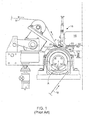
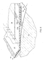
Fig. 1 is a side view of a standard microcreper machine of the prior art, without its primary assembly in place. -
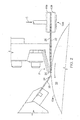
Fig. 2 is a magnified view of operative parts of a microcreper that employs a pressing assembly having a thermoplastic primary pressing member, the assembly held by a holder in the form of a pressure clamp, shown diagrammatically. -
Fig. 2A is a diagrammatic, perspective view, on magnified scale, of the operative portion of the machine ofFig. 2 , some parts being shown in cross-section, and with portions broken away for ease of illustration. -
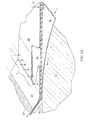
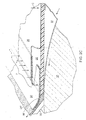
Figs. 2B and2C are diagrammatic, perspective views, similar toFig. 2A , employing other plastic members bounding a microcreper treatment cavity. -
Fig. 3 is an exploded view in cross-section of the parts of another pressing assembly, in this case the assembly being capable of being slid endwise into the holder ofFig. 1 ;Fig. 3A is a side view of the assembled parts;Fig. 3B is a greatly magnified view of the portion ofFig. 3 indicated by the circle; andFig. 3C is a cross-sectional, perspective view of this new pressing assembly. -
Fig. 4 is a magnified view of operative parts of the microcreper ofFig. 1 with the pressing assembly ofFigs. 3-3C in place whileFig. 4A is a diagrammatic, perspective view, on magnified scale, of the operative portion of the machine ofFig. 4 , some parts being shown in cross-section, and with portions broken away. -
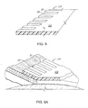
Fig. 5 is an exploded view, similar toFig. 3 , of the parts of a pressing assembly featuring another thermoplastic primary pressing member whileFig. 5A is a side view of the assembly. -
Fig. 5B is a cross-section of another primary pressing member capable of performing in manner similar to that ofFig. 5A . -
Fig. 6 is a diagrammatic, perspective view, similar toFig. 4A , but with the operative parts ofFig. 5A . -
Figs. 7 and 7A are magnified cross-sections of alternate versions of the primary pressing member held between upper and lower mounting members. -
Fig. 8 is a side cross-sectional view of another primary pressing member defining a step and reduced thickness at its downstream extension whileFig. 8A illustrates the primary pressing member ofFig. 8 in place, with material being treated in the cavity formed by the step. -
Fig 8B is a view similar toFig. 8 of a primary pressing member of greater thickness, intended for use as shown inFig. 8A but with out backing by a flexible member. -
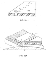
Fig. 9 is a cross-sectioned perspective view of another primary pressing member defining fingers in its downstream extension whileFig. 9A is a perspective view showing the primary pressing member in use on the machine. -
Fig. 10 is a cross-sectional view of another primary pressing member in which a series of apertures is formed through the thickness of the primary pressing member in the transition region whileFig. 10A is a perspective view showing the primary pressing member in use of the machine. - Like reference symbols in the various drawings indicate like elements.
-
Figure 1 shows a standard one roll microcreper machine of the type employing aretarder blade 30. The machine is shown with its pressing assembly (assembly or standard primary pressing member and flexible cooperating retarder) removed. This microcreper is commercially available from Micrex Corporation, Walpole, Massachusetts, USA. It is similar to the version of the machine shown inU.S. Patent 4,717,329 , but has a holder for the pressing assembly into which the rear margin of the pressing assembly is slid endwise in accordance withU.S. Patent 5,666,703 . The original version of this type of microcreper is shown inU.S. Patent 3,260,778 . While also similar to the standard microcreper ofFigure 1 , it employed a pressure clamp to secure the rear margin of the pressing assembly. Each of these patents is referred to, and in jurisdictions where permitted, is incorporated herein by reference with regard to structure and operation of the primary pressing and retarding assembly. - Referring to the present
Fig. 1 , a drivenroll 10, of 182.88 cm [72 inches] length in the cross-machine direction, has an outer cylindricalgripping surface 10a,Fig 2 , for mechanically engaging the surface of the flexible web material to be treated. For instance, thegripping surface 10a may be defined by fine silicon carbide particles applied to a steel roll by plasma coating. This gripping surface receives a continuous length of predetermined flexible sheet material (web material) M of selected width, up to 182.88 cm [72 inches]. Following microcreping, the treated material, M', is led away from the machine. Aholder 14 for the pressing assembly is carried onsupport member 16. The holder is constructed of lower and upper members, 42 and 44, respectively. These extend in the cross-machine direction, i.e., across the width of the machine. A rear margin of the pressing assembly is constructed to be held betweenmembers 42 and 44. The pressing assembly then projects in cantilever fashion in the direction of travel of the material M, to a position under apressure device 18.Pressure device 18 is constructed to apply downward force toshoe 20. The shoe in turn applies downward force, arrow P, to a narrow region across the full operating width of the primary pressing member of the assembly. Aretarder blade member 30 also extends across the full operating width. It is positioned to oppose forward thrust of driven material M while cooperating with a flexible sheet-form confining member 24 ("flexible cooperating retarder") on the opposite side of material M to define an extrusion passage for the treated material,Fig. 2 . Theretarder blade 30 and the opposed cooperating retardingmember 24 continuously slippably, i.e. freely, engage the opposite faces of the material M. The material is confined in the transition zone at the end of the primary pressing member. Movement of the microcreped material M' is retarded by extrusion effects due to cooperation of the retarding and the confining surface slippably pressing against the opposite sides of the material. As is standard with one roll microcrepers, material M, driven forward by the gripping surface of roll 10 (without adhesion to the roll), is microcreped (dry microcreped) in the small transition zone between thepressure shoe 20 and the extrusion passage defined by theretarder members -
Fig 2 and the remaining figures show examples of new microcreping cavities formed totally or in part of special plastic, preferably thermoplastic. - The examples of
Figs. 2 and 2A-2C employ sheet-form pressing members held by a clamping arrangement, similar to the technique employed in the original microcreper ofU.S. Patent 3,260,778 . The examples of the remaining figures employ the holder ofFig. 1 into which the pressing assembly is slid endwise. - Referring to
Figs. 2 and2A , the key feature is the plastic portion of primary pressingmember 22 that lies directly undershoe 20. The lower face is pressed against the outer face of traveling material M,Fig. 2A in response to the concentrated line of pressure P applied byshoe 20. This presses the inner face of material M into driven engagement with the gripping surface ofroll 10. For primary pressingmember 22 the plastic is selected to be friction- and wear-compatible with the surface of the predetermined web M and physically stable under the predetermined operating conditions selected to perform the function of the member. Preferably the plastic has a wear coefficient less than about 100 under the test ASTM G-65 (avoiding undue wear such as that observed with Teflon coatings). Preferably it has a coefficient of friction of about 0.15 or less under the test ASTM D-1894. Preferably the plastic is a thermoplastic having all of these properties. In presently preferred forms the plastic of primary pressingmember 22 consists substantially of nylon, polyetheretherketone (PEEK) or ultrahigh molecular weight polyethylene and copolymers and compatible blends in which one or more of the foregoing is constituent. Discrete members formed of other resins are also operable depending on the conditions of use. An example of a candidate material in relatively low-abrasion applications is self-supporting grades of copolymers of ethylene and tetrafluoroethylene, e.g. in self-supporting sheet or plate form. - In the example of
Figs. 2 and2A , the plastic primary pressing member, in present preferred implementations, a thermoplastic primary pressing member, is of extended sheet form and is coextensively backed (supported) by anoverlying backing member 26 of cold rolled steel. Both extend across the operative width of the machine and are held stationary at their rear margins. In this example the plastic primary pressing member is preferably greater than about 0.1016 cm [0.040 inch] thick, preferably between about 0.15875 and 0.3175 cm [1/16 and 1/8 inch (0.0625 inch and 0.125 inch)] in thickness. The cross-machine, rear margins of the sheet members of corresponding extent are gripped and secured together by a stationary clamp 14a, shown diagrammatically. Clamp 14A is activated in the direction of the arrow C by a pneumatic piston, not shown. By firmly clamping the rear margins, the primary pressingmember 22 andbacking member 26 remain stationary when the primary pressing member is subjected to forward drag force by the traveling material slipping under it. The primary pressing member resists the distorting tendencies of longitudinal tension applied by drag of the traveling sheet material and of the orthogonal face-wise compression applied by thepressing device pressure shoe 20. Thus under constant temperature and speed conditions, it is found that the treatment geometry can be constant throughout the width of the machine and throughout the processing of a supply roll of the flexible sheet material M. - In the example of
Figs. 2 and2A , the rear margin of a flexible steel confining member (flexible cooperating retarder) 24 is inserted between the forward margins of the plastic primary pressingmember 22 and theoverlying backer member 26. Cooperatingretarder member 24 then extends forward in position to be deflected byretarder blade member 30 to the upwardly angled form shown. In position it engages and presses against the side of the material as it emerges from under the primary pressingmember 22 while the material is slippably engaged on the opposite side by theretarder blade 30, establishing conditions for retarding by an extrusion effect. - In respect of differential thermal expansion of the plastic primary pressing
member 22 and metal parts with which it is associated, special steps are found that accommodate the effect and assure operability without geometric distortion. - The significant difference in the coefficient of thermal expansion of the plastic primary pressing member and the backing
member 24 to which it is clamped might appear to those of ordinary skill to prevent suitable operation due to danger of warping and unevenness of the treatment surfaces, but it is found to be accommodated by taking special steps described later herein. - In respect of selection of the plastic, in the special case of the traveling sheet material M to be microcreped being substantially comprised of a polyolefin, it is found advantageous in certain instances, for the primary pressing
member 22 also to be comprised substantially of a polyolefin. Ultra high molecular weight polyethylene is preferred. - Indeed for most flexible sheet materials, when the predetermined conditions of treatment include operating at temperature under about 104 °C [220 F], the primary pressing member, in the form of a wear member, it is presently preferred that the resin be ultra high molecular weight polyethylene. For temperature of treatment above about 104 °C [220 F] a thermoplastic capable of retaining its form at higher temperature is appropriate. For example, to treat materials formed of high temperature nylon the thermoplastic of the primary pressing member may be polyetheretherketone (PEEK). For microcreping lower temperature nylons, the primary pressing member may be nylon 6,6.
- In cases where the outer face of material M carries ink printing or other substance that does not adhere well to material M, so that the substance is subject to migration (transfer), the plastic of primary pressing
member 22 is selected to have transfer-resistant properties in respect of the migratory substance. Preferably, for treating a material M carrying such a migratory substance, the pressingmember 22 is a plastic filled with an adhesion resistant filler selected to resist adhesion of the migratable substance. In important examples, the plastic is selected from the category of filled plastic bearing materials. For instance the material M is a polyethylene sheet material carrying ink printing that does not adhere well, and the plastic is an oil-filled nylon. In one example of treating building wrap material carrying migratory ink printing, it found useful to employ the oil-filled nylon in the comb roll version of the microcreper substantially in accordance withU.S. Patent 4,090,385 . - Importantly, it is also found that flexible sheet material M comprised of wood pulp can be treated at desirable speeds without undue wear of the engaging surfaces. In those cases, the thermoplastic resin of the wear member (primary pressing member 22) is preferably ultra high molecular weight polyethylene. This is especially the case if the wood pulp contains abrasive fines, as is the case for recycled wood pulp. Speeds up to about 243.84 m [800 feet] per minute and higher can be obtainable in some important instances. Nylon, and especially nylon 6,6, or poletheretherketone may also be useful where temperature of operation exceeds about 104 °C [220 F].
- It is found that the primary pressing member of plastic in many instances may have a cross-machine extent greater than the width of the material being treated. Contact of a member of ultra high molecular weight polyethylene with the roll surface has been found to produce little wear on either member, a result quite different from prior primary pressing members formed of steel with or without a Teflon coating. As a result, it becomes unnecessary to precisely match the cross-machine length of the primary pressing member with the width of the material being treated. This makes set-up of the machine simple and capable of being performed by workers having less skill than previously required.
- In one case, during initial set up, the machine and primary assembly with the plastic primary pressing member are warmed to running temperature before final clamping of the pressing assembly. For example, when commencing a production run, it is common to run the machine slowly before advancing to a higher, and often, to a still higher speed. The amount of frictional heat generated at the primary pressing member is dependent upon the speed with which the material M passes through the machine. After a speed increase the temperature of the primary pressing member rises. Under this condition, it has been found useful to stop the machine, release clamping pressure to permit the heated primary pressing member to expand, and reclamp and resume operation as soon as possible. This procedure may be repeated with step-wise increase in speed until the machine reaches operating temperature.
- It is also found advantageous, prior to installation, to preheat the primary pressing member and its backing member in an oven or by placing it near a heated object such as the heated drive roll to produce their differential thermal expansion. While still hot, the assembly is mounted and clamped into running position on the machine. The machine is then operated at this temperature to perform its microcreping.
- Another technique that enables automatic accommodation of thermal expansion will be described later herein in respect of an expansion-tolerant slideable mounting of the plastic primary pressing member.
- The example of
Fig. 2B differs from that ofFigs. 2 and2A in that, in place of the flexible confining member of spring steel (cooperating retarder member 24), a forward extension 24' of the plastic primary pressing member 22' extends beyond the forward edge of backingmember 26. It is deflected to the position shown byretarder blade member 30. After a period of operation, while deflected to this position, a permanent bend approaching this shape may be achieved. In this shape the confining member 24' confines the material M in the transition zone and cooperates with theretarder blade 30 to apply retarding force by extrusion effect to the microcreped material M' as it leaves the microcreping region. - Specifically, extension 24' converges with the
blade 30, and then parallels it to form a longitudinal retarder passage through which the treated material is forced to extrude. It is found that the plastic resin selected for the primary pressing member can perform as the retarder extension 24'. While shown at the full thickness of the primary pressing member inFig. 2B the concept is not limited to that. Where a more delicate retarding pressure is desired or where an increased treatment space is desired in that transition zone, the extension 24' may be made thinner, for instance, by omission of material as appropriate from its upper or lower side. - The implementation of
Fig. 2C employs a primary pressingmember 22 of plastic selected to have properties corresponding to the properties described previously for the primary pressingmember 22 ofFig. 2A , while the confiningmember 24" of sheet form is also a plastic selected to be friction- and wear-compatible with the surface of the predetermined web M and physically stable under the predetermined operating conditions selected to perform the function of the member. Preferably the plastic has a wear coefficient less than about 100 under the test ASTM G-65 (avoiding undue wear such as that observed with Teflon coatings). Preferably it has a coefficient of friction of about 0.15 or less under the test ASTM D-1894. Preferably the plastic is a thermoplastic having all of these properties. In presently preferred forms the plastic of cooperatingretarder member 24" consists substantially of nylon, polyetheretherketone (PEEK) or ultrahigh molecular weight polyethylene and copolymers and compatible blends in which one or more of the foregoing is constituent. Discrete members formed of other resins are also operable depending on the conditions of use. An example of a candidate material in relatively low-abrasion application is self-supporting grades of copolymers of ethylene and tetrafluoruoethylene, e.g. in self-supporting sheet or plate form. In this case the plastic resin can be different from the resin employed for the primary pressingmember 22, and its physical dimensions may be different. For instance, as shown the cooperatingretarder member 24" may be substantially thinner than the primary pressing member and where warranted may be supported by a further member engaged with it. In the implementation ofFig. 2C , plastic cooperatingretarder member 24" is supported by athin backing member 32 which is coextensive with cooperatingretarder member 24" and is gripped with it at their material rearward margins between the primary pressingmember 22 and itsbacking 26. In useful implementations the thickness of the cooperatingretarder member 24" is between about 0.00127 cm [0.005 inch] and 0.0381 cm [0.015 inch]. - The
blade retarder member 30 which forms the opposite side of the retarding extrusion passage may also be advantageously formed as a plate member of plastic selected to be friction- and wear-compatible with the surface of the predetermined web M and physically stable under the predetermined operating conditions selected to perform the function of the member. Preferably the plastic has a wear coefficient less than about 100 under the test ASTM G-65 (avoiding undue wear such as that observed with Teflon coatings). Preferably it has a coefficient of friction of about 0.15 or less under the test ASTM D-1894. Preferably the plastic is a thermoplastic having all of these properties. In presently preferred forms the plastic ofretarder blade member 30 consists substantially of nylon, polyetheretherkectone (PEEK) or ultrahigh molecular weight. Discrete members formed of other resins are also operable depending on the conditions of use. An example of a candidate material in relatively low-abrasion application is self-supporting grades of copolymers of ethylene and tetrafluoruoethylene e.g. in self-supporting sheet or plate form. In cases in which the material being treated has a thin coating or film the integrity of which is important (for instance as a liquid barrier) it has been found that fiber reinforcement within the resin can cause pinhole damage, and that it is advantageous to employ resin free of fiber-reinforcement, for instance, ultra high molecular weight polyethylene, although the plastic may contain powdery fillers, e.g. fine graphite powder filler. - In a recent demonstration, microcreping was begun with all 3 stationary surfaces defining a bladed microcreper cavity formed as separate parts of plastic selected in the manner described above. Over time the plastic primary pressing
member 22 and theplastic retarder blade 30 were removed and replaced with metal parts leaving only the containing, flexible cooperatingretarder member 24" of plastic, seeFig. 2C . It was still found possible to satisfactorily run the microcreping process on a web of polypropylene fibers at speeds higher than normally obtained with a microcreping cavity formed by all metal parts. - This improved operation is believed to be explainable as follows. Though the pressure on the cooperating
retarder member 24" is much lower than on the primary pressingmember 22, the area of surface engagement is much larger and the time for heating the web material is much longer than is the case for the primary pressing member. Thus the cooperating retarder member provides an area of heat generation by friction. - In general, frictional heating of the web material is an additive phenomenon. By reducing the heat added in the region of the flexible cooperating
retarder member 24", the material is heated less in total, than would be the case if themember 24" were of metal. - Furthermore a flexible cooperating
retarder member 24", if of metal, with rear margin sandwiched over the pressure region of a metalprimary pressing member 22, i.e. in intimate face-to-face thermal contact with the metal primary pressing member, can act as a heat conductor from the primary pressing member to the extended area of the flexible retarder, and in the region of engagement with the material themember 24" can cause heating of the web by conduction from the remote heat source. But, as observed in the demonstration just described, although using a primary pressingmember 22 of metal that generates frictional heat, by making the cooperatingretarder member 24" of plastic of much lower thermal conductibility than metal, the heat from the primary pressing member heat source is defeated from being transferred to heat the material over the much more extended length. In other words, the plastic cooperatingflexible retarder member 24" shortens the duration any increment of the traveling web material is exposed to elevated temperature, so that less total heat is transferred to that web increment. For these reasons, it is found possible to run faster with only the cooperatingretarder member 24" being the plastic, than with an all metal treatment cavity. The concept of employing plastic in the pressing assembly, in its broader aspects, is therefore not limited to the primary pressing member being required to be of the plastic, but, when viewed broadly, includes situations in which the primary pressing member is plastic or the one or both of the retarder members is of plastic. In all of these situations, the heating chain is broken, in comparison to an all metal cavity, reducing the total amount of heat transferred to the web material at a given speed, and hence, while obtaining acceptable product, allows the material to be run at faster, hence more economical, speeds. - To emphasize: (1) Increasing speed for any given set up of the machine increases friction heating during microcreping. With the primary pressing member formed of plastic, using a cooperating retarder member of metal or plastic, heat production is reduced at the primary line of pressure concentration, where friction heating per unit area is highest. That decreases the total heat transferred to the web material per unit of speed, and hence, while obtaining acceptable product permits higher speed operation, in comparison to an all metal microcreping cavity. (2) On the other hand, with one or both of the retarder members of the plastic, with primary pressing member of metal or a suitable plastic, (a) heat generated by friction heating at the extrusion retarding passage is lower (much lower pressure at the faces of the material than at the primary pressing member, but much longer duration of exposure to the traveling web material for imparting friction heat to the material), and (b) in the cases of a flexible cooperating retarder member of plastic, no or less heat is transferred by the retarding member from the primary pressing region, either because not much heat has been generated at the primary pressing member in the case of its also being of plastic, or, if the primary pressing member is of metal then, because of low heat conductivity of the flexible retarding member from a hot metal primary pressing member. Again, then, with either or both of the retarding members of the plastic, the heat transferred to the web material per unit of speed is reduced, so that speed of treatment can be increased while obtaining acceptable product, in comparison to an all metal microcreper cavity.
- It is usually the case, among the conditions mentioned, that highest speeds are obtainable with the flexible cooperating
retarder member 24" and the primary pressingmember 22 both of the plastic, as illustrated inFig. 2B and2C . An even higher increment of speed is obtainable in important instance by also making theretarder blade 30 of the plastic so that both sides of the extrusion retarding passage are of the plastic. - For selecting the optimum resin for the plastic member to be friction- and wear-compatible relative to a given flexible sheet material to be treated, a series of simple trials on a microcreper machine can be conducted on that material. The treatment effect, the maximum speed attainable while obtaining the desired treatment effect, the temperature rise due to frictional heating and the amount of substance of the primary pressing member that is worn away over time should be observed and compared. However, even with mere reference to published wear, friction and temperature data for plastic resins, a good choice can typically be made for the plastic resin in light of the present disclosure, or a small number of potential candidates can be compiled from published data, from which a serviceable material can be chosen by brief comparative trial.
- A test for whether a problem exists can simply be by a trial run.
- Building material such as Tyvek, TM of DuPont, of polyethylene (PE), for instance, has printing on it. Polyethylene is difficult for ink to adhere to. For instance, scratching a sample with a knife shows that the ink does not adhere well. A region of adherent ink build-up on cavity surfaces in registry with the place where the printing occurs can be observed as can the interference with the process that the accumulation causes.
- A plastic can be chosen for parts of the microcreper cavity to combat accumulation on the cavity part of a migratory ingredient of the web being compressively treated, or to render the surface easy to clean. In general, the plastic should reduce adhesion of the migratory ingredient, chosen with respect to the particular migratory ingredient carried by the web being treated to decrease a tendency for the ingredient to adhere to a surface of the microcreper cavity. In particular, plastic materials normally sold for bearings, such as filled nylons are found to be useful. One mode of implementation has been to use filled plastic, the filler being effective to combat adhesion and build up of printed ink. Filled Nylon 66 is suitable, for instance, in respect of some inks on polyethylene. A trial conducted with selected candidate materials can be conducted to select the most appropriate candidate.
For instance, this will lead to a suitable filled plastic for microcreper cavity plastic parts (primary pressing, flexible cooperating retarder, or retarder blade) to decrease ink build-up when microcreping polyethylene material bearing ink markings such as the building wrap material Tyvek (TM), or other polyethylene web materials, an example being high quality shopping bag material. - For expanding the range of materials of polyolefin to be susceptible to being commercially microcreped, it is conceived to employ a primary pressing member also of polyolefin. Such like-materials have low dynamic coefficient of friction relative to each other, and hence will not over-heat the material being treated. In particular, it is conceived that resins of high molecular weight are preferable as having useful wear resistance. Resins of ultra high molecular weight polyolefin are presently preferred.
- The ultra high molecular weight polyethylene resin presently considered best is that available under the trademark Tivar H.O.T. (trademark of Poly Hi Solidur, Inc., Fort Wayne Indiana, USA.). As published by Crown Plastics (www.crownplastics.com/tivar-hot-specs.htm.), this material has a dry sand wheel wear value of 90 under test ASTM G-65 (in which steel has value of 100), dynamic friction under test ASTM D-1894 of 0.12 and maximum operating temperature of 135 °C [275 F]. Its coefficient of thermal expansion under ASTM D-696 is 0.0002 per degree C [0.00011 per degree F].
- In testing a number of traveling flexible sheet materials of polypropylene and polyethylene, a primary pressing member comprised of this ultra high molecular weight polyethylene was employed. It was found to provide excellent results because of its exceptionally elevated degree of toughness combined with its low friction quality relative to the polypropylene and polyethylene sheet materials. Downward pressure of the primary pressing member on the traveling sheet material at pressure and production speed suitable for many microcrepe treatments was found not to frictionally heat the traveling sheet material beyond treatment temperature range. Though the material of the primary pressing member has a relatively low softening temperature, the small amount of frictional heat generated did not harm it. Thus ultra high molecular weight polyethylene is confirmed to be operable for low temperature fiber- and film-forming resins such as polypropylene and polyethylene.
- In one example, a small-scale laboratory microcreper was used in comparison trials between steel coated with fluorocarbon and Tyvar H.O.T. thermoplastic primary pressing members. In the trials, a polypropylene spun bond nonwoven fabric was microcreped. Whereas, for the given treatment, using the steel primary pressing member, the fabric could not be properly processed at speed above 30.48 m [100 feet] per minute, with the thermoplastic primary pressing member, speeds between 42.67 and 45.72 m [140 and 150 feet] per minute were successfully employed, and higher speeds, though not employed, appeared readily possible. There was no noticeable wear of the thermoplastic primary pressing member. Such increase in productivity, of 40% or more, is extremely important.
- Other comparisons were made in which the microcreping produced high levels of longitudinal compaction (for example, 60%) in webs of polypropylene. It was observed that the maximum speed achievable before unacceptable melting or stiffening of the treated product occurred was often 100%, 200% or considerably more, when employing a primary pressing member of Tivar H.O.T. ultra high molecular weight polyethylene, than when employing a primary pressing member of steel coated with fluorocarbon (Dupont's Teflon).
- A production demonstration was also performed using the Tyvar H.O.T. primary pressing member and the full-size production microcreper of
Fig. 1 . Spun bond nonwoven webs of polypropylene of varying weights and widths were microcreped for the purpose of introducing a high level of longitudinal compaction and stretchiness while maintaining softness (without "crispness" or harshness to the touch). The microcreping was successfully conducted at speeds up to 60.96 m [200 feet] per minute, employing a primary pressing member of 0.15748 cm [0.062 inch] thickness Tyvar H.O.T. ultra high molecular weight polyethylene. Pressures P of 1.8 to 7.1 kg per cm [10 to 40 pounds per inch] of pressure shoe length were employed. A primary pressing member extending the full width of the machine was employed, a width exceeding the width of some of the materials being treated. Thus, end portions of the primary pressing member at times rode on the gripping surface of the roll. Large rolls of various widths of the polypropylene material were produced having the desired characteristics, using the same primary pressing member. Again, there was no noticeable wear of the thermoplastic primary pressing member. - For paper, i.e. Kraft paper made of wood pulp which inherently has mineral fines, and even more so, recycled Kraft paper having additional abrasive contaminates, the web is typically much more abrasive than is the case with woven or nonwoven web or film materials formed completely of synthetic resin. To some extent, abrasive properties similar to paper are also found with other flexible sheet-form materials that have a substantial wood pulp content. An example is nonwoven wipe material that contains wood pulp, to provide absorbency, in a composite that includes synthetic fibers to contribute structural strength. In many instances, neither hardened steel such as invar, blue spring steel, nor stainless steel, with or without fluorocarbon coatings, has been found to withstand abrasion sufficiently to enable acceptable commercial microcreping of such materials.
- In many cases for treating sheet material comprised of wood pulp, it is found that the primary pressing member may be usefully formed of ultra high molecular weight polyethylene. It is found operable at relatively high speeds, despite its low melting temperature, because of low frictional heating, and it demonstrates a long wear life. Because of its low temperature of operation, it is also useful to microcrepe paper coated with thermoplastic that can be damaged if the temperature rises too high and to microcrepe nonwoven composites that contain polyolefin fibers as well as wood pulp fibers.
- In an example, Kraft paper having a polyethylene coating was microcreped to render the material stretchable and conformable about objects to be wrapped. A primary pressing member of Tivar H.O.T. ultra high molecular weight polyethylene was used. The composite material was run with the paper side up, engaged by the primary pressing member employing speeds up to 60.96 m [200 feet] per minute. As before, a primary pressing member extending the full width of the machine was employed, a width exceeding the width of some of the materials being treated, so that end portions of the primary pressing member at times rode on the gripping surface of the roll. Several days of running verified the long life of the primary pressing member.
- In other cases, it is contemplated that a primary pressing member of ultra high molecular weight thermoplastic can be employed at the much higher speeds, 243.84 m [800 feet] per minute and higher, speeds which are demanded to be economically viable for many products formed of wood pulp, such as flexible material intended to be formed into disposable wipes.
- While ultra high molecular weight polyethylene is the presently most preferred material for the primary pressing member, other thermoplastics meet minimum requirements of combining improved wear resistance with sufficiently low friction properties. These are appropriate to use when the temperature of operation exceeds the operating limit of Tyvar H.O.T. Two materials in this category are nylon 6,6 and PEEK (polyetheretherketone).
- According to MatWeb Material Property Data (www.matweb.com), nylon 6,6 has a wear factor (K) of 180, a coefficient of friction of 0.09 and a melting point in the range of 211-265 °C [412-509 F]. It is thus a high temperature, low friction material. It has wear properties, though not as good as some, still considerably superior to fluorocarbon coatings, and can be provided in durable sheet form of the required thickness of at least 0.1016 cm [0.040 inch] for use as a microcreper primary pressing member, as here described.
- Regarding PEEK, (polytheretherketone), according to the vendor Victrex plc (www.vitrex.com), it has a wear factor of about 200, a coefficient of friction of 0.25 and a melting point of 340 °C [644 F], with a long term service temperature of 249 °C [480 F]. Where a microcreping process must be conducted at very high temperature, it may be employed as the thermoplastic material for the primary pressing member.
- As previously mentioned, in the case of high temperature treatments, thermoplastic capable of retaining its form at high temperature is necessary. For microcreping high temperature nylons, for example, the present best choice for a thermoplastic primary pressing member appears to be PEEK (polyetheretherketone) while for microcreping lower temperature grade nylons the best choice appears to be nylon 6,6, again taking advantage of the low friction coefficient between members of the same nylon category. As a point of information, it should be noted, for microcreping sheet materials comprised of high temperature resins where it is desired to heat the material during microcreping, e.g., to heat-set the effect, the specific problems are different than for other treatments. It is found that the low friction characteristic does not have to be exceedingly low because some heating of the sheet material is needed to bring it into its heat-set range; in part that heat can be contributed by frictional heating. A steel primary pressing member can often be used in such instances to good effect, for instance with respect to sheet material of polyester. If it is desired, instead, to use a primary pressing member of thermoplastic, the resin of the primary pressing member, to withstand treatment temperature, may be PEEK (polyetheretherketone) or nylon 6,6.
- The broad concept presented is to use plastic parts with low friction and high resistance to wear, the parts chosen to have sufficient rigidity to stand up to the conditions of use. Mylar has high friction and Delryn and carbon-filled epoxy have high wear against typical materials being microcreped, and are typically not suitable, for instance.
- There are some conditions in which the plastic primary pressing member may be as thin as 0.03175 cm [0.0125 inch]. 0.1016 cm [0.040 inch] is often the lower limit of thickness. The broadest concept, with suitable friction and wear characteristics, as described, is that the material be selected to be stable under conditions of use (i.e. not extrude). According to the broadest concept, it is not necessary for the parts to be "thermoplastic" (i.e. in some cases thermoset resins may be employed) and it is not necessary in all cases for the minimum thickness to be 0.1016 cm [0.040 inch].
- At the various operating temperatures, it is found that there are thermoplastic resins that demonstrate resistance to wear better than Teflon coatings and still have sufficiently favorable friction qualities as to be useful in microcreping when formed into the primary pressing member of at least 0.1016 cm [0.040 inch] thickness, and the other stationary members as described. In specifying preferred thermoplastics herein, we intend to cover these resins in blends, copolymers and members that contain reinforcement.
- In respect of special steps that avoid detrimental effects of thermal expansion of the plastic primary pressing member it is also realized that a mounting of the member can be constructed that permits free cross-machine thermal expansion relative to its support while enabling effective load spreading on the plastic primary pressing member and slideable assembly of it into a mounting. The technique to be described is useful with primary pressing members made of thermoplastic, which will be used in the description of the following implementations.
- In particular, construction of the machine to enable free thermal expansion of the thermoplastic primary pressing member has great advantage. It enables quick and simple set-up of the machine without requiring great skill, and enables gradual increase of the speed of the machine to the highest practical operating speed in a sure way without increasing frictional-heat associated with speed change causing warping or buckling of the primary pressing member.
- Referring to the following embodiments, the primary pressing member of plastic is of thickness greater than about 0.1016 cm [0.040 inch]. Preferably it is a continuous sheet of uniform thickness between about 0.15875 cm and 0.3175 cm [1/16 and 1/8 inch (0.0625 inch and 0.125 inch)]. The thermoplastic is selected to be friction- and wear-compatible with the surface of the predetermined traveling flexible sheet material M, as described previously.
- For permitting easy assembly and enabling thermal expansion of the thermoplastic primary pressing member without disturbance of its geometry, the primary pressing member defines a linear load-spreading surface which extends in the cross-machine direction and is directed in the direction of travel of flexible sheet material M. This surface is constructed to engage a corresponding portion of a restraint member to receive and spread resistance force that resists forward drag force applied by the traveling material under the primary pressing member. Its form, as shown, provides a slideable guide for sliding assembly of the primary pressing member with other parts while enabling its cross-wise thermal expansion.
- In the example of
Figs 3-3C and 4 , across-machine groove 28 is formed in the upper surface of body of the thermoplastic primary pressingmember 22a, the trailing wall of the groove defining a linearload spreading surface 28a.Parallel surface 28b defines the forward side of the groove.Groove 28 is of depth D, at the bottom of which iswall 28c, constituting the remaining thickness of the sheetform pressing member 22a. In a preferred form, depth D is about 0.127 cm [0.050 inch] or greater. Asecondary member 23 having a coefficient of thermal expansion similar to that of the primary pressing member is joined at the bottom, to the rear portion of primary pressingmember 22a,Fig. 3A . This adds to thickness to facilitate mounting and strengthening. For instance,secondary member 23 is also of overall sheet-form of the same thermoplastic as primary pressingmember 22a and is strongly joined to the lower side of primary pressingmember 22a by an adhesive extending throughout the interface of the two members. Referring toFig. 3B , in this way,member 23 shares the tension load produced by drag force DF on the forward portion, in one direction, and the oppositely directed restraint force RF applied to the rear portion of the primary pressing member.Member 23 is foreshortened to avoid interference with pressing action of the primary pressing member in the forward region. - The mounting for this primary pressing member provides a load-spreading restraint surface that extends in the cross-machine direction and engages load-spreading
surface 28a of the groove inthermoplastic member 22a. This enables distortion-free action of the primary pressing member despite forward drag on its lower surface and concentrated orthogonal pressure P,Fig. 2A , applied to the thickness of this relatively soft thermoplastic member. By the engaged surfaces being linear, sliding of the thermoplastic member into its mounting during assembly is enabled. By the linear surfaces being parallel to the roll axis, the mounting permits cross-machine creep of the thermoplastic primary pressing member relative to the members between which it is mounted, enabling thermal expansion and contraction of the primary pressing member without constraint. Thus warping or other distortion of the thermoplastic material is avoided despite its considerable thermal expansion in a construction which enables fast set-up of the microcreping process. - In the example of
Figs. 3 ,3C and4 , the features of load spreading, sliding assembly and thermal expansion of the mounting assembly are provided by lower and upper sheet metal mounting members, 25 and 26, of a cross-machine extent corresponding to that of the primary pressingmember 22a each for instance of cold rolled steel ofthickness between about 0.15875 cm and 0.3175 cm [1/16 and 1/8 inch (0.0625 to 0.125 inch)]. - Rearward portions of the mounting members, region A,
Fig. 3A , are held face-to face by a cross-machine series offasteners 27,Fig. 3C , e.g. bolts 27a and engaged threaded nuts 27b.Fasteners 27 are sized to slide intoslot 56 defined bymating members 42 and 44 ofholder 14 to restrain the assembly from forward movement when material M slides under the primary pressing member. Beyondholder 14, in region B, forward portions of the mountingmembers member 22a andsecondary member 23. In the example shown inFigs. 3 and 3A , upper mountingmember 26 is of continuous planar form in regions A and B.Lower mounting member 25, in bend region R, has successive right angle bends in opposite directions, so thatlower member 25 in region B is parallel toupper member 26 but spaced apart uniform distanceS. Lower member 25 terminates at the end of region B, preceding theshoe 20, whileupper member 26 extends through region C to a forward end slightly forward of the pressure point P ofshoe 20. In one preferred form, the dimensions of regions A, B and C are, respectively, about 5.08 cm [2 inch], 2.8575 cm [1 1/8 inch (1.125in)], and 2.54 cm [1 inch] in the machine direction. - In this example, to define
linear restraint surface 29a, asteel bar member 29 extends across the width of the machine. It has a rectangular cross-section in the machine direction and is joined to the under surface ofupper member 26 as by spot welding. It is of depth slightly less than depth D ofgroove 28 and of width slightly less than the width of the groove. - As shown in
Figs. 3A and3C , when assembled and inserted into theholder 14 ofFig. 4 , thefasteners 27 hold the upper and lower metal members face-to-face. The thermoplastic sheetform pressing member 22a andsecondary member 23 are slideably inserted endwise into the space between themetal members bar 29, upper face of primary pressingmember 22a engaged with clearance relative the lower face ofupper member 26 and the lower face of thesecondary member 23 thus loosely engaged by the upper surface of lower mountingmember 25. A clearance space CS is provided between the rear end of the thermoplastic members and the metal members.Bar 29 has its rearwardly-directedlinear restraint surface 29a exposed to slideably engage the forwardly-directedsurface 28a of the thermoplastic groove. Thus it resists forward drag exerted by the traveling flexible sheet material against the thermoplastic primary pressing member, but permits independent thermal expansion and contraction, in the cross-machine direction, of the primary pressing member. - Here again, the thickness greater than about 0.1016 cm [0.040 inch] of the relatively soft thermoplastic primary pressing member 22A in the pressure region is found to resist distorting tendencies of tension applied by drag of the traveling material and the orthogonal face-wise compression applied by the pressing device. Thus the critical geometry of the drive and treatment regions can be maintained constant throughout the width of the machine, and over the operating period.
- In the example of
Figs 3A-3C andFig. 4 , the machine direction extent of theupper member 26 may be 10.4775 cm [4.125 inch] and the other dimensions are as proportionately shown inFig. 3C . - The example of
Figs. 5, 5A and6 differs from that ofFigs. 3-3C and 4 in that, in place of the flexible cooperatingretarder 24, a cooperating retarder 24' is formed by a forward extension of the plastic primary pressingmember 22a. It extends beyond the forward edge ofsteel backing member 26, to be deflected, to the position shown, byretarder blade member 30. After a period of operation while deflected to this position, a permanent bend approximating this shape may be achieved. - The example of
Fig. 5B illustrates that the outer form of the primary pressingmembers 22a andsecondary member 23 ofFig. 5 may be achieved in aunitary member 33 of thermoplastic. This may be realized, for instance, by milling a sheet of relatively thick sheet stock or by other means, such as by injection molding. - The examples of
Fig 7 and 7A illustrate some alternative constructions for mounting sheet-form thermoplastic primary pressing members. InFig 7 , a pair ofgrooves 28' and 28" is formed in the thickness of thethermoplastic member 22b, each extending throughout the cross-machine extent of the primary pressingmember 22b. As with the preceding figures, groove 28' is formed in the upper surface of the thermoplastic, into which is engaged a restraining member 29' carried by the upper steel member 26'. Thesecond groove 28" is formed in the lower surface of the primary pressing member, at a position offset in the machine direction from the first groove. It is engaged by a second restrainingmember 29" carried by the lower steel mounting member 25'. In the example ofFig. 7 , the load imposed by the drag of the traveling flexible sheet material M is shared between the rear surfaces of both grooves, so that the depth of each groove and the overall thickness of the primary pressingmember 22b may accordingly be less than if only one groove were employed. - In
Fig 7A , thelower steel member 25" has a forward end in the form of a bend-resistant retaining lip 31. It extends upwardly, and cross-machine for the cross-machine extent of the primary pressing member 22c. It provides a suitably deep restraint surface e.g., of about 0.127 cm [0.050 inch] depth, against which a correspondingly deep, forwardly-directed surface or wall, at the end of a suitably thick lower portion of the primary pressing member, may engage across the width of the machine. This, again, provides load-spreading restraint of the primary pressing member against the drag effects of the traveling flexible sheet material while enabling cross-machine thermal expansion. - In
Fig. 8 is shown a thermoplastic primary pressingmember 22d similar to primary pressing member 22' ofFig. 2B , but with a thinned forward extension forming cooperatingretarder 24d. While the upper surface of this extension is continuous with the surface of the main body of themember 22d, its lower, parallel surface is raised a predetermined amount n, relative to the under surface of the main body of primary pressingmember 22d. When installed in the machine, as shown inFig. 8A , this adds a predetermined cavity depth n below cooperatingretarder member 24d into which the propelled material M enters. Selection of this depth can desirably control the effect of the treatment on the traveling flexible material. For instance, with n=0.0127 cm [0.005 inch] a finer microcrepe can be obtained in flexible material M than with n=0.0254 cm [0.010 inch], which in turn can produce a finer treatment than with a step of n=0.0381 cm [0.015 inch]. The extension forming cooperatingretarder 24d, by its reduced thickness, is more flexible than would be the case if the extension were the same thickness as the main body. Where conditions require, a flexible supportingmember 32, e.g. of spring steel, is interposed between the forward margin of primary pressingmember 22d and its above member. The forward extension ofmember 32 adds resilient support to the extension, cooperatingretarder 24d. On the other hand, in the example ofFig. 8B , primary pressing member 22e is of greater thickness tb than thickness ta of primary pressingmember 22d inFig. 8 , while the depth of the notch n may remain the same. The added thickness of the forward extension forming cooperating retarder 24e contributes more stiffness to the extension, as may be desired, enabling omission ofmember 32 for additional support. - The primary pressing
member 22f ofFig. 9 is the same as that ofmember 22,Fig. 2B , except, in its forward extension forming cooperating retarder 24f there is a series of narrow, spaced-apartparallel slots 35 that extend in the machine direction. For instance, the slots may have a cross-machine dimension of 0.0508 cm [0.020 inch], be spaced apart 0.1016 cm [0.040 inch] and have a machine-direction length of 1.905 cm [0.75 inch]. The material of the extension remaining between these slots defines machine-direction fingers 37 that may respond independently to forward progress of the traveling flexible material. One desired effect is to provide a regular pattern of variations in the treatment cavity, and thereby in the nature of the treatment as suggested inFig. 9A , the treatment being finer under the fingers than in the open spaces. One attainable effect, for instance, is to prevent formation of crepes that are continuous, and hence stiff, across the full width of the material being treated. The openings can thus introduce desired cross-machine flexibility to the treated material as well as provide desirable effects to its appearance. The openings may also serve as vent passages for vapors produced under the primary pressing member by action of the heated roll, to avoid condensation on the machine surfaces that may be transferred to the material and produce blemishes. - In the example of
Fig. 10 , instead of the openings being slots through the thickness of the extension of the primary pressing member, openings are formed by a series of holes through the thickness of member 22g. These provide a series of spaces into which the traveling material may temporarily expand as it is propelled forward, to provide a width-wise varying effect to the treatment. The holes may also serve as vent passages. The holes may be between about 0.3175 cm and 1.27 cm [1/8 inch and 1/2 inch] diameter depending upon the effect desired, and spaced apart a corresponding distance. The forward extension forming cooperatingretarder 24d in this case is of continuous construction for aiding in applying retarding force to the treated material. - A number of implementations of plastic parts and their mounting have been described. Nevertheless, it will be understood that modifications may be made without departing from the spirit and scope of the invention. In particular, the thickness of at least 0.1016 cm [0.040 inch] of the primary pressing member can be positioned in the drive region in forms other than as part of a continuous sheet that has been shown. For instance, a cross-machine-extending bar of thermoplastic resin may be used to press the sheet material against the drive roll. It may be shaped to define a forwardly-directed, linear load spreading surface for receiving restraint force by the restraint surface of a cooperating mounting member. This mounting may enable sliding in the axial direction for insertion and to accommodate thermal expansion. Accordingly, other embodiments are within the scope of the following claims:
Claims (16)
- Apparatus for longitudinally, compressively treating, substantially in the plane of the material, a selected traveling flexible material (M) of substantial width, the apparatus comprising:a drive roll (10) having a gripping surface (10a) constructed to mechanically engage a first face of the material (M) when the material is in a substantially dry, unadhering state;a stationary primary pressing member (22, 22', 22a, 22a', 22b, 22c, 22d, 22e, 22f, 22g) constructed and mounted so that in a drive region (P) a face of the primary pressing member can slippably engage and press face-wise against a second, opposite face of the material to force the first face of the material against the gripping surface (10a) of the drive roll (10) to positively advance the material; andat least one stationary retarding member constructed and mounted to cause the retarding member to engage a face of the advancing material in a retarding region to retard the advancing material and cause compressive treatment of the material in a transition zone between the drive and retarding regions, the retarding region comprising a retarding passage defined by two cooperating stationary retarding members, a retarding member and a cooperating retarder member, arranged to continually, slippably engage opposite sides of the advancing sheet material in manner to apply retarding force as the treated material extrudes from between the members, wherein
the retarding member is a plate-form retarder member (30) located on the same side of the material as is the drive roll (10) and having a material-engaging diverting surface positioned at a substantial angle to divert the direction of travel of the advancing material, and
the cooperating retarder member (24, 24', 24", 24b, 24c, 24d, 24e, 24f) is a cantilever confining member extending forward from the primary pressing member (22, 22', 22a, 22a', 22b, 22c, 22d, 22e, 22f, 22g) in the direction of material travel, the cooperating retarder member being bent or capable of being bent to converge relatively to and then to extend substantially parallel to the diverting surface of the plate-form retarder member (30), to form therewith an extruding passage through which the treated material is forced to extrude, wherein:the primary pressing member (22, 22', 22a, 22a', 22b, 22c, 22d, 22e, 22f, 22g) is a discrete wear member of a plastic held in position to cause one of its surfaces to continually, slippably engage and apply pressure to the face of the traveling material (M) for advancing the material, the primary pressing member having dimensions and being of such substance selected in respect of the selected material to be treated as to have physical integrity capable of performing its function without undue friction, wear or distortion, the plastic being comprised substantially of a plastic resin selected from the group consisting of ultra high molecular weight polyethylene, nylon, polyetheretherketone (PEEK) and copolymers and compatible blends in which one or more of the foregoing is a constituent. - The apparatus of claim 1, in which the primary pressing member (22, 22', 22a, 22a', 22b, 22c, 22d, 22e, 22f, 22g) comprises a primary member of sheet-form of thickness greater than 0,1016 cm [0.040 inch], the sheet-form member being supported as a cantilever in a support region that precedes the drive region, the primary member being associated with a pressure device (20) constructed to apply, in the drive region, adjustable pressure substantially in a concentrated width-wise-extending line (P) to an outwardly exposed side of the sheet-form primary member, to force the opposite surface of the primary member to press the traveling material against the gripping surface (10a) of the drive roll (10) to cause positive advance of the material, the thickness of the primary member preventing detrimental deformation under the concentrated pressure of the pressure device.
- The apparatus of any of the foregoing claims, wherein at least one of the retarding members is a sheet- or plate-form wear member of the plastic held in position to cause one of its surfaces to continually, slippapbly engage and apply pressure to the face of the advancing material to promote retarding of the material.
- The apparatus of any of the foregoing claims, in which the cooperating retarder member is a sheet-form wear member of the plastic held in position to cause one of its surfaces to continually, slippably engage and apply pressure to the face of the advancing material to promote retarding of the material.
- The apparatus of claim 4, in which the cooperating retarder member (24', 24") is a sheet-form member formed independently of the primary pressing member (22), the cooperating retarder member having a rearward margin held against an outwardly directed surface of the primary pressing member for support.
- The apparatus of claim 4, in which a sheet form support member (32) engages an outwardly directed surface of the cooperating retarder member (24").
- The apparatus of claim 4, in which the cooperating retarder member (24', 24b, 24c, 24d, 24e, 24f) is an integral extension of the primary pressing member (22', 22a, 22a', 22b, 22c, 22d, 22e, 22f, 22g), forming therewith a unitary part comprised of plastic.
- The apparatus of claim 7, in which the integral extension is of substantially the same thickness as the primary pressing member.
- The apparatus of claim 4, in which
the cooperating retarder member (24d, 24f) is an integral extension of the primary pressing member (22d, 22f), forming therewith a unitary part comprised of plastic, and
there is a series of openings (35, 40) in the material-engaging surface of the cooperating retarder member, the series of openings extending across the width of the traveling material. - The apparatus of any of the foregoing claims, in which the plate-form retarder member (30), relative to which the cooperating retarder member (24, 24', 24", 24b, 24c, 24d, 24e, 24f) converges and then extends substantially parallel to the diverting surface of the plate-form retarder member, to form therewith an extruding passage through which the treated material is forced to extrude, is a wear member of the plastic held in position to cause one of its surfaces to continually, slippably engage the face of the advancing material to promote retarding of the material.
- The apparatus of any of the foregoing claims, adapted to longitudinally compressively treat a predetermined flexible sheet material (M) having a predetermined treatment temperature, the plastic selected to be stable at that temperature, to have a wear coefficient less than about 100 under the test ASTM G-65 and to have a coefficient of friction of about 0.15 or less under the test ASTM D-1894.
- The apparatus of any of the foregoing claims, adapted to longitudinally compressively treat a flexible sheet material (M) comprised of a polyolefin resin wherein at least one of the stationary members is comprised substantially of a selected polyolefin or a copolymer or compatible blend in which it is a constituent, and in which the selected plastic resin is substantially comprised of ultra high molecular weight polyethylene or a copolymer or compatible blend in which it is a constituent.
- The apparatus of any of the claims 1-11 adapted to longitudinally compressively treat the material either
at a temperature of treatment under 104,44 °C [220 F], and at least one stationary retarding member is comprised substantially of ultra high molecular weight polyethylene, nylon or polyetheretherketone or a copolymer or compatible blend in which one of the foregoing is a constituent it is a constituent, or
at a temperature of treatment above 104,44 °C [220 F], and at least one stationary retarding member is comprised substantially of nylon 6,6 or polyetheretherketone or a copolymer or compatible blend in which one of the foregoing is a constituent. - The apparatus of any of the foregoing claims adapted to longitudinally, compressively treat a substantially dry flexible sheet material at an operating speed of about 60.96 m [800 feet] per minute or greater.
- The apparatus of any of the foregoing claims in which
a material-engaging device includes the primary pressing member (22a, 22a', 22b, 22c) of the plastic in the drive region and at least one support member (25, 25', 25", 26, 26') having a coefficient of thermal expansion substantially lower than that of the primary pressing member, the material-engaging device including a mounting of the primary pressing member constructed to permit its free cross-machine thermal expansion relative to the support member having the lower coefficient of thermal expansion, in preferred instances:
the primary pressing member defines at least one extended load-spreading surface (28a) disposed in the cross-machine direction and facing in the direction of advance of the traveling material and the mounting includes a corresponding restraint surface (29a, 31) engaged upon the load-spreading surface to resist drag force applied by the traveling material to the primary pressing member,
preferably the load-spreading surface of the primary pressing member and the corresponding restraint surfaces are linear surfaces constructed and arranged to be slideably engaged during assembly, preferably the extended load-spreading surface is a linear surface that is disposed parallel to the axis of the drive roll, and the restraint surface is correspondingly linear and is slideably engaged upon the load-spreading surface to permit free cross-machine thermal expansion of the primary pressing member,
preferably the load-spreading surface is provided by a wall formation of the primary pressing member,
preferably the wall bounds a groove formed in the plastic body of the primary pressing member,
preferably the primary pressing member is held between upper and lower mounting members that form part of an assembly, at least one of the mounting members providing a said restraint surface engaged upon the load-spreading surface to resist drag force applied by the traveling material to the primary pressing member,
preferably the mounting member extends forward over an upper face of the primary pressing member to an end lying forward, beyond the line of action of the pressing device and the lower mounting member extends forward to an end located to the rear of the pressing device,
preferably a linear load-spreading surface of the primary pressing member is the forwardly directed rear wall of a groove formed in an upper or lower surface of the primary pressing member and the linear restraint surface is defined by a rearwardly directed surface of a formation provided by the corresponding mounting member and
preferably portions of the assembly to the rear of the primary pressing member are joined by a cross-machine series of fasteners (27) held in a corresponding groove of a holder. - A method comprising providing the apparatus of any of the foregoing claims and longitudinally compressively treating therewith a predetermined flexible sheet material (M).
Applications Claiming Priority (2)
| Application Number | Priority Date | Filing Date | Title |
|---|---|---|---|
| US75679306P | 2006-01-06 | 2006-01-06 | |
| PCT/US2007/060246 WO2007079502A2 (en) | 2006-01-06 | 2007-01-08 | Microcreping traveling sheet material |
Publications (2)
| Publication Number | Publication Date |
|---|---|
| EP1996754A2 EP1996754A2 (en) | 2008-12-03 |
| EP1996754B1 true EP1996754B1 (en) | 2010-06-23 |
Family
ID=38110686
Family Applications (1)
| Application Number | Title | Priority Date | Filing Date |
|---|---|---|---|
| EP07717709A Active EP1996754B1 (en) | 2006-01-06 | 2007-01-08 | Microcreping traveling sheet material |
Country Status (6)
| Country | Link |
|---|---|
| US (1) | US7854046B2 (en) |
| EP (1) | EP1996754B1 (en) |
| JP (1) | JP5124477B2 (en) |
| AT (1) | ATE472003T1 (en) |
| DE (1) | DE602007007304D1 (en) |
| WO (1) | WO2007079502A2 (en) |
Families Citing this family (21)
| Publication number | Priority date | Publication date | Assignee | Title |
|---|---|---|---|---|
| US7767060B2 (en) * | 2006-03-22 | 2010-08-03 | E. I. Du Pont De Nemours And Company | Creping machine |
| CN101802946B (en) * | 2007-09-04 | 2012-07-04 | 康姆艾德公司 | Drive system for variable vacuum capacitor |
| US8127410B2 (en) * | 2009-01-14 | 2012-03-06 | Frank Catallo | Spring steel slip sheet for a compactor and for extending into a compression zone defined by a feed roll and a retard roll for shrinking a fabric |
| US8406672B2 (en) * | 2010-07-29 | 2013-03-26 | Eastman Kodak Company | Bending receiver using heat-shrinkable toner |
| US8227165B2 (en) * | 2010-07-29 | 2012-07-24 | Eastman Kodak Company | Bending receiver using heat-shrinkable film |
| US20120145340A1 (en) * | 2010-12-09 | 2012-06-14 | Everyday Haute, Llc | System and method for forming creased or uncreased ruffles on a web |
| DE102011105558A1 (en) * | 2011-06-24 | 2012-12-27 | Huhtamaki Forchheim Zweigniederlassung Der Huhtamaki Deutschland Gmbh & Co. Kg | Film composite, use of the film composite and crepe film containing the film composite |
| JP6396298B2 (en) | 2012-09-28 | 2018-09-26 | セルガード エルエルシー | Porous membranes, materials, composites, laminates, fabrics, and related methods |
| DE102013101431B4 (en) * | 2013-02-13 | 2016-06-23 | TRüTZSCHLER GMBH & CO. KG | Apparatus and method for the hydrodynamic consolidation of nonwovens, fabrics and knitted fabrics |
| DE202014100560U1 (en) | 2014-02-07 | 2014-03-06 | Rasco Bitumentechnik Gmbh | Multi-layer tape for sealing pipes passed through walls |
| GB201612572D0 (en) | 2016-07-20 | 2016-08-31 | Adv Med Solutions Ltd | Absorbent materials |
| MX2020003998A (en) | 2017-10-04 | 2020-07-22 | O&M Halyard Int Unlimited Co | Method and system for forming pleats in a textile product in a production line. |
| DE202020103077U1 (en) | 2020-05-28 | 2021-09-01 | Eurofilters Holding N.V. | Respirator |
| EP3915647A1 (en) | 2020-05-28 | 2021-12-01 | Eurofilters Holding N.V. | Respirator mask |
| DE202020103075U1 (en) | 2020-05-28 | 2021-09-01 | Eurofilters Holding N.V. | Respirator |
| EP3915650A1 (en) | 2020-05-28 | 2021-12-01 | Eurofilters Holding N.V. | Respirator mask |
| EP3915649A1 (en) | 2020-05-28 | 2021-12-01 | Eurofilters Holding N.V. | Respirator mask |
| EP3915648A1 (en) | 2020-05-28 | 2021-12-01 | Eurofilters Holding N.V. | Respirator mask |
| DE202020103076U1 (en) | 2020-05-28 | 2021-09-01 | Eurofilters Holding N.V. | Respirator |
| DE202020103073U1 (en) | 2020-05-28 | 2021-09-01 | Eurofilters Holding N.V. | Respirator |
| EP3954438A1 (en) | 2020-08-12 | 2022-02-16 | Eurofilters Holding N.V. | Method for manufacturing a respiratory protection mask |
Family Cites Families (24)
| Publication number | Priority date | Publication date | Assignee | Title |
|---|---|---|---|---|
| US1751471A (en) * | 1929-05-04 | 1930-03-25 | Hudson Sharp Machine Co | Creping mechanism |
| US3260778A (en) * | 1964-01-23 | 1966-07-12 | Richard R Walton | Treatment of materials |
| US3452409A (en) * | 1966-02-04 | 1969-07-01 | Bancroft & Sons Co J | Mechanical treatment of materials for longitudinally compressing the same |
| US3426405A (en) | 1966-07-11 | 1969-02-11 | Richard Rhodes Walton | Confining device for compressive treatment of materials |
| US3416192A (en) * | 1966-10-14 | 1968-12-17 | Bird Machine Co | Treating materials |
| US3597814A (en) | 1969-01-24 | 1971-08-10 | Bancroft & Sons Co J | Machine for mechanically treating materials having a movable flexible retarder |
| US3810280A (en) | 1971-02-16 | 1974-05-14 | R Walton | Method and apparatus for longitudinal compressive treatment of flexible material |
| US3869768A (en) * | 1971-02-16 | 1975-03-11 | Said Walton By Said Munchbach | Methods of compressively treating flexible sheet materials |
| US4142278A (en) * | 1976-10-29 | 1979-03-06 | Richard R. Walton | Compressive treatment of web materials |
| US4090385A (en) | 1977-01-26 | 1978-05-23 | Bird Machine Company, Inc. | Material treating apparatus |
| ATE5864T1 (en) | 1979-06-28 | 1984-02-15 | Van Tilburg, Roland Henri | CREPE MACHINE AND PROCESS. |
| US4432926A (en) * | 1979-11-23 | 1984-02-21 | Tilburg Jan Van | Method and apparatus for imparting two-way properties to flexible webs |
| US4894196A (en) | 1984-03-29 | 1990-01-16 | Richard R. Walton | Method and apparatus for longitudinal compressive treatment of webs |
| US4717329A (en) | 1986-12-30 | 1988-01-05 | Bird Machine Company, Inc. | Apparatus for compressively treating travel flexible sheet material |
| US5060349A (en) | 1987-04-02 | 1991-10-29 | Richard R. Walton | Compressive treatment of webs |
| US4919877A (en) * | 1987-12-03 | 1990-04-24 | Kimberly-Clark Corporation | Process for softening webs |
| US5060399A (en) * | 1989-08-05 | 1991-10-29 | Gerhard Engel | Dryer having loading on both sides |
| EP0454403A1 (en) | 1990-04-23 | 1991-10-30 | Albany International Corp. | A doctor blade with integral mounting means and a method of making the same |
| US5117540A (en) * | 1990-09-24 | 1992-06-02 | Richard R. Walton | Longitudinal compressive treatment of web materials |
| US5678288A (en) * | 1993-02-22 | 1997-10-21 | Richard R. Walton | Compressively treating flexible sheet materials |
| US5666703A (en) | 1994-02-04 | 1997-09-16 | Richard C. Walton | Apparatus for compressively treating flexible sheet materials |
| ATE269211T1 (en) | 1999-10-15 | 2004-07-15 | Kadant Web Systems Inc | ABRASION-RESISTANT MULTI-LAYER SQUEEGEE |
| US6797226B2 (en) * | 2000-10-10 | 2004-09-28 | Kimberly-Clark Worldwide, Inc. | Process of making microcreped wipers |
| US20040149414A1 (en) | 2003-01-31 | 2004-08-05 | Watson Robert Bradley | Apparatus for removing liquid from a press roll sleeve or belt on a paper making machine |
-
2007
- 2007-01-08 JP JP2008549678A patent/JP5124477B2/en active Active
- 2007-01-08 WO PCT/US2007/060246 patent/WO2007079502A2/en active Application Filing
- 2007-01-08 US US11/621,020 patent/US7854046B2/en active Active
- 2007-01-08 AT AT07717709T patent/ATE472003T1/en not_active IP Right Cessation
- 2007-01-08 EP EP07717709A patent/EP1996754B1/en active Active
- 2007-01-08 DE DE602007007304T patent/DE602007007304D1/en active Active
Also Published As
| Publication number | Publication date |
|---|---|
| WO2007079502A2 (en) | 2007-07-12 |
| EP1996754A2 (en) | 2008-12-03 |
| US7854046B2 (en) | 2010-12-21 |
| ATE472003T1 (en) | 2010-07-15 |
| JP2009522466A (en) | 2009-06-11 |
| DE602007007304D1 (en) | 2010-08-05 |
| WO2007079502A3 (en) | 2007-11-15 |
| JP5124477B2 (en) | 2013-01-23 |
| US20080036135A1 (en) | 2008-02-14 |
Similar Documents
| Publication | Publication Date | Title |
|---|---|---|
| EP1996754B1 (en) | Microcreping traveling sheet material | |
| JP2009522466A5 (en) | ||
| EP0767851B1 (en) | Calendering system | |
| CN108349123B (en) | Release web and textured product | |
| CA2315864C (en) | Process and apparatus for making foreshortened cellulosic structure | |
| US6872342B2 (en) | Embossing and adhesive printing process | |
| KR100772436B1 (en) | Improved high speed embossing and adhesive printing process | |
| US20020189777A1 (en) | Arrangement for doctoring a belt or a soft roll surfacing in a paper or board machine | |
| US20100032867A1 (en) | Method and apparatus for embossing non woven webs | |
| EP3004989A1 (en) | Multilayer roller | |
| US20110100573A1 (en) | Microcreping Traveling Sheet Material | |
| JP3495704B2 (en) | Paper machine for producing textured soft paper and method for producing the same | |
| CN110612204B (en) | Method and apparatus for producing a continuous web of fibrous material | |
| SK11092003A3 (en) | Device for the production of a product made from tissue and/or like material with at least two plies | |
| KR100812294B1 (en) | Perforating or embossing apparatus for sheet material | |
| TWI725104B (en) | Release web, method of forming release web, method of imparting texture to release web, substrate | |
| FI73625C (en) | ANORDINATION OVER FOERFARANDE FOER MIKROKRAEPPNING AV EN BANA. | |
| CA2224298C (en) | Method and apparatus including an extended nip for calendering a web | |
| CZ20002477A3 (en) | Process and apparatus for producing compacted cellulose structure | |
| KR100742018B1 (en) | Improved high speed embossing and adhesive printing process | |
| JPH04276499A (en) | Embossing sheet for forming decorative resin plate | |
| MXPA00006042A (en) | Process and apparatus for making foreshortened cellulosic structure | |
| JPS6051435B2 (en) | Laminated sheet molding equipment |
Legal Events
| Date | Code | Title | Description |
|---|---|---|---|
| PUAI | Public reference made under article 153(3) epc to a published international application that has entered the european phase |
Free format text: ORIGINAL CODE: 0009012 |
|
| 17P | Request for examination filed |
Effective date: 20080806 |
|
| AK | Designated contracting states |
Kind code of ref document: A2 Designated state(s): AT BE BG CH CY CZ DE DK EE ES FI FR GB GR HU IE IS IT LI LT LU LV MC NL PL PT RO SE SI SK TR |
|
| 17Q | First examination report despatched |
Effective date: 20090220 |
|
| GRAP | Despatch of communication of intention to grant a patent |
Free format text: ORIGINAL CODE: EPIDOSNIGR1 |
|
| DAX | Request for extension of the european patent (deleted) | ||
| GRAS | Grant fee paid |
Free format text: ORIGINAL CODE: EPIDOSNIGR3 |
|
| GRAA | (expected) grant |
Free format text: ORIGINAL CODE: 0009210 |
|
| AK | Designated contracting states |
Kind code of ref document: B1 Designated state(s): AT BE BG CH CY CZ DE DK EE ES FI FR GB GR HU IE IS IT LI LT LU LV MC NL PL PT RO SE SI SK TR |
|
| REG | Reference to a national code |
Ref country code: CH Ref legal event code: EP |
|
| REG | Reference to a national code |
Ref country code: IE Ref legal event code: FG4D |
|
| REF | Corresponds to: |
Ref document number: 602007007304 Country of ref document: DE Date of ref document: 20100805 Kind code of ref document: P |
|
| REG | Reference to a national code |
Ref country code: NL Ref legal event code: VDEP Effective date: 20100623 |
|
| PG25 | Lapsed in a contracting state [announced via postgrant information from national office to epo] |
Ref country code: LT Free format text: LAPSE BECAUSE OF FAILURE TO SUBMIT A TRANSLATION OF THE DESCRIPTION OR TO PAY THE FEE WITHIN THE PRESCRIBED TIME-LIMIT Effective date: 20100623 Ref country code: SE Free format text: LAPSE BECAUSE OF FAILURE TO SUBMIT A TRANSLATION OF THE DESCRIPTION OR TO PAY THE FEE WITHIN THE PRESCRIBED TIME-LIMIT Effective date: 20100623 |
|
| LTIE | Lt: invalidation of european patent or patent extension |
Effective date: 20100623 |
|
| PG25 | Lapsed in a contracting state [announced via postgrant information from national office to epo] |
Ref country code: SI Free format text: LAPSE BECAUSE OF FAILURE TO SUBMIT A TRANSLATION OF THE DESCRIPTION OR TO PAY THE FEE WITHIN THE PRESCRIBED TIME-LIMIT Effective date: 20100623 Ref country code: FI Free format text: LAPSE BECAUSE OF FAILURE TO SUBMIT A TRANSLATION OF THE DESCRIPTION OR TO PAY THE FEE WITHIN THE PRESCRIBED TIME-LIMIT Effective date: 20100623 Ref country code: LV Free format text: LAPSE BECAUSE OF FAILURE TO SUBMIT A TRANSLATION OF THE DESCRIPTION OR TO PAY THE FEE WITHIN THE PRESCRIBED TIME-LIMIT Effective date: 20100623 Ref country code: AT Free format text: LAPSE BECAUSE OF FAILURE TO SUBMIT A TRANSLATION OF THE DESCRIPTION OR TO PAY THE FEE WITHIN THE PRESCRIBED TIME-LIMIT Effective date: 20100623 |
|
| PG25 | Lapsed in a contracting state [announced via postgrant information from national office to epo] |
Ref country code: PL Free format text: LAPSE BECAUSE OF FAILURE TO SUBMIT A TRANSLATION OF THE DESCRIPTION OR TO PAY THE FEE WITHIN THE PRESCRIBED TIME-LIMIT Effective date: 20100623 |
|
| PG25 | Lapsed in a contracting state [announced via postgrant information from national office to epo] |
Ref country code: NL Free format text: LAPSE BECAUSE OF FAILURE TO SUBMIT A TRANSLATION OF THE DESCRIPTION OR TO PAY THE FEE WITHIN THE PRESCRIBED TIME-LIMIT Effective date: 20100623 Ref country code: EE Free format text: LAPSE BECAUSE OF FAILURE TO SUBMIT A TRANSLATION OF THE DESCRIPTION OR TO PAY THE FEE WITHIN THE PRESCRIBED TIME-LIMIT Effective date: 20100623 |
|
| PG25 | Lapsed in a contracting state [announced via postgrant information from national office to epo] |
Ref country code: BE Free format text: LAPSE BECAUSE OF FAILURE TO SUBMIT A TRANSLATION OF THE DESCRIPTION OR TO PAY THE FEE WITHIN THE PRESCRIBED TIME-LIMIT Effective date: 20100623 Ref country code: CY Free format text: LAPSE BECAUSE OF FAILURE TO SUBMIT A TRANSLATION OF THE DESCRIPTION OR TO PAY THE FEE WITHIN THE PRESCRIBED TIME-LIMIT Effective date: 20100623 Ref country code: CZ Free format text: LAPSE BECAUSE OF FAILURE TO SUBMIT A TRANSLATION OF THE DESCRIPTION OR TO PAY THE FEE WITHIN THE PRESCRIBED TIME-LIMIT Effective date: 20100623 Ref country code: IS Free format text: LAPSE BECAUSE OF FAILURE TO SUBMIT A TRANSLATION OF THE DESCRIPTION OR TO PAY THE FEE WITHIN THE PRESCRIBED TIME-LIMIT Effective date: 20101023 Ref country code: PT Free format text: LAPSE BECAUSE OF FAILURE TO SUBMIT A TRANSLATION OF THE DESCRIPTION OR TO PAY THE FEE WITHIN THE PRESCRIBED TIME-LIMIT Effective date: 20101025 Ref country code: RO Free format text: LAPSE BECAUSE OF FAILURE TO SUBMIT A TRANSLATION OF THE DESCRIPTION OR TO PAY THE FEE WITHIN THE PRESCRIBED TIME-LIMIT Effective date: 20100623 Ref country code: SK Free format text: LAPSE BECAUSE OF FAILURE TO SUBMIT A TRANSLATION OF THE DESCRIPTION OR TO PAY THE FEE WITHIN THE PRESCRIBED TIME-LIMIT Effective date: 20100623 |
|
| PG25 | Lapsed in a contracting state [announced via postgrant information from national office to epo] |
Ref country code: IT Free format text: LAPSE BECAUSE OF FAILURE TO SUBMIT A TRANSLATION OF THE DESCRIPTION OR TO PAY THE FEE WITHIN THE PRESCRIBED TIME-LIMIT Effective date: 20100623 |
|
| PG25 | Lapsed in a contracting state [announced via postgrant information from national office to epo] |
Ref country code: DK Free format text: LAPSE BECAUSE OF FAILURE TO SUBMIT A TRANSLATION OF THE DESCRIPTION OR TO PAY THE FEE WITHIN THE PRESCRIBED TIME-LIMIT Effective date: 20100623 |
|
| PLBE | No opposition filed within time limit |
Free format text: ORIGINAL CODE: 0009261 |
|
| STAA | Information on the status of an ep patent application or granted ep patent |
Free format text: STATUS: NO OPPOSITION FILED WITHIN TIME LIMIT |
|
| PG25 | Lapsed in a contracting state [announced via postgrant information from national office to epo] |
Ref country code: GR Free format text: LAPSE BECAUSE OF FAILURE TO SUBMIT A TRANSLATION OF THE DESCRIPTION OR TO PAY THE FEE WITHIN THE PRESCRIBED TIME-LIMIT Effective date: 20100924 |
|
| 26N | No opposition filed |
Effective date: 20110324 |
|
| REG | Reference to a national code |
Ref country code: DE Ref legal event code: R097 Ref document number: 602007007304 Country of ref document: DE Effective date: 20110323 |
|
| PG25 | Lapsed in a contracting state [announced via postgrant information from national office to epo] |
Ref country code: MC Free format text: LAPSE BECAUSE OF NON-PAYMENT OF DUE FEES Effective date: 20110131 |
|
| REG | Reference to a national code |
Ref country code: CH Ref legal event code: PL |
|
| REG | Reference to a national code |
Ref country code: IE Ref legal event code: MM4A |
|
| PG25 | Lapsed in a contracting state [announced via postgrant information from national office to epo] |
Ref country code: CH Free format text: LAPSE BECAUSE OF NON-PAYMENT OF DUE FEES Effective date: 20110131 Ref country code: LI Free format text: LAPSE BECAUSE OF NON-PAYMENT OF DUE FEES Effective date: 20110131 |
|
| PG25 | Lapsed in a contracting state [announced via postgrant information from national office to epo] |
Ref country code: IE Free format text: LAPSE BECAUSE OF NON-PAYMENT OF DUE FEES Effective date: 20110108 |
|
| PG25 | Lapsed in a contracting state [announced via postgrant information from national office to epo] |
Ref country code: LU Free format text: LAPSE BECAUSE OF NON-PAYMENT OF DUE FEES Effective date: 20110108 |
|
| PG25 | Lapsed in a contracting state [announced via postgrant information from national office to epo] |
Ref country code: TR Free format text: LAPSE BECAUSE OF FAILURE TO SUBMIT A TRANSLATION OF THE DESCRIPTION OR TO PAY THE FEE WITHIN THE PRESCRIBED TIME-LIMIT Effective date: 20100623 Ref country code: BG Free format text: LAPSE BECAUSE OF FAILURE TO SUBMIT A TRANSLATION OF THE DESCRIPTION OR TO PAY THE FEE WITHIN THE PRESCRIBED TIME-LIMIT Effective date: 20100923 |
|
| PG25 | Lapsed in a contracting state [announced via postgrant information from national office to epo] |
Ref country code: HU Free format text: LAPSE BECAUSE OF FAILURE TO SUBMIT A TRANSLATION OF THE DESCRIPTION OR TO PAY THE FEE WITHIN THE PRESCRIBED TIME-LIMIT Effective date: 20100623 Ref country code: ES Free format text: LAPSE BECAUSE OF FAILURE TO SUBMIT A TRANSLATION OF THE DESCRIPTION OR TO PAY THE FEE WITHIN THE PRESCRIBED TIME-LIMIT Effective date: 20101004 |
|
| REG | Reference to a national code |
Ref country code: FR Ref legal event code: PLFP Year of fee payment: 9 |
|
| REG | Reference to a national code |
Ref country code: FR Ref legal event code: PLFP Year of fee payment: 10 |
|
| REG | Reference to a national code |
Ref country code: FR Ref legal event code: PLFP Year of fee payment: 11 |
|
| REG | Reference to a national code |
Ref country code: FR Ref legal event code: PLFP Year of fee payment: 12 |
|
| PGFP | Annual fee paid to national office [announced via postgrant information from national office to epo] |
Ref country code: DE Payment date: 20230127 Year of fee payment: 17 |
|
| PGFP | Annual fee paid to national office [announced via postgrant information from national office to epo] |
Ref country code: GB Payment date: 20231123 Year of fee payment: 18 |
|
| PGFP | Annual fee paid to national office [announced via postgrant information from national office to epo] |
Ref country code: FR Payment date: 20231122 Year of fee payment: 18 |