EP1996381B1 - System for overmolding an insert - Google Patents
System for overmolding an insert Download PDFInfo
- Publication number
- EP1996381B1 EP1996381B1 EP07701754A EP07701754A EP1996381B1 EP 1996381 B1 EP1996381 B1 EP 1996381B1 EP 07701754 A EP07701754 A EP 07701754A EP 07701754 A EP07701754 A EP 07701754A EP 1996381 B1 EP1996381 B1 EP 1996381B1
- Authority
- EP
- European Patent Office
- Prior art keywords
- insert
- mold
- station
- moving assembly
- forming station
- Prior art date
- Legal status (The legal status is an assumption and is not a legal conclusion. Google has not performed a legal analysis and makes no representation as to the accuracy of the status listed.)
- Active
Links
Images


Classifications
-
- B—PERFORMING OPERATIONS; TRANSPORTING
- B29—WORKING OF PLASTICS; WORKING OF SUBSTANCES IN A PLASTIC STATE IN GENERAL
- B29C—SHAPING OR JOINING OF PLASTICS; SHAPING OF MATERIAL IN A PLASTIC STATE, NOT OTHERWISE PROVIDED FOR; AFTER-TREATMENT OF THE SHAPED PRODUCTS, e.g. REPAIRING
- B29C45/00—Injection moulding, i.e. forcing the required volume of moulding material through a nozzle into a closed mould; Apparatus therefor
- B29C45/14—Injection moulding, i.e. forcing the required volume of moulding material through a nozzle into a closed mould; Apparatus therefor incorporating preformed parts or layers, e.g. injection moulding around inserts or for coating articles
- B29C45/1418—Injection moulding, i.e. forcing the required volume of moulding material through a nozzle into a closed mould; Apparatus therefor incorporating preformed parts or layers, e.g. injection moulding around inserts or for coating articles the inserts being deformed or preformed, e.g. by the injection pressure
-
- B—PERFORMING OPERATIONS; TRANSPORTING
- B29—WORKING OF PLASTICS; WORKING OF SUBSTANCES IN A PLASTIC STATE IN GENERAL
- B29C—SHAPING OR JOINING OF PLASTICS; SHAPING OF MATERIAL IN A PLASTIC STATE, NOT OTHERWISE PROVIDED FOR; AFTER-TREATMENT OF THE SHAPED PRODUCTS, e.g. REPAIRING
- B29C45/00—Injection moulding, i.e. forcing the required volume of moulding material through a nozzle into a closed mould; Apparatus therefor
- B29C45/03—Injection moulding apparatus
- B29C45/04—Injection moulding apparatus using movable moulds or mould halves
- B29C45/0441—Injection moulding apparatus using movable moulds or mould halves involving a rotational movement
- B29C45/045—Injection moulding apparatus using movable moulds or mould halves involving a rotational movement mounted on the circumference of a rotating support having a rotating axis perpendicular to the mould opening, closing or clamping direction
-
- B—PERFORMING OPERATIONS; TRANSPORTING
- B29—WORKING OF PLASTICS; WORKING OF SUBSTANCES IN A PLASTIC STATE IN GENERAL
- B29C—SHAPING OR JOINING OF PLASTICS; SHAPING OF MATERIAL IN A PLASTIC STATE, NOT OTHERWISE PROVIDED FOR; AFTER-TREATMENT OF THE SHAPED PRODUCTS, e.g. REPAIRING
- B29C45/00—Injection moulding, i.e. forcing the required volume of moulding material through a nozzle into a closed mould; Apparatus therefor
- B29C45/14—Injection moulding, i.e. forcing the required volume of moulding material through a nozzle into a closed mould; Apparatus therefor incorporating preformed parts or layers, e.g. injection moulding around inserts or for coating articles
- B29C45/1418—Injection moulding, i.e. forcing the required volume of moulding material through a nozzle into a closed mould; Apparatus therefor incorporating preformed parts or layers, e.g. injection moulding around inserts or for coating articles the inserts being deformed or preformed, e.g. by the injection pressure
- B29C2045/14213—Injection moulding, i.e. forcing the required volume of moulding material through a nozzle into a closed mould; Apparatus therefor incorporating preformed parts or layers, e.g. injection moulding around inserts or for coating articles the inserts being deformed or preformed, e.g. by the injection pressure deforming by gas or fluid pressure in the mould cavity
-
- B—PERFORMING OPERATIONS; TRANSPORTING
- B29—WORKING OF PLASTICS; WORKING OF SUBSTANCES IN A PLASTIC STATE IN GENERAL
- B29C—SHAPING OR JOINING OF PLASTICS; SHAPING OF MATERIAL IN A PLASTIC STATE, NOT OTHERWISE PROVIDED FOR; AFTER-TREATMENT OF THE SHAPED PRODUCTS, e.g. REPAIRING
- B29C45/00—Injection moulding, i.e. forcing the required volume of moulding material through a nozzle into a closed mould; Apparatus therefor
- B29C45/17—Component parts, details or accessories; Auxiliary operations
- B29C45/20—Injection nozzles
- B29C2045/205—Elongated nozzle openings
-
- B—PERFORMING OPERATIONS; TRANSPORTING
- B29—WORKING OF PLASTICS; WORKING OF SUBSTANCES IN A PLASTIC STATE IN GENERAL
- B29C—SHAPING OR JOINING OF PLASTICS; SHAPING OF MATERIAL IN A PLASTIC STATE, NOT OTHERWISE PROVIDED FOR; AFTER-TREATMENT OF THE SHAPED PRODUCTS, e.g. REPAIRING
- B29C45/00—Injection moulding, i.e. forcing the required volume of moulding material through a nozzle into a closed mould; Apparatus therefor
- B29C45/14—Injection moulding, i.e. forcing the required volume of moulding material through a nozzle into a closed mould; Apparatus therefor incorporating preformed parts or layers, e.g. injection moulding around inserts or for coating articles
- B29C45/14008—Inserting articles into the mould
-
- B—PERFORMING OPERATIONS; TRANSPORTING
- B29—WORKING OF PLASTICS; WORKING OF SUBSTANCES IN A PLASTIC STATE IN GENERAL
- B29C—SHAPING OR JOINING OF PLASTICS; SHAPING OF MATERIAL IN A PLASTIC STATE, NOT OTHERWISE PROVIDED FOR; AFTER-TREATMENT OF THE SHAPED PRODUCTS, e.g. REPAIRING
- B29C45/00—Injection moulding, i.e. forcing the required volume of moulding material through a nozzle into a closed mould; Apparatus therefor
- B29C45/17—Component parts, details or accessories; Auxiliary operations
- B29C45/26—Moulds
- B29C45/32—Moulds having several axially spaced mould cavities, i.e. for making several separated articles
-
- B—PERFORMING OPERATIONS; TRANSPORTING
- B29—WORKING OF PLASTICS; WORKING OF SUBSTANCES IN A PLASTIC STATE IN GENERAL
- B29K—INDEXING SCHEME ASSOCIATED WITH SUBCLASSES B29B, B29C OR B29D, RELATING TO MOULDING MATERIALS OR TO MATERIALS FOR MOULDS, REINFORCEMENTS, FILLERS OR PREFORMED PARTS, e.g. INSERTS
- B29K2705/00—Use of metals, their alloys or their compounds, for preformed parts, e.g. for inserts
Definitions
- the present invention generally relates to a system for overmolding an insert.
- WO Patent Number 2004/011315 (Inventor: Staargaard et al ; Assignee: General Electric Company, USA), WO Patent Number 2004/056610 (Inventor: Staargaard; Assignee: General Electric Company, USA) and US Patent Application Number 2003/0077409 (Inventor: Schnell) all appear to disclose a process and system for inserting a hydro-formed metal insert into a mold of a molding machine, and then partially encapsulating or overmolding the formed insert with a molding material (such as a plastic resin).
- This approach includes using different types of machines, one type for forming and another type for molding.
- European Patent Number 826,476 (Inventor: Buchholz ; Assignee: Tecumseh Products Company, USA) appears to disclose loading and forming an insert (that is, a tube) in a single mold of a molding system, and then encapsulating or overmolding the insert with a molding material (such as a plastic resin).
- This approach includes performing the forming operation and the overmolding operation (operational steps that appears to be performed serially - one after the other) in the single mold.
- a document ( dated October 1989, titled ALPHA - Multi-processing Technology and published by Krauss Maffei of Germany ), appears to disclose the ALPHA molding system that appears to be an integration of several types of molding systems (such as, for example, a compression molding system, an injection molding system and/or a gas-pressure molding system). This arrangement appears to combine different molding materials into a molded article using different processes.
- a compression molding system such as, for example, a compression molding system, an injection molding system and/or a gas-pressure molding system.
- German Patent Number 1,130,155 (Inventor: Voumard et al ; Assignee: Regoma Company Limited) appears to disclose a process for joining or welding a tube head to a tube body.
- An injection mold uses a sprue channel for injection of plasticized resin.
- the sprue channel serves to create the tube head and it is designed as an annular passage or as a ring of closely adjacent boreholes, which feeds directly into the vicinity of a connection site that welds the tube head and the tube body in a molding chamber.
- the plasticized resin is fed under pressure into the channel and completely fills the space intended for the tube head so that in this manner the tube head is formed and simultaneously welded to the end of the tube body of the preform.
- German patent 10326768A1 (Assignee: BASF, dated 2004-01-22) teaches a procedure for the production of a hybrid device (27) from metallic material and from plastic material during a combined IHU Spritzgiess process.
- a document ( dated 1998-02-01, titled TOOL FORMS DEEP-DRAW METAL INSERT DURING INJECTION CYCLE and published by Modern Plastics International, vol 28. no. 2, page 30 ) teaches a machine where a metal insert is formed in the left-hand cavity of a double day-light mold, then transferred to the right-hand of the injection mold. The central platen holds two mold halves.
- German patent 19949263A1 (Assignee: Bayerische Motoren Werke AG, dated 2001-04-19) teaches A single tool is used for all process stages which involve: (a) cutting out a basic preform shape (2) from flat material (1); (b) heating the preform; (c) pressing the preform; and (d) cooling the preform prior to demolding.
- German patent 10034518C1 (Assignee: Tsai Huo Lu, dated 2000-07-15) teaches A procedure for manufacturing keyboard buttons (30) covers the steps of the thermal pressure figuration of a thermoplastic plate (10) with a printed on layer (101) in a form recess (110, 120) of form equipment by means of one stamp (210), installed in the form equipment, in order to form an outside bowl (10 '), the rotation of the form equipment, in order to align the form recess (110, 120) with a resin spraying unit (240) aligning, which is installed in the form equipment, and injecting a resin into the form recess (110, 120) by means of the resin spraying unit (240), in order to form an internal bowl (20), those with the outside bowl (10 ') is stuck together and surrounded by this, whereby the printed on layer (101) between the inside bowl (20) and the thermoplastic plate (10)
- Japanese patent 2006027138A (Assignee: Nissei Plastics Ind. Co., dated 2006-02-02) teaches a trimming mold 1 having a punch 12 and a fixed mold 3 are arranged in parallel, and a movable mold 2 is provided so as to face both the molds for alternately closing with respect to both the molds.
- a trimming plate 4 is arranged between the movable mold 2 and the trimming mold 1, and is provided with a punch hole 41 formed so that a mold face having a suction mouth 22 of the movable mold 2 and the punch 12 are positioned.
- a band-like insert material 9 between the trimming plate 4 and the trimming mold 1 is punched into the insert piece by the punch 12 and the punch hole 41, and is pressed and formed into the same shape as the mold face by using an end face of the punch.
- the insert piece is sucked onto the mold face of the movable mold 2, thereafter the mold is opened, and the insert piece is moved to a position opposite to the fixed mold 3, and the movable mold 2 and the fixed mold 3 are closed so as to perform integral molding with the insert piece by filling up.
- a technical effect is, amongst other things, a reduction in cycle time for overmolding inserts with molding material (that is, operation of the insert-forming station and operation of the overmolding station overlap one another at least in part).
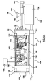
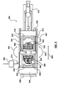
- FIGS. 1A to 1E are side-elevation views of a system 100 according to the first exemplary embodiment (which is the preferred embodiment).
- the elements or components of the system 100 may be supplied by different vendors in different combinations and permutations or may be supplied by a single vendor.
- the system 100 includes a mold-moving assembly 102 that cooperates with an insert-forming station 108 to form an insert (at least in part) and cooperates with an overmolding station 110 to overmold the formed insert.
- the mold-moving assembly 102 is used to move an insert (114; 214; 514) between the insert-forming station 108 and the overmolding station 110.
- Operation of the insert-forming station 108 and operation of the overmolding station 110 overlap one another at least in part so that a reduction in cycle time is achieved.
- the operation of the insert-forming station 108 and operation of the molding station 110 occur simultaneously or near simultaneously (that is, overlap of operations occur concurrently) for best possible reduction in cycle time.
- Other technical effects are reduced floor space used by the system 100, reduced capital cost to purchase the system 100, reduced auxiliary operations, and/or improved production yield (all at least in part).
- a set of mold halves (104, 106) is attached to the mold-moving assembly 102.
- the set of mold halves (104, 106) includes a mold half 104 and a mold half 106.
- the mold halves 104, 106 are depicted as a core side of a mold.
- the mold-moving assembly 102 moves the set of mold halves (104, 106) between the insert-forming station 108 and the overmolding station 110.
- the insert-forming station 108 is used to form or shape an insert 114.
- the insert 114 is releasably retained by the mold half 104.
- the overmolding station 110 is used to overmold a formed insert 118 that was previously formed by the insert-forming station 108.
- the formed insert 118 is releasably retained by the mold half 106.
- a rotation actuator (not depicted) is included with the mold-moving assembly 102 and is actuated to cause the assembly 102 to rotate the set of mold halves (104, 106) about a horizontally-aligned rotation axis.
- the mold-moving assembly 102 has rotated the mold half 104 into the insert-forming station 108 and has rotated the mold half 106 into the overmolding station 110.
- a pair of stroke actuators 113 is used to stroke (that is, linearly translate) the mold-moving assembly 102 toward and away from the station 110 along a base 111 that rests on a factory floor.
- Another pair of stroke actuators (not depicted because they are behind the actuators 113 in this view) is also used to stroke the mold-moving assembly 102 away and toward the station 110. Movement of the mold moving assembly 102 is depicted as horizontally aligned.
- a group of mold halves (104, 106, 112) is used in the insert-forming station 108.
- the group of mold halves (104, 106, 112) includes the mold half 104, the mold half 106 and a mold half 112.
- the mold half 112 is depicted as the cavity side of a mold.
- the group of mold halves (104, 106, 112) shares at least one mold half in common with the set of mold halves (104, 106).
- the mold half 112 and the mold half 104 are used in the process of forming the insert 114.
- the insert 114 includes a metallic hollow body, and the insert-forming station 108 is used to hydro-form the insert 114. Hydro-forming of the insert 114 may be done in a number of conventionally acceptable approaches, such as using a bladder (for example) to form the insert 114.
- the insert-forming station 108 includes a movable platen 140, and the mold half 112 is attached to the movable platen 140.
- a platen-stroke actuator 141 is attached to the stationary platen 132 and is also attached to the movable platen 140.
- the actuator 141 is used to stroke (or linearly translate) the movable platen 140 along the base 111 toward and away from the mold moving assembly 102 so that the mold half 112 may be closed or opened relative to the mold half 104.
- Another platen-stroke actuator (not depicted because it is hidden behind the tie bar in this view) is also used to stroke the movable platen 140 toward and away from the mold moving assembly 102.
- a collection of mold halves (104, 106, 116) is used in the overmolding station 110.
- the collection of mold halves (104, 106, 116) includes the mold half 104, the mold half 106 and a mold half 116.
- the mold half 116 is depicted as the cavity side of mold.
- the collection of mold halves (104, 106, 116) shares at least one mold half in common with the set of mold halves (104, 106).
- the mold half 116 and the mold half 106 are used to overmold a molding material on the formed insert 118 that is retained by the mold half 106.
- the formed insert 118 was previously formed in the insert-forming station 108.
- the overmolding station 110 includes the stationary platen 132, and the mold half 116 is attached to the stationary platen 132.
- the actuators 113 stroke the mold-moving assembly 102 so that the mold half 116 may be closed or opened relative to the mold half 106.
- the mold-moving assembly 102 is actuated to rotate the insert 114 that was formed in the insert-forming station 108 over to the overmolding station 110 so that the overmolding station 110 may subsequently overmold or encapsulate a molding material relative to the insert 114.
- the molding material is overmolded relative to a gripping feature (or a surface feature) of the formed insert 118 that is retained by the mold half 106.
- the gripping feature may be a hole defined by the insert 118 or may be a pin or set of pins extending from the insert 118, etc.
- the gripping feature permits the overmolded material to better grip (and become better integrated with) the inset 118.
- the molding material frictionally engages the insert 118. It will be appreciated that the cavity and the core sides of the mold halves identified above are interchangeable.
- An insert-delivery mechanism 120 delivers and places the insert 114 into the insert-forming station 108, and preferably places the insert 114 on a surface of the mold half 104.
- the mold half 104 retains the insert 114, and then the insert-delivery mechanism 120 retracts from the insert-forming station 108 so that the insert 114 may be formed in the station 108.
- Extending between the stationary platen 132 and the movable platen 140 is a set of four tie bars 136, 138 (two of which are hidden behind tie bars 136, 138 in this view).
- a tie-bar support structure 139 is used to prevent the tie bars 136, 138 from sagging.
- the tie bars 136, 138 are fixedly attached to the stationary platen 132, extend through the movable platen 140 and over to the tie-bar support structure 139.
- the movable platen 140 is slidable along the tie bars 136, 138.
- a clamping assembly 135 is placed in the movable platen 140 and is used to apply a mold clamping force (via the tie bars 136, 138) for clamping up mold halves and to apply a mold-break force for breaking apart mold halves.
- the clamping assembly includes, for example, a pineapple-style clamping mechanism as known in the art.
- the stroke actuators 113 are used to stroke the mold-moving assembly 102 to close the mold halves 106, 116 together.
- the stroke actuator 141 is used to stroke the movable platen 140 toward the stationary platen 132 to close the mold halves 104, 112 together.
- the clamping mechanism is actuated to apply the clamping force (via the tie bars 136, 138) that acts to clamp up the closed mold halves.
- the clamping force via the tie bars 136, 138
- the formed insert 118 is overmolded in the overmolding station 110 and the insert 114 is formed in the insert-forming station 108.
- the clamping assembly applies the mold break force to break apart the mold halves; then the actuators 113, 141 actuate to separate the mold halves apart from each other.
- the overmolding station 110 includes an injection unit 122.
- the injection unit 122 includes an injection unit base 124, and includes a barrel assembly 126 that is attached to the injection unit base 124. Attached to the barrel assembly 126 is a hopper 128.
- the barrel assembly 126 defines an internal chamber that is sized to receive a processing screw (not depicted) that is used to process a molding material. Disposed at a tip of the barrel assembly 126 is a nozzle 130.
- the nozzle 130 dispenses the molding material into a sprue (not depicted) that is disposed in the stationary platen 132 and the sprue is connected to a passageway defined by the mold half 116.
- the sprue conveys the molding material over to a cavity defined by the mold halves 106, 116 or to a cavity defined by the mold halves 104, 116 during an injection cycle of the injection unit 122.
- a screw-control mechanism 134 rotates and/or translates, when actuated, the processing screw according to manufacturing criteria and/or molding material criteria.
- a molding material (such as, for example, a plastic resin or a magnesium alloy) is introduced into the hopper 128, which then feeds the molding material to the barrel assembly 126.
- the processing screw processes the molding material into a suitable state, then moves the molding material along the barrel assembly 126 toward the mold half 116.
- the mold half 106 Before initiation of the injection cycle of the injection unit 122, the mold half 106 is closed and clamped up against the mold half 116. During the injection cycle, the nozzle 130 is opened and the processing screw moves to force the molding material out from the barrel assembly 126 through the opened nozzle, into the sprue, then into the mold cavity defined by the mold halves 106, 116. Since the mold half 106 retains the formed insert 118 within the mold cavity, the molding material is overmolded on the insert 118.
- a technical effect of the molding system 100 is, amongst other things, a reduction of cycle time for manufacturing overmolded, formed inserts.
- FIG. 1B depicts the insert-delivery mechanism 120 having transferred the insert 114 over to the mold half 104, and the mold half 104 retains the insert 114.
- the mold half 104 includes a vacuum line 142 that uses negative pressure to releasably retain or to hold the insert 114.
- Embodiments for releasably holding or retaining the insert 114 to the mold half 104 are depicted in FIGS. 3A to 3D .
- FIG. 1C depicts the moving platen 140 and the moving-mold assembly 102 actuated to move toward the stationary platen 132 so that the mold half 104 becomes closed against the mold half 112, and so that the mold half 106 becomes closed against the mold half 116.
- the mold halves of the mold-moving assembly 102, the insert-forming station 108 and the overmolding station 110 may be opened and closed concurrently or independently of each other. Once the mold halves 104, 112 are closed together in the insert-forming station 108, a hydro-forming process is performed on the insert 114.
- a high-pressure fluid such as oil, water, etc.
- a high-pressure fluid is injected into the hollow insert 114 with sufficient pressure so that the insert 114 becomes deformed and adopts a shape, at least in part, that is defined by the mold surfaces of the mold halves 104, 112.
- the hollow insert 114 may have a fluid conduit extending from the insert 114 so that the hydro-forming process may be performed.
- the insert 114 may be provided with an orifice that mates directly to a nozzle (not depicted) that extends from the mold half 104 for connection to a hydro-forming fluid supply (not depicted). Once the insert 114 is hydro-formed, the fluid may be drained from the insert 114.
- the insert 114 is formed by pressing the mold halves 104, 112 together without the use of a hydro-forming fluid.
- a non-hydro forming process is used to form or shape the insert 114, and the insert 114 may be a solid body or a hollow body.
- a molding material is injected into a cavity that is defined by the mold halves 106, 116, and the molding material overmolds the insert 118 to form a composite article 150 (herafter called the "article" 150).
- Overmolding of the insert 118 may include molding a material onto and/or into the insert 118.
- the molding material may partially encapsulate or adhere to the insert 118 that is retained by the mold half 106.
- a vacuum may be actuated via a vacuum line 144 for retaining the insert 118.
- the insert-delivery mechanism 120 is depicted positioning a new insert 146 that is ready for insertion in the station. 108.
- FIG. 1D depicts the moving platen 140 and the moving-mold assembly 102 moved away from the stationary platen 132 so that the mold halves 104, 112 become separated from each other, and the mold halves 106, 116 become separated from each other. Then the mold-moving assembly 102 rotates the mold halves 104, 106 one hundred and eighty degrees so that the mold half 104 and the mold half 106 are rotated to face the mold half 116 and the mold half 112 respectively. During rotation, the mold half 104 retains the insert 114 while the mold half 106 retains the article 150.
- FIG. 1E depicts the mold half 104 facing the mold half 116, and depicts the mold half 106 facing the mold half 112.
- the article 150 is ejected from the mold half 106, and the insert-delivery mechanism 120 may place the new insert 146 onto the mold half 106.
- the insert 114 is ready to be overmolded with a molding material. The cycle of the molding system 100 may be repeated.
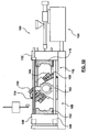
- FIG. 2 is a side-elevation view of a system 200 according to the second exemplary embodiment.
- the elements or components of the system 200 may be supplied by different vendors in different combinations and permutations or may be supplied by a single vendor.
- elements of the second embodiment (that are similar to those of the first embodiment) are identified by reference numerals that use a two-hundred designation rather than a one-hundred designation (as used in the first embodiment).
- the mold-moving assembly 202 of the second embodiment is labeled 202 rather than being labeled 102.
- the mold-moving assembly 202 translates mold halves 204, 206 along a vertically-aligned axis 201 in sharp contrast to the mold-moving assembly 102 that translates the mold halves 104, 106 along a horizontally-aligned axis.
- the system 200 operates in a manner that is similar to that of the system 100.
- FIGS. 3A to 3D are side-elevation views of the mold half 104 of the system 100 of FIG. 1A .
- the mold halves 104, 106 include a retaining structure 301 configured to retain or to hold, when actuated, an insert against a mold surface of a mold half.
- the mold-moving assembly 102 includes the retaining structure.
- FIG. 3A depicts an embodiment of the mold half 104 that includes a vacuum line 302 that is adapted to retain the insert 114 against the mold half 104.
- FIG. 3B depicts another embodiment of the mold half 104 that includes an electromagnet 304 that is adapted to hold the insert 114 against the mold half 104.
- FIGS. 3C and 3D depict yet another embodiment of the mold half 104 that includes a mechanical gripper 306 that is adapted to grab the insert 114 and to retain the insert 114 against the mold half 104.
- the gripper 306 is conventional and known.
- FIG. 3C dhows the gripper 306 extended and
- FIG. 3D shows the gripper retracted.
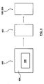
- FIG. 4 shows a block schematic diagram of an article of manufacture 400, according to the third embodiment, the article 400 for directing a data processing system 402 to control the system 100, 200 of FIGS. 1A and 2 respectively.
- the system 100, 200 is operatively connectable to the data processing system 402.
- the article of manufacture 400 includes a data processing system usable medium 404 embodying one or more instructions 406 executable by the data processing system 402.
- the article of manufacture 400 may be a magnetic disk; an optical disk, a hard drive or RAM (Random Access Memory).
- the article of manufacture 400 may also be a signal that carries the one or more instructions over a network, such as the Internet, to the data processing system 402.
- the one or more instructions 406 includes instructions for directing the data processing system to direct a mold-moving assembly 102, 202 to cooperate with an insert-forming station 108, 208 to form an insert, cooperate with an overmolding station 110, 210 to overmold another insert previously formed by the insert-forming station 108, 208 in cooperation with the mold-moving assembly 102, 202.
- the instructions also include instructions for directing the data processing system to direct operation of the mold-moving assembly 102, 202 to move an insert (114; 214; 514) between the insert-forming station 108, 208 and the overmolding station 110, 210.
- the instructions also include instructions for directing the data processing system to direct operation of the insert-forming station 108, 208 and operation of the overmolding station 110, 210 to overlap one another at least in part to reduce cycle time.
- the one or more instructions 406 also includes, but is not limited to, the following (in no particular order):
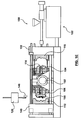
- FIG. 5 is a top-elevation view (looking downwardly) of a system 500 according to the fourth exemplary embodiment.
- the elements or components of the system 500 may be supplied by different vendors in different combinations and permutations or may be supplied by a single vendor.
- elements of the fourth embodiment (that are similar to those of the first embodiment) are identified by reference numerals that use a five-hundred designation rather than a one-hundred designation (as used in the first exemplary embodiment).
- the mold-moving assembly 502 of the fifth exemplary embodiment is labeled 502 rather than being labeled 102, etc.
- the mold-moving assembly 502 translates mold halves 504, 506 along a horizontally-aligned axis 505 (in a similar fashion to that of the system 100 of FIG. 1A ). However, the mold-moving assembly 502 rotates the mold halves 504, 506 about curved arrows 503 so that the mold halves 504, 506 are rotatable about a vertically-aligned axis that extends upwardly (it extends upwardly from the surface of FIG. 5 ); in sharp contrast, the mold-moving assembly 102 of FIG. 1A rotates the mold halves 104, 106 along a horizontally-aligned axis that extends upwardly from the surface of FIG. 1A . Other than that difference, the system 500 operates in a manner that is similar to that of the system 100.
- FIGS. 3A to 3D are also used with the system 500. It will be appreciated that the article of manufacture 400 of FIG. 4 is also used for controlling operation of the system 500 as well.
Abstract
Description
- The present invention generally relates to a system for overmolding an insert.
-
WO Patent Number 2004/011315 (Inventor: Staargaard et al ; Assignee: General Electric Company, USA),WO Patent Number 2004/056610 (Inventor: Staargaard; Assignee: General Electric Company, USA) andUS Patent Application Number 2003/0077409 (Inventor: Schnell) all appear to disclose a process and system for inserting a hydro-formed metal insert into a mold of a molding machine, and then partially encapsulating or overmolding the formed insert with a molding material (such as a plastic resin). This approach includes using different types of machines, one type for forming and another type for molding. - European Patent Number
826,476 (Inventor: Buchholz - An article titled Secondary Operations: Unique System Uses Press Motion As Punch and Die (published by Plastics World in September 1992, page 10) appears to disclose a molding system having a mold. With the mold opened, a press operator loads a metal insert (that is a metal buss bar) into the mold. As a press closes and clamps, a punch and die mechanism pierces a slug in the insert, and then a nylon-based molding material is injected into the mold to overmold the insert. The forming operation and the overmolding operation are performed sequentially (serially) in the same mold.
- A document (dated October 1989, titled ALPHA - Multi-processing Technology and published by Krauss Maffei of Germany), appears to disclose the ALPHA molding system that appears to be an integration of several types of molding systems (such as, for example, a compression molding system, an injection molding system and/or a gas-pressure molding system). This arrangement appears to combine different molding materials into a molded article using different processes.
- German Patent Number
1,130,155 (Inventor: Voumard et al ; Assignee: Regoma Company Limited) appears to disclose a process for joining or welding a tube head to a tube body. An injection mold uses a sprue channel for injection of plasticized resin. The sprue channel serves to create the tube head and it is designed as an annular passage or as a ring of closely adjacent boreholes, which feeds directly into the vicinity of a connection site that welds the tube head and the tube body in a molding chamber. The plasticized resin is fed under pressure into the channel and completely fills the space intended for the tube head so that in this manner the tube head is formed and simultaneously welded to the end of the tube body of the preform. Apparently, it is required to avoid pronounced cooling of the plasticized resin before it reaches the welding site to avoid jeopardizing secured welding of the tube body with the tube head. It appears that the tube head must be welded to a tube body so that when the tube body is manually depressed, the contents (such as toothpaste, for example) will not egress from the weld line but will egress from the opening defined in the tube head. This process appears to be a serial execution of operational steps. - German patent
10326768A1 (Assignee: BASF, dated 2004-01-22) teaches a procedure for the production of a hybrid device (27) from metallic material and from plastic material during a combined IHU Spritzgiess process. - A document (dated 1998-02-01, titled TOOL FORMS DEEP-DRAW METAL INSERT DURING INJECTION CYCLE and published by Modern Plastics International, vol 28. no. 2, page 30) teaches a machine where a metal insert is formed in the left-hand cavity of a double day-light mold, then transferred to the right-hand of the injection mold. The central platen holds two mold halves.
- German patent
19949263A1 (Assignee: Bayerische Motoren Werke AG, dated 2001-04-19) teaches A single tool is used for all process stages which involve: (a) cutting out a basic preform shape (2) from flat material (1); (b) heating the preform; (c) pressing the preform; and (d) cooling the preform prior to demolding. - German patent
10034518C1 (Assignee: Tsai Huo Lu, dated 2000-07-15) teaches A procedure for manufacturing keyboard buttons (30) covers the steps of the thermal pressure figuration of a thermoplastic plate (10) with a printed on layer (101) in a form recess (110, 120) of form equipment by means of one stamp (210), installed in the form equipment, in order to form an outside bowl (10 '), the rotation of the form equipment, in order to align the form recess (110, 120) with a resin spraying unit (240) aligning, which is installed in the form equipment, and injecting a resin into the form recess (110, 120) by means of the resin spraying unit (240), in order to form an internal bowl (20), those with the outside bowl (10 ') is stuck together and surrounded by this, whereby the printed on layer (101) between the inside bowl (20) and the thermoplastic plate (10) - Japanese patent
2006027138A - In an aspect of the present invention, there is provided a system, according to the features of claim 1.
- A technical effect is, amongst other things, a reduction in cycle time for overmolding inserts with molding material (that is, operation of the insert-forming station and operation of the overmolding station overlap one another at least in part).
- A better understanding of the exemplary embodiments of the present invention (including alternatives and/or variations thereof) may be obtained with reference to the detailed description of the exemplary embodiments along with the following drawings, in which:
-
FIGS. 1A to 1E are side-elevation views of a system according to a first exemplary embodiment; -
FIG. 2 is a side-elevation view of a system according to a second exemplary embodiment; -
FIGS. 3A to 3D are side-elevation views of a mold used in the system ofFIG. 1A or used in the system of FIG. 2A; -
FIG. 4 shows a block schematic diagram of an article of manufacture, according to a third embodiment, the article for directing a data processing system to control the systems ofFIGS. 1A and2 ; and -
FIG. 5 is a top-elevation view (looking downwardly) of a system according to a fourth exemplary embodiment. - The drawings are not necessarily to scale and are sometimes illustrated by phantom lines, diagrammatic representations and fragmentary views. In certain instances, details that are not necessary for an understanding of the embodiments or that render other details difficult to perceive may have been omitted.
-
FIGS. 1A to 1E are side-elevation views of asystem 100 according to the first exemplary embodiment (which is the preferred embodiment). The elements or components of thesystem 100 may be supplied by different vendors in different combinations and permutations or may be supplied by a single vendor. - The
system 100 includes a mold-movingassembly 102 that cooperates with an insert-formingstation 108 to form an insert (at least in part) and cooperates with anovermolding station 110 to overmold the formed insert. The mold-movingassembly 102 is used to move an insert (114; 214; 514) between the insert-formingstation 108 and theovermolding station 110. Operation of the insert-formingstation 108 and operation of theovermolding station 110 overlap one another at least in part so that a reduction in cycle time is achieved. Preferably, if possible, the operation of the insert-formingstation 108 and operation of themolding station 110 occur simultaneously or near simultaneously (that is, overlap of operations occur concurrently) for best possible reduction in cycle time. Other technical effects are reduced floor space used by thesystem 100, reduced capital cost to purchase thesystem 100, reduced auxiliary operations, and/or improved production yield (all at least in part). - A set of mold halves (104, 106) is attached to the mold-moving
assembly 102. The set of mold halves (104, 106) includes amold half 104 and amold half 106. Themold halves assembly 102 moves the set of mold halves (104, 106) between the insert-formingstation 108 and theovermolding station 110. The insert-formingstation 108 is used to form or shape aninsert 114. Theinsert 114 is releasably retained by themold half 104. Theovermolding station 110 is used to overmold a formedinsert 118 that was previously formed by the insert-formingstation 108. The formedinsert 118 is releasably retained by themold half 106. - A rotation actuator (not depicted) is included with the mold-moving
assembly 102 and is actuated to cause theassembly 102 to rotate the set of mold halves (104, 106) about a horizontally-aligned rotation axis. As depicted inFIG. 1A , the mold-movingassembly 102 has rotated themold half 104 into the insert-formingstation 108 and has rotated themold half 106 into theovermolding station 110. A pair ofstroke actuators 113 is used to stroke (that is, linearly translate) the mold-movingassembly 102 toward and away from thestation 110 along a base 111 that rests on a factory floor. Another pair of stroke actuators (not depicted because they are behind theactuators 113 in this view) is also used to stroke the mold-movingassembly 102 away and toward thestation 110. Movement of themold moving assembly 102 is depicted as horizontally aligned. - A group of mold halves (104, 106, 112) is used in the insert-forming
station 108. The group of mold halves (104, 106, 112) includes themold half 104, themold half 106 and amold half 112. Themold half 112 is depicted as the cavity side of a mold. The group of mold halves (104, 106, 112) shares at least one mold half in common with the set of mold halves (104, 106). Themold half 112 and themold half 104 are used in the process of forming theinsert 114. Preferably, theinsert 114 includes a metallic hollow body, and the insert-formingstation 108 is used to hydro-form theinsert 114. Hydro-forming of theinsert 114 may be done in a number of conventionally acceptable approaches, such as using a bladder (for example) to form theinsert 114. - The insert-forming
station 108 includes amovable platen 140, and themold half 112 is attached to themovable platen 140. A platen-stroke actuator 141 is attached to thestationary platen 132 and is also attached to themovable platen 140. Theactuator 141 is used to stroke (or linearly translate) themovable platen 140 along the base 111 toward and away from the mold moving assembly 102 so that themold half 112 may be closed or opened relative to themold half 104. Another platen-stroke actuator (not depicted because it is hidden behind the tie bar in this view) is also used to stroke themovable platen 140 toward and away from themold moving assembly 102. - A collection of mold halves (104, 106, 116) is used in the
overmolding station 110. The collection of mold halves (104, 106, 116) includes themold half 104, themold half 106 and amold half 116. Themold half 116 is depicted as the cavity side of mold. The collection of mold halves (104, 106, 116) shares at least one mold half in common with the set of mold halves (104, 106). Themold half 116 and themold half 106 are used to overmold a molding material on the formedinsert 118 that is retained by themold half 106. The formedinsert 118 was previously formed in the insert-formingstation 108. Theovermolding station 110 includes thestationary platen 132, and themold half 116 is attached to thestationary platen 132. Theactuators 113 stroke the mold-movingassembly 102 so that themold half 116 may be closed or opened relative to themold half 106. The mold-movingassembly 102 is actuated to rotate theinsert 114 that was formed in the insert-formingstation 108 over to theovermolding station 110 so that theovermolding station 110 may subsequently overmold or encapsulate a molding material relative to theinsert 114. The molding material is overmolded relative to a gripping feature (or a surface feature) of the formedinsert 118 that is retained by themold half 106. The gripping feature may be a hole defined by theinsert 118 or may be a pin or set of pins extending from theinsert 118, etc. The gripping feature permits the overmolded material to better grip (and become better integrated with) theinset 118. Alternatively, the molding material frictionally engages theinsert 118. It will be appreciated that the cavity and the core sides of the mold halves identified above are interchangeable. - An insert-
delivery mechanism 120 delivers and places theinsert 114 into the insert-formingstation 108, and preferably places theinsert 114 on a surface of themold half 104. Themold half 104 retains theinsert 114, and then the insert-delivery mechanism 120 retracts from the insert-formingstation 108 so that theinsert 114 may be formed in thestation 108. - Extending between the
stationary platen 132 and themovable platen 140 is a set of fourtie bars 136, 138 (two of which are hidden behind tie bars 136, 138 in this view). A tie-bar support structure 139 is used to prevent the tie bars 136, 138 from sagging. The tie bars 136, 138 are fixedly attached to thestationary platen 132, extend through themovable platen 140 and over to the tie-bar support structure 139. Themovable platen 140 is slidable along the tie bars 136, 138. A clampingassembly 135 is placed in themovable platen 140 and is used to apply a mold clamping force (via the tie bars 136, 138) for clamping up mold halves and to apply a mold-break force for breaking apart mold halves. The clamping assembly includes, for example, a pineapple-style clamping mechanism as known in the art. The stroke actuators 113 are used to stroke the mold-movingassembly 102 to close the mold halves 106, 116 together. Thestroke actuator 141 is used to stroke themovable platen 140 toward thestationary platen 132 to close the mold halves 104, 112 together. Once the mold halves are closed together then the clamping mechanism is actuated to apply the clamping force (via the tie bars 136, 138) that acts to clamp up the closed mold halves. Once the mold halves are clamped up, the formedinsert 118 is overmolded in theovermolding station 110 and theinsert 114 is formed in the insert-formingstation 108. Once thestations actuators - The
overmolding station 110 includes aninjection unit 122. Theinjection unit 122 includes aninjection unit base 124, and includes abarrel assembly 126 that is attached to theinjection unit base 124. Attached to thebarrel assembly 126 is ahopper 128. Thebarrel assembly 126 defines an internal chamber that is sized to receive a processing screw (not depicted) that is used to process a molding material. Disposed at a tip of thebarrel assembly 126 is anozzle 130. Thenozzle 130 dispenses the molding material into a sprue (not depicted) that is disposed in thestationary platen 132 and the sprue is connected to a passageway defined by themold half 116. The sprue conveys the molding material over to a cavity defined by the mold halves 106, 116 or to a cavity defined by the mold halves 104, 116 during an injection cycle of theinjection unit 122. A screw-control mechanism 134 rotates and/or translates, when actuated, the processing screw according to manufacturing criteria and/or molding material criteria. A molding material (such as, for example, a plastic resin or a magnesium alloy) is introduced into thehopper 128, which then feeds the molding material to thebarrel assembly 126. The processing screw processes the molding material into a suitable state, then moves the molding material along thebarrel assembly 126 toward themold half 116. Before initiation of the injection cycle of theinjection unit 122, themold half 106 is closed and clamped up against themold half 116. During the injection cycle, thenozzle 130 is opened and the processing screw moves to force the molding material out from thebarrel assembly 126 through the opened nozzle, into the sprue, then into the mold cavity defined by the mold halves 106, 116. Since themold half 106 retains the formedinsert 118 within the mold cavity, the molding material is overmolded on theinsert 118. - A technical effect of the
molding system 100 is, amongst other things, a reduction of cycle time for manufacturing overmolded, formed inserts. -
FIG. 1B depicts the insert-delivery mechanism 120 having transferred theinsert 114 over to themold half 104, and themold half 104 retains theinsert 114. Themold half 104 includes avacuum line 142 that uses negative pressure to releasably retain or to hold theinsert 114. Embodiments for releasably holding or retaining theinsert 114 to themold half 104 are depicted inFIGS. 3A to 3D . -
FIG. 1C depicts the movingplaten 140 and the moving-mold assembly 102 actuated to move toward thestationary platen 132 so that themold half 104 becomes closed against themold half 112, and so that themold half 106 becomes closed against themold half 116. The mold halves of the mold-movingassembly 102, the insert-formingstation 108 and theovermolding station 110 may be opened and closed concurrently or independently of each other. Once the mold halves 104, 112 are closed together in the insert-formingstation 108, a hydro-forming process is performed on theinsert 114. For example, a high-pressure fluid (such as oil, water, etc.) is injected into thehollow insert 114 with sufficient pressure so that theinsert 114 becomes deformed and adopts a shape, at least in part, that is defined by the mold surfaces of the mold halves 104, 112. Thehollow insert 114 may have a fluid conduit extending from theinsert 114 so that the hydro-forming process may be performed. Alternatively, theinsert 114 may be provided with an orifice that mates directly to a nozzle (not depicted) that extends from themold half 104 for connection to a hydro-forming fluid supply (not depicted). Once theinsert 114 is hydro-formed, the fluid may be drained from theinsert 114. Fluid connections (for use in hydro-forming) to an insert are known and are not discussed here. Alternatively, theinsert 114 is formed by pressing the mold halves 104, 112 together without the use of a hydro-forming fluid. According to an alternative, a non-hydro forming process is used to form or shape theinsert 114, and theinsert 114 may be a solid body or a hollow body. - Once the mold halves 106, 116 are closed and clamped together, a molding material is injected into a cavity that is defined by the mold halves 106, 116, and the molding material overmolds the
insert 118 to form a composite article 150 (herafter called the "article" 150). Overmolding of theinsert 118 may include molding a material onto and/or into theinsert 118. The molding material may partially encapsulate or adhere to theinsert 118 that is retained by themold half 106. For example, a vacuum may be actuated via avacuum line 144 for retaining theinsert 118. The insert-delivery mechanism 120 is depicted positioning anew insert 146 that is ready for insertion in the station. 108. -
FIG. 1D depicts the movingplaten 140 and the moving-mold assembly 102 moved away from thestationary platen 132 so that the mold halves 104, 112 become separated from each other, and the mold halves 106, 116 become separated from each other. Then the mold-movingassembly 102 rotates the mold halves 104, 106 one hundred and eighty degrees so that themold half 104 and themold half 106 are rotated to face themold half 116 and themold half 112 respectively. During rotation, themold half 104 retains theinsert 114 while themold half 106 retains thearticle 150. -
FIG. 1E depicts themold half 104 facing themold half 116, and depicts themold half 106 facing themold half 112. Thearticle 150 is ejected from themold half 106, and the insert-delivery mechanism 120 may place thenew insert 146 onto themold half 106. Also, theinsert 114 is ready to be overmolded with a molding material. The cycle of themolding system 100 may be repeated. -
FIG. 2 is a side-elevation view of asystem 200 according to the second exemplary embodiment. The elements or components of thesystem 200 may be supplied by different vendors in different combinations and permutations or may be supplied by a single vendor. To facilitate an understanding of the second exemplary embodiment, elements of the second embodiment (that are similar to those of the first embodiment) are identified by reference numerals that use a two-hundred designation rather than a one-hundred designation (as used in the first embodiment). For example, the mold-movingassembly 202 of the second embodiment is labeled 202 rather than being labeled 102. - The mold-moving
assembly 202 translates mold halves 204, 206 along a vertically-alignedaxis 201 in sharp contrast to the mold-movingassembly 102 that translates the mold halves 104, 106 along a horizontally-aligned axis. Other than that difference, thesystem 200 operates in a manner that is similar to that of thesystem 100. -
FIGS. 3A to 3D are side-elevation views of themold half 104 of thesystem 100 ofFIG. 1A . The mold halves 104, 106 include a retainingstructure 301 configured to retain or to hold, when actuated, an insert against a mold surface of a mold half. According to an alternative embodiment, the mold-movingassembly 102 includes the retaining structure. -
FIG. 3A depicts an embodiment of themold half 104 that includes avacuum line 302 that is adapted to retain theinsert 114 against themold half 104. -
FIG. 3B depicts another embodiment of themold half 104 that includes anelectromagnet 304 that is adapted to hold theinsert 114 against themold half 104. -
FIGS. 3C and 3D depict yet another embodiment of themold half 104 that includes amechanical gripper 306 that is adapted to grab theinsert 114 and to retain theinsert 114 against themold half 104. Thegripper 306 is conventional and known.FIG. 3C dhows thegripper 306 extended andFIG. 3D shows the gripper retracted. -
FIG. 4 shows a block schematic diagram of an article ofmanufacture 400, according to the third embodiment, thearticle 400 for directing adata processing system 402 to control thesystem FIGS. 1A and2 respectively. Thesystem data processing system 402. The article ofmanufacture 400 includes a data processing systemusable medium 404 embodying one ormore instructions 406 executable by thedata processing system 402. The article ofmanufacture 400 may be a magnetic disk; an optical disk, a hard drive or RAM (Random Access Memory). The article ofmanufacture 400 may also be a signal that carries the one or more instructions over a network, such as the Internet, to thedata processing system 402. - The one or
more instructions 406 includes instructions for directing the data processing system to direct a mold-movingassembly station overmolding station station assembly assembly station overmolding station station overmolding station - The one or
more instructions 406 also includes, but is not limited to, the following (in no particular order): - (i) instructions for directing the data processing system to direct the insert-forming
station insert - (ii) instructions for directing the data processing system to direct the
overmolding station insert - (iii) instructions for directing the data processing system to direct the insert-forming
station insert mold halves - (iv) instructions for directing the data processing system to direct the insert-forming
station insert station mold halves mold halves - (v) instructions for directing the data processing system to direct the
overmolding station insert overmolding station mold halves - (vi) instructions for directing the data processing system to direct the
overmolding station insert overmolding station mold halves mold halves - (vii) instructions for directing the data processing system to direct the mold-moving
assembly mold halves station overmolding station - (viii) instructions for directing the data processing system to direct the mold-moving
assembly mold halves station overmolding station - (ix) instructions for directing the data processing system to direct a retaining
structure 301 of the set ofmold halves - (x) instructions for directing the data processing system to direct the insert-forming
station insert -
FIG. 5 is a top-elevation view (looking downwardly) of asystem 500 according to the fourth exemplary embodiment. The elements or components of thesystem 500 may be supplied by different vendors in different combinations and permutations or may be supplied by a single vendor. To facilitate an understanding of the fourth exemplary embodiment, elements of the fourth embodiment (that are similar to those of the first embodiment) are identified by reference numerals that use a five-hundred designation rather than a one-hundred designation (as used in the first exemplary embodiment). For example, the mold-movingassembly 502 of the fifth exemplary embodiment is labeled 502 rather than being labeled 102, etc. - The mold-moving
assembly 502 translates mold halves 504, 506 along a horizontally-aligned axis 505 (in a similar fashion to that of thesystem 100 ofFIG. 1A ). However, the mold-movingassembly 502 rotates the mold halves 504, 506 aboutcurved arrows 503 so that the mold halves 504, 506 are rotatable about a vertically-aligned axis that extends upwardly (it extends upwardly from the surface ofFIG. 5 ); in sharp contrast, the mold-movingassembly 102 ofFIG. 1A rotates the mold halves 104, 106 along a horizontally-aligned axis that extends upwardly from the surface ofFIG. 1A . Other than that difference, thesystem 500 operates in a manner that is similar to that of thesystem 100. - It will be appreciated that the retaining
structure 301 ofFIGS. 3A to 3D are also used with thesystem 500. It will be appreciated that the article ofmanufacture 400 ofFIG. 4 is also used for controlling operation of thesystem 500 as well. - The description of the exemplary embodiments provides examples of the present invention, and these examples do not limit the scope of the present invention. It is understood that the scope of the present invention is limited by the claims. The concepts described above may be adapted for specific conditions and/or functions, and may be further extended to a variety of other applications that are within the scope of the present invention. Having thus described the exemplary embodiments, it will be apparent that modifications and enhancements are possible without departing from the concepts as described. Therefore, what is protected by way of letters patent are limited only by the scope of the following claims:
Claims (11)
- A system (100; 200; 500), comprising:a mold-moving assembly (102; 202; 502) cooperative with an insert-forming station (108; 208; 508) to form an insert (114; 214; 514) at least in part, the mold-moving assembly (102; 202; 502) cooperative with an overmolding station (110; 210; 510) to overmold, at least in part, another insert previously formed by the insert-forming station (108; 208; 508) in cooperation with the mold-moving assembly (102; 202; 502),wherein the mold-moving assembly (102; 202; 502) is actuatable to move the insert (114; 214; 514) between the insert-forming station (108; 208; 508) and the overmolding station (110; 210; 510), andthe insert (114; 214; 514) includes a metallic body, andthe insert-forming station (108; 208; 508) is configured to:receive the insert (114; 214; 514) before the insert (114; 214; 514) is formed by the insert-forming station (108; 208; 508), andform the metallic body of the insert (114; 214; 514); andcharacterized in that the system (100; 200; 500) includes a first pair of stroke actuators (113, 213, 513) for operation of the overmolding station (110; 210; 510) and a second pair of stroke actuators (141; 241; 541) for operation of the insert-forming station (108; 208; 508).
- The system (100; 200; 500) of claim 1, wherein the insert-forming station (108; 208; 508) is configured to form the insert (114; 214; 514) at least in part, and wherein the overmolding station (110; 210; 510) is configured to encapsulate the insert (114; 214; 514), at least in part, with a molding material.
- The system (100; 200; 500) of claim 1, wherein the mold-moving assembly (102; 202; 502) is configured to move a set of mold halves (104, 106; 204, 206; 504, 506) between the insert-forming station (108; 208; 508) and the overmolding station (110; 210; 510), and wherein the set of mold halves (104, 106; 204, 206; 504, 506) is configured to cooperate with the insert-forming station (108; 208; 508) to form the insert (114; 214; 514) at least in part.
- The system (100; 200; 500) of claim 1, wherein the mold-moving assembly (102; 202; 502) is configured to move a set of mold halves (104, 106; 204, 206; 504, 506) between the insert-forming station (108; 208; 508) and the overmolding station (110; 210; 510), and wherein the insert-forming station (108; 208; 508) includes a group of mold halves (104, 106, 112; 204, 206, 212; 504, 506, 512) configured to cooperate with the set of mold halves (104, 106; 204, 206; 504, 506) to form the insert (114; 214; 514) at least in part.
- The system (100; 200; 500) of claim 1, wherein the mold-moving assembly (102; 202; 502) is configured to move a set of mold halves (104, 106; 204, 206; 504, 506) between the insert-forming station (108; 208; 508) and the overmolding station (110; 210; 510), and wherein the set of mold halves (104, 106; 204, 206; 504, 506) is configured to cooperate with the overmolding station (110; 210; 510) to encapsulate an insert (114; 214; 514) with a molding material relative to a gripping feature of the insert (114; 214; 514) that is retained by a mold half (104, 106; 204, 206; 504, 506) of the set of mold halves (104, 106; 204, 206; 504, 506).
- The system (100; 200; 500) of claim 1, wherein the mold-moving assembly (102; 202; 502) is configured to move a set of mold halves (104, 106; 204, 206; 504, 506) between the insert-forming station (108; 208; 508) and the overmolding station (110; 210; 510), and wherein the overmolding station (110; 210; 510) includes a collection of mold halves (104, 106, 116; 204, 206, 216; 504, 506, 516) configured to cooperate with the set of mold halves (104, 106; 204, 206; 504, 506) to overmold an insert (114; 214; 514), at least in part, with a molding material.
- The system (100; 200; 500) of claim 1, wherein the mold-moving assembly (102; 202; 502) is configured to rotate a set of mold halves (104, 106; 204, 206; 504, 506) between the insert-forming station (108; 208; 508) and the overmolding station (110; 210; 510).
- The system (100; 200; 500) of claim 1, wherein the first pair of stroke actuators (113, 213, 513) is configured to linearly translate a mold half from the set of mold halves (104, 106; 204, 206; 504, 506) attached to the mold-moving assembly (102; 202; 502) relative to a mold half (116; 216; 516) located at the overmolding station (110; 210; 510).
- The system (100; 200; 500) of claim 1, wherein the mold-moving assembly (102; 202; 502) is configured to move a set of mold halves (104, 106; 204, 206; 504, 506) between the insert-forming station (108; 208; 508) and the overmolding station (110; 210; 510), and wherein the set of mold halves (104, 106; 204, 206; 504, 506) includes a retaining structure (301) configured to releasably retain the insert.
- The system (100; 200; 500) of claim 1, wherein the insert (114; 214; 514) includes a metallic component, and wherein the insert-forming station (108; 208; 508) is configured to hydroform the metallic component of the insert (114; 214; 514) at least in part.
- The system (100; 200; 500) of claim 1, wherein the second pair of stroke actuators (141; 241; 541) is configured to linearly translate a mold half (112; 212; 512) located at the insert-forming station (108; 208; 508) towards a mold half from the set of mold halves (104, 106; 204, 206; 504, 506) attached to the mold-moving assembly (102; 202; 502).
Applications Claiming Priority (2)
| Application Number | Priority Date | Filing Date | Title |
|---|---|---|---|
| US11/373,203 US7313459B2 (en) | 2006-03-13 | 2006-03-13 | System for overmolding insert |
| PCT/CA2007/000157 WO2007104127A1 (en) | 2006-03-13 | 2007-02-05 | System for overmolding insert |
Publications (3)
| Publication Number | Publication Date |
|---|---|
| EP1996381A1 EP1996381A1 (en) | 2008-12-03 |
| EP1996381A4 EP1996381A4 (en) | 2009-04-15 |
| EP1996381B1 true EP1996381B1 (en) | 2012-01-04 |
Family
ID=38479988
Family Applications (1)
| Application Number | Title | Priority Date | Filing Date |
|---|---|---|---|
| EP07701754A Active EP1996381B1 (en) | 2006-03-13 | 2007-02-05 | System for overmolding an insert |
Country Status (8)
| Country | Link |
|---|---|
| US (2) | US7313459B2 (en) |
| EP (1) | EP1996381B1 (en) |
| CN (1) | CN101400497B (en) |
| AT (1) | ATE539868T1 (en) |
| BR (1) | BRPI0708743A2 (en) |
| CA (1) | CA2642646C (en) |
| TW (1) | TWI303204B (en) |
| WO (1) | WO2007104127A1 (en) |
Families Citing this family (9)
| Publication number | Priority date | Publication date | Assignee | Title |
|---|---|---|---|---|
| US20080012176A1 (en) * | 2006-07-13 | 2008-01-17 | Husky Injection Molding Systems Ltd. | Overmolding of molded articles |
| US7487007B2 (en) * | 2006-10-19 | 2009-02-03 | Husky Injection Molding Systems Ltd. | Overmolding system |
| US7950441B2 (en) | 2007-07-20 | 2011-05-31 | GM Global Technology Operations LLC | Method of casting damped part with insert |
| US7665984B2 (en) | 2007-12-14 | 2010-02-23 | Husky Injection Molding Systems Ltd. | Platen-linkage assembly of injection molding system |
| DE102010019625B4 (en) * | 2009-05-27 | 2017-08-24 | Engel Austria Gmbh | Method for producing a composite or hybrid construction |
| TW201529171A (en) | 2013-09-16 | 2015-08-01 | Graco Minnesota Inc | Spray tip and method of manufacture |
| DE112014004748T5 (en) * | 2013-10-16 | 2016-08-11 | Otto Männer Innovation GmbH | Injection molding and assembly apparatus and method for casting and assembling a plurality of two different castings |
| CN105965761B (en) * | 2016-07-01 | 2018-08-28 | 王静 | A kind of production equipment and its technique of balanced ring for washing machine |
| CN110625911A (en) * | 2019-09-09 | 2019-12-31 | 宁波方正汽车模具股份有限公司 | Automobile oil tank insert mounting mechanism |
Family Cites Families (18)
| Publication number | Priority date | Publication date | Assignee | Title |
|---|---|---|---|---|
| DE1130155B (en) | 1955-05-28 | 1962-05-24 | Regoma Company Ltd | Injection mold for injecting a tube head onto a prefabricated tubular tube blank made of thermoplastic material and forming the tube jacket |
| US4330257A (en) * | 1979-11-15 | 1982-05-18 | Husky Injection Molding Systems, Inc. | Turret-type injection-molding machine |
| US5087404A (en) | 1989-12-01 | 1992-02-11 | Ykk Corporation | Method for molding on carrier strip material |
| US5094601A (en) | 1989-12-01 | 1992-03-10 | Ykk Corporation | Apparatus for molding on carrier strip material |
| US5728409A (en) * | 1996-03-06 | 1998-03-17 | Husky Injection Molding Systems Ltd. | Turret article molding machine |
| US5797180A (en) | 1996-08-28 | 1998-08-25 | Tecumseh Products Company | Method of manufacturing a plastic camshaft with a tubular metal insert |
| US6322738B1 (en) | 1997-07-24 | 2001-11-27 | Husky Injection Molding Systems Ltd. | Method of injection over-molding articles |
| FR2777497B1 (en) | 1998-04-16 | 2000-05-19 | Fenec Sa | MACHINE FOR MANUFACTURING PARTS SUCH AS SKATES FOR FIXING UNDER THE LEGS OF FURNITURE |
| DE19949263A1 (en) | 1999-10-13 | 2001-04-19 | Bayerische Motoren Werke Ag | Plastic component manufacturing process uses a single tool to produce a molded product from flat sheet |
| DE10014332C2 (en) * | 2000-03-24 | 2002-03-14 | Basf Ag | Composite component and method for its production |
| DE10034518C1 (en) | 2000-07-15 | 2001-08-23 | Tsai Huo Lu | Methods of making keyboard buttons |
| DE10227636A1 (en) * | 2002-06-21 | 2004-01-15 | Krauss-Maffei Kunststofftechnik Gmbh | Method and device for producing multi-component molded plastic parts |
| DE10326768A1 (en) | 2002-06-28 | 2004-01-22 | Basf Ag | Combined internal high pressure forming and injection molding process for production of hybrid metal and plastic components involves hydroforming a sealed, fluid filled preform followed by plastic injection |
| EP1539538A4 (en) | 2002-07-25 | 2007-07-25 | Gen Electric | Method of attaching plastic to a metal section and part made thereby |
| JP2006510537A (en) | 2002-12-19 | 2006-03-30 | ゼネラル・エレクトリック・カンパニイ | Front-end module |
| JP2004345328A (en) * | 2003-05-26 | 2004-12-09 | Toshiba Mach Co Ltd | Vertical injection molding machine |
| JP4107593B2 (en) * | 2004-07-16 | 2008-06-25 | 日精樹脂工業株式会社 | Insert molding equipment |
| WO2006101631A2 (en) * | 2005-03-15 | 2006-09-28 | The Coca-Cola Company | Method of manufacturing overmolded containers, overmolded containers and preforms, and method for recycling an overmolded container |
-
2006
- 2006-03-13 US US11/373,203 patent/US7313459B2/en not_active Ceased
-
2007
- 2007-02-05 AT AT07701754T patent/ATE539868T1/en active
- 2007-02-05 CN CN2007800088383A patent/CN101400497B/en not_active Expired - Fee Related
- 2007-02-05 CA CA2642646A patent/CA2642646C/en not_active Expired - Fee Related
- 2007-02-05 BR BRPI0708743-8A patent/BRPI0708743A2/en not_active IP Right Cessation
- 2007-02-05 EP EP07701754A patent/EP1996381B1/en active Active
- 2007-02-05 WO PCT/CA2007/000157 patent/WO2007104127A1/en active Application Filing
- 2007-02-14 TW TW096105483A patent/TWI303204B/en not_active IP Right Cessation
-
2008
- 2008-09-25 US US12/204,221 patent/USRE42356E1/en not_active Expired - Fee Related
Also Published As
| Publication number | Publication date |
|---|---|
| EP1996381A1 (en) | 2008-12-03 |
| EP1996381A4 (en) | 2009-04-15 |
| CN101400497B (en) | 2011-10-12 |
| CA2642646C (en) | 2011-01-11 |
| CN101400497A (en) | 2009-04-01 |
| ATE539868T1 (en) | 2012-01-15 |
| US20070213868A1 (en) | 2007-09-13 |
| USRE42356E1 (en) | 2011-05-10 |
| TW200744818A (en) | 2007-12-16 |
| BRPI0708743A2 (en) | 2011-06-28 |
| US7313459B2 (en) | 2007-12-25 |
| CA2642646A1 (en) | 2007-09-20 |
| TWI303204B (en) | 2008-11-21 |
| WO2007104127A1 (en) | 2007-09-20 |
Similar Documents
| Publication | Publication Date | Title |
|---|---|---|
| EP1996381B1 (en) | System for overmolding an insert | |
| EP2083984B1 (en) | Method of operating an overmolding system | |
| US6517337B1 (en) | Injection molding machine having a modular construction which comprises a plurality of drive groups | |
| CA2654009C (en) | Overmolding of molded articles | |
| EP2019744B1 (en) | System for integrating insert with molded article | |
| JP5207298B2 (en) | COMPOSITE MOLDING APPARATUS AND TRANSFER APPARATUS FOR INTERMEDIATE MOLDED PRODUCT OF THE COMPOSITE MOLDING APPARATUS | |
| US6495077B1 (en) | Gate cut apparatus and method for a disc molding apparatus | |
| JP3304832B2 (en) | Multistage molding method and injection molding machine for hollow molded products | |
| JP4815397B2 (en) | Mold apparatus for molding flat molded article by injection compression molding and molding method thereof | |
| JP2010105168A (en) | Multi-material injection-molding apparatus, multi-material injection-molding method, and multi-material injection-molding mold | |
| JP3731811B2 (en) | Manufacturing method of synthetic resin molded products | |
| EP2216159A1 (en) | Ejection assemblies for injection moulding systems | |
| JP2005014317A (en) | Injection molding method and mold assembly | |
| KR100355741B1 (en) | Gate cut apparatus and method for a disc molding apparatus | |
| JPH081065Y2 (en) | Manufacturing equipment for cylindrical molded products | |
| JP2002307155A (en) | Die for metal injection molding | |
| JPH11300798A (en) | Injection molding device and injection molding process | |
| CN111331778A (en) | Method and apparatus for molding composite of insert and resin material | |
| JP2002028929A (en) | Mold attaching method for injection molding machine | |
| JP2009066844A (en) | Molded piece unloading device of injection-molding machine and molded piece unloading method |
Legal Events
| Date | Code | Title | Description |
|---|---|---|---|
| PUAI | Public reference made under article 153(3) epc to a published international application that has entered the european phase |
Free format text: ORIGINAL CODE: 0009012 |
|
| 17P | Request for examination filed |
Effective date: 20080925 |
|
| AK | Designated contracting states |
Kind code of ref document: A1 Designated state(s): AT BE BG CH CY CZ DE DK EE ES FI FR GB GR HU IE IS IT LI LT LU LV MC NL PL PT RO SE SI SK TR |
|
| AX | Request for extension of the european patent |
Extension state: AL BA HR MK RS |
|
| A4 | Supplementary search report drawn up and despatched |
Effective date: 20090316 |
|
| 17Q | First examination report despatched |
Effective date: 20090507 |
|
| GRAP | Despatch of communication of intention to grant a patent |
Free format text: ORIGINAL CODE: EPIDOSNIGR1 |
|
| RTI1 | Title (correction) |
Free format text: SYSTEM FOR OVERMOLDING AN INSERT |
|
| GRAS | Grant fee paid |
Free format text: ORIGINAL CODE: EPIDOSNIGR3 |
|
| GRAA | (expected) grant |
Free format text: ORIGINAL CODE: 0009210 |
|
| RAP1 | Party data changed (applicant data changed or rights of an application transferred) |
Owner name: HUSKY INJECTION MOLDING SYSTEMS LTD. |
|
| AK | Designated contracting states |
Kind code of ref document: B1 Designated state(s): AT BE BG CH CY CZ DE DK EE ES FI FR GB GR HU IE IS IT LI LT LU LV MC NL PL PT RO SE SI SK TR |
|
| AX | Request for extension of the european patent |
Extension state: AL BA HR MK RS |
|
| REG | Reference to a national code |
Ref country code: GB Ref legal event code: FG4D |
|
| REG | Reference to a national code |
Ref country code: CH Ref legal event code: EP |
|
| REG | Reference to a national code |
Ref country code: AT Ref legal event code: REF Ref document number: 539868 Country of ref document: AT Kind code of ref document: T Effective date: 20120115 |
|
| REG | Reference to a national code |
Ref country code: IE Ref legal event code: FG4D |
|
| REG | Reference to a national code |
Ref country code: DE Ref legal event code: R096 Ref document number: 602007019800 Country of ref document: DE Effective date: 20120308 |
|
| REG | Reference to a national code |
Ref country code: NL Ref legal event code: VDEP Effective date: 20120104 |
|
| PG25 | Lapsed in a contracting state [announced via postgrant information from national office to epo] |
Ref country code: SI Free format text: LAPSE BECAUSE OF FAILURE TO SUBMIT A TRANSLATION OF THE DESCRIPTION OR TO PAY THE FEE WITHIN THE PRESCRIBED TIME-LIMIT Effective date: 20120104 |
|
| LTIE | Lt: invalidation of european patent or patent extension |
Effective date: 20120104 |
|
| PG25 | Lapsed in a contracting state [announced via postgrant information from national office to epo] |
Ref country code: NL Free format text: LAPSE BECAUSE OF FAILURE TO SUBMIT A TRANSLATION OF THE DESCRIPTION OR TO PAY THE FEE WITHIN THE PRESCRIBED TIME-LIMIT Effective date: 20120104 Ref country code: BE Free format text: LAPSE BECAUSE OF FAILURE TO SUBMIT A TRANSLATION OF THE DESCRIPTION OR TO PAY THE FEE WITHIN THE PRESCRIBED TIME-LIMIT Effective date: 20120104 Ref country code: IS Free format text: LAPSE BECAUSE OF FAILURE TO SUBMIT A TRANSLATION OF THE DESCRIPTION OR TO PAY THE FEE WITHIN THE PRESCRIBED TIME-LIMIT Effective date: 20120504 Ref country code: LT Free format text: LAPSE BECAUSE OF FAILURE TO SUBMIT A TRANSLATION OF THE DESCRIPTION OR TO PAY THE FEE WITHIN THE PRESCRIBED TIME-LIMIT Effective date: 20120104 Ref country code: BG Free format text: LAPSE BECAUSE OF FAILURE TO SUBMIT A TRANSLATION OF THE DESCRIPTION OR TO PAY THE FEE WITHIN THE PRESCRIBED TIME-LIMIT Effective date: 20120404 |
|
| PG25 | Lapsed in a contracting state [announced via postgrant information from national office to epo] |
Ref country code: GR Free format text: LAPSE BECAUSE OF FAILURE TO SUBMIT A TRANSLATION OF THE DESCRIPTION OR TO PAY THE FEE WITHIN THE PRESCRIBED TIME-LIMIT Effective date: 20120405 Ref country code: PL Free format text: LAPSE BECAUSE OF FAILURE TO SUBMIT A TRANSLATION OF THE DESCRIPTION OR TO PAY THE FEE WITHIN THE PRESCRIBED TIME-LIMIT Effective date: 20120104 Ref country code: FI Free format text: LAPSE BECAUSE OF FAILURE TO SUBMIT A TRANSLATION OF THE DESCRIPTION OR TO PAY THE FEE WITHIN THE PRESCRIBED TIME-LIMIT Effective date: 20120104 Ref country code: LV Free format text: LAPSE BECAUSE OF FAILURE TO SUBMIT A TRANSLATION OF THE DESCRIPTION OR TO PAY THE FEE WITHIN THE PRESCRIBED TIME-LIMIT Effective date: 20120104 Ref country code: PT Free format text: LAPSE BECAUSE OF FAILURE TO SUBMIT A TRANSLATION OF THE DESCRIPTION OR TO PAY THE FEE WITHIN THE PRESCRIBED TIME-LIMIT Effective date: 20120504 |
|
| REG | Reference to a national code |
Ref country code: AT Ref legal event code: MK05 Ref document number: 539868 Country of ref document: AT Kind code of ref document: T Effective date: 20120104 |
|
| PG25 | Lapsed in a contracting state [announced via postgrant information from national office to epo] |
Ref country code: MC Free format text: LAPSE BECAUSE OF NON-PAYMENT OF DUE FEES Effective date: 20120229 Ref country code: CY Free format text: LAPSE BECAUSE OF FAILURE TO SUBMIT A TRANSLATION OF THE DESCRIPTION OR TO PAY THE FEE WITHIN THE PRESCRIBED TIME-LIMIT Effective date: 20120104 |
|
| PG25 | Lapsed in a contracting state [announced via postgrant information from national office to epo] |
Ref country code: CZ Free format text: LAPSE BECAUSE OF FAILURE TO SUBMIT A TRANSLATION OF THE DESCRIPTION OR TO PAY THE FEE WITHIN THE PRESCRIBED TIME-LIMIT Effective date: 20120104 Ref country code: DK Free format text: LAPSE BECAUSE OF FAILURE TO SUBMIT A TRANSLATION OF THE DESCRIPTION OR TO PAY THE FEE WITHIN THE PRESCRIBED TIME-LIMIT Effective date: 20120104 Ref country code: SE Free format text: LAPSE BECAUSE OF FAILURE TO SUBMIT A TRANSLATION OF THE DESCRIPTION OR TO PAY THE FEE WITHIN THE PRESCRIBED TIME-LIMIT Effective date: 20120104 Ref country code: RO Free format text: LAPSE BECAUSE OF FAILURE TO SUBMIT A TRANSLATION OF THE DESCRIPTION OR TO PAY THE FEE WITHIN THE PRESCRIBED TIME-LIMIT Effective date: 20120104 Ref country code: EE Free format text: LAPSE BECAUSE OF FAILURE TO SUBMIT A TRANSLATION OF THE DESCRIPTION OR TO PAY THE FEE WITHIN THE PRESCRIBED TIME-LIMIT Effective date: 20120104 |
|
| PLBE | No opposition filed within time limit |
Free format text: ORIGINAL CODE: 0009261 |
|
| STAA | Information on the status of an ep patent application or granted ep patent |
Free format text: STATUS: NO OPPOSITION FILED WITHIN TIME LIMIT |
|
| REG | Reference to a national code |
Ref country code: IE Ref legal event code: MM4A |
|
| PG25 | Lapsed in a contracting state [announced via postgrant information from national office to epo] |
Ref country code: SK Free format text: LAPSE BECAUSE OF FAILURE TO SUBMIT A TRANSLATION OF THE DESCRIPTION OR TO PAY THE FEE WITHIN THE PRESCRIBED TIME-LIMIT Effective date: 20120104 Ref country code: IT Free format text: LAPSE BECAUSE OF FAILURE TO SUBMIT A TRANSLATION OF THE DESCRIPTION OR TO PAY THE FEE WITHIN THE PRESCRIBED TIME-LIMIT Effective date: 20120104 |
|
| 26N | No opposition filed |
Effective date: 20121005 |
|
| PG25 | Lapsed in a contracting state [announced via postgrant information from national office to epo] |
Ref country code: IE Free format text: LAPSE BECAUSE OF NON-PAYMENT OF DUE FEES Effective date: 20120205 Ref country code: AT Free format text: LAPSE BECAUSE OF FAILURE TO SUBMIT A TRANSLATION OF THE DESCRIPTION OR TO PAY THE FEE WITHIN THE PRESCRIBED TIME-LIMIT Effective date: 20120104 |
|
| REG | Reference to a national code |
Ref country code: DE Ref legal event code: R097 Ref document number: 602007019800 Country of ref document: DE Effective date: 20121005 |
|
| PGFP | Annual fee paid to national office [announced via postgrant information from national office to epo] |
Ref country code: LU Payment date: 20130201 Year of fee payment: 7 |
|
| PG25 | Lapsed in a contracting state [announced via postgrant information from national office to epo] |
Ref country code: ES Free format text: LAPSE BECAUSE OF FAILURE TO SUBMIT A TRANSLATION OF THE DESCRIPTION OR TO PAY THE FEE WITHIN THE PRESCRIBED TIME-LIMIT Effective date: 20120415 |
|
| PGFP | Annual fee paid to national office [announced via postgrant information from national office to epo] |
Ref country code: FR Payment date: 20130222 Year of fee payment: 7 Ref country code: DE Payment date: 20130130 Year of fee payment: 7 Ref country code: GB Payment date: 20130131 Year of fee payment: 7 Ref country code: CH Payment date: 20130131 Year of fee payment: 7 |
|
| PG25 | Lapsed in a contracting state [announced via postgrant information from national office to epo] |
Ref country code: TR Free format text: LAPSE BECAUSE OF FAILURE TO SUBMIT A TRANSLATION OF THE DESCRIPTION OR TO PAY THE FEE WITHIN THE PRESCRIBED TIME-LIMIT Effective date: 20120104 |
|
| PG25 | Lapsed in a contracting state [announced via postgrant information from national office to epo] |
Ref country code: HU Free format text: LAPSE BECAUSE OF FAILURE TO SUBMIT A TRANSLATION OF THE DESCRIPTION OR TO PAY THE FEE WITHIN THE PRESCRIBED TIME-LIMIT Effective date: 20070205 |
|
| REG | Reference to a national code |
Ref country code: DE Ref legal event code: R119 Ref document number: 602007019800 Country of ref document: DE |
|
| PG25 | Lapsed in a contracting state [announced via postgrant information from national office to epo] |
Ref country code: LU Free format text: LAPSE BECAUSE OF NON-PAYMENT OF DUE FEES Effective date: 20140205 |
|
| REG | Reference to a national code |
Ref country code: CH Ref legal event code: PL |
|
| GBPC | Gb: european patent ceased through non-payment of renewal fee |
Effective date: 20140205 |
|
| PG25 | Lapsed in a contracting state [announced via postgrant information from national office to epo] |
Ref country code: CH Free format text: LAPSE BECAUSE OF NON-PAYMENT OF DUE FEES Effective date: 20140228 Ref country code: LI Free format text: LAPSE BECAUSE OF NON-PAYMENT OF DUE FEES Effective date: 20140228 |
|
| REG | Reference to a national code |
Ref country code: FR Ref legal event code: ST Effective date: 20141031 |
|
| REG | Reference to a national code |
Ref country code: DE Ref legal event code: R119 Ref document number: 602007019800 Country of ref document: DE Effective date: 20140902 |
|
| PG25 | Lapsed in a contracting state [announced via postgrant information from national office to epo] |
Ref country code: DE Free format text: LAPSE BECAUSE OF NON-PAYMENT OF DUE FEES Effective date: 20140902 Ref country code: FR Free format text: LAPSE BECAUSE OF NON-PAYMENT OF DUE FEES Effective date: 20140228 Ref country code: GB Free format text: LAPSE BECAUSE OF NON-PAYMENT OF DUE FEES Effective date: 20140205 |