EP1996012B1 - Elektronische haustiertrainiervorrichtung mit variabler spannung - Google Patents
Elektronische haustiertrainiervorrichtung mit variabler spannung Download PDFInfo
- Publication number
- EP1996012B1 EP1996012B1 EP06740089.5A EP06740089A EP1996012B1 EP 1996012 B1 EP1996012 B1 EP 1996012B1 EP 06740089 A EP06740089 A EP 06740089A EP 1996012 B1 EP1996012 B1 EP 1996012B1
- Authority
- EP
- European Patent Office
- Prior art keywords
- power converter
- controller
- training apparatus
- voltage
- electronic pet
- Prior art date
- Legal status (The legal status is an assumption and is not a legal conclusion. Google has not performed a legal analysis and makes no representation as to the accuracy of the status listed.)
- Active
Links
Images


Classifications
-
- A—HUMAN NECESSITIES
- A01—AGRICULTURE; FORESTRY; ANIMAL HUSBANDRY; HUNTING; TRAPPING; FISHING
- A01K—ANIMAL HUSBANDRY; AVICULTURE; APICULTURE; PISCICULTURE; FISHING; REARING OR BREEDING ANIMALS, NOT OTHERWISE PROVIDED FOR; NEW BREEDS OF ANIMALS
- A01K15/00—Devices for taming animals, e.g. nose-rings or hobbles; Devices for overturning animals in general; Training or exercising equipment; Covering boxes
- A01K15/02—Training or exercising equipment, e.g. mazes or labyrinths for animals ; Electric shock devices; Toys specially adapted for animals
- A01K15/021—Electronic training devices specially adapted for dogs or cats
-
- A—HUMAN NECESSITIES
- A01—AGRICULTURE; FORESTRY; ANIMAL HUSBANDRY; HUNTING; TRAPPING; FISHING
- A01K—ANIMAL HUSBANDRY; AVICULTURE; APICULTURE; PISCICULTURE; FISHING; REARING OR BREEDING ANIMALS, NOT OTHERWISE PROVIDED FOR; NEW BREEDS OF ANIMALS
- A01K27/00—Leads or collars, e.g. for dogs
- A01K27/009—Leads or collars, e.g. for dogs with electric-shock, sound, magnetic- or radio-waves emitting devices
Definitions
- the invention relates to an electronic animal training apparatus. More specifically, this invention relates to an electronic animal training apparatus using variable voltage stimulation.
- Pet correction collars using multiple corrective stimulation levels require both a method for controlling the stimulation level and when the stimulation is applied. Collar designs that are physically smaller and use lower operating voltages are no longer candidates for the use of traditional circuit topologies and components.
- Present implementations control the level of stimulation delivered by controlling the current, or activation level, or pulse width of the stimulation activation switch while maintaining a constant voltage to the primary winding of the high-voltage transformer.
- United States Patent 5,666,908 titled “Animal Training Device,” issued to So on September 16, 1997, discloses an animal training device that applies different levels of electrical stimulation to an animal by varying a pulse width.
- the electrical stimulation is generated by applying a series of pulses to a switch connected to a transformer, which has its secondary windings connected to electrodes that contact the animal.
- the pulses have a constant voltage level at a fixed frequency; however, the pulse widths vary based on the desired stimulation to be applied.
- the transformer secondary voltage is directly related to the pulse width, accordingly; the electrical stimulation applied to the animal varies as the voltage varies.
- the lowest level of stimulation is produced with narrow pulse widths resulting in a lower voltage of electrical stimulation applied to the animal.
- the highest level of stimulation is produced with wide pulse widths resulting in higher voltage of electrical stimulation.
- the Gonda device uses trains of pulses applied to the switch connected to the transformer.
- the Gonda device varies the stimulation intensity by varying the frequency of the pulses in the pulse train.
- the pulse train includes pulses having a fixed voltage and pulse width; however, the period between pulses is variable.
- the electrical stimulation applied to the animal is at a fixed voltage.
- the level of stimulation varies with the number of electrical stimulation signals applied to the animal per second. The lowest level of stimulation is produced by a pulse train with a low pulse frequency resulting in fewer electrical stimulation shocks per second. The highest level of stimulation is produced by a pulse train having a high pulse frequency resulting in more electrical stimulation shocks per second.
- the duration of the stimulation to the animal is controlled by the operator of the Gonda device.
- a still another example is the device disclosed in United States Patent Number 5,054,428 , titled “Method and Apparatus for Remote Conditioned Cue Control of Animal Training Stimulus,” issued to Farkus on October 8,1991.
- the Farkus device varies the stimulation intensity applied to the animal by varying the length of the pulse train applied to the switch connected to the transformer.
- the pulse train includes pulses having a fixed voltage and pulse width, and the pulses have a fixed frequency.
- the electrical stimulation applied to the animal is at a fixed voltage.
- the level of stimulation varies with the duration of the stimulation to the animal.
- the lowest level of stimulation is produced with a pulse train having a single pulse and a short duration.
- the highest level of stimulation is produced by a pulse train that includes approximately 64 pulses, which results in a longer duration stimulation being applied to the animal.
- US6166643 A discloses a radiofrequency signalling apparatus and method and to systems for controlling the whereabouts of pets or other animals by using radio frequency transmissions to establish boundaries for animals and by applying stimuli to the animals when they move into proximity of such a boundary to deter them from traversing it.
- the variable voltage electronic pet training apparatus includes a power supply in electrical communication with a voltage regulator.
- the voltage regulator provides a stable, regulated voltage to the controller.
- the controller generally controls the operation of the variable voltage electronic pet training apparatus based upon the imbedded control program.
- a power converter, a peak hold detector, a correction pulse switch, and an energy recovery circuit are in electrical communication with the controller.
- the power converter charges an energy storage capacitor.
- the controller sets the output voltage of the power converter.
- the optional peak hold detector tracks output of the power converter and keeps the maximum amplitude as a peak voltage on the energy storage capacitor. Feedback from the peak hold detector goes to the controller to allow the voltage of the power converter to be maintained at the desired level.
- An energy recovery circuit provides the ability to recover unspent energy from the energy storage capacitor.
- the controller drives the correction pulse switch and determines when the charge stored by the energy storage capacitor is applied to the primary of a transformer. When charge is applied to the primary transformer, the resulting voltage at the secondary is transferred to the animal through a pair of electrodes.
- a trigger circuit in communication with the controller is responsible for setting the desired intensity of the correction stimulus. The stimulus intensity is either set manually or automatically depending on the application.
- variable voltage electronic pet training apparatus is identified by the element number 100 in the text and the accompanying figures.
- the variable voltage electronic pet training apparatus controls the intensity of the stimulation by the controlling the voltage level present at the primary side of the transformer while maintaining a fixed control signal to the correction pulse switch.
- a trigger signal contains information about the desired stimulus intensity level.
- a controller interprets the trigger signal and produces a voltage control signal associated with the desired energy level.
- Application of the voltage control signal to a power converter keeps the voltage level applied to an energy storage capacitor sufficient to produce the desired stimulation intensity.
- FIG 1 is an illustration of one embodiment of the variable voltage electronic pet training apparatus 100.
- the variable voltage electronic pet training apparatus 100 includes an electronic training device 102 carried on a collar 104 worn by an animal 106 and a transmitter 108 that is in communication with the electronic training device 102.
- the variable voltage electronic pet training apparatus 100 is designed to deliver a mild electrical correction stimulus to the animal for the purpose of training or containment.
- the variable voltage electronic pet training apparatus 100 of the present invention provides the ability to alter the intensity of the correction stimulus based on a signal broadcast from the transmitter 108.
- variable voltage electronic pet training apparatus 100 can be worn on a strap or harness around other portions of the animal.
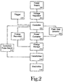
- FIG. 2 is a block diagram of the variable voltage electronic pet training apparatus 100.
- the variable voltage electronic pet training apparatus 100 includes a power supply 200 in electrical communication with a voltage regulator 202.
- the voltage regulator 202 provides a stable, regulated voltage to the controller 204.
- the controller 204 generally controls the operation of the variable voltage electronic pet training apparatus 100 based upon the imbedded control program.
- various control devices are available to implement the controller and will be selected based upon availability and desired functionality.
- a power converter 206, a peak hold detector 208, a correction pulse switch 210, and an energy recovery circuit 212 are in electrical communication with the controller 204.
- the power converter 206 charges an energy storage (correction) capacitor 214.
- the controller 204 sets the output voltage of the power converter 206.
- the optional peak hold detector 208 tracks output of the power converter 206 and keeps the maximum amplitude as a peak voltage on the energy storage capacitor 214. Feedback from the peak hold detector 208 goes to the controller to allow the voltage of the power converter 206 to be maintained at the desired level.
- An energy recovery circuit 212 provides the ability to recover unspent energy from the energy storage capacitor 214.
- the controller 204 drives the correction pulse switch 210 and determines when the charge stored by the energy storage capacitor is applied to the primary of a high voltage transformer 216.
- the resulting voltage at the secondary winding is transferred to the animal through a pair of electrodes 218.
- the resulting stimulus intensity is directly related to the voltage differential across the primary windings of the transformer 216 when the correction pulse switch 210 is activated with a fixed activation signal, i.e., an activation signal that does not vary in frequency, amplitude, or duration.
- the activation signal applied to the correction pulse switch 210 is a pulse train or similarly modified signal that allows precise control of the ON/OFF time for correction pulse switch 210 and allows improved efficiency when combined with the variable voltage technique of the present invention but is not necessary as the stimulus intensity is controlled by varying the voltage applied to the transformer.
- the correction pulse switch 210 is, generally, any device that can be controlled to efficiently turn on and off the application of a voltage to the primary windings of the transformer and is electrically sized for the voltage and current requirements. In certain embodiments, it is desirable for the correction pulse switch 210 to be a device responsive enough to allow rapid changes to the ON/OFF state so that precise control of the ON/OFF time can be achieved.
- the correction pulse switch may include one or multiple devices, which may be a discrete device (e.g., transistor, relay, etc) or a monolithic integrated device. The location of the correction pulse switch may be in either side of the transformer primary winding, source (high) or sink (low) side. The operation of the correction pulse switch may be as a discrete ON/OFF control or may include some other characteristic such as current limiting.
- the correction pulse switch control signal characteristics are matched with the correction pulse switch to produce the appropriate stimulation waveform desired.
- the power converter is any device that produces an output voltage by modifying the input voltage in such a manner that is corresponds to the characteristic of a power converter control signal.
- the power converter may be a discrete device, a monolithic integrated device such as an adjustable linear regulator or a switch-mode regulator that can attenuate or boost the input voltage to the desired voltage level.
- the variable voltage electronic pet training apparatus 100 uses the power converter control signal to create an appropriate control signal for the power converter to set the output voltage applied to the primary of the high-voltage transformer to produce the desired energy delivered to the secondary of the high voltage transformer, to the electrodes, and, ultimately, to the animal.
- the power converter control signal may be analog or digital, but is an appropriate signal to stimulate the power converter.
- Figure 2 includes a trigger circuit 220 in communication with the controller 204.
- the trigger circuit 220 is responsible for setting the desired intensity of the correction stimulus.
- the trigger circuit produces one or more signals that trigger a response by the controller 204 causing a correction stimulus of a desired intensity to be produced.
- the signals produced by the trigger circuit can be generically referred to a stimulus request.
- the stimulus request is a single coded signal that serves as both the request for a correction stimulus and a carrier for the stimulus intensity level information used by the controller.
- the stimulus request initiates the generation of a correction stimulus by the controller and the controller reads the stimulus intensity level from an external selector or a memory location as part of the correction stimulus generation process.
- the stimulus request includes two or more signals where one signal serves as the stimulus request and the other is a signal carrying stimulus intensity information to the controller.
- one signal serves as the stimulus request and the other is a signal carrying stimulus intensity information to the controller.
- the stimulus intensity is either set manually or automatically depending on the application.
- Trainers both professional and amateur, often use handheld remote units that give the trainer manual control over the stimulus applied to the animal.
- the remote units allow the trainer to select the type, duration, and intensity of the stimulus using a coded signal that is often transmitted by a radio frequency (RF) signal.
- RF radio frequency
- Unattended electronic training devices such as bark control collars, often automatically adjust the stimulus intensity based upon the response of the animal. Such devices typically generate the stimulus request locally (i.e., internal to the stimulus unit). Generation of an automatically-varied stimulus intensity is application specific and such techniques are known to those skilled in the art.
- other devices may use a combination of automatic and/or manual intensity adjustment and remote and/or local adjustment.
- the remote transmitter may include selectors allowing the type and/or intensity of the stimulus to be set on a global level.
- the stimulus units may contain additional selectors that override or modify the global setting allowing the intensity to be adjusted to the needs of the particular animal.
- the stimulus units may contain additional programming that adjusts the stimulus intensity based on the actions of the animal.
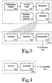
- FIG. 3 illustrates a block diagram of one embodiment of a remote transmitter 300 in communication with the corresponding trigger circuit 220a.
- the remote transmitter 300 includes a controller 302, a modulator 304, an antenna 306, a stimulation switch 308, and a stimulus intensity selector 310, which is typically a switch or other adjustment mechanism.
- the controller 302 is responsive to the activation of the stimulation switch 308 and reads the current value of the stimulus intensity selector 310.
- the stimulus intensity value is coded into a signal that is modulated by modulator 304 and transmitted by antenna 306.
- the trigger circuit 220a includes an antenna 312, a receiver circuit 314 attuned to the transmitter frequency, and a demodulator 316.
- the coded signal received by the receiver circuit 314 is demodulated by demodulator 316 and passed to the controller 204.
- the controller 204 reads the stimulus intensity value and adjusts the power converter drive signal to provide the desired output voltage.
- the controller 204 sends the correction pulse control signal to the correction pulse switch 210 and creates the potential across the primary of the transformer 216.
- the potential across the primary of the transformer 216 determines the intensity of the correction stimulus.
- the controller 204 cause the desired stimulus intensity selected at the remote transmitter 300 to be applied to the animal 108.
- FIG. 3 While the block diagram of Figure 3 has been described in terms of an RF transmitter/receiver pair, other embodiments are contemplated. Exemplary functions performed using wireless communications include establishing a boundary, initiating the application of a stimulus, and modifying settings of the stimulation unit. Commonly used wireless communication technologies include RF communications, infrared and other optical communication, and magnetic/electromagnetic field communication. One skilled in the art will recognize that wireless communication technologies evolve and would not consider the current invention limited to the wireless communication technologies or the exemplary uses disclosed herein.
- FIG. 4 illustrates a block diagram of another embodiment of a local trigger circuit 220b.
- the local trigger circuit 220b generates a stimulus request locally.
- the local trigger circuit 220b includes a controller 400 in communication with a sensor 402 that monitors a condition of or in the vicinity of the animal wearing the stimulus unit.
- the sensor 402 is a bark detection circuit including a microphone and/ or a vibration sensor.
- the controller 400 evaluates the monitored condition reported by the sensor 402 and determines whether a stimulus request is warranted.
- the controller 400 further evaluates the monitored condition in view of additional criteria (e.g., historical barking patterns and/or length of current bark episode) and adjusts the stimulus intensity automatically.
- the stimulus intensity can be manually selected by adding a stimulus intensity selector as described with respect to Figure 3 . Further embodiments allow the manual selection of the base stimulus intensity with automatic adjustment of the stimulus intensity by controller in response to monitored conditions.
- the controller 400 can be implemented as an additional function in the controller 204 previously described in some embodiments.
- commonly used monitoring technologies include sound wave detection, vibration detection, and environmental or physiological condition detection.
- FIG. 5 is a schematic diagram of one embodiment of the variable voltage electronic pet training apparatus 100.
- the power source 200 is represented by battery B1.
- Battery B1 directly feeds the voltage regulator 202, which includes regulator U1 and capacitors C5 and C6 in the illustrated embodiment.
- the regulated voltage provides a stable regulated voltage for the controller 204, which in the illustrated embodiment is a microcontroller.
- the microcontroller interfaces to all devices through its input/ output port pins under the control of the embedded application firmware.
- the microcontroller has both digital and analog circuitry including analog comparators and a pulse-width modulation output.
- One output of the controller is the power converter drive signal that drives the gate of transistor Q1 biased by resistors R1A and R1B.
- the power converter drive signal is a pulse-width modulated signal that controls corresponds to the desired output voltage.
- Transistor Q1 controls the power converter 206, which includes inductor L1, capacitor C1, inductor L2, and breakdown diode D1 in the illustrated embodiment.
- the illustrated power converter 206 is a single-ended primary inductance converter (SEPIC). SEPIC topologies are useful because the output voltage can be higher or lower than the battery voltage and are well-suited for use with lithium batteries. However, one skilled in the art will recognize that other power converter circuits can be used without departing from the scope and spirit of the present invention.
- the output of the power converter 206 at breakdown diode D1 charges the energy storage capacitor C2.
- the voltage variation to C2 determines the correction energy provided.
- the controller 204 sends a signal to the gate of the correction pulse switch transistor Q2, which is biased by resistors R2A and R2B.
- the activation signal applied to the gate of the correction pulse switch transistor Q2 is a fixed output that does not vary in duration, frequency, or amplitude.
- the voltage applied to the primary of the transformer 216 is the difference between the voltage across the breakdown diode D1 and the voltage at the node connected by the correction pulse switch 210. In the illustrated embodiment, the node is connected to ground.
- the stimulus intensity is related directly to the output voltage of the power converter 206 when the correction pulse switch 210 is activated.
- the high-voltage transformer 216 steps up the voltage across the primary winding and transfers the secondary winding voltage to the animal through electrodes 218 to produce a correction stimulus.
- the activation signal is a constant voltage.
- the activation signal is a pulse train but not a variable pulse train.
- a pulse train is a series of pulses used to control the correction pulse switch. Typical pulse train sequences include one OFF-ON-OFF pulse or a series of OFF-ON-OFF transitions with predetermined OFF and ON periods. The ON and OFF periods do not have to be equal and the number of pulse trains can be one or several.
- the activation signal i.e., the pulse trains
- Stimulus intensity remains a function of the voltage applied to the transformer using the voltage variation techniques described herein.
- Another embodiment has predetermined activation signals for each intensity level to attempt to optimize the energy transfer efficiency, i.e., to better match the power converter and energy storage circuitry with the transformer.
- the stimulus intensity remains tied to the voltage applied to the transformer using the voltage variation techniques described herein. Only the efficiency of the energy transfer is adjusted by having customized activation signals for each correction level. For example, if the correction pulse control signal is set to three pulse trains of eight pulses with a fixed ON-OFF periods for the highest intensity, a lower intensity setting with a lower voltage applied to the transformer might have two pulse trains of eight pulses to improve the energy transfer efficiency at the lower voltage.
- battery life is improved, i.e., power is not wasted through inefficient activation of the correction pulse switch.
- the varying signal that switches the correction pulse switch transistor Q2 on and off to control the amount of charge applied to the transformer through a combination of the variable voltage output of the power converter 206 and the frequency or duration of the activation signal applied to the correction pulse switch 210.
- the efficiency of the correction stimulus is changed.
- the transformer is a pulse transformer and the activation signal is varied in both the number of pulses in the signal and the pulse width. Generally, a greater number of pulses and wider pulse widths keep the correction pulse switch 210 active longer resulting in a more intense correction stimulus because more energy is applied to the primary winding of the pulse transformer.
- the power converter 206 is located on the high side of the transformer 216 and low side of the transformer 216 is connected to ground through the correction pulse switch 210.
- This arrangement allows the output voltage of the power converter to increase the potential across the primary of the transformer up to the battery voltage (or beyond using SEPIC topologies).
- SEPIC topologies One skilled in the art will appreciate other implementations that allow the potential across the primary of the transformer to be controlled.
- the high side of the transformer is connected to a node where the battery voltage through the correction pulse switch and the low side of the transformer is connected to the power converter.
- This arrangement allows the output voltage of the power converter to reduce the potential across the primary of the transformer by raising the voltage on the low side of the transformer and reducing the potential across the primary of the transformer.
- a first power converter is connected to the high side of the transformer and a second power converter to the low side of the transformer. By adjusting either or both of the first and second power converters, the potential across the primary of the transformer is varied.
- the output of the power converter 206 before breakdown diode D1 charges the peak hold detector 208, which includes capacitor C3, the voltage divider made up of resistors R3 and R4, and a noise filter capacitor C4.
- the voltage divider connects to the comparator input of the microcontroller to provide feedback allowing microcontroller to adjust and regulate the power converter 206 and maintain a desired voltage.
- the energy recovery circuit 212 includes transistors Q10A and Q10B and biasing resistors R10A, R10B, R10C, R10D, and R10E.
- the energy recovery circuit 212 provides the ability to recover unspent energy from the energy storage capacitor C2, which extends battery life.
- the setting of the output voltage is controlled by the operation of the transmitter.
- One of several levels can be selected by the user.
- the correction button is pressed, the value of the correction level is sent to the receiver, which decodes and verifies the proper signal and data format.
- the controller translates the correction level selected to a predetermined equivalent voltage.
- the desired voltage is generated by the voltage converter and presented to the correction capacitor.
- the correction pulse switch is turned on to deliver the correction.
- Figure 5 represents one specific implementation of the general circuit described in the block diagram of Figure 2 .
- One skilled in the art will appreciate the differing implementations that can be achieved through the substitution of parts and subcircuits without departing from the scope of the present invention as defined by the appended claims.
- the differing implementations reflect design choices by one skilled in the art.
Landscapes
- Life Sciences & Earth Sciences (AREA)
- Environmental Sciences (AREA)
- Animal Husbandry (AREA)
- Biodiversity & Conservation Biology (AREA)
- Health & Medical Sciences (AREA)
- General Health & Medical Sciences (AREA)
- Physical Education & Sports Medicine (AREA)
- Animal Behavior & Ethology (AREA)
- Zoology (AREA)
- Electrotherapy Devices (AREA)
- Pharmaceuticals Containing Other Organic And Inorganic Compounds (AREA)
Claims (12)
- Elektronische Haustiertrainiervorrichtung mit variabler Spannung, umfassend:eine Auslöseschaltung (220), die eine Reizanforderung erzeugt;eine Steuerungseinrichtung (204) in Verbindung mit der Auslöseschaltung (220), wobei die Steuerungseinrichtung (204) als Reaktion auf den Empfang der Reizanforderung ein Korrekturimpulsschalter-Aktivierungssignal erzeugt, wobei die Steuerungseinrichtung (204) ein Leistungswandler-Antriebssignal erzeugt, das einer gewünschten Reizintensität entspricht;einen Leistungswandler (206), der einen Eingang in Verbindung mit der Steuerungseinrichtung (204) aufweist, wobei der Leistungswandler (206) eine Ausgangsspannung erzeugt, die dem Leistungswandler-Antriebssignal an einem Ausgang entspricht;einen Transformator (216), der eine Primärseite und eine Sekundärseite aufweist, wobei die Primärseite in Verbindung mit dem Ausgang des Leistungswandlers steht;einen Korrekturimpulsschalter (210) in Verbindung mit der Steuerungseinrichtung (204), wobei der Korrekturimpulsschalter (210) in Verbindung mit der Primärseite steht, wobei der Korrekturimpulsschalter (210) die Primärseite mit einem Knoten verbindet, der eine Spannung aufweist und ein Potential über die Primärseite erzeugt, das gleich einem Unterschied zwischen der Ausgangsspannung des Leistungswandlers und der Knotenspannung ist; undein Paar von Elektroden, wobei jede des Paares von Elektroden mit der Sekundärseite verbunden ist, wobei das Paar von Elektroden zum Übertragen eines Korrekturreizes an ein Tier bestimmt ist, wobei der Korrekturreiz eine von dem Potential über die Primärseite gestufte Spannung aufweist, undeine Energiespeicherschaltung in Verbindung mit dem Leistungswandler und dem Transformator,dadurch gekennzeichnet, dassdie elektronische Haustiertrainiervorrichtung mit variabler Spannung ferner eine Energierückgewinnungsschaltung in Verbindung mit der Energiespeicherschaltung und der Steuerungseinrichtung umfasst.
- Elektronische Haustiertrainiervorrichtung mit variabler Spannung nach Anspruch 1, wobei der Transformator in geschalteter Verbindung mit dem Leistungswandler steht.
- Elektronische Haustiertrainiervorrichtung mit variabler Spannung nach Anspruch 2, wobei der Korrekturimpulsschalter zwischen dem Ausgang des Leistungswandlers und der Primärseite angeordnet ist.
- Elektronische Haustiertrainiervorrichtung mit variabler Spannung nach Anspruch 1, ferner umfassend einen zweiten Leistungswandler in Verbindung mit der Steuerungseinrichtung und dem Knoten, wobei der zweite Leistungswandler als Reaktion auf ein zweites Leistungswandler-Antriebssignal, das durch die Steuerungseinrichtung erzeugt wird, eine Ausgangsspannung erzeugt, wobei es sich bei der Ausgangsspannung des zweiten Leistungswandlers um die Knotenspannung handelt.
- Elektronische Haustiertrainiervorrichtung mit variabler Spannung nach Anspruch 1, ferner umfassend einen Spitzenwerthaltedetektor in Verbindung mit dem Leistungswandler und der Steuerungseinrichtung, wobei der Spitzenwerthaltedetektor eine Rückkopplung der Ausgangsspannung des Leistungswandlers bereitstellt, die es der Steuerungseinrichtung ermöglicht, das Leistungswandler-Antriebssignal derart einzustellen, dass eine gewünschte Ausgangsspannung des Leistungswandlers aufrechterhalten wird.
- Elektronische Haustiertrainiervorrichtung mit variabler Spannung nach Anspruch 1, wobei die Energierückgewinnungsschaltung Transistoren (Q10A, Q10B) und Vorspannungswiderstände (R10A, R10B, R10C, R10D, R10E) umfasst, die die Fähigkeit bereitstellen, unverbrauchte Energie von einem Energiespeicherkondensator (C2) rückzugewinnen.
- Elektronische Haustiertrainiervorrichtung mit variabler Spannung nach Anspruch 1, wobei das Korrekturimpulsschalter-Aktivierungssignal für jede gewünschte Reizintensität identisch ist.
- Elektronische Haustiertrainiervorrichtung mit variabler Spannung nach Anspruch 1, wobei das Korrekturimpulsschalter-Aktivierungssignal basierend auf der gewünschten Reizintensität verändert wird, um den Wirkungsgrad der Energieübertragung zwischen dem Leistungswandler und dem Transformator zu verbessern.
- Elektronische Haustiertrainiervorrichtung mit variabler Spannung nach Anspruch 1, wobei die Reizanforderung die gewünschte Reizintensität an die Steuerungseinrichtung kommuniziert.
- Elektronische Haustiertrainiervorrichtung mit variabler Spannung nach Anspruch 1, ferner umfassend eine Reizintensitäts-Auswahleinrichtung, wobei die Steuerungseinrichtung die gewünschte Reizintensität von der Reizintensitäts-Auswahleinrichtung abliest.
- Elektronische Haustiertrainiervorrichtung mit variabler Spannung nach Anspruch 1, wobei die Steuerungseinrichtung die Reizintensität als Reaktion auf das Verhalten des Tieres automatisch verändert.
- Elektronische Haustiertrainiervorrichtung mit variabler Spannung nach Anspruch 1, wobei der Leistungswandler ein Single-Ended-Primärinduktivitätswandler ist.
Applications Claiming Priority (2)
| Application Number | Priority Date | Filing Date | Title |
|---|---|---|---|
| US11/386,414 US8011327B2 (en) | 2006-03-22 | 2006-03-22 | Variable voltage electronic pet training apparatus |
| PCT/US2006/011734 WO2007108812A1 (en) | 2006-03-22 | 2006-03-31 | Variable voltage electronic pet training apparatus |
Publications (3)
| Publication Number | Publication Date |
|---|---|
| EP1996012A1 EP1996012A1 (de) | 2008-12-03 |
| EP1996012A4 EP1996012A4 (de) | 2016-10-19 |
| EP1996012B1 true EP1996012B1 (de) | 2021-08-25 |
Family
ID=38522754
Family Applications (1)
| Application Number | Title | Priority Date | Filing Date |
|---|---|---|---|
| EP06740089.5A Active EP1996012B1 (de) | 2006-03-22 | 2006-03-31 | Elektronische haustiertrainiervorrichtung mit variabler spannung |
Country Status (4)
| Country | Link |
|---|---|
| US (1) | US8011327B2 (de) |
| EP (1) | EP1996012B1 (de) |
| ES (1) | ES2349862T3 (de) |
| WO (1) | WO2007108812A1 (de) |
Families Citing this family (74)
| Publication number | Priority date | Publication date | Assignee | Title |
|---|---|---|---|---|
| US6910911B2 (en) | 2002-06-27 | 2005-06-28 | Vocollect, Inc. | Break-away electrical connector |
| US20060253281A1 (en) * | 2004-11-24 | 2006-11-09 | Alan Letzt | Healthcare communications and documentation system |
| US20090111598A1 (en) * | 2007-10-31 | 2009-04-30 | O'brien Scott | Systems and methods for improving golf swing |
| USD583827S1 (en) * | 2008-02-20 | 2008-12-30 | Vocollect Healthcare Systems, Inc. | Mobile electronics training device |
| USD626949S1 (en) | 2008-02-20 | 2010-11-09 | Vocollect Healthcare Systems, Inc. | Body-worn mobile device |
| US8255225B2 (en) * | 2008-08-07 | 2012-08-28 | Vocollect Healthcare Systems, Inc. | Voice assistant system |
| US8451101B2 (en) * | 2008-08-28 | 2013-05-28 | Vocollect, Inc. | Speech-driven patient care system with wearable devices |
| US8386261B2 (en) * | 2008-11-14 | 2013-02-26 | Vocollect Healthcare Systems, Inc. | Training/coaching system for a voice-enabled work environment |
| US20100156643A1 (en) * | 2008-12-15 | 2010-06-24 | Greg Gillis | Stimulus Delivery Device Having an Adjustable Stimulus Intensity Range |
| US20110029315A1 (en) * | 2009-07-28 | 2011-02-03 | Brent Nichols | Voice directed system and method for messaging to multiple recipients |
| US20110221597A1 (en) * | 2010-03-11 | 2011-09-15 | Jameson James L | Animal Training Device Having a Programmable Stimulus Delivery Switch |
| US8659397B2 (en) | 2010-07-22 | 2014-02-25 | Vocollect, Inc. | Method and system for correctly identifying specific RFID tags |
| USD643400S1 (en) | 2010-08-19 | 2011-08-16 | Vocollect Healthcare Systems, Inc. | Body-worn mobile device |
| USD643013S1 (en) | 2010-08-20 | 2011-08-09 | Vocollect Healthcare Systems, Inc. | Body-worn mobile device |
| US8887670B2 (en) | 2010-12-22 | 2014-11-18 | E-Collar Technologies, Inc. | Remote animal training system using voltage-to-frequency conversion |
| US8757098B2 (en) | 2010-12-22 | 2014-06-24 | E-Collar Technologies, Inc. | Remote animal training system using voltage-to-frequency conversion |
| US8881686B2 (en) * | 2010-12-22 | 2014-11-11 | E-Collar Technologies, Inc. | Remote animal training system using voltage-to-frequency conversion |
| US8833309B2 (en) | 2010-12-22 | 2014-09-16 | E-Collar Technologies, Inc. | Remote animal training system using voltage-to-frequency conversion |
| US10154651B2 (en) | 2011-12-05 | 2018-12-18 | Radio Systems Corporation | Integrated dog tracking and stimulus delivery system |
| US11470814B2 (en) | 2011-12-05 | 2022-10-18 | Radio Systems Corporation | Piezoelectric detection coupling of a bark collar |
| US11553692B2 (en) | 2011-12-05 | 2023-01-17 | Radio Systems Corporation | Piezoelectric detection coupling of a bark collar |
| US10674709B2 (en) | 2011-12-05 | 2020-06-09 | Radio Systems Corporation | Piezoelectric detection coupling of a bark collar |
| US8783212B2 (en) * | 2012-03-09 | 2014-07-22 | Bart Bellon | Animal collar with integrated electronics |
| US10228447B2 (en) | 2013-03-15 | 2019-03-12 | Radio Systems Corporation | Integrated apparatus and method to combine a wireless fence collar with GPS tracking capability |
| USD734900S1 (en) * | 2013-12-31 | 2015-07-21 | i4c Innovations Inc. | Electronic dog collar |
| USD748350S1 (en) * | 2013-12-31 | 2016-01-26 | i4c Innovations Inc. | Electronic dog collar |
| USD747566S1 (en) | 2013-12-31 | 2016-01-12 | i4c Innovations Inc. | Electronic dog collar |
| USD745229S1 (en) | 2013-12-31 | 2015-12-08 | i4c Innovations Inc. | Electronic module for a dog collar |
| USD737004S1 (en) | 2014-01-13 | 2015-08-18 | Radio Systems Corporation | Handheld transmitter |
| USD759908S1 (en) | 2014-01-13 | 2016-06-21 | Radio Systems Corporation | Handheld transmitter |
| USD736486S1 (en) | 2014-01-13 | 2015-08-11 | Radio Systems Corporation | Handheld transceiver with display |
| US9326486B2 (en) | 2014-04-29 | 2016-05-03 | Motorola Solutions, Inc. | Method and apparatus for blocking unwanted canine interactions |
| US9439396B2 (en) | 2014-04-29 | 2016-09-13 | Motorola Solutions, Inc. | Method and apparatus for blocking unwanted canine interactions |
| US9883656B1 (en) * | 2014-07-10 | 2018-02-06 | Phillip Turner | House breaking training harness for a canine using body position measurements |
| US10231440B2 (en) | 2015-06-16 | 2019-03-19 | Radio Systems Corporation | RF beacon proximity determination enhancement |
| US10045512B2 (en) | 2015-06-16 | 2018-08-14 | Radio Systems Corporation | Systems and methods for monitoring a subject in a premise |
| US10645908B2 (en) | 2015-06-16 | 2020-05-12 | Radio Systems Corporation | Systems and methods for providing a sound masking environment |
| US10387587B2 (en) | 2015-08-06 | 2019-08-20 | Radio Systems Corporation | Computer simulation of animal training scenarios and environments |
| US10521523B2 (en) | 2015-08-06 | 2019-12-31 | Radio Systems Corporation | Computer simulation of animal training scenarios and environments |
| USD788999S1 (en) | 2016-03-11 | 2017-06-06 | Radio Systems Corporation | Receiver for a pet collar |
| USD880082S1 (en) | 2016-03-11 | 2020-03-31 | Radio Systems Corporation | Receiver for a pet collar |
| USD798003S1 (en) * | 2016-06-17 | 2017-09-19 | Shenzhen YueHuanYu Ribbon Co., Ltd. | Stop barking device with remote control |
| US10268220B2 (en) | 2016-07-14 | 2019-04-23 | Radio Systems Corporation | Apparatus, systems and methods for generating voltage excitation waveforms |
| USD836858S1 (en) * | 2017-01-27 | 2018-12-25 | Radio Systems Corporation | Transmitter for a pet trainer |
| WO2018157111A1 (en) | 2017-02-27 | 2018-08-30 | Radio Systems Corporation | Threshold barrier system |
| USD815372S1 (en) | 2017-03-03 | 2018-04-10 | Radio Systems Corporation | Handheld transmitter for a pet trainer |
| US11197461B2 (en) | 2017-04-21 | 2021-12-14 | Radio Systems Corporation | Pet spray training system |
| US11185052B2 (en) | 2017-04-21 | 2021-11-30 | Radio Systems Corporation | Pet spray training system |
| USD828965S1 (en) * | 2017-05-17 | 2018-09-18 | Jian Wen | Bark control |
| US10375930B1 (en) * | 2017-07-07 | 2019-08-13 | Chad R. James | Animal training device that controls stimulus using proportional pressure-based input |
| US11394196B2 (en) | 2017-11-10 | 2022-07-19 | Radio Systems Corporation | Interactive application to protect pet containment systems from external surge damage |
| USD853666S1 (en) * | 2017-11-21 | 2019-07-09 | Shenzhen Dogcare Innovation & Technology Co., Ltd. | Bark control unit |
| US10842128B2 (en) | 2017-12-12 | 2020-11-24 | Radio Systems Corporation | Method and apparatus for applying, monitoring, and adjusting a stimulus to a pet |
| AU2018383758B2 (en) * | 2017-12-12 | 2024-05-02 | Radio Systems Corporation | Method and apparatus for applying, monitoring, and adjusting a stimulus to a pet |
| US10986813B2 (en) | 2017-12-12 | 2021-04-27 | Radio Systems Corporation | Method and apparatus for applying, monitoring, and adjusting a stimulus to a pet |
| US11372077B2 (en) | 2017-12-15 | 2022-06-28 | Radio Systems Corporation | Location based wireless pet containment system using single base unit |
| US10514439B2 (en) | 2017-12-15 | 2019-12-24 | Radio Systems Corporation | Location based wireless pet containment system using single base unit |
| USD850732S1 (en) * | 2018-02-11 | 2019-06-04 | Fuliang Dong | Stop barking device |
| USD850733S1 (en) * | 2018-02-11 | 2019-06-04 | Fuliang Dong | Stop barking device |
| WO2019178222A1 (en) | 2018-03-14 | 2019-09-19 | Protect Animals with Satellites, LLC | Corrective collar utilizing geolocation technology |
| USD888353S1 (en) * | 2019-01-25 | 2020-06-23 | Shenzhen Xcho Technology Limited | Bark control |
| USD898307S1 (en) * | 2019-05-28 | 2020-10-06 | Xiaoni Yang | Remote controlled dog training device |
| USD898309S1 (en) * | 2019-05-28 | 2020-10-06 | Xiaoni Yang | Remote controlled dog training device |
| USD898308S1 (en) * | 2019-05-28 | 2020-10-06 | Shenzhen Tianzhe Science And Technology Co., Limited | Remote controlled dog training device |
| US11238889B2 (en) | 2019-07-25 | 2022-02-01 | Radio Systems Corporation | Systems and methods for remote multi-directional bark deterrence |
| USD929051S1 (en) * | 2019-10-01 | 2021-08-24 | Shenzhen Patpet Technology CO., LTD | Receiver of dog training collar |
| USD929682S1 (en) * | 2020-01-07 | 2021-08-31 | Shenzhen Patpet Technology CO., LTD | No bark collar device |
| US11490597B2 (en) | 2020-07-04 | 2022-11-08 | Radio Systems Corporation | Systems, methods, and apparatus for establishing keep out zones within wireless containment regions |
| US12219933B1 (en) | 2020-09-24 | 2025-02-11 | Protect Animals with Satellites, LLC | System and method for tracking an animal and for preventing the animal from attacking another animal |
| USD925143S1 (en) * | 2020-10-20 | 2021-07-13 | Shenzhen Smart Pet Technology Co., Ltd | Stop barking device |
| USD925141S1 (en) * | 2021-01-12 | 2021-07-13 | Shenzhen Xinchi Network & Tech Co., Ltd. | Bark collar device for dog |
| CA3207062A1 (en) | 2021-03-08 | 2022-09-15 | Kenneth Scott EHRMAN | Corrective collar utilizing geolocation technology |
| US20220394955A1 (en) * | 2021-06-09 | 2022-12-15 | E-Collar Technologies, Inc. | Remote animal training system |
| CN119183980A (zh) * | 2024-09-25 | 2024-12-27 | 广州易海帮科技有限公司 | 宠物智能生态系统 |
Family Cites Families (12)
| Publication number | Priority date | Publication date | Assignee | Title |
|---|---|---|---|---|
| US4802482A (en) | 1987-09-21 | 1989-02-07 | Tri-Tronics, Inc. | Method and apparatus for remote control of animal training stimulus |
| US5054428A (en) | 1989-06-29 | 1991-10-08 | Tri-Tronics, Inc. | Method and apparatus for remote conditioned cue control of animal training stimulus |
| US5666908A (en) | 1995-07-05 | 1997-09-16 | So; Ho Yun | Animal training device |
| US6079367A (en) | 1997-10-10 | 2000-06-27 | Dogwatch, Inc. | Animal training apparatus and method |
| US6166643A (en) | 1997-10-23 | 2000-12-26 | Janning; Joseph J. | Method and apparatus for controlling the whereabouts of an animal |
| US6327999B1 (en) | 1999-12-10 | 2001-12-11 | Innotek, Inc. | Electroshock stimulus monitoring method and apparatus |
| KR100400096B1 (ko) * | 2000-09-19 | 2003-10-01 | 소호연 | 수신 안테나가 내장된 동물훈련장치 및 그 제어방법 |
| KR100417198B1 (ko) | 2001-12-21 | 2004-02-05 | 김준수 | 동물 짖음방지/훈련 장치 |
| US7017524B2 (en) * | 2003-12-31 | 2006-03-28 | Radio Systems Corporation | Intensity variation device for training animals |
| US6928958B2 (en) | 2004-01-07 | 2005-08-16 | Tri-Tronics, Inc. | Vibration sensor assembly and method for bark controller |
| KR100718841B1 (ko) | 2004-10-30 | 2007-05-16 | 김준수 | 동물 귀환 유도 장치 |
| US7180759B2 (en) * | 2004-11-03 | 2007-02-20 | Square D Company | Push-pull inverter with snubber energy recovery |
-
2001
- 2001-11-30 ES ES01996012T patent/ES2349862T3/es not_active Expired - Lifetime
-
2006
- 2006-03-22 US US11/386,414 patent/US8011327B2/en active Active
- 2006-03-31 EP EP06740089.5A patent/EP1996012B1/de active Active
- 2006-03-31 WO PCT/US2006/011734 patent/WO2007108812A1/en not_active Ceased
Non-Patent Citations (1)
| Title |
|---|
| None * |
Also Published As
| Publication number | Publication date |
|---|---|
| US8011327B2 (en) | 2011-09-06 |
| ES2349862T3 (es) | 2011-01-12 |
| US20070221138A1 (en) | 2007-09-27 |
| WO2007108812A1 (en) | 2007-09-27 |
| EP1996012A4 (de) | 2016-10-19 |
| EP1996012A1 (de) | 2008-12-03 |
Similar Documents
| Publication | Publication Date | Title |
|---|---|---|
| EP1996012B1 (de) | Elektronische haustiertrainiervorrichtung mit variabler spannung | |
| US7819087B2 (en) | Remote controlled animal training system with wireless communication system | |
| US4802482A (en) | Method and apparatus for remote control of animal training stimulus | |
| US8020522B2 (en) | Circuit and method for checking the impedance of electrodes and for controlling the intensity of an electric stimulus | |
| US20130112153A1 (en) | Remote animal training system using voltage-to-frequency conversion | |
| US6549133B2 (en) | Remote transmitter and method | |
| US8833309B2 (en) | Remote animal training system using voltage-to-frequency conversion | |
| US20030040291A1 (en) | Transmitter system for wireless communication with implanted devices | |
| US20120160182A1 (en) | Remote animal training system using voltage-to-frequency conversion | |
| US5054428A (en) | Method and apparatus for remote conditioned cue control of animal training stimulus | |
| US7379775B2 (en) | Voltage converter for implantable microstimulator using RF-powering coil | |
| US7081821B2 (en) | Electronic fence system and controlling method thereof | |
| CN101084739A (zh) | 具有最少开关的动物限制系统发射器设置的控制 | |
| DE69730529T2 (de) | Schaltkreis und verfahren zur leistungsregelung die bei einem mobiltelefon benutzt wird | |
| US6474269B2 (en) | Animal training apparatus having a receiving antenna and method of controlling the apparatus | |
| US6184790B1 (en) | Animal shock collar with low impedance transformer | |
| US8260431B2 (en) | Multi-mode pet training device | |
| KR19990070416A (ko) | 동물훈련장치 및 그 제어방법 | |
| US20030116101A1 (en) | Pet training device | |
| AU7600794A (en) | Multi-channel animal control device with external data communication | |
| US20090013939A1 (en) | Apparatus and method for restricting movement of an animal into or out of a defined area | |
| US20010004238A1 (en) | Animal shock collar with low impedance transformer | |
| JP2016533152A (ja) | マイクロプロセッサ制御されたeクラスドライバ | |
| US5697076A (en) | Suspended carrier modulation of high-Q transmitters | |
| US7937042B2 (en) | Animal training and tracking system using RF identification tags |
Legal Events
| Date | Code | Title | Description |
|---|---|---|---|
| PUAI | Public reference made under article 153(3) epc to a published international application that has entered the european phase |
Free format text: ORIGINAL CODE: 0009012 |
|
| 17P | Request for examination filed |
Effective date: 20080919 |
|
| AK | Designated contracting states |
Kind code of ref document: A1 Designated state(s): BE FR GB |
|
| RBV | Designated contracting states (corrected) |
Designated state(s): BE FR GB |
|
| RAP1 | Party data changed (applicant data changed or rights of an application transferred) |
Owner name: RADIO SYSTEMS CORPORATION |
|
| DAX | Request for extension of the european patent (deleted) | ||
| RA4 | Supplementary search report drawn up and despatched (corrected) |
Effective date: 20160915 |
|
| RIC1 | Information provided on ipc code assigned before grant |
Ipc: A01K 15/02 20060101ALI20160909BHEP Ipc: A01K 27/00 20060101AFI20160909BHEP |
|
| STAA | Information on the status of an ep patent application or granted ep patent |
Free format text: STATUS: EXAMINATION IS IN PROGRESS |
|
| 17Q | First examination report despatched |
Effective date: 20170616 |
|
| GRAP | Despatch of communication of intention to grant a patent |
Free format text: ORIGINAL CODE: EPIDOSNIGR1 |
|
| STAA | Information on the status of an ep patent application or granted ep patent |
Free format text: STATUS: GRANT OF PATENT IS INTENDED |
|
| INTG | Intention to grant announced |
Effective date: 20210326 |
|
| GRAS | Grant fee paid |
Free format text: ORIGINAL CODE: EPIDOSNIGR3 |
|
| GRAA | (expected) grant |
Free format text: ORIGINAL CODE: 0009210 |
|
| STAA | Information on the status of an ep patent application or granted ep patent |
Free format text: STATUS: THE PATENT HAS BEEN GRANTED |
|
| AK | Designated contracting states |
Kind code of ref document: B1 Designated state(s): BE FR GB |
|
| REG | Reference to a national code |
Ref country code: GB Ref legal event code: FG4D |
|
| PLBE | No opposition filed within time limit |
Free format text: ORIGINAL CODE: 0009261 |
|
| STAA | Information on the status of an ep patent application or granted ep patent |
Free format text: STATUS: NO OPPOSITION FILED WITHIN TIME LIMIT |
|
| 26N | No opposition filed |
Effective date: 20220527 |
|
| REG | Reference to a national code |
Ref country code: BE Ref legal event code: MM Effective date: 20220331 |
|
| PG25 | Lapsed in a contracting state [announced via postgrant information from national office to epo] |
Ref country code: BE Free format text: LAPSE BECAUSE OF NON-PAYMENT OF DUE FEES Effective date: 20220331 |
|
| PGFP | Annual fee paid to national office [announced via postgrant information from national office to epo] |
Ref country code: FR Payment date: 20250210 Year of fee payment: 20 |
|
| PGFP | Annual fee paid to national office [announced via postgrant information from national office to epo] |
Ref country code: GB Payment date: 20250206 Year of fee payment: 20 |