EP1995815B1 - Verre organique électrolytique, son procédé de fabrication et dispositif le comprenant - Google Patents
Verre organique électrolytique, son procédé de fabrication et dispositif le comprenant Download PDFInfo
- Publication number
- EP1995815B1 EP1995815B1 EP08290475A EP08290475A EP1995815B1 EP 1995815 B1 EP1995815 B1 EP 1995815B1 EP 08290475 A EP08290475 A EP 08290475A EP 08290475 A EP08290475 A EP 08290475A EP 1995815 B1 EP1995815 B1 EP 1995815B1
- Authority
- EP
- European Patent Office
- Prior art keywords
- lithium
- electrolyte
- electrolyte according
- solid
- solid electrolyte
- Prior art date
- Legal status (The legal status is an assumption and is not a legal conclusion. Google has not performed a legal analysis and makes no representation as to the accuracy of the status listed.)
- Active
Links
Images

Classifications
-
- H—ELECTRICITY
- H01—ELECTRIC ELEMENTS
- H01M—PROCESSES OR MEANS, e.g. BATTERIES, FOR THE DIRECT CONVERSION OF CHEMICAL ENERGY INTO ELECTRICAL ENERGY
- H01M10/00—Secondary cells; Manufacture thereof
- H01M10/05—Accumulators with non-aqueous electrolyte
- H01M10/056—Accumulators with non-aqueous electrolyte characterised by the materials used as electrolytes, e.g. mixed inorganic/organic electrolytes
-
- C—CHEMISTRY; METALLURGY
- C23—COATING METALLIC MATERIAL; COATING MATERIAL WITH METALLIC MATERIAL; CHEMICAL SURFACE TREATMENT; DIFFUSION TREATMENT OF METALLIC MATERIAL; COATING BY VACUUM EVAPORATION, BY SPUTTERING, BY ION IMPLANTATION OR BY CHEMICAL VAPOUR DEPOSITION, IN GENERAL; INHIBITING CORROSION OF METALLIC MATERIAL OR INCRUSTATION IN GENERAL
- C23C—COATING METALLIC MATERIAL; COATING MATERIAL WITH METALLIC MATERIAL; SURFACE TREATMENT OF METALLIC MATERIAL BY DIFFUSION INTO THE SURFACE, BY CHEMICAL CONVERSION OR SUBSTITUTION; COATING BY VACUUM EVAPORATION, BY SPUTTERING, BY ION IMPLANTATION OR BY CHEMICAL VAPOUR DEPOSITION, IN GENERAL
- C23C16/00—Chemical coating by decomposition of gaseous compounds, without leaving reaction products of surface material in the coating, i.e. chemical vapour deposition [CVD] processes
- C23C16/22—Chemical coating by decomposition of gaseous compounds, without leaving reaction products of surface material in the coating, i.e. chemical vapour deposition [CVD] processes characterised by the deposition of inorganic material, other than metallic material
- C23C16/30—Deposition of compounds, mixtures or solid solutions, e.g. borides, carbides, nitrides
-
- H—ELECTRICITY
- H01—ELECTRIC ELEMENTS
- H01M—PROCESSES OR MEANS, e.g. BATTERIES, FOR THE DIRECT CONVERSION OF CHEMICAL ENERGY INTO ELECTRICAL ENERGY
- H01M10/00—Secondary cells; Manufacture thereof
- H01M10/05—Accumulators with non-aqueous electrolyte
- H01M10/052—Li-accumulators
-
- H—ELECTRICITY
- H01—ELECTRIC ELEMENTS
- H01M—PROCESSES OR MEANS, e.g. BATTERIES, FOR THE DIRECT CONVERSION OF CHEMICAL ENERGY INTO ELECTRICAL ENERGY
- H01M10/00—Secondary cells; Manufacture thereof
- H01M10/05—Accumulators with non-aqueous electrolyte
- H01M10/056—Accumulators with non-aqueous electrolyte characterised by the materials used as electrolytes, e.g. mixed inorganic/organic electrolytes
- H01M10/0561—Accumulators with non-aqueous electrolyte characterised by the materials used as electrolytes, e.g. mixed inorganic/organic electrolytes the electrolyte being constituted of inorganic materials only
- H01M10/0562—Solid materials
-
- H—ELECTRICITY
- H01—ELECTRIC ELEMENTS
- H01M—PROCESSES OR MEANS, e.g. BATTERIES, FOR THE DIRECT CONVERSION OF CHEMICAL ENERGY INTO ELECTRICAL ENERGY
- H01M14/00—Electrochemical current or voltage generators not provided for in groups H01M6/00 - H01M12/00; Manufacture thereof
- H01M14/005—Photoelectrochemical storage cells
-
- H—ELECTRICITY
- H01—ELECTRIC ELEMENTS
- H01M—PROCESSES OR MEANS, e.g. BATTERIES, FOR THE DIRECT CONVERSION OF CHEMICAL ENERGY INTO ELECTRICAL ENERGY
- H01M6/00—Primary cells; Manufacture thereof
- H01M6/40—Printed batteries, e.g. thin film batteries
-
- G—PHYSICS
- G02—OPTICS
- G02F—OPTICAL DEVICES OR ARRANGEMENTS FOR THE CONTROL OF LIGHT BY MODIFICATION OF THE OPTICAL PROPERTIES OF THE MEDIA OF THE ELEMENTS INVOLVED THEREIN; NON-LINEAR OPTICS; FREQUENCY-CHANGING OF LIGHT; OPTICAL LOGIC ELEMENTS; OPTICAL ANALOGUE/DIGITAL CONVERTERS
- G02F1/00—Devices or arrangements for the control of the intensity, colour, phase, polarisation or direction of light arriving from an independent light source, e.g. switching, gating or modulating; Non-linear optics
- G02F1/01—Devices or arrangements for the control of the intensity, colour, phase, polarisation or direction of light arriving from an independent light source, e.g. switching, gating or modulating; Non-linear optics for the control of the intensity, phase, polarisation or colour
- G02F1/15—Devices or arrangements for the control of the intensity, colour, phase, polarisation or direction of light arriving from an independent light source, e.g. switching, gating or modulating; Non-linear optics for the control of the intensity, phase, polarisation or colour based on an electrochromic effect
- G02F1/1514—Devices or arrangements for the control of the intensity, colour, phase, polarisation or direction of light arriving from an independent light source, e.g. switching, gating or modulating; Non-linear optics for the control of the intensity, phase, polarisation or colour based on an electrochromic effect characterised by the electrochromic material, e.g. by the electrodeposited material
- G02F1/1523—Devices or arrangements for the control of the intensity, colour, phase, polarisation or direction of light arriving from an independent light source, e.g. switching, gating or modulating; Non-linear optics for the control of the intensity, phase, polarisation or colour based on an electrochromic effect characterised by the electrochromic material, e.g. by the electrodeposited material comprising inorganic material
- G02F1/1525—Devices or arrangements for the control of the intensity, colour, phase, polarisation or direction of light arriving from an independent light source, e.g. switching, gating or modulating; Non-linear optics for the control of the intensity, phase, polarisation or colour based on an electrochromic effect characterised by the electrochromic material, e.g. by the electrodeposited material comprising inorganic material characterised by a particular ion transporting layer, e.g. electrolyte
-
- H—ELECTRICITY
- H01—ELECTRIC ELEMENTS
- H01M—PROCESSES OR MEANS, e.g. BATTERIES, FOR THE DIRECT CONVERSION OF CHEMICAL ENERGY INTO ELECTRICAL ENERGY
- H01M2300/00—Electrolytes
- H01M2300/0017—Non-aqueous electrolytes
- H01M2300/0065—Solid electrolytes
- H01M2300/0068—Solid electrolytes inorganic
-
- Y—GENERAL TAGGING OF NEW TECHNOLOGICAL DEVELOPMENTS; GENERAL TAGGING OF CROSS-SECTIONAL TECHNOLOGIES SPANNING OVER SEVERAL SECTIONS OF THE IPC; TECHNICAL SUBJECTS COVERED BY FORMER USPC CROSS-REFERENCE ART COLLECTIONS [XRACs] AND DIGESTS
- Y02—TECHNOLOGIES OR APPLICATIONS FOR MITIGATION OR ADAPTATION AGAINST CLIMATE CHANGE
- Y02E—REDUCTION OF GREENHOUSE GAS [GHG] EMISSIONS, RELATED TO ENERGY GENERATION, TRANSMISSION OR DISTRIBUTION
- Y02E60/00—Enabling technologies; Technologies with a potential or indirect contribution to GHG emissions mitigation
- Y02E60/10—Energy storage using batteries
-
- Y—GENERAL TAGGING OF NEW TECHNOLOGICAL DEVELOPMENTS; GENERAL TAGGING OF CROSS-SECTIONAL TECHNOLOGIES SPANNING OVER SEVERAL SECTIONS OF THE IPC; TECHNICAL SUBJECTS COVERED BY FORMER USPC CROSS-REFERENCE ART COLLECTIONS [XRACs] AND DIGESTS
- Y02—TECHNOLOGIES OR APPLICATIONS FOR MITIGATION OR ADAPTATION AGAINST CLIMATE CHANGE
- Y02P—CLIMATE CHANGE MITIGATION TECHNOLOGIES IN THE PRODUCTION OR PROCESSING OF GOODS
- Y02P70/00—Climate change mitigation technologies in the production process for final industrial or consumer products
- Y02P70/50—Manufacturing or production processes characterised by the final manufactured product
Definitions
- the invention relates to a solid electrolyte, a process for its manufacture as well as devices comprising it.
- Lithium microbatteries are used in small electronic devices as well as in semiconductor devices.
- the electrolyte is a very influential element on the electrical performance of these microbatteries.
- microbatteries The performance of microbatteries is closely related to the electrical properties of the electrolyte, such as ionic and electronic conductivity.
- microbatteries are used in smart cards, smart tags, power supply of internal clocks and microsystems.
- a lithium salt is directly dissolved in the polymer matrix.
- Ion conductivity is commonly attributed to the mobility of Li + ions within the amorphous matrix of the solid polymer.
- the solid polymer electrolytes have a low glass transition temperature, which generates the formation of crystalline zones capable of trapping Li + ions and inhibiting their mobility.
- the method of elaboration of the polymer electrolytes does not allow the realization of deposits conform to the substrates, that is to say having the same thickness in all points of the substrate.
- glass is meant an amorphous material.
- LiPON Lithium Phosphorus OxyNitride
- LiSON Lithium Sulfur OxyNitride
- LiSiPON Lithium Silicon Phosphorus OxyNitride
- LiPON is the solid electrolyte most used in current microbatteries because it has good electrochemical stability against lithium. However, it has a relatively low ionic conductivity, of the order of 2 x 10 -6 S.cm -1 at room temperature, compared to that of some polymer electrolytes.
- organic glasses such as amorphous carbon ( ⁇ -CxHy) or PDMS-like (SiO x C y H z ) are commonly used in microelectronics. But in this case, they are used as insulators in the interconnection levels and not as an electrolytic organic glass.
- the PCT application WO 2006/059794 A discloses an all-solid lithium ion secondary battery which comprises as an electrolyte an inorganic substance comprising lithium ion conductive crystals.
- LiPON Lithium Phosphorus Oxynitride
- French Patent No. 2,601,017 discloses a composition based on silica derivatives modified with organic groups that can be used as solid electrolyte. These compositions are based on silica and not lithium.
- French Patent No. 2,536,740 discloses an inonically conductive glass for use as a solid lithium electrolyte.
- the invention proposes an electrolytic material, that is to say that allows conduction of lithium ions, depositable in a compliant manner, stable at ambient temperature and having an ionic conductivity greater than 1 x 10 -6 S.cm -1 .
- the solid electrolyte of the invention is distinguished from the polymeric electrolytes of the prior art in that it is not a polymer and therefore does not have a glass transition temperature.
- the electrolyte according to the invention is distinguished from the electrolytes which are glasses of the prior art by its chemical composition: it contains carbon and therefore an organic phase.
- Such amorphous, solid materials of the organic glass type are, a priori, not favorable to obtain good electrolytes insofar as the stability of the organic part vis-à-vis the lithium is generally not good.
- the solid electrolyte of the invention contains more than 12 atomic% of carbon, preferably between 20 and 40 atomic% of carbon, and a hardness greater than or equal to 0.5 GPa, but less than 20 GPa, l
- the amorphous solid electrolyte obtained is both chemically stable with respect to lithium, and has good ionic conduction properties.
- the hardness of the solid electrolyte of the invention was measured by nanoindentation.
- a CSM nanodureness meter is used in continuous multicyl mode, using a Berkovich indentation tip.
- the tip of the indentation tip placed on the surface whose hardness is to be measured, is entrained in the sample by applying a load.
- the charge is then decreased until partial or complete relaxation of the material occurs.
- the load-depth curve is then used to calculate the mechanical properties such as hardness and modulus of elasticity.
- an initial load of 1 mN increased to 10 mN was used until an imprint, left by the application of the load, of 100 to 200 nm. All measurements were performed on 2 ⁇ m thick samples.
- the organic electrolytic glass of the invention contains, in atomic percentage, more than 12% of carbon, preferably between 20 and 40% of carbon, between 1 and 70% of lithium, preferably between 20 and 40% of lithium, between 5 and 50% oxygen, preferably between 15 and 30% oxygen, and between 0 and 40% silicon, preferably between 0 and 15% silicon, and between 10 and 40% hydrogen preferably between 15 and 30% of hydrogen, the sum of the atomic percentages of carbon, lithium, oxygen, silicon and hydrogen being at least 95%.
- the organic electrolytic glass of the invention may comprise only carbon, lithium, oxygen, silicon and hydrogen, it can also be provided to dope by adding materials such as fluorine, boron, phosphorus or nitrogen or their mixtures to give it greater chemical resistance to the atmosphere or better walking coverage.
- the electrolyte of the invention may furthermore comprise at most 5 atomic% of at least one doping element.
- the electrolyte of the invention is obtained by plasma chemical vapor deposition of a gaseous carbon precursor to which is added a lithiated gaseous precursor and a neutral carrier gas such as helium.
- the carbon precursor makes it possible to obtain a vitreous matrix of the ⁇ C x H y or SiO x C y H z type and can be hexamethyldisiloxane (HMDSO), tetraethyloxysilane (TEOS), octamethylcyclotetrasiloxane (OMCTSO), C 7 H 8 , C 6 H 12 , CH 4 , C 9 H 10 , C 2 H 2 , tetrahydrofuran (THF) or a mixture of one or more of these carbon precursors.
- HMDSO hexamethyldisiloxane
- TEOS tetraethyloxysilane
- OMCTSO octamethylcyclotetrasiloxane
- C 7 H 8 C 6 H 12 , CH 4 , C 9 H 10 , C 2 H 2 , tetrahydrofuran (THF) or a mixture of one or more of these carbon precursors.
- the lithiated precursor for functionalizing the vitreous matrix of the amorphous carbon or SiO x C y H z type , is preferably lithium hexamethyledisilazane (LiHMDS), lithium tetramethylheptanedionate (LiTMHD), lithium terbutoxide (LiTBO), lithium acetylacetonate (LiAcac ) or a mixture of one or more of these lithiated precursors.
- LiHMDS lithium hexamethyledisilazane
- LiTMHD lithium tetramethylheptanedionate
- LiTBO lithium terbutoxide
- LiAcac lithium acetylacetonate
- the electrolyte of the invention meets the requirements of lithium all-solid microbatteries, the requirements of electrochromic systems and generally any lithium battery.
- Its manufacturing process is a process compatible with the processes used in microelectronics that allows the realization of a deposit at a low temperature, that is to say at a temperature below 300 ° C and, in addition, the method allows to control the deposited thicknesses of solid electrolyte to the nearest nanometer and at deposit rates greater than 5 microns per hour.
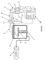
- the gaseous lithiated precursor, the carbonaceous gaseous precursor and the carrier gas and the optional doping element are each stored independently in one of the chambers labeled 2, 2 ', 2 "and 2"'.
- Figure 1 They are brought via pipelines marked 3, 3 ', 3 "and 3"' in Figure 1 at flowmeters 4, 4 ', 4 "and 4"' which make it possible to control the stoichiometry of the final compound to be obtained.
- the gaseous mixture containing the desired proportions of lithiated precursor, carbon precursor, optionally doping elements, and carrier gas is then fed through the pipe, denoted by 5.
- Figure 1 in the plasma enclosure, rated 1 in Figure 1 .
- the gaseous mixture is injected via a shower-type injection system, noted 6 in Figure 1 , in the plasma chamber 1.
- the plasma chamber 1 is maintained at a pressure of 1 mbar by a vacuum pump, denoted by 9 Figure 1 .
- the gas mixture is subjected to a radiofrequency plasma, noted 7 in Figure 1 .
- the solid electrolyte of the invention of the desired chemical composition is then deposited at the desired thickness, on the desired substrate (not shown) which is placed on a substrate holder, noted 8 in Figure 1 .
- the pressure in the plasma chamber 1 and the power of the radiofrequency plasma are controlled by means of the control devices, denoted by 10 Figure 1 .
- a plasma as an energy carrier and activator of chemical reactions allows a thorough decomposition of the precursors introduced into the chamber, in a random manner, so that the material obtained can not be described, as it is the case for a polymer, by a generic formula of the type [X] n where X represents a carbon chain "basic brick" and n the distribution of this brick. Thus, the large-scale order is not preserved.
- the material obtained is amorphous and glassy. The absence of a long polymer chain explains the absence of glass transition temperature and recrystallization phenomenon at the origin of the instabilities generally observed in polymer electrolytes.
- a solid electrolyte of formula C 38 O 21 H 22 L i19 was obtained by injection into the plasma chamber of a gaseous mixture containing 500 sccm (standard cm 3 per minute) of tetrahydrofuran (THF), of 10 sccm of lithium terbutoxide (LiTBO) and 200 sccm of helium.
- THF tetrahydrofuran
- LiTBO lithium terbutoxide
- the entire gas mixture is injected into the plasma chamber 1 and subjected to a 13.56 MHz radiofrequency plasma 7 with a power of 100 watts for 20 minutes.
- the overall pressure in the plasma chamber 1 is maintained at 1 mbar.
- the hardness of the electrolyte obtained was 2.3 GPa
- Example 1 The solid electrolyte of the invention obtained in Example 1 as well as the most widespread polymer electrolyte in the prior art which is polyethylene oxide (PEO) were analyzed by differential scanning calorimetry.
- PEO polyethylene oxide
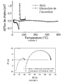
- the Figure 2 represents the curves obtained as a function of temperature.
- the differential calorimetry curve of the polyethylene oxide has a clearly defined glass transition peak at a temperature of 60 ° C while no significant change is observed with the solid electrolyte of the invention.
- the lithiated vitreous organic electrolytes of the invention make it possible to solve the problem of the thermal stability of the solid electrolyte.
- Example 3 Demonstration of the influence of the degree of crosslinking of the electrolyte according to the invention on its conductivity.
- a solid electrolyte having the same formula as the solid electrolyte of Example 1 was prepared in the same manner as in Example 1, except the plasma power which is 300 W for 20 minutes, which led to obtaining an electrolyte having a hardness of 20 GPa.
- the figure 3 represents the impedance curves obtained.
- the ionic conductivity associated with the electrolyte obtained in Example 1 is 3.10 -6 S / cm whereas this ionic conductivity drops to 2.10 -7 S / cm with the electrolyte obtained in this example 3.
- the hardness of the electrolyte of the invention should be maintained between 0.5 and 20 GPa, inclusive.
- Example 4 Manufacture of a planar microbattery.
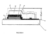
- FIG. 4 An example of a planar microbattery is shown schematically in Figure 4 .
- the silicon substrate 11 provided with its two gold current collectors (12, 13) is coated with the V 2 O 5 layer constituting the cathode, by a method known in the art such as DC or RF sputtering from a vanadium or V 2 O 5 target in the presence of oxygen.
- the electrolyte is then deposited by the technique described in Example 1 above. Then, the anode is deposited by vacuum evaporation of a lithium source.
- the assembly is encapsulated in poly-para-xylene or parylene.
- Example 5 Manufacture of a three-dimensional microbattery.
- the three-dimensional architecture of the microbattery makes it possible to increase the active storage area while maintaining an identical apparent surface.
- the use of the solid electrolyte of the invention is particularly suitable in this type of architecture that requires depositing the constituent materials of the microbattery in a consistent manner.
- the Figure 5 is a schematic representation of a microbattery with three-dimensional architecture.
- the three-dimensional architecture microbattery consists of a silicon substrate, noted 21 in Figure 5 coated with a layer of gold cathode current collector material, noted 22 in Figure 5 .
- V 2 O 5 which is the cathode
- This vanadium oxide layer 23 is deposited in a three-dimensional pattern by a method known in the art, such as a DC or RF sputtering from a vanadium or V 2 O 5 target in the presence of oxygen. This layer 23 is then textured by photolithography techniques.
- an electrolyte according to the invention is then deposited by the technique described in Example 1 so as to follow the three-dimensional pattern of the cathode layer 23.
- a layer of lithium anode is deposited on the solid electrolyte layer 24 of the invention by vacuum evaporation of a lithium source.
- an anodic current collector layer in gold is deposited on the anode still respecting the three-dimensional pattern obtained through the photolithographic texturing of the cathode layer 23 V 2 O 5 .
- Example 6 Production of an electrochromic system.
- the organic glass electrolytes of the invention can also be used in electrochromic systems.
- the application of a voltage makes it possible to insert or disinsert a cation (for example lithium) of a material whose color changes with the oxidation state.
- a cation for example lithium
- This material is in contact with an electrolyte that provides the cation source.
Landscapes
- Chemical & Material Sciences (AREA)
- Chemical Kinetics & Catalysis (AREA)
- General Chemical & Material Sciences (AREA)
- Engineering & Computer Science (AREA)
- Electrochemistry (AREA)
- Manufacturing & Machinery (AREA)
- Inorganic Chemistry (AREA)
- Mechanical Engineering (AREA)
- Materials Engineering (AREA)
- Metallurgy (AREA)
- Organic Chemistry (AREA)
- Physics & Mathematics (AREA)
- Condensed Matter Physics & Semiconductors (AREA)
- General Physics & Mathematics (AREA)
- Secondary Cells (AREA)
- Glass Compositions (AREA)
- Conductive Materials (AREA)
- Battery Electrode And Active Subsutance (AREA)
- Joining Of Glass To Other Materials (AREA)
Description
- L'invention concerne un électrolyte solide, un procédé pour sa fabrication ainsi que des dispositifs le comprenant.
- Les microbatteries au lithium sont utilisées dans des dispositifs électroniques de petites tailles ainsi que dans des dispositifs semi-conducteurs.
- L'électrolyte est un élément très influent sur les performances électriques de ces microbatteries.
- En effet, les défaillances observées lors du cyclage sont souvent liées à une dégradation électrochimique de l'électrolyte au contact du lithium.
- Les performances des microbatteries sont étroitement liées aux propriétés électriques de l'électrolyte, telles que la conductivité ionique et électronique.
- Ces microbatteries sont utilisées dans les cartes à puces, les étiquettes intelligentes, l'alimentation d'horloges internes et de microsystèmes.
- Toutes ces applications imposent que toutes les couches nécessaires au fonctionnement de la batterie soient, d'une part, solides et, d'autre part, fabriquées avec des techniques compatibles avec les procédés industriels de la microélectronique.
- Parmi les électrolytes solides on distingue deux familles: les polymères et les verres.
- Dans les électrolytes polymères solides, un sel de lithium est directement dissous dans la matrice polymère. La conductivité ionique est communément attribuée à la mobilité des ions Li+ au sein de la matrice amorphe du polymère solide.
- Cependant les électrolytes polymères solides présentent une basse température de transition vitreuse, ce qui génère la formation de zones cristallines susceptibles de piéger les ions Li+ et d'inhiber leur mobilité.
- De plus, la méthode d'élaboration des électrolytes polymères ne permet pas la réalisation de dépôts conformes aux substrats, c'est-à-dire ayant la même épaisseur en tous points du substrat.
- C'est pour ces deux raisons que l'électrolyte aujourd'hui communément employé dans la réalisation d'une microbatterie est un verre.
- Par verre, on entend un matériau amorphe.
- Parmi les verres décrits dans l'art antérieur, seuls les verres inorganiques tels que le LiPON (Lithium Phosphore OxyNitrure), le LiSON (Lithium Soufre OxyNitrure), LiSiPON (Lithium Silicium Phosphore OxyNitrure) sont utilisés comme électrolytes.
- Dans cette famille, le LiPON est l'électrolyte solide le plus utilisé dans les microbatteries actuelles car il présente une bonne stabilité électrochimique face au lithium. Cependant, il a une conductivité ionique relativement faible, de l'ordre de 2 x 10⁻⁶ S.cm-1 à température ambiante, comparée à celle de certains électrolytes polymères.
- Par ailleurs, les verres organiques tels que le carbone amorphe (a-CxHy) ou les PDMS-like (SiOxCyHz) sont couramment utilisés en microélectronique. Mais dans ce cas, ils sont employés comme isolants dans les niveaux d'interconnexions et non comme un verre organique électrolytique.
- La demande PCT
WO 2006/059794 A divulgue une batterie secondaire aux ions lithium tout solide qui comprend comme électrolyte une substance inorganique comprenant des cristaux conducteurs d'ions lithium. - Le document Journal of Power Sources, vol. 122, no. 2, 23 juillet 2003, pages 174-180, XP004437060, décrit une méthode de préparation d'un film mince d'électrolyte solide de type Li-V-Si-O pour batterie secondaire aux ions lithium tout solide.
- Le document Journal of the Electrochemical Society, vol. 144, no. 2, février 1997, pages 524-532, XP002459575, décrit la préparation et les propriétés d'un film mince d'électrolyte au lithium constitué par du Lithium Phosphore Oxynitrure (LiPON).
- La demande de
brevet français n°2 601 017 - La demande de
brevet français n°2 536 740 - Cependant, aucun de ces documents ne décrit un électrolyte solide comprenant à la fois des ions lithium et des oxydes ainsi qu'une partie organique comprenant du carbone et de l'hydrogène.
- Pour pallier les inconvénients des électrolytes solides pour microbatteries au lithium de l'art antérieur, l'invention propose un matériau électrolytique, c'est-à-dire permettant la conduction des ions lithium, déposable de façon conforme, stable à température ambiante et possédant une conductivité ionique supérieure à 1 x 10⁻⁶ S.cm-1.
- A cet effet, l'invention propose un électrolyte solide, amorphe, qui est un verre organique de formule I suivante:
SivOwCxHyLiz Formule I
dans laquelle v, w, x,y et z sont des pourcentages atomiques avec - 0 ≤ v ≤ 40,
- 5 ≤ w ≤ 50,
- x > 12,
- 10 ≤ y ≤ 40,
- 1 ≤ z ≤ 70, et
- 95% ≤ v+w+x+y+z ≤ 100.
- L'électrolyte solide de l'invention se distingue des électrolytes polymères de l'art antérieur en ce qu'il ne s'agit pas d'un polymère et qu'il ne possède donc pas de température de transition vitreuse.
- L'électrolyte selon l'invention se distingue des électrolytes qui sont des verres de l'art antérieur par sa composition chimique : il contient du carbone et donc une phase organique.
- De tels matériaux amorphes, solides, du type verre organique ne sont, a priori, pas favorables pour obtenir de bons électrolytes dans la mesure où la stabilité de la partie organique vis-à-vis du lithium n'est généralement pas bonne.
- Cependant, on a maintenant découvert que la stabilité chimique de l'électrolyte de l'invention vis-à-vis du lithium était augmentée lorsque le niveau de réticulation de l'électrolyte solide de l'invention était augmenté, ce niveau étant caractérisé par le niveau de dureté du matériau.
- Cependant, l'augmentation de la réticulation bien qu'augmentant la stabilité de l'électrolyte de l'invention vis-à-vis du lithium réduit en même temps sa conduction ionique.
- On pense, sans vouloir être lié par cette théorie, que la réduction de cette conduction ionique est due à l'augmentation de la densité du matériau.
- Mais, on a également découvert que la présence de la phase organique dans l'électrolyte solide de l'invention permet une relaxation du réseau favorisant la conduction ionique.
- Ainsi, lorsque l'électrolyte solide de l'invention contient plus de 12 % atomique de carbone, de préférence entre 20 et 40 % atomique de carbone, et une dureté supérieure ou égale à 0,5 GPa, mais inférieure à 20 GPa, l'électrolyte solide amorphe obtenu est à la fois stable chimiquement vis-à-vis du lithium, et présente de bonnes propriétés de conduction ionique.
- La dureté de l'électrolyte solide de l'invention a été mesurée par nanoindentation.
- A cet effet, on utilise un appareil de mesure de nanodureté CSM en mode multicycles en continu (continuous multicyle mode), en utilisant un embout d'indentation Berkovich.
- La pointe de l'embout d'indentation, placée sur la surface dont la dureté est à mesurer, est entraînée dans l'échantillon en appliquant une charge. La charge est ensuite diminuée jusqu'à ce que la relaxation partielle ou complète du matériau se produise. La courbe charge-profondeur est ensuite utilisée pour calculer les propriétés mécaniques telles que la dureté et le module d'élasticité.
- Ici, une charge initiale de 1 mN augmentée jusqu'à 10 mN a été utilisée jusqu'à obtenir une empreinte, laissée par l'application de la charge, de 100 à 200 nm. Toutes les mesures ont été effectuées sur des échantillons de 2 µm d'épaisseur.
- Plus précisément, le verre électrolytique organique de l'invention contient, en pourcentage atomique, plus de 12 % de carbone, de préférence entre 20 et 40 % de carbone, entre 1 et 70 % de lithium, de préférence entre 20 et 40 % de lithium, entre 5 et 50 % d'oxygène, de préférence entre 15 et 30 % d'oxygène, et entre 0 et 40 % de silicium, de préférence entre 0 et 15 % de silicium, et entre 10 et 40% d'hydrogène, de préférence entre 15 et 30 % d'hydrogène, la somme des pourcentages atomiques de carbone, lithium, oxygène, silicium et hydrogène étant au moins égale à 95%.
- En effet, bien que le verre électrolytique organique de l'invention puisse ne comprendre que du carbone, du lithium, de l'oxygène, du silicium et de l'hydrogène, on peut également prévoir de le doper par ajout de matériaux tels que le fluor, le bore, le phosphore ou l'azote ou leurs mélanges pour lui conférer une plus grande résistance chimique vis-à-vis de l'atmosphère ou une meilleure couverture de marche.
- Ainsi, l'électrolyte de l'invention peut comprendre en outre au plus 5% atomique d'au moins un élément dopant.
- L'électrolyte de l'invention est obtenu par dépôt chimique en phase vapeur par plasma d'un précurseur carboné gazeux auquel est ajouté un précurseur gazeux lithié et un gaz porteur neutre tel que l'hélium.
- Le précurseur carboné permet d'obtenir une matrice vitreuse du type a-CxHy ou SiOxCyHz et peut être de l'héxaméthyldisiloxane (HMDSO), du tétraéthyloxysilane (TEOS), de l'octaméthylcyclotétrasiloxane (OMCTSO), C7H8, C6H12, CH4, C9H10, C2H2, te tétrahydrofurane (THF) ou un mélange de un ou plusieurs de ces précurseurs carbonés.
- Le précurseur lithié, pour fonctionnaliser la matrice vitreuse du type carbone amorphe ou SiOxCyHz, est de préférence du lithium héxaméthyledisilazane (LiHMDS), du lithium tétraméthylheptanedionate (LiTMHD), du lithium terbutoxyde (LiTBO), du lithium acétylacétonate (LiAcac) ou un mélange de l'un ou plusieurs de ces précurseurs lithiés.
- L'électrolyte de l'invention répond aux exigences des microbatteries tout-solide au lithium, aux exigences des systèmes électrochromes et en général de tout accumulateur au lithium.
- Son procédé de fabrication est un procédé compatible avec les procédés utilisés dans la microélectronique qui permet la réalisation d'un dépôt à une basse température, c'est-à-dire à une température inférieure à 300°C et, de plus le procédé permet de contrôler les épaisseurs déposées d'électrolyte solide au nanomètre près et ce à des vitesses de dépôts supérieures à 5 µm par heure.
- L'invention sera mieux comprise et d'autres détails et avantages de celle-ci apparaîtront plus clairement à la lecture de la description explicative qui suit et qui est faite en référence aux figures dans lesquelles:
- la
Figure 1 représente schématiquement un appareil de dépôt chimique en phase vapeur par plasma permettant le dépôt et la fabrication de l'électrolyte de l'invention, - la
Figure 2 représente les courbes d'analyse calorimétrique différentielle d'un électrolyte polymère classique et d'un électrolyte organique vitreux selon l'invention, - La
Figure 3 représente les mesures de spectroscopie d'impédance réalisées sur des électrolytes organiques vitreux de l'invention présentant respectivement une dureté de 2,3 GPa et de 20 GPa. - la
Figure 4 représente schématiquement une vue en coupe d'une microbatterie planaire au lithium comprenant un électrolyte de l'invention et, - La
Figure 5 est une représentation schématique d'une microbatterie au lithium à architecture tridimensionnelle comprenant une couche d'électrolyte selon l'invention. - Tout d'abord, le procédé de fabrication de l'électrolyte de l'invention sera décrit en référence à la
Figure 1 . - Le précurseur lithié gazeux, le précurseur carboné gazeux et le gaz porteur ainsi que l'éventuel élément dopant sont stockés chacun indépendamment dans une des enceintes notées 2, 2',2" et 2"' en
Figure 1 . Ils sont amenés via les canalisations notées 3, 3', 3" et 3"' enFigure 1 , à des débitmètres notés 4, 4', 4" et 4"' qui permettent de contrôler la stoechiométrie du composé final à obtenir. - Le mélange gazeux, contenant les proportions souhaitées de précurseur lithié, de précurseur carboné, éventuellement d'éléments dopants, et de gaz porteur est ensuite amené par la canalisation, notée 5 en
Figure 1 , dans l'enceinte plasma, notée 1 enFigure 1 . - Le mélange gazeux est injecté via un système d'injection de type douche, noté 6 en
Figure 1 , dans l'enceinte plasma 1. L'enceinte plasma 1 est maintenue à une pression de 1 mbar par une pompe à vide, notée 9 enFigure 1 . - Puis le mélange gazeux est soumis à un plasma radiofréquence, noté 7 en
Figure 1 . L'électrolyte solide de l'invention de la composition chimique voulue est alors déposé à l'épaisseur voulue, sur le substrat voulu (non représenté) qui est placé sur un porte substrat, noté 8 enFigure 1 . - La pression dans l'enceinte plasma 1 et la puissance du plasma radiofréquence sont contrôlées grâce aux appareils de contrôle, notés 10 en
Figure 1 . - L'utilisation d'un plasma comme vecteur d'énergie et activateur des réactions chimiques permet une décomposition poussée des précurseurs introduits dans l'enceinte, et ce d'une manière aléatoire, ce qui fait que le matériau obtenu ne peut pas être décrit, comme c'est le cas pour un polymère, par une formule générique de type [X]n où X représente une chaîne carbonée "brique de base" et n la répartition de cette brique. Ainsi, l'ordre à grande échelle n'est pas conservé. Le matériau obtenu est amorphe et vitreux. L'absence de longue chaîne polymère explique l'absence de température de transition vitreuse et de phénomène de recristallisation à l'origine des instabilités généralement observées dans les électrolytes polymères.
- Afin de mieux faire comprendre l'invention, on va en décrire ci-après plusieurs exemples de mise en oeuvre qui sont donnés uniquement à titre illustratif et ne doivent pas être considérés comme limitatifs de l'invention.
- En utilisant l'appareillage montré en
Figure 1 et décrit ci-dessus, un électrolyte solide de formule C38 O21 H22 Li19 a été obtenu par injection dans l'enceinte plasma d'un mélange gazeux contenant 500 sccm (cm3 standard par mn) de tétrahydrofurane (THF), de 10 sccm de lithium terbutoxyde (LiTBO) et 200 sccm d'hélium. - L'ensemble du mélange gazeux est injecté dans l'enceinte de plasma 1 et soumis à un plasma noté 7 de radiofréquence 13,56 MHz d'une puissance de 100 watts pendant 20 minutes.
- Pendant tout le dépôt, la pression globale dans l'enceinte plasma 1 est maintenue à 1 mbar.
- La dureté de l'électrolyte obtenu était de 2,3 GPa
- L'électrolyte solide de l'invention obtenu à l'exemple 1 ainsi que l'électrolyte polymère le plus répandu dans l'art antérieur qui est le polyéthylène oxyde (PEO) ont été analysés par analyse calorimétrique différentielle.
- La
Figure 2 représente les courbes obtenues en fonction de la température. - Comme on le voit en
Figure 2 , la courbe de calorimétrie différentielle du polyéthylène oxyde présente un pic de transition vitreuse clairement défini à une température de 60°C alors qu'aucun changement notable n'est observé avec l'électrolyte solide de l'invention. - En ce sens, les électrolytes organiques vitreux lithiés de l'invention permettent de résoudre le problème de la stabilité thermique de l'électrolyte solide.
- Un électrolyte solide ayant la même formule que l'électrolyte solide de l'exemple 1 a été préparé de la même manière qu'à l'exemple 1, sauf la puissance plasma qui est de 300 W pendant 20 minutes, ce qui a mené à l'obtention d'un électrolyte ayant une dureté de 20 GPa.
- Une mesure de spectroscopie d'impédance a alors été réalisée sur l'électrolyte solide obtenu de l'exemple 1 et sur l'électrolyte solide obtenu à cet exemple 3.
- La
figure 3 représente les courbes d'impédance obtenues. - Comme on le voit en
Figure 3 , la conductivité ionique associée à l'électrolyte obtenu à l'exemple 1 est de 3.10-6 S/cm alors que cette conductivité ionique chute à 2.10-7 S/cm avec l'électrolyte obtenu à cet exemple 3. - Ainsi, la dureté de l'électrolyte de l'invention doit être maintenue entre 0,5 et 20 GPa, inclus.
- Un exemple de microbatterie planaire est schématisé à la
Figure 4 . - Comme on le voit en
Figure 4 , la microbatterie planaire est constituée de l'empilement successif des couches suivantes: - un substrat en silicium noté 11 en
Figure 4 , - un collecteur de courant anodique en or noté 12 en
Figure 4 , - un collecteur de courant cathodique en or noté 13 en
Figure 4 , - une cathode en oxyde de vanadium (V2O5) notée 14 en
Figure 4 , - un électrolyte solide selon l'invention, noté 15 en
Figure 4 , - une anode en lithium, noté 16 en
Figure 4 , et - une couche d'encapsulation en parylène, notée 17 en
Figure 4 . - Pour réaliser cette microbatterie planaire, le substrat de silicium 11 muni de ses deux collecteurs de courant en or (12, 13) est revêtu de la couche en V2O5, constituant la cathode, par un procédé connu dans l'art tel qu'une pulvérisation cathodique DC ou RF à partir d'une cible de vanadium ou de V2O5 en présence d'oxygène.
- L'électrolyte est ensuite déposé par la technique décrite à l'exemple 1 ci-dessus. Puis, l'anode est déposée par évaporation sous vide d'une source de lithium.
- Enfin, l'ensemble est encapsulé dans du poly-para-xylène ou parylène.
- L'architecture à trois dimensions de la microbatterie permet d'augmenter la surface active de stockage tout en conservant une surface apparente identique. L'utilisation de l'électrolyte solide de l'invention est particulièrement adaptée dans ce genre d'architecture qui nécessite de déposer les matériaux constitutifs de la microbatterie de façon conforme.
- La
Figure 5 est une représentation schématique d'une microbatterie à architecture tridimensionnelle. - Comme on le voit en
Figure 5 , la microbatterie à architecture tridimensionnelle est constituée d'un substrat en silicium, noté 21 enFigure 5 , revêtu d'une couche d'un matériau collecteur de courant cathodique en or, notée 22 enFigure 5 . - Une couche, notée 23 en
Figure 5 , en oxyde de vanadium, V2O5, qui est la cathode, est déposée sur la couche 22. Cette couche 23 d'oxyde de vanadium est déposée selon un motif tridimensionnel par un procédé connu dans l'art, tel qu'une pulvérisation cathodique DC ou RF à partir d'une cible de vanadium ou de V2O5 en présence d'oxygène. Cette couche 23 est ensuite texturée par des techniques de photolithographie. - Une couche, notée 24 en
Figure 5 , d'un électrolyte -selon l'invention est ensuite déposée par la technique décrite à l'exemple 1 de façon à suivre le motif tridimensionnel de la couche de cathode 23. - Ensuite, une couche d'anode en lithium, notée 25 en
Figure 5 , est déposée sur la couche 24 d'électrolyte solide de l'invention par évaporation sous vide d'une source de lithium. - Enfin, une couche de collecteur de courant anodique en or, notée 26 en
Figure 5 , est déposée sur l'anode toujours en respectant le motif tridimensionnel obtenu grâce à la texturation par photolithographie de la couche 23 de cathode en V2O5. - Les électrolytes à base de verre organique de l'invention peuvent également être utilisés dans les systèmes électrochromes.
- Dans ce type de système, l'application d'une tension permet d'insérer ou de désinsérer un cation (par exemple du lithium) d'un matériau dont la coloration évolue avec l'état d'oxydation. Ce matériau est en contact avec un électrolyte qui assure la source de cation.
- Le dispositif réalisé avec l'électrolyte solide de l'invention est obtenu par exemple par l'empilement successif des couches suivantes:
- un substrat en verre,
- un collecteur de courant en oxyde d'indium et d'étain (ITO) obtenu par pulvérisation cathodique DC,
- un matériau électrochrome cathodique en WO3 obtenu par pulvérisation cathodique DC sous atmosphère d'argon + oxygène, suivie d'un recuit,
- un matériau électrolyte selon l'invention,
- un matériau électrochrome anodique en ZrO2 obtenu par pulvérisation cathodique DC,
- un collecteur de courant en ITO obtenu par pulvérisation cathodique DC, et
- une encapsulation transparente en parylène.
Claims (9)
- Electrolyte caractérisé en ce qu'il est un solide amorphe de formule I suivante:
SivOwCxHyLiz Formule I
dans laquelle v, w, x,y et z sont des pourcentages atomiques avec0 ≤ v ≤ 40,5 ≤ w ≤ 50,x > 12,10 ≤ y ≤ 40,1 ≤ z ≤ 70, et95%≤ v+w+x+y+z ≤100%. - Electrolyte selon la revendication 1, caractérisé en ce que dans la formule I:0 ≤ v ≤ 15,15 ≤ w ≤ 30,20 ≤ x ≤ 40,15 ≤ y ≤ 30, et20 ≤ z ≤ 40.
- Electrolyte selon la revendication 1 ou 2, caractérisé en ce qu'il comprend en outre au plus 5 % atomique d'au moins un élément dopant.
- Electrolyte selon la revendication 3, caractérisé en ce que ledit au moins un élément dopant est choisi dans le groupe constitué par le fluor, le bore, le phosphore, l'azote ou les mélanges de ceux-ci.
- Procédé de fabrication d'un électrolyte solide selon l'une quelconque des revendications précédentes, caractérisé en ce qu'il comprend le dépôt chimique en phase vapeur par plasma d'un mélange gazeux comprenant :- un gaz carboné précurseur,- un précurseur lithié gazeux, et- un gaz porteur neutre tel que l'hélium,sur le support voulu.
- Procédé selon la revendication 5, caractérisé en ce que ledit gaz carboné précurseur est choisi parmi l'héxaméthyldisiloxane (HMDSO), le tétraéthyloxysilane (TEOS), l'octaméthylcyclotétrasiloxane (OMCTSO), C7H8, C6H12, CH4, C9H10, C2H2, le tétrahydrofurane (THF), et leurs mélanges, et en ce que ledit précurseur lithié gazeux est choisi parmi le lithium héxaméthyledisilazane (LiHMDS), le lithium tétraméthylheptanedionate (LiTMHD), le lithium terbutoxyde (LiTBO), le lithium acétylacétonate (LiAcac) et leurs mélanges.
- Microbatterie tout solide, caractérisée en ce qu'elle comprend un électrolyte selon l'une quelconque des revendications 1 à 4 ou obtenu par le procédé selon la revendication 5 ou 6.
- Système électrochrome, caractérisé en qu'il comprend un électrolyte selon l'une quelconque des revendications 1 à 4 ou obtenu par le procédé selon la revendication 5 ou 6.
- Accumulateur au lithium, caractérisé en ce qu'il comprend un électrolyte selon l'une quelconque des revendications 1 à 4 ou obtenu par la procédé selon la revendication 5 ou 6.
Priority Applications (1)
| Application Number | Priority Date | Filing Date | Title |
|---|---|---|---|
| PL08290475T PL1995815T3 (pl) | 2007-05-25 | 2008-05-22 | Wielowarstwowy element pokrycia dachowego i sposób jego wytwarzania |
Applications Claiming Priority (1)
| Application Number | Priority Date | Filing Date | Title |
|---|---|---|---|
| FR0703723A FR2916577B1 (fr) | 2007-05-25 | 2007-05-25 | Verre organique electrolytique, son procede de fabrication et dispositif le comprenant. |
Publications (2)
| Publication Number | Publication Date |
|---|---|
| EP1995815A1 EP1995815A1 (fr) | 2008-11-26 |
| EP1995815B1 true EP1995815B1 (fr) | 2010-12-08 |
Family
ID=38686803
Family Applications (1)
| Application Number | Title | Priority Date | Filing Date |
|---|---|---|---|
| EP08290475A Active EP1995815B1 (fr) | 2007-05-25 | 2008-05-22 | Verre organique électrolytique, son procédé de fabrication et dispositif le comprenant |
Country Status (9)
| Country | Link |
|---|---|
| US (1) | US8153305B2 (fr) |
| EP (1) | EP1995815B1 (fr) |
| JP (1) | JP5258378B2 (fr) |
| CN (1) | CN101414492B (fr) |
| AT (1) | ATE491241T1 (fr) |
| DE (1) | DE602008003860D1 (fr) |
| ES (1) | ES2359034T3 (fr) |
| FR (1) | FR2916577B1 (fr) |
| PL (1) | PL1995815T3 (fr) |
Families Citing this family (9)
| Publication number | Priority date | Publication date | Assignee | Title |
|---|---|---|---|---|
| JP5503858B2 (ja) * | 2008-09-22 | 2014-05-28 | 株式会社東芝 | 非水電解質電池用負極活物質及び非水電解質電池 |
| CN101718738B (zh) * | 2009-11-06 | 2013-01-02 | 北京化工大学 | NiAl-层状双金属氢氧化物/碳纳米管复合物电极及其制备方法和应用 |
| WO2014028853A1 (fr) * | 2012-08-16 | 2014-02-20 | The Regents Of The University Of California | Micro-batteries 3d à base d'électrolyte à couches minces |
| US9406969B2 (en) * | 2013-03-15 | 2016-08-02 | Johnson & Johnson Vision Care, Inc. | Methods and apparatus to form three-dimensional biocompatible energization elements |
| KR20160101932A (ko) * | 2013-12-25 | 2016-08-26 | 신에쓰 가가꾸 고교 가부시끼가이샤 | 비수 전해질 2차 전지용 부극 활물질 및 그의 제조 방법 |
| JP6114179B2 (ja) * | 2013-12-25 | 2017-04-12 | 信越化学工業株式会社 | 非水電解質二次電池用負極活物質及びその製造方法 |
| JP6114178B2 (ja) * | 2013-12-25 | 2017-04-12 | 信越化学工業株式会社 | 非水電解質二次電池用負極活物質及びその製造方法 |
| DE102015121103A1 (de) * | 2015-12-03 | 2017-06-08 | Technische Universität Darmstadt | Verfahren zur Herstellung einer Beschichtung auf einer Oberfläche eines Substrats |
| JP7525475B2 (ja) * | 2019-03-26 | 2024-07-30 | 株式会社半導体エネルギー研究所 | 固体二次電池およびその作製方法 |
Family Cites Families (6)
| Publication number | Priority date | Publication date | Assignee | Title |
|---|---|---|---|---|
| US4465744A (en) * | 1982-11-30 | 1984-08-14 | The United States Of America As Represented By The United States Department Of Energy | Super ionic conductive glass |
| FR2601017B1 (fr) * | 1986-07-02 | 1988-09-23 | Centre Nat Rech Scient | Nouvelles compositions a base de derives de silice modifiee par des groupements organiques, leur preparation et leur application, notamment comme conducteurs protoniques |
| EP1328996A2 (fr) * | 2000-10-06 | 2003-07-23 | E.I. Du Pont De Nemours & Company Incorporated | Pile lithium ou pile lithium ion de haute performance |
| JP4147787B2 (ja) * | 2002-02-28 | 2008-09-10 | 凸版印刷株式会社 | イオン伝導体 |
| TW200638568A (en) * | 2004-12-02 | 2006-11-01 | Ohara Kk | All solid lithium ion secondary battery and a solid electrolyte therefor |
| JP4631689B2 (ja) * | 2005-12-14 | 2011-02-16 | ダイキン工業株式会社 | イオン伝導体 |
-
2007
- 2007-05-25 FR FR0703723A patent/FR2916577B1/fr not_active Expired - Fee Related
-
2008
- 2008-05-07 US US12/116,585 patent/US8153305B2/en not_active Expired - Fee Related
- 2008-05-15 JP JP2008127898A patent/JP5258378B2/ja not_active Expired - Fee Related
- 2008-05-19 CN CN2008100932532A patent/CN101414492B/zh not_active Expired - Fee Related
- 2008-05-22 DE DE602008003860T patent/DE602008003860D1/de active Active
- 2008-05-22 EP EP08290475A patent/EP1995815B1/fr active Active
- 2008-05-22 PL PL08290475T patent/PL1995815T3/pl unknown
- 2008-05-22 ES ES08290475T patent/ES2359034T3/es active Active
- 2008-05-22 AT AT08290475T patent/ATE491241T1/de not_active IP Right Cessation
Also Published As
| Publication number | Publication date |
|---|---|
| FR2916577B1 (fr) | 2009-11-27 |
| ATE491241T1 (de) | 2010-12-15 |
| US8153305B2 (en) | 2012-04-10 |
| DE602008003860D1 (de) | 2011-01-20 |
| FR2916577A1 (fr) | 2008-11-28 |
| JP2008293974A (ja) | 2008-12-04 |
| CN101414492B (zh) | 2012-02-08 |
| PL1995815T3 (pl) | 2011-05-31 |
| EP1995815A1 (fr) | 2008-11-26 |
| JP5258378B2 (ja) | 2013-08-07 |
| US20080305399A1 (en) | 2008-12-11 |
| ES2359034T3 (es) | 2011-05-17 |
| CN101414492A (zh) | 2009-04-22 |
Similar Documents
| Publication | Publication Date | Title |
|---|---|---|
| EP1995815B1 (fr) | Verre organique électrolytique, son procédé de fabrication et dispositif le comprenant | |
| KR101612057B1 (ko) | 박막 전지 및 이를 제조하기 위한 방법 | |
| CA2848580C (fr) | Procede de preparation d'electrode a partir d'un materiau poreux, electrode ainsi obtenue et systeme electrochimique correspondant | |
| EP2715839B1 (fr) | ANODES DE BATTERIES Li-ION | |
| US20120028129A1 (en) | Method for manufacturing solid electrolyte battery and solid electrolyte battery | |
| FR2638764A1 (fr) | Element composite comportant une couche en chalcogenure ou oxychalcogenure de titane, utilisable en particulier comme electrode positive dans une cellule electrochimique en couches minces | |
| Zhu et al. | A comparison of solid electrolyte interphase formation and evolution on highly oriented pyrolytic and disordered graphite negative electrodes in lithium‐ion batteries | |
| WO2009112714A2 (fr) | Procede de fabrication d'une electrode a base de silicium, electrode a base de silicium et batterie au lithium comprenant une telle electrode | |
| EP2134883A1 (fr) | Cible de pulverisation cathodique d'oxynitrure | |
| Arie et al. | Electrochemical characteristics of lithium metal anodes with diamond like carbon film coating layer | |
| EP4165697A1 (fr) | Electrode traitee en surface, protection des electrolytes solides, les elements, modules et batteries la comprenant | |
| Julien et al. | Lithium insertion in indium selenide films: application to microbatteries | |
| CA2288937A1 (fr) | Materiau d'electrode positive a base d'oxysulfure de titane pour generateur electrochimique et son procede de preparation | |
| EP4256633A1 (fr) | Electrode pour batterie li-ion quasi solide | |
| US20210167352A1 (en) | Transparent anode thin film comprising a transparent anode active material, lithium thin film secondary battery, and the method for manufacturing the same | |
| Bao et al. | Metal buffer layer inserted switchable mirrors | |
| Fujikake et al. | Amorphous Ge/LiAlGePO Composite Anodes with a Multistacking Structure Developed via Co‐Sputtering for High‐Capacity Li+‐Ion Batteries | |
| FR2873856A1 (fr) | Procede pour augmenter la conductivite ionique d'un electrolyte solide lithie, electrolyte susceptible d'etre obtenu par ce procede et ses utilisations | |
| EP1680829B1 (fr) | Electrolyte solide, notamment pour cellule electrochimique en couches minces, et un procede de fabrication | |
| CN115210902A (zh) | 方法 | |
| FR3112029A1 (fr) | Electrode traitee en surface, les elements, modules et batteries la comprenant | |
| WO2026022024A1 (fr) | Électrolyte solide comprenant un revêtement métallique et procédés de fabrication d'un tel électrolyte solide | |
| Aribia et al. | In Situ Lithiated ALD Niobium Oxide for Improved Long Term Cycling of LiCoO2 Cathodes: A Thin-Film Model Study | |
| WO2022220675A1 (fr) | Anode à base de carbure de silicium amorphe hydrogéné pour application dans des batteries au lithium-ion | |
| CH721993A2 (fr) | Électrolyte solide comprenant un revêtement métallique et procédés de fabrication d'un tel électrolyte solide |
Legal Events
| Date | Code | Title | Description |
|---|---|---|---|
| PUAI | Public reference made under article 153(3) epc to a published international application that has entered the european phase |
Free format text: ORIGINAL CODE: 0009012 |
|
| AK | Designated contracting states |
Kind code of ref document: A1 Designated state(s): AT BE BG CH CY CZ DE DK EE ES FI FR GB GR HR HU IE IS IT LI LT LU LV MC MT NL NO PL PT RO SE SI SK TR |
|
| AX | Request for extension of the european patent |
Extension state: AL BA MK RS |
|
| 17P | Request for examination filed |
Effective date: 20090424 |
|
| 17Q | First examination report despatched |
Effective date: 20090617 |
|
| AKX | Designation fees paid |
Designated state(s): AT BE BG CH CY CZ DE DK EE ES FI FR GB GR HR HU IE IS IT LI LT LU LV MC MT NL NO PL PT RO SE SI SK TR |
|
| AXX | Extension fees paid |
Extension state: RS Payment date: 20090424 Extension state: MK Payment date: 20090424 Extension state: BA Payment date: 20090424 Extension state: AL Payment date: 20090424 |
|
| RIC1 | Information provided on ipc code assigned before grant |
Ipc: H01M 4/38 20060101ALN20100205BHEP Ipc: H01M 10/0562 20100101AFI20100205BHEP Ipc: H01M 10/052 20100101ALI20100205BHEP Ipc: G02F 1/15 20060101ALI20100205BHEP Ipc: H01M 4/485 20100101ALN20100205BHEP Ipc: H01M 10/04 20060101ALI20100205BHEP |
|
| RAP1 | Party data changed (applicant data changed or rights of an application transferred) |
Owner name: COMMISSARIAT A L'ENERGIE ATOMIQUE ET AUX ENERGIES |
|
| GRAP | Despatch of communication of intention to grant a patent |
Free format text: ORIGINAL CODE: EPIDOSNIGR1 |
|
| GRAS | Grant fee paid |
Free format text: ORIGINAL CODE: EPIDOSNIGR3 |
|
| GRAA | (expected) grant |
Free format text: ORIGINAL CODE: 0009210 |
|
| AK | Designated contracting states |
Kind code of ref document: B1 Designated state(s): AT BE BG CH CY CZ DE DK EE ES FI FR GB GR HR HU IE IS IT LI LT LU LV MC MT NL NO PL PT RO SE SI SK TR |
|
| AX | Request for extension of the european patent |
Extension state: AL BA MK RS |
|
| REG | Reference to a national code |
Ref country code: GB Ref legal event code: FG4D Free format text: NOT ENGLISH |
|
| REG | Reference to a national code |
Ref country code: CH Ref legal event code: EP |
|
| REG | Reference to a national code |
Ref country code: IE Ref legal event code: FG4D |
|
| REF | Corresponds to: |
Ref document number: 602008003860 Country of ref document: DE Date of ref document: 20110120 Kind code of ref document: P |
|
| REG | Reference to a national code |
Ref country code: NL Ref legal event code: VDEP Effective date: 20101208 |
|
| PG25 | Lapsed in a contracting state [announced via postgrant information from national office to epo] |
Ref country code: LT Free format text: LAPSE BECAUSE OF FAILURE TO SUBMIT A TRANSLATION OF THE DESCRIPTION OR TO PAY THE FEE WITHIN THE PRESCRIBED TIME-LIMIT Effective date: 20101208 Ref country code: NO Free format text: LAPSE BECAUSE OF FAILURE TO SUBMIT A TRANSLATION OF THE DESCRIPTION OR TO PAY THE FEE WITHIN THE PRESCRIBED TIME-LIMIT Effective date: 20110308 |
|
| REG | Reference to a national code |
Ref country code: ES Ref legal event code: FG2A Ref document number: 2359034 Country of ref document: ES Kind code of ref document: T3 Effective date: 20110517 |
|
| LTIE | Lt: invalidation of european patent or patent extension |
Effective date: 20101208 |
|
| PG25 | Lapsed in a contracting state [announced via postgrant information from national office to epo] |
Ref country code: SE Free format text: LAPSE BECAUSE OF FAILURE TO SUBMIT A TRANSLATION OF THE DESCRIPTION OR TO PAY THE FEE WITHIN THE PRESCRIBED TIME-LIMIT Effective date: 20101208 Ref country code: SI Free format text: LAPSE BECAUSE OF FAILURE TO SUBMIT A TRANSLATION OF THE DESCRIPTION OR TO PAY THE FEE WITHIN THE PRESCRIBED TIME-LIMIT Effective date: 20101208 Ref country code: BG Free format text: LAPSE BECAUSE OF FAILURE TO SUBMIT A TRANSLATION OF THE DESCRIPTION OR TO PAY THE FEE WITHIN THE PRESCRIBED TIME-LIMIT Effective date: 20110308 Ref country code: LV Free format text: LAPSE BECAUSE OF FAILURE TO SUBMIT A TRANSLATION OF THE DESCRIPTION OR TO PAY THE FEE WITHIN THE PRESCRIBED TIME-LIMIT Effective date: 20101208 Ref country code: HR Free format text: LAPSE BECAUSE OF FAILURE TO SUBMIT A TRANSLATION OF THE DESCRIPTION OR TO PAY THE FEE WITHIN THE PRESCRIBED TIME-LIMIT Effective date: 20101208 Ref country code: NL Free format text: LAPSE BECAUSE OF FAILURE TO SUBMIT A TRANSLATION OF THE DESCRIPTION OR TO PAY THE FEE WITHIN THE PRESCRIBED TIME-LIMIT Effective date: 20101208 Ref country code: CY Free format text: LAPSE BECAUSE OF FAILURE TO SUBMIT A TRANSLATION OF THE DESCRIPTION OR TO PAY THE FEE WITHIN THE PRESCRIBED TIME-LIMIT Effective date: 20101208 Ref country code: FI Free format text: LAPSE BECAUSE OF FAILURE TO SUBMIT A TRANSLATION OF THE DESCRIPTION OR TO PAY THE FEE WITHIN THE PRESCRIBED TIME-LIMIT Effective date: 20101208 Ref country code: AT Free format text: LAPSE BECAUSE OF FAILURE TO SUBMIT A TRANSLATION OF THE DESCRIPTION OR TO PAY THE FEE WITHIN THE PRESCRIBED TIME-LIMIT Effective date: 20101208 |
|
| REG | Reference to a national code |
Ref country code: PL Ref legal event code: T3 |
|
| REG | Reference to a national code |
Ref country code: IE Ref legal event code: FD4D |
|
| PG25 | Lapsed in a contracting state [announced via postgrant information from national office to epo] |
Ref country code: PT Free format text: LAPSE BECAUSE OF FAILURE TO SUBMIT A TRANSLATION OF THE DESCRIPTION OR TO PAY THE FEE WITHIN THE PRESCRIBED TIME-LIMIT Effective date: 20110408 Ref country code: GR Free format text: LAPSE BECAUSE OF FAILURE TO SUBMIT A TRANSLATION OF THE DESCRIPTION OR TO PAY THE FEE WITHIN THE PRESCRIBED TIME-LIMIT Effective date: 20110309 Ref country code: EE Free format text: LAPSE BECAUSE OF FAILURE TO SUBMIT A TRANSLATION OF THE DESCRIPTION OR TO PAY THE FEE WITHIN THE PRESCRIBED TIME-LIMIT Effective date: 20101208 Ref country code: IE Free format text: LAPSE BECAUSE OF FAILURE TO SUBMIT A TRANSLATION OF THE DESCRIPTION OR TO PAY THE FEE WITHIN THE PRESCRIBED TIME-LIMIT Effective date: 20101208 Ref country code: CZ Free format text: LAPSE BECAUSE OF FAILURE TO SUBMIT A TRANSLATION OF THE DESCRIPTION OR TO PAY THE FEE WITHIN THE PRESCRIBED TIME-LIMIT Effective date: 20101208 Ref country code: IS Free format text: LAPSE BECAUSE OF FAILURE TO SUBMIT A TRANSLATION OF THE DESCRIPTION OR TO PAY THE FEE WITHIN THE PRESCRIBED TIME-LIMIT Effective date: 20110408 |
|
| PG25 | Lapsed in a contracting state [announced via postgrant information from national office to epo] |
Ref country code: RO Free format text: LAPSE BECAUSE OF FAILURE TO SUBMIT A TRANSLATION OF THE DESCRIPTION OR TO PAY THE FEE WITHIN THE PRESCRIBED TIME-LIMIT Effective date: 20101208 Ref country code: SK Free format text: LAPSE BECAUSE OF FAILURE TO SUBMIT A TRANSLATION OF THE DESCRIPTION OR TO PAY THE FEE WITHIN THE PRESCRIBED TIME-LIMIT Effective date: 20101208 |
|
| PLBE | No opposition filed within time limit |
Free format text: ORIGINAL CODE: 0009261 |
|
| STAA | Information on the status of an ep patent application or granted ep patent |
Free format text: STATUS: NO OPPOSITION FILED WITHIN TIME LIMIT |
|
| PG25 | Lapsed in a contracting state [announced via postgrant information from national office to epo] |
Ref country code: DK Free format text: LAPSE BECAUSE OF FAILURE TO SUBMIT A TRANSLATION OF THE DESCRIPTION OR TO PAY THE FEE WITHIN THE PRESCRIBED TIME-LIMIT Effective date: 20101208 |
|
| 26N | No opposition filed |
Effective date: 20110909 |
|
| BERE | Be: lapsed |
Owner name: COMMISSARIAT A L'ENERGIE ATOMIQUE ET AUX ENERGIES Effective date: 20110531 |
|
| PG25 | Lapsed in a contracting state [announced via postgrant information from national office to epo] |
Ref country code: MT Free format text: LAPSE BECAUSE OF FAILURE TO SUBMIT A TRANSLATION OF THE DESCRIPTION OR TO PAY THE FEE WITHIN THE PRESCRIBED TIME-LIMIT Effective date: 20101208 Ref country code: MC Free format text: LAPSE BECAUSE OF NON-PAYMENT OF DUE FEES Effective date: 20110531 |
|
| REG | Reference to a national code |
Ref country code: DE Ref legal event code: R097 Ref document number: 602008003860 Country of ref document: DE Effective date: 20110909 |
|
| PG25 | Lapsed in a contracting state [announced via postgrant information from national office to epo] |
Ref country code: BE Free format text: LAPSE BECAUSE OF NON-PAYMENT OF DUE FEES Effective date: 20110531 |
|
| REG | Reference to a national code |
Ref country code: CH Ref legal event code: PL |
|
| PG25 | Lapsed in a contracting state [announced via postgrant information from national office to epo] |
Ref country code: CH Free format text: LAPSE BECAUSE OF NON-PAYMENT OF DUE FEES Effective date: 20120531 Ref country code: LI Free format text: LAPSE BECAUSE OF NON-PAYMENT OF DUE FEES Effective date: 20120531 |
|
| PG25 | Lapsed in a contracting state [announced via postgrant information from national office to epo] |
Ref country code: LU Free format text: LAPSE BECAUSE OF NON-PAYMENT OF DUE FEES Effective date: 20110522 |
|
| PG25 | Lapsed in a contracting state [announced via postgrant information from national office to epo] |
Ref country code: TR Free format text: LAPSE BECAUSE OF FAILURE TO SUBMIT A TRANSLATION OF THE DESCRIPTION OR TO PAY THE FEE WITHIN THE PRESCRIBED TIME-LIMIT Effective date: 20101208 |
|
| PG25 | Lapsed in a contracting state [announced via postgrant information from national office to epo] |
Ref country code: HU Free format text: LAPSE BECAUSE OF FAILURE TO SUBMIT A TRANSLATION OF THE DESCRIPTION OR TO PAY THE FEE WITHIN THE PRESCRIBED TIME-LIMIT Effective date: 20101208 |
|
| REG | Reference to a national code |
Ref country code: FR Ref legal event code: PLFP Year of fee payment: 8 |
|
| REG | Reference to a national code |
Ref country code: FR Ref legal event code: PLFP Year of fee payment: 9 |
|
| REG | Reference to a national code |
Ref country code: FR Ref legal event code: PLFP Year of fee payment: 10 |
|
| REG | Reference to a national code |
Ref country code: FR Ref legal event code: PLFP Year of fee payment: 11 |
|
| PGFP | Annual fee paid to national office [announced via postgrant information from national office to epo] |
Ref country code: ES Payment date: 20200616 Year of fee payment: 13 |
|
| PGFP | Annual fee paid to national office [announced via postgrant information from national office to epo] |
Ref country code: PL Payment date: 20200417 Year of fee payment: 13 Ref country code: IT Payment date: 20200511 Year of fee payment: 13 |
|
| PGFP | Annual fee paid to national office [announced via postgrant information from national office to epo] |
Ref country code: FR Payment date: 20210531 Year of fee payment: 14 Ref country code: DE Payment date: 20210507 Year of fee payment: 14 |
|
| PGFP | Annual fee paid to national office [announced via postgrant information from national office to epo] |
Ref country code: GB Payment date: 20210514 Year of fee payment: 14 |
|
| REG | Reference to a national code |
Ref country code: ES Ref legal event code: FD2A Effective date: 20220802 |
|
| PG25 | Lapsed in a contracting state [announced via postgrant information from national office to epo] |
Ref country code: ES Free format text: LAPSE BECAUSE OF NON-PAYMENT OF DUE FEES Effective date: 20210523 |
|
| REG | Reference to a national code |
Ref country code: DE Ref legal event code: R119 Ref document number: 602008003860 Country of ref document: DE |
|
| GBPC | Gb: european patent ceased through non-payment of renewal fee |
Effective date: 20220522 |
|
| PG25 | Lapsed in a contracting state [announced via postgrant information from national office to epo] |
Ref country code: PL Free format text: LAPSE BECAUSE OF NON-PAYMENT OF DUE FEES Effective date: 20210522 |
|
| PG25 | Lapsed in a contracting state [announced via postgrant information from national office to epo] |
Ref country code: FR Free format text: LAPSE BECAUSE OF NON-PAYMENT OF DUE FEES Effective date: 20220531 |
|
| PG25 | Lapsed in a contracting state [announced via postgrant information from national office to epo] |
Ref country code: IT Free format text: LAPSE BECAUSE OF NON-PAYMENT OF DUE FEES Effective date: 20200522 Ref country code: GB Free format text: LAPSE BECAUSE OF NON-PAYMENT OF DUE FEES Effective date: 20220522 Ref country code: DE Free format text: LAPSE BECAUSE OF NON-PAYMENT OF DUE FEES Effective date: 20221201 |
|
| PG25 | Lapsed in a contracting state [announced via postgrant information from national office to epo] |
Ref country code: IT Free format text: LAPSE BECAUSE OF NON-PAYMENT OF DUE FEES Effective date: 20210522 |