EP1995705B1 - Control device and method for automobile - Google Patents
Control device and method for automobile Download PDFInfo
- Publication number
- EP1995705B1 EP1995705B1 EP20060728932 EP06728932A EP1995705B1 EP 1995705 B1 EP1995705 B1 EP 1995705B1 EP 20060728932 EP20060728932 EP 20060728932 EP 06728932 A EP06728932 A EP 06728932A EP 1995705 B1 EP1995705 B1 EP 1995705B1
- Authority
- EP
- European Patent Office
- Prior art keywords
- vehicle
- obstacle
- terrain
- host vehicle
- information
- Prior art date
- Legal status (The legal status is an assumption and is not a legal conclusion. Google has not performed a legal analysis and makes no representation as to the accuracy of the status listed.)
- Expired - Lifetime
Links
Images


Classifications
-
- B—PERFORMING OPERATIONS; TRANSPORTING
- B60—VEHICLES IN GENERAL
- B60W—CONJOINT CONTROL OF VEHICLE SUB-UNITS OF DIFFERENT TYPE OR DIFFERENT FUNCTION; CONTROL SYSTEMS SPECIALLY ADAPTED FOR HYBRID VEHICLES; ROAD VEHICLE DRIVE CONTROL SYSTEMS FOR PURPOSES NOT RELATED TO THE CONTROL OF A PARTICULAR SUB-UNIT
- B60W30/00—Purposes of road vehicle drive control systems not related to the control of a particular sub-unit, e.g. of systems using conjoint control of vehicle sub-units
- B60W30/14—Adaptive cruise control
- B60W30/16—Control of distance between vehicles, e.g. keeping a distance to preceding vehicle
-
- B—PERFORMING OPERATIONS; TRANSPORTING
- B60—VEHICLES IN GENERAL
- B60W—CONJOINT CONTROL OF VEHICLE SUB-UNITS OF DIFFERENT TYPE OR DIFFERENT FUNCTION; CONTROL SYSTEMS SPECIALLY ADAPTED FOR HYBRID VEHICLES; ROAD VEHICLE DRIVE CONTROL SYSTEMS FOR PURPOSES NOT RELATED TO THE CONTROL OF A PARTICULAR SUB-UNIT
- B60W30/00—Purposes of road vehicle drive control systems not related to the control of a particular sub-unit, e.g. of systems using conjoint control of vehicle sub-units
- B60W30/08—Active safety systems predicting or avoiding probable or impending collision or attempting to minimise its consequences
- B60W30/095—Predicting travel path or likelihood of collision
-
- G—PHYSICS
- G08—SIGNALLING
- G08G—TRAFFIC CONTROL SYSTEMS
- G08G1/00—Traffic control systems for road vehicles
- G08G1/16—Anti-collision systems
-
- G—PHYSICS
- G08—SIGNALLING
- G08G—TRAFFIC CONTROL SYSTEMS
- G08G1/00—Traffic control systems for road vehicles
- G08G1/16—Anti-collision systems
- G08G1/161—Decentralised systems, e.g. inter-vehicle communication
-
- G—PHYSICS
- G08—SIGNALLING
- G08G—TRAFFIC CONTROL SYSTEMS
- G08G1/00—Traffic control systems for road vehicles
- G08G1/16—Anti-collision systems
- G08G1/165—Anti-collision systems for passive traffic, e.g. including static obstacles, trees
-
- B—PERFORMING OPERATIONS; TRANSPORTING
- B60—VEHICLES IN GENERAL
- B60W—CONJOINT CONTROL OF VEHICLE SUB-UNITS OF DIFFERENT TYPE OR DIFFERENT FUNCTION; CONTROL SYSTEMS SPECIALLY ADAPTED FOR HYBRID VEHICLES; ROAD VEHICLE DRIVE CONTROL SYSTEMS FOR PURPOSES NOT RELATED TO THE CONTROL OF A PARTICULAR SUB-UNIT
- B60W2552/00—Input parameters relating to infrastructure
- B60W2552/20—Road profile, i.e. the change in elevation or curvature of a plurality of continuous road segments
-
- B—PERFORMING OPERATIONS; TRANSPORTING
- B60—VEHICLES IN GENERAL
- B60W—CONJOINT CONTROL OF VEHICLE SUB-UNITS OF DIFFERENT TYPE OR DIFFERENT FUNCTION; CONTROL SYSTEMS SPECIALLY ADAPTED FOR HYBRID VEHICLES; ROAD VEHICLE DRIVE CONTROL SYSTEMS FOR PURPOSES NOT RELATED TO THE CONTROL OF A PARTICULAR SUB-UNIT
- B60W2552/00—Input parameters relating to infrastructure
- B60W2552/30—Road curve radius
-
- B—PERFORMING OPERATIONS; TRANSPORTING
- B60—VEHICLES IN GENERAL
- B60W—CONJOINT CONTROL OF VEHICLE SUB-UNITS OF DIFFERENT TYPE OR DIFFERENT FUNCTION; CONTROL SYSTEMS SPECIALLY ADAPTED FOR HYBRID VEHICLES; ROAD VEHICLE DRIVE CONTROL SYSTEMS FOR PURPOSES NOT RELATED TO THE CONTROL OF A PARTICULAR SUB-UNIT
- B60W2554/00—Input parameters relating to objects
- B60W2554/80—Spatial relation or speed relative to objects
- B60W2554/802—Longitudinal distance
-
- B—PERFORMING OPERATIONS; TRANSPORTING
- B60—VEHICLES IN GENERAL
- B60W—CONJOINT CONTROL OF VEHICLE SUB-UNITS OF DIFFERENT TYPE OR DIFFERENT FUNCTION; CONTROL SYSTEMS SPECIALLY ADAPTED FOR HYBRID VEHICLES; ROAD VEHICLE DRIVE CONTROL SYSTEMS FOR PURPOSES NOT RELATED TO THE CONTROL OF A PARTICULAR SUB-UNIT
- B60W2554/00—Input parameters relating to objects
- B60W2554/80—Spatial relation or speed relative to objects
- B60W2554/804—Relative longitudinal speed
-
- B—PERFORMING OPERATIONS; TRANSPORTING
- B60—VEHICLES IN GENERAL
- B60W—CONJOINT CONTROL OF VEHICLE SUB-UNITS OF DIFFERENT TYPE OR DIFFERENT FUNCTION; CONTROL SYSTEMS SPECIALLY ADAPTED FOR HYBRID VEHICLES; ROAD VEHICLE DRIVE CONTROL SYSTEMS FOR PURPOSES NOT RELATED TO THE CONTROL OF A PARTICULAR SUB-UNIT
- B60W2556/00—Input parameters relating to data
- B60W2556/45—External transmission of data to or from the vehicle
- B60W2556/50—External transmission of data to or from the vehicle of positioning data, e.g. GPS [Global Positioning System] data
-
- B—PERFORMING OPERATIONS; TRANSPORTING
- B60—VEHICLES IN GENERAL
- B60W—CONJOINT CONTROL OF VEHICLE SUB-UNITS OF DIFFERENT TYPE OR DIFFERENT FUNCTION; CONTROL SYSTEMS SPECIALLY ADAPTED FOR HYBRID VEHICLES; ROAD VEHICLE DRIVE CONTROL SYSTEMS FOR PURPOSES NOT RELATED TO THE CONTROL OF A PARTICULAR SUB-UNIT
- B60W30/00—Purposes of road vehicle drive control systems not related to the control of a particular sub-unit, e.g. of systems using conjoint control of vehicle sub-units
- B60W30/08—Active safety systems predicting or avoiding probable or impending collision or attempting to minimise its consequences
- B60W30/09—Taking automatic action to avoid collision, e.g. braking and steering
Definitions
- the present invention relates to a vehicle control device and a vehicle control method.
- the present invention is preferably applied to vehicles provided with means for detecting obstacles, a vehicle in front (a preceding vehicle), and the like.
- An adaptive cruise control device realizes a function in which a driver can specify a target speed and a target distance to the preceding vehicle (a target following distance) through an input and output display unit, and a function of, when there is no preceding vehicle, controlling the actual speed so as to mach the target speed and of, when there is a preceding vehicle, following the preceding vehicle while maintaining the target following distance.
- the ACC device is conventionally intended to be used in express highways, but is now increasingly used in general roads which have more curves and undulations.
- the ACC device usually requires several seconds to recognize a preceding vehicle. The presence of the preceding vehicle is continuously checked for the several seconds to judge whether the preceding vehicle is finally determined. Control commands are issued to an alarming device and actuators (such as an accelerator, a transmission, and a brake), based on the determination result.
- an alarming device and actuators such as an accelerator, a transmission, and a brake
- timing to start deceleration is delayed because the presence of the preceding vehicle needs to be checked for several seconds. Further, when the host vehicle is driven from a downhill gradient to an uphill gradient and finds a preceding vehicle located in the uphill gradient, timing to start deceleration is also delayed because the sensor uses a required determination time to check the presence of the preceding vehicle although the preceding vehicle has been visually found.
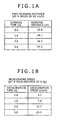
- FIGS. 1A and 1B show a running distance and a decelerated speed, respectively, calculated by
- the host vehicle when the host vehicle is driven at a speed of 65 kilometers per hour, the host vehicle runs 36.1 meters for two seconds as shown in FIG. 1A . Further, for two seconds, the speed of the host vehicle can be reduced by 15.7 kilometers per hour at a deceleration of 0.8 g. Since it is known that a death rate is reduced when the speed at crash is reduced to 50 kilometers per hour or below, the pre-crash speed needs to be reduced as low as possible. In other words, when the time required for crash judgment is reduced in seconds, a great effect is obtained.
- EP 1302747 A1 discloses a system for controlling an object detection system of a land-based vehicle, having at least one detection device with a limited geometrical operating area.
- This system comprises a computing device using information regarding the current or upcoming road situation from an on-board map database as input for computing an attention plan for optimizing the use of the at least one detection device in the object detection system.
- DE 1025816 A1 discloses a method for controlling a cruise control device.
- An object of the present invention is to provide a cruise control device and an obstacle detection device for achieving a safe and appropriate tracking control by reducing a sudden recognition of a short following distance when a preceding vehicle is found in an uphill or downhill gradient, in a curve, or at an intersection, or by reducing the damage of a crash when the crash cannot be avoided.
- obstacle detection information from a sensor that detects obstacles and terrain information of the position of the host vehicle from a map database are input; and if a process of determining the presence of an obstacle is performed when a given condition is satisfied after the sensor detects the obstacle, 1 a condition to determine the presence of the obstacle is changed based on the terrain information of the position of the host vehicle.
- a preceding vehicle exists at a position in a downhill gradient beyond an uphill gradient, a preceding vehicle exists at a position in an uphill gradient beyond a downhill gradient, and a preceding vehicle exists at a position beyond a curve or an intersection, so that a sudden recognition of a short following distance is reduced or the crash reduction braking device can be activated early, thereby performing more appropriate cruise control.
- Embodiments to be described below relate to an adaptive cruise control device, a crash reduction braking device, and a sensor used therein, and shows reduction in judging time required to determine a preceding vehicle by using a navigation device, when the preceding vehicle is detected in a gradient, in a curve, or at an intersection.
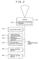
- a cruise control device includes a sensor 201 that detects a following distance and a relative speed, a navigation device 202 that obtains terrain information of the position of the host vehicle and terrain information of the position of a preceding vehicle which is a following distance ahead of the host vehicle, on a map, an inter-vehicle control device 203 that performs constant speed control, following distance control, and pre-crash deceleration control, a brake control device 204, an engine control device 205, and a communication cable 206 that is used to exchange necessary data.
- the engine control device 205 performs transmission control.
- the sensor 201 includes an obstacle detection section 207 that performs an input process and a recognition process in the sensor 201.
- the inter-vehicle control device 203 is realized mainly by software processing and includes an obstacle determination section 208 and an inter-vehicle control section 209.
- the obstacle determination section 208 may be included in the inter-vehicle control device 203 as in this example, or may be included in the sensor 201.
- a function of the inter-vehicle control device 203 may be included in the sensor 201, the navigation device 202, or another control unit.
- an obstacle recognition device includes the sensor 201 that detects a following distance and a relative speed, the navigation device 202 that serves as a map database to obtain terrain information of the position of the host vehicle and terrain information of the position of a preceding vehicle which is a following distance ahead of the host vehicle, on a map, and the communication cable 206 that is used to exchange necessary data.
- the sensor 201 includes the obstacle detection section 207 that performs an input process and a recognition process in the sensor 201, and the obstacle determination section 208 that determines the presence of an obstacle and sends a result to the inter-vehicle control device 203.
- FIG. 2 shows the cruise control device according to the embodiment of the present invention, which includes the sensor 201 that detects the following distance and relative speed to a preceding vehicle, the navigation device 202 that obtains terrain information of the positions of the preceding vehicle and the host vehicle, the inter-vehicle control device 203 that controls the following distance, the brake control device 204 that controls a brake, the engine control device 205 that controls an engine, and the communication cable 206 that connects the above-mentioned devices.
- the engine control device 205 also performs transmission control.
- a controller area network (CAN) is used for communications performed between the above-mentioned devices via the communication cable 206.
- Information necessary for cruise control such as the speed of the host vehicle, can be obtained constantly through the CAN.
- the sensor 201 includes the obstacle detection section 207 that performs an input process in the sensor 201.
- the sensor 201 sends an obstacle recognition and determination result to the inter-vehicle control device 203 via the CAN.
- a dedicated communication cable may be used to exchange data between the navigation device 202 and the sensor 201.
- data may be exchanged by radio.
- input sections that receive information from the sensor 201 and from the navigation device 202 need to be provided for the inter-vehicle control device 203.
- the input sections correspond to connectors connecting the cable.
- the input sections correspond to antennas.
- An input section that receives information from the navigation device 202 is called a terrain information input section
- an input section that receives information from the sensor 201 is called a sensor information input section.
- Control processing of the obstacle determination section 208 of this embodiment is realized by software processing, and the software is stored in the sensor 201 or the navigation device 202.
- FIGS. 4A to 4D illustrate a case where the host vehicle passes through the vicinity of the top of a gradient and suddenly finds a preceding vehicle.
- a hatched vehicle corresponds to the host vehicle and an outlined vehicle corresponds to another vehicle or the preceding vehicle (the same applies to the drawings to be referred to below)
- the preceding vehicle has not been found.
- the driver of the host vehicle visually finds the preceding vehicle.
- the sensor of the host vehicle starts to detect the preceding vehicle.
- the sensor of the host vehicle determines the presence of the preceding vehicle.
- the inter-vehicle control device makes a judgment about determination of the presence of the preceding vehicle after a given required determination time elapses, in order to avoid a false recognition.
- the driver needs to press on the brake.
- the driver who has already found the preceding vehicle, expects that the inter-vehicle control device is activated to perform an automatic deceleration operation, but the deceleration operation is not performed, disappointing the driver for a moment.
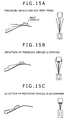
- FIGS. 15A to 15C illustrate an example of detection in a gradient using a laser radar.
- S1801 laser beams are emitted forward and reflected and returned laser beams are received.
- S1802 relative distances are obtained from the time delay of the received laser beams, and directions are obtained from the scan angles.
- objects are grouped according to the relative distances after scanning is finished, to obtain a candidate object from which a predetermined number of beams or more are received.
- S1804 based on the speed of the host vehicle and the relative speed, which corresponds to the difference between the current relative distance to the candidate object and the preceding relative distance thereto, a static object of which the relative speed is close to the speed of the host vehicle is excluded. It is checked whether the candidate object continuously exists for several hundreds of milliseconds.
- S1805 the relative distance to the object, the relative speed thereto, and the number of beams received from the object are output.
- FIG. 5 illustrates a case where the host vehicle passes through the vicinity of the bottom of a gradient and suddenly finds a preceding vehicle.
- the sensor of the host vehicle determines the presence of the preceding vehicle when the host vehicle comes rather close to the preceding vehicle.
- FIG. 6 illustrates a case where the host vehicle passes through the vicinity of a curve and suddenly finds a preceding vehicle. If the preceding vehicle is suddenly recognized beyond the curve, the sensor requires time to determine the presence of the preceding vehicle also in this case.
- FIGS. 16A to 16E illustrate an example of detection in a right-hand curve using the laser radar.
- the preceding vehicle is sequentially detected in order of the right part on the rear of the preceding vehicle, the right and center parts thereon, and the right, center, and left parts thereon.
- the preceding vehicle determination process is started when the three points at the right, center, and left parts on the rear of the preceding vehicle are detected. After the required determination time elapses, the preceding vehicle is determined.
- FIG. 7 illustrates a case where a preceding vehicle is suddenly found beyond an intersection.
- the sensor requires time to determine the presence of the preceding vehicle also in this case.
- the laser radar in order to determine the preceding vehicle and to activate an actuator, it is necessary for the laser radar to detect the three points at the right, center, and left parts on the rear of the preceding vehicle and to monitor the detection state during the required determination time.
- FIG. 8 is a process flow from sensor detection to vehicle control.
- the sensor 201 detects obstacles and outputs data of an obstacle candidate.
- an obstacle determination process is performed.
- the obstacle is determined based on duration in which the obstacle is being detected.
- Information of the obstacle, determined through the obstacle determination process is output.
- the inter-vehicle control device 203 outputs control command values to control the vehicle, such as a torque value, a brake oil pressure value, and a transmission command value.
- the inter-vehicle control device 203 activates an actuator to control the vehicle.
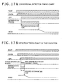
- FIGS. 9A and 9B show timing charts of preceding vehicle detection.
- FIG. 9A shows a conventional detection process.
- FIG. 9B shows a detection process according to this embodiment.
- the senor outputs information on a plurality of obstacles
- the inter-vehicle control section performs a preceding vehicle determination process based on the sensor information, and performs actual vehicle control based on the determination result.
- the state of the detection process shifts to "determining (3)" when information on the detected object is received from the sensor, and shifts to "preceding vehicle determination (4)" after the object is continuously recognized for the required determination time.
- the inter-vehicle control section actuates the actuator.
- a determination process of this embodiment is intended to reduce the duration of the state of "determining (3)". As a result, information on "preceding vehicle determination (4) can be rapidly sent to the inter-vehicle control section 209.
- the determination process is started, and the preceding vehicle is determined after the required determination time elapses.
- the required determination time is set to about three to five seconds.
- the required determination time can be reduced by using terrain information.
- the required determination time can be reduced to about 0.5 to 1 second.
- the free running distance is 36.1 meters if the host vehicle is driven at a speed of 65 kilometers per hour, so that automatic deceleration can be started 36.1 meters short of the location where automatic deceleration is conventionally started.
- a time reduction in seconds is very important for vehicles driven at high speeds.
- the course of a curve can be judged from a steering angle, a yaw rate, and map information of the position of the host vehicle.
- An obstacle may be determined, for example, by reducing the number of points on the obstacle to be detected using laser beams, without waiting for the obstacle to come completely in front of the host vehicle.
- an obstacle may be determined through detection of two points on the obstacle, such as the left and center parts or the right and center parts thereon.
- the preceding vehicle determination process can be similarly performed.
- the stereo camera obtains the parallax between a right image and a left image to obtain the distance to a corresponding point from the parallax.
- FIG. 19 shows the principle of the stereo camera. The distance to an object and a lateral location of the object can be measured.
- FIG. 20 shows an outline of a recognition process using the stereo camera.
- a stereo matching process is performed to obtain points where a right image matches a left image based on the right and left grayscale images.
- a range image calculation process is performed to obtain the distance to each image point from the parallax of the points.
- a grouping process is performed according to the distance. Through the grouping process, the size and the lateral location of an object are recognized.
- a selection process is performed to exclude a static object based on the relative speeds of grouped objects, or to exclude an object outside an area specified by a white road line if a white road line recognition function is provided. Further, an object which does not continuously exist for several hundreds of milliseconds is excluded.
- the relative distance, the relative speed, the lateral location, the width, and the height of an object are output.
- the object is continuously recognized and, when the required determination time elapses, the object is determined to be a preceding vehicle.
- the object may be determined to be a preceding vehicle. Further, when it is judged that the host vehicle is traveling in a gradient, a criterion of height for an object is made smaller and, after the object is recognized for the required determination time, the object may be determined to be a preceding vehicle.
- the preceding vehicle determination time can be reduced by using terrain information.
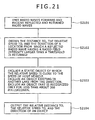
- FIG. 21 shows an example of a recognition process using the millimeter wave radar.
- S2101 radio waves are emitted forward and reflected and returned radio waves are received.
- S2102 the distance to, the relative speed to, and the direction of a location from which a reflected radio wave having a radio field intensity larger than a threshold is returned are obtained. It is possible to obtain the distance from the delay of a received radio wave, the relative speed from the Doppler frequency, and the direction from the scan angle.
- the object is continuously recognized, and, when the required determination time elapses, the object is determined to be a preceding vehicle. Even if the object does not exist in front of the host vehicle, when it is recognized, by using information indicating that the vehicle is traveling in a curve, that the object exists in the curve for the required determination time, the object can be determined to be a preceding vehicle.
- the required preceding vehicle determination time can be reduced by using terrain information.
- FIG. 22 collectively shows example determination conditions used for respective sensors.
- FIG. 10 shows data exchange between the obstacle determination process and the navigation device 202. Details of the obstacle determination process will be described below.
- the obstacle determination process sends information on the following distance, to the navigation device 202, and receives, from the navigation device 202, information on the gradients of the positions of the host vehicle and the preceding vehicle and information on the traveling directions of the host vehicle and the preceding vehicle.
- FIG. 11 shows a flowchart of the obstacle determination process. Details of a method of implementing the obstacle determination process will be described.
- the obstacle determination process is usually called to be executed at intervals of 10 milliseconds, for example.
- S1101 data is obtained from the sensor and checked. When a new obstacle is detected, a predetermined timer and a predetermined timer value are assigned. When an obstacle which was detected before is detected again, its timer value is decremented. Further, when an obstacle has disappeared or has shifted from the front of the host vehicle, the corresponding timer is eliminated.
- MIN minimum required determination time
- the terrain condition search process of S1105 and the judgment process of S1106 are added, so that there is no need to always wait for the required determination time to elapse and, when the terrain condition is established, the obstacle is determined immediately.
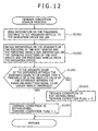
- FIG. 12 is a flowchart of the terrain condition search process.
- S1201 information on the following distance to the preceding vehicle is sent to the navigation device 202 via the CAN.
- S1202 information on the gradients of the positions of the host vehicle and the preceding vehicle and information on the traveling directions of the host vehicle and the preceding vehicle are obtained from the navigation device 202.
- the terrain condition is established (Yes) in the judgment of S1203, and the process flow advances to S1204 to perform a terrain condition flag setting process.
- the process flow advances to S1205 to perform a terrain condition flag clear process.
- FIGS. 13A and 13B illustrate how to obtain the gradient differences and the traveling-direction differences. As shown in FIG. 13A , each gradient difference is obtained from the difference between the gradients of the positions of the host vehicle and the preceding vehicle.
- FIG. 13B shows how to obtain the traveling-direction difference in a curve and in an intersection.
- the traveling direction of the host vehicle is obtained from map information of the position of the host vehicle or gyro information of the navigation device 202.
- the traveling direction of the preceding vehicle is obtained from map information of the position of the preceding vehicle. Therefore, the traveling-direction difference is obtained from the difference between the traveling direction of the host vehicle and the traveling direction of the preceding vehicle.
- the traveling-direction difference can be obtained from the traveling direction of the preceding vehicle and the traveling direction of the host vehicle, obtained using a gyro or the like.
- FIG. 14 shows a process performed in the navigation device 202.
- S1401 information on the following distance is obtained via the CAN.
- S1402 the gradients of and the traveling directions (traveling directions of north, south, east, and west) at the positions of the host vehicle and the preceding vehicle, which is the following distance ahead of the host vehicle, are obtained.
- S1403 information on the obtained gradients and traveling directions are sent via the CAN.
- the obstacle determination process has been described in detail with reference to FIGS. 11 to 14 .
- the required determination time for an obstacle can be reduced by using the terrain condition concerning a gradient or a curve obtained in the navigation device 202.
- the obstacle determination process sends information on the following distance to the navigation device 202, obtains information on the gradients and the traveling directions from the navigation device 202, and sets the terrain condition flags.
- data exchange between the obstacle determination process and the navigation device 202 can be implemented not only by the way shown in FIG. 10 but also by two example ways to be described below.
- FIG. 23 shows another data exchange (2) between the obstacle determination process and the navigation device 202.
- the obstacle determination process inquires a terrain condition of the navigation device 202, and obtains the terrain condition from the navigation device 202.
- the navigation device 202 has an electronic map with terrain conditions.
- An obstacle determination process is the same as that shown in FIG. 11 , so a description thereof is omitted.
- FIG. 24 shows another terrain condition search process (2).
- the obstacle determination section 208 inquires a terrain condition of the navigation device 202 via the CAN.
- a terrain condition flag is received from the navigation device 202.
- FIG. 25 shows another process (2) performed in the navigation device 202.
- an inquiry is received from the obstacle determination section 208 via the CAN.
- terrain information associated with the position of the host vehicle is obtained from the map.
- the setting of the terrain condition flag is sent to the obstacle determination section 208.
- FIG. 26 shows a method of generating a map having terrain conditions.
- information on the gradient and the traveling direction at each location on a road map are specified such that the information can be retrieved.
- the gradient difference and the traveling-direction difference between a predetermined location (1) and a location (2) which is a sensor-detection distance away from the predetermined location (1) are obtained.
- the terrain condition flag of the predetermined location (1) is set on in S2603.
- the predetermined location (1) is associated with the terrain condition flag on map data.
- such map data is generated for the entire map by specifying locations at intervals of five meters, for example, to set the terrain condition flags there.
- the required determination time (MIN) may be set slightly longer.
- a special map is used such that the terrain condition flag can be set in the navigation device 202.
- the obstacle determination section 208 obtains a terrain information table for traveling directions, from the navigation device 202 in advance, and the terrain condition flags are set according to information of the terrain information table.
- FIG. 27 shows still another data exchange (3) between the obstacle determination process and the navigation device 202.
- the navigation device 202 sends the terrain information table to the obstacle determination section 208 through still another process (3) performed in the navigation device 202.
- the terrain information table includes each distance, and the gradient and traveling direction at the location specified by the distance.
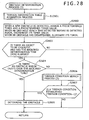
- FIG. 28 shows still another obstacle determination process (3).
- the obstacle determination process (3) of FIG. 28 is different from the obstacle determination process of FIG. 11 in that a terrain information table acquisition process in S2801 is added and still another terrain condition search process (3) in S2806 is used.
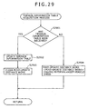
- FIG. 29 shows the terrain information table acquisition process.
- S2901 it is judged whether the terrain information table has been received from the navigation device 202.
- the terrain information table is updated in S2902 and a post-update distance work for obtaining a running distance after the terrain information table is updated is cleared in S2903.
- the judgment in S2901 is No, the value of the post-update distance work is updated based on the speed of the host vehicle and the calling interval of the terrain information table acquisition process, in S2904.
- FIG. 30 shows still another terrain condition search process (3).
- S3001 it is judged whether the terrain information table has been updated.
- the process flow advances to S33002.
- the judgment in S3001 is No, which means that the terrain information table has not been updated or is not used, so the terrain condition flag is cleared in S3006 and the process flow returns.
- the terrain information table (the distance, the gradient, and the traveling direction) and the post-update distance work are referred to.
- terrain information (the gradient and the traveling direction) of the location specified by a distance corresponding to the post-update distance is obtained. If the post-update distance falls within the range of two distances specified in the terrain information table, the gradient and the traveling direction are obtained through interpolation calculation. In S3004, terrain information (the gradient and the traveling direction) of the location specified by a distance corresponding to "the post-update distance plus the following distance” is obtained. If the distance falls within the range of two distances specified in the terrain information table, the gradient and the traveling direction are obtained through interpolation calculation.
- the gradient difference is obtained from the above-mentioned two gradients and the traveling-direction difference is obtained from the above-mentioned two traveling directions.
- the terrain condition flag is set.
- FIG. 31 shows the process (3) performed in the navigation device 202.
- the terrain information table for the traveling road (a traveling distance from the current location, and the gradient and traveling direction at the location specified by the traveling distance) is periodically obtained.
- the terrain information table is sent to the obstacle determination section 208 via the CAN.
- the obstacle determination section 208 obtains the terrain information table for the traveling directions, from the navigation device 202 in advance, and the terrain condition flags are set according to information of the terrain information table.
- Each of the determination conditions shown in FIG. 22 can be specified in the obstacle determination section 208 through the navigation device 202 or another input means. Specifically, a minimum required determination time, a required determination time, a detection method used in a curve, and a detection method used in a gradient can be specified.
- ACC control is realized by the process of the inter-vehicle control section 209.
- constant-speed control is performed when there is no preceding vehicle
- tracking control feedback control of the following distance and the relative speed
- the inter-vehicle control section 209 can perform pre-crash damage reduction control at the same time.
- the pre-crash damage reduction control is used to perform brake control when a crash cannot be avoided and is activated when the time to collision with a preceding vehicle is 0.8 seconds or below.
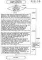
- the inter-vehicle control section 209 can perform alarming, preliminary deceleration, and deceleration as shown in FIG. 32 . Specifically, the inter-vehicle control section 209 can obtain the time to collision (TTC) with the preceding vehicle, judges the value of the TTC, and perform the alarming, the preliminary deceleration, and the deceleration. Further, the inter-vehicle control section 209 can change the deceleration applied by the brake depending on the value of the TTC.
- TTC time to collision
- the TTC can be obtained by a formula 4 or by a formula 5 in which acceleration is taken into account.
- the obstacle determination time is reduced by the terrain condition, so that the activation operation of the inter-vehicle control section 209 can be performed earlier.to avoid a sudden recognition of a short following distance.
- the first embodiment can be implemented as described above.
- the effect can be recognized in driving at a gradient or at a curve.
- a vehicle is driven in the same manner while a part of the function of the navigation device 202 is limited, for example, by blocking a GPS antenna, a difference in effect can be recognized and implementation of the present invention can be checked.
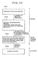
- FIG. 3 shows an obstacle recognition device according to a second embodiment of the present invention, which includes the sensor 201 that obtains the following distance and relative speed to a preceding vehicle, the navigation device 202 that obtains terrain information of the positions of the host vehicle and the preceding vehicle, and the communication cable 206 that connects the above-mentioned devices.
- the CAN is used for communications performed between the above-mentioned devices via the communication cable 206.
- the sensor 201 includes the obstacle detection section 207 that performs an input process in the sensor 201, and the obstacle determination section 208 that determines recognition of an obstacle.
- the sensor 201 sends an obstacle recognition and determination result to the inter-vehicle control device 203 via the CAN.
- a dedicated communication cable may be used to exchange data between the navigation device 202 and the sensor 201.
- Control processing according to this embodiment is realized by software processing, and the software is stored in the sensor 201 or the navigation device 202.
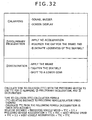
- FIG. 33 is another process flow (2) from sensor detection to vehicle control.
- the process flow (2) of FIG. 33 is different from the process flow of FIG. 8 in that the obstacle determination process is implemented by the sensor 201 instead of the inter-vehicle control device 203.
- the required determination time for an obstacle can be reduced by using the terrain condition concerning a gradient or a curve, obtained in the navigation device 202, so that information about the obstacle can be rapidly sent to the inter-vehicle control device 203.
- the required determination time can be set or changed due to terrain, by instructions.
- the obstacle recognition device can output, in addition to conventional information about a number of obstacle candidates, determined-obstacle information obtained by using the terrain condition, which is a feature of this embodiment.
- the obstacle recognition device can be implemented by using a laser radar, a stereo camera, or a millimeter wave radar. Since details of their processing are the same as those described in the first embodiment, descriptions thereof are omitted.
- the obstacle recognition device not only the laser radar, the stereo camera, and the millimeter wave radar but also any sensor which can obtain the relative distance and relative speed to a preceding vehicle can be used. Further, it is also possible to use a sensor of which the detection angle can be changed (vertically and horizontally) by using information on the gradient of the position of the host vehicle and information on a steering angle, by a known technique.
- the second embodiment can be implemented as described above.
Landscapes
- Engineering & Computer Science (AREA)
- Physics & Mathematics (AREA)
- General Physics & Mathematics (AREA)
- Automation & Control Theory (AREA)
- Transportation (AREA)
- Mechanical Engineering (AREA)
- Traffic Control Systems (AREA)
- Navigation (AREA)
- Radar Systems Or Details Thereof (AREA)
- Control Of Driving Devices And Active Controlling Of Vehicle (AREA)
Abstract
Description
- The present invention relates to a vehicle control device and a vehicle control method. In particular, the present invention is preferably applied to vehicles provided with means for detecting obstacles, a vehicle in front (a preceding vehicle), and the like.
- An adaptive cruise control device (hereinafter, referred to as ACC device) realizes a function in which a driver can specify a target speed and a target distance to the preceding vehicle (a target following distance) through an input and output display unit, and a function of, when there is no preceding vehicle, controlling the actual speed so as to mach the target speed and of, when there is a preceding vehicle, following the preceding vehicle while maintaining the target following distance. The ACC device is conventionally intended to be used in express highways, but is now increasingly used in general roads which have more curves and undulations. However, in a case where a preceding vehicle or a stationary object exists beyond an uphill gradient but cannot be seen, when the host vehicle reaches at the top of the gradient, the preceding vehicle or the stationary object suddenly comes into sight. Accordingly, it is difficult for the ACC device to rapidly reduce the speed, giving a feeling of danger in some cases. The ACC device usually requires several seconds to recognize a preceding vehicle. The presence of the preceding vehicle is continuously checked for the several seconds to judge whether the preceding vehicle is finally determined. Control commands are issued to an alarming device and actuators (such as an accelerator, a transmission, and a brake), based on the determination result. Therefore, through a usual preceding vehicle determination process, timing to start deceleration is delayed because the presence of the preceding vehicle needs to be checked for several seconds. Further, when the host vehicle is driven from a downhill gradient to an uphill gradient and finds a preceding vehicle located in the uphill gradient, timing to start deceleration is also delayed because the sensor uses a required determination time to check the presence of the preceding vehicle although the preceding vehicle has been visually found.
- In short, with current ACC devices and crash reduction braking devices, braking tends to be used later than when the driver brakes the host vehicle after visual recognition. Since the preceding vehicle has come into sight of the driver, it is necessary for the driver to rapidly start deceleration.
- Since a pre-crash speed is a key in cruise control systems, especially, in crash reduction braking devices, reduction in detection time is important.
FIGS. 1A and 1B show a running distance and a decelerated speed, respectively, calculated by - the following
formulae 1 and 2:

- For example, when the host vehicle is driven at a speed of 65 kilometers per hour, the host vehicle runs 36.1 meters for two seconds as shown in
FIG. 1A . Further, for two seconds, the speed of the host vehicle can be reduced by 15.7 kilometers per hour at a deceleration of 0.8 g. Since it is known that a death rate is reduced when the speed at crash is reduced to 50 kilometers per hour or below, the pre-crash speed needs to be reduced as low as possible. In other words, when the time required for crash judgment is reduced in seconds, a great effect is obtained. - Further, there is a known technique of using a navigation device to judge structures such as an ETC gate and a railroad crossing at an early stage and to find a preceding vehicle at an early stage according to the degree of road congestion (for example, see
JP-A-2003-141698 - However, it is difficult to find a preceding vehicle in a gradient or in a curve at an early stage, and there is no invention of achieving prompt recognition of a preceding vehicle in a gradient or in a curve.
- On the other hand, maps have been more precise in navigation devices, and it is known that terrain information is included in the navigation devices.
-
EP 1302747 A1 discloses a system for controlling an object detection system of a land-based vehicle, having at least one detection device with a limited geometrical operating area. This system comprises a computing device using information regarding the current or upcoming road situation from an on-board map database as input for computing an attention plan for optimizing the use of the at least one detection device in the object detection system. -
DE 1025816 A1 discloses a method for controlling a cruise control device. - An object of the present invention is to provide a cruise control device and an obstacle detection device for achieving a safe and appropriate tracking control by reducing a sudden recognition of a short following distance when a preceding vehicle is found in an uphill or downhill gradient, in a curve, or at an intersection, or by reducing the damage of a crash when the crash cannot be avoided.
- The invention is defined in the independent claims.
- Therefore, obstacle detection information from a sensor that detects obstacles and terrain information of the position of the host vehicle from a map database are input; and if a process of determining the presence of an obstacle is performed when a given condition is satisfied after the sensor detects the obstacle, 1 a condition to determine the presence of the obstacle is changed based on the terrain information of the position of the host vehicle.
- Accordingly, it is possible to find early that a preceding vehicle exists at a position in a downhill gradient beyond an uphill gradient, a preceding vehicle exists at a position in an uphill gradient beyond a downhill gradient, and a preceding vehicle exists at a position beyond a curve or an intersection, so that a sudden recognition of a short following distance is reduced or the crash reduction braking device can be activated early, thereby performing more appropriate cruise control.
-
-
FIG. 1A shows a running distance with respect to time andFIG. 1B shows a decelerated speed with respect to time, according to an embodiment of the present invention. -
FIG. 2 is a block diagram of this embodiment. -
FIG. 3 is another block diagram (2) of this embodiment. -
FIGS. 4A to 4D illustrate a case where the host vehicle passes through the vicinity of the top of a gradient and suddenly finds a preceding vehicle. -
FIG. 5 illustrates a case where the host vehicle passes through the vicinity of the bottom of a gradient and suddenly finds a preceding vehicle. -
FIG. 6 illustrates a case where the host vehicle passes through the vicinity of a curve and suddenly finds a preceding vehicle. -
FIG. 7 illustrates a case where the host vehicle suddenly finds a preceding vehicle beyond an intersection. -
FIG. 8 is a process flow from sensor detection to vehicle control. -
FIGS. 9A and 9B are timing charts of preceding vehicle detection. -
FIG. 10 shows data exchange between an obstacle determination process and a navigation device. -
FIG. 11 shows the obstacle determination process. -
FIG. 12 shows a terrain condition search process. -
FIGS. 13A and 13B illustrate how to obtain gradient differences and traveling-direction differences. -
FIG. 14 shows a process performed in the navigation device. -
FIGS. 15A to 15C illustrate an example of detection (in a gradient) using a laser radar. -
FIGS. 16A to 16E illustrate an example of detection (in a curve) using the laser radar. -
FIGS. 17A to 17B are example timing charts of detection using the laser radar. -
FIG. 18 shows an example of a recognition process using the laser radar. -
FIG. 19 shows the principle of a stereo camera. -
FIG. 20 shows an example of a recognition process using the stereo camera. -
FIG. 21 shows an example of a recognition process using a millimeter wave radar. -
FIG. 22 shows example determination conditions used for respective sensors. -
FIG. 23 shows another data exchange (2) between the obstacle determination process and the navigation device. -
FIG. 24 shows another terrain condition search process (2). -
FIG. 25 shows another process (2) performed in the navigation device. -
FIG. 26 shows a method of generating a map having terrain conditions. -
FIG. 27 shows still another data exchange (3) between the obstacle determination process and the navigation device. -
FIG. 28 shows still another obstacle determination process (3). -
FIG. 29 shows a terrain information table acquisition process. -
FIG. 30 shows still another terrain condition search process (3). -
FIG. 31 shows still another process (3) performed in the navigation device. -
FIG. 32 shows variations of alarming and braking. -
FIG. 33 is another process flow (2) from sensor detection to vehicle control. - Embodiments to be described below relate to an adaptive cruise control device, a crash reduction braking device, and a sensor used therein, and shows reduction in judging time required to determine a preceding vehicle by using a navigation device, when the preceding vehicle is detected in a gradient, in a curve, or at an intersection.
- As shown in a block diagram of
FIG. 2 , a cruise control device according to an embodiment of the present invention includes asensor 201 that detects a following distance and a relative speed, anavigation device 202 that obtains terrain information of the position of the host vehicle and terrain information of the position of a preceding vehicle which is a following distance ahead of the host vehicle, on a map, aninter-vehicle control device 203 that performs constant speed control, following distance control, and pre-crash deceleration control, abrake control device 204, anengine control device 205, and acommunication cable 206 that is used to exchange necessary data. Theengine control device 205 performs transmission control. Thesensor 201 includes anobstacle detection section 207 that performs an input process and a recognition process in thesensor 201. - The
inter-vehicle control device 203 is realized mainly by software processing and includes anobstacle determination section 208 and aninter-vehicle control section 209. Theobstacle determination section 208 may be included in theinter-vehicle control device 203 as in this example, or may be included in thesensor 201. A function of theinter-vehicle control device 203 may be included in thesensor 201, thenavigation device 202, or another control unit. - As shown in a block diagram of
FIG. 3 , an obstacle recognition device according to a first embodiment of the present invention includes thesensor 201 that detects a following distance and a relative speed, thenavigation device 202 that serves as a map database to obtain terrain information of the position of the host vehicle and terrain information of the position of a preceding vehicle which is a following distance ahead of the host vehicle, on a map, and thecommunication cable 206 that is used to exchange necessary data. Thesensor 201 includes theobstacle detection section 207 that performs an input process and a recognition process in thesensor 201, and theobstacle determination section 208 that determines the presence of an obstacle and sends a result to theinter-vehicle control device 203. -
FIG. 2 shows the cruise control device according to the embodiment of the present invention, which includes thesensor 201 that detects the following distance and relative speed to a preceding vehicle, thenavigation device 202 that obtains terrain information of the positions of the preceding vehicle and the host vehicle, theinter-vehicle control device 203 that controls the following distance, thebrake control device 204 that controls a brake, theengine control device 205 that controls an engine, and thecommunication cable 206 that connects the above-mentioned devices. Theengine control device 205 also performs transmission control. A controller area network (CAN) is used for communications performed between the above-mentioned devices via thecommunication cable 206. Information necessary for cruise control, such as the speed of the host vehicle, can be obtained constantly through the CAN. Thesensor 201 includes theobstacle detection section 207 that performs an input process in thesensor 201. Thesensor 201 sends an obstacle recognition and determination result to theinter-vehicle control device 203 via the CAN. - Instead of the CAN, a dedicated communication cable may be used to exchange data between the
navigation device 202 and thesensor 201. Alternatively, data may be exchanged by radio. In either case, input sections that receive information from thesensor 201 and from thenavigation device 202 need to be provided for theinter-vehicle control device 203. In a case of using the CAN or the dedicated communication cable, the input sections correspond to connectors connecting the cable. In a case of using radio, the input sections correspond to antennas. An input section that receives information from thenavigation device 202 is called a terrain information input section, and an input section that receives information from thesensor 201 is called a sensor information input section. - Control processing of the
obstacle determination section 208 of this embodiment is realized by software processing, and the software is stored in thesensor 201 or thenavigation device 202. - Hereinafter, a conventional detection method and a conventional preceding vehicle determination process will be described.
-
FIGS. 4A to 4D illustrate a case where the host vehicle passes through the vicinity of the top of a gradient and suddenly finds a preceding vehicle. InFIGS. 4A to 4B , a hatched vehicle corresponds to the host vehicle and an outlined vehicle corresponds to another vehicle or the preceding vehicle (the same applies to the drawings to be referred to below) InFIG. 4A , the preceding vehicle has not been found. InFIG. 4B , the driver of the host vehicle visually finds the preceding vehicle. InFIG. 4C , the sensor of the host vehicle starts to detect the preceding vehicle. InFIG. 4D , the sensor of the host vehicle determines the presence of the preceding vehicle. - Soon after the driver of the host vehicle visually finds the preceding vehicle, the sensor of the host vehicle starts to detect the preceding vehicle. The inter-vehicle control device makes a judgment about determination of the presence of the preceding vehicle after a given required determination time elapses, in order to avoid a false recognition. However, in the case shown in
FIGS. 4A to 4D , since the presence of the preceding vehicle is determined when the host vehicle comes rather close to the preceding vehicle, the driver needs to press on the brake. The driver, who has already found the preceding vehicle, expects that the inter-vehicle control device is activated to perform an automatic deceleration operation, but the deceleration operation is not performed, disappointing the driver for a moment. -
FIGS. 15A to 15C illustrate an example of detection in a gradient using a laser radar. - When a preceding vehicle suddenly appears in a lower part of the gradient as shown in
FIG. 15B , three points at the center, right, and left parts on the rear of the preceding vehicle are detected by the laser radar to start a preceding vehicle determination process. After a required determination time elapses, the detection of the preceding vehicle is determined. - An outline of a recognition process using the laser radar will be described with reference to
FIG. 18 . In S1801, laser beams are emitted forward and reflected and returned laser beams are received. In S1802, relative distances are obtained from the time delay of the received laser beams, and directions are obtained from the scan angles. In S1803, objects are grouped according to the relative distances after scanning is finished, to obtain a candidate object from which a predetermined number of beams or more are received. In S1804, based on the speed of the host vehicle and the relative speed, which corresponds to the difference between the current relative distance to the candidate object and the preceding relative distance thereto, a static object of which the relative speed is close to the speed of the host vehicle is excluded. It is checked whether the candidate object continuously exists for several hundreds of milliseconds. In S1805, the relative distance to the object, the relative speed thereto, and the number of beams received from the object are output. -
FIG. 5 illustrates a case where the host vehicle passes through the vicinity of the bottom of a gradient and suddenly finds a preceding vehicle. As in the case where the host vehicle passes through the vicinity of the top of a gradient, the sensor of the host vehicle determines the presence of the preceding vehicle when the host vehicle comes rather close to the preceding vehicle. -
FIG. 6 illustrates a case where the host vehicle passes through the vicinity of a curve and suddenly finds a preceding vehicle. If the preceding vehicle is suddenly recognized beyond the curve, the sensor requires time to determine the presence of the preceding vehicle also in this case. -
FIGS. 16A to 16E illustrate an example of detection in a right-hand curve using the laser radar. When a preceding vehicle is found in the right-hand curve, the preceding vehicle is sequentially detected in order of the right part on the rear of the preceding vehicle, the right and center parts thereon, and the right, center, and left parts thereon. The preceding vehicle determination process is started when the three points at the right, center, and left parts on the rear of the preceding vehicle are detected. After the required determination time elapses, the preceding vehicle is determined. -
FIG. 7 illustrates a case where a preceding vehicle is suddenly found beyond an intersection. When the host vehicle changes its direction and finds the preceding vehicle, the sensor requires time to determine the presence of the preceding vehicle also in this case. - As described above with reference to
FIGS. 4A to 4D andFIGS. 5 to 7 , in order to determine the preceding vehicle and to activate an actuator, it is necessary for the laser radar to detect the three points at the right, center, and left parts on the rear of the preceding vehicle and to monitor the detection state during the required determination time. - Next, a method of reducing the required determination time, according to this embodiment will be described with reference to
FIG. 8 and subsequent drawings. -
FIG. 8 is a process flow from sensor detection to vehicle control. - In S801, the
sensor 201 detects obstacles and outputs data of an obstacle candidate. In S802, an obstacle determination process is performed. In the obstacle determination process, the obstacle is determined based on duration in which the obstacle is being detected. Information of the obstacle, determined through the obstacle determination process, is output. In S803, based on the host vehicle speed and the distance and relative speed to the determined obstacle, theinter-vehicle control device 203 outputs control command values to control the vehicle, such as a torque value, a brake oil pressure value, and a transmission command value. In S804, theinter-vehicle control device 203 activates an actuator to control the vehicle. -
FIGS. 9A and 9B show timing charts of preceding vehicle detection.FIG. 9A shows a conventional detection process.FIG. 9B shows a detection process according to this embodiment. - In general, the sensor outputs information on a plurality of obstacles, and the inter-vehicle control section performs a preceding vehicle determination process based on the sensor information, and performs actual vehicle control based on the determination result.
- In a sensor output process, when an object satisfying a condition is detected, the state of the detection process usually shifts from "detecting (1)" to "detecting (an object satisfying a condition is detected) (2)" in which a result is output.
- In a conventional determination process, the state of the detection process shifts to "determining (3)" when information on the detected object is received from the sensor, and shifts to "preceding vehicle determination (4)" after the object is continuously recognized for the required determination time.
- When the state of the detection process shifts to "preceding vehicle determination (4)", the inter-vehicle control section actuates the actuator.
- A determination process of this embodiment is intended to reduce the duration of the state of "determining (3)". As a result, information on "preceding vehicle determination (4) can be rapidly sent to the
inter-vehicle control section 209. - In the case of using the laser radar, as shown in
FIG. 17A , when the three points at the right, center, and left parts on the rear of the preceding vehicle have been detected, the determination process is started, and the preceding vehicle is determined after the required determination time elapses.. With conventional techniques, the required determination time is set to about three to five seconds. - In this embodiment, as shown in
FIG. 17B , the required determination time can be reduced by using terrain information. For example, the required determination time can be reduced to about 0.5 to 1 second. When the required determination time is reduced by about 2 seconds, the free running distance is 36.1 meters if the host vehicle is driven at a speed of 65 kilometers per hour, so that automatic deceleration can be started 36.1 meters short of the location where automatic deceleration is conventionally started. A time reduction in seconds is very important for vehicles driven at high speeds. - The course of a curve can be judged from a steering angle, a yaw rate, and map information of the position of the host vehicle. An obstacle may be determined, for example, by reducing the number of points on the obstacle to be detected using laser beams, without waiting for the obstacle to come completely in front of the host vehicle. For example, in a curve, an obstacle may be determined through detection of two points on the obstacle, such as the left and center parts or the right and center parts thereon.
- Also in a case of using a stereo camera, the preceding vehicle determination process can be similarly performed. The stereo camera obtains the parallax between a right image and a left image to obtain the distance to a corresponding point from the parallax.
FIG. 19 shows the principle of the stereo camera. The distance to an object and a lateral location of the object can be measured. -
FIG. 20 shows an outline of a recognition process using the stereo camera. In S2001, a stereo matching process is performed to obtain points where a right image matches a left image based on the right and left grayscale images. In S2002, a range image calculation process is performed to obtain the distance to each image point from the parallax of the points. In S2003, a grouping process is performed according to the distance. Through the grouping process, the size and the lateral location of an object are recognized. In S2004, a selection process is performed to exclude a static object based on the relative speeds of grouped objects, or to exclude an object outside an area specified by a white road line if a white road line recognition function is provided. Further, an object which does not continuously exist for several hundreds of milliseconds is excluded. In S2005, the relative distance, the relative speed, the lateral location, the width, and the height of an object are output. - The object is continuously recognized and, when the required determination time elapses, the object is determined to be a preceding vehicle.
- Even if the object does not exist in front of the host vehicle, when it is recognized, by using information on a curve, that the obj ect exists in the course of the curve for the required determination time, the object may be determined to be a preceding vehicle. Further, when it is judged that the host vehicle is traveling in a gradient, a criterion of height for an object is made smaller and, after the object is recognized for the required determination time, the object may be determined to be a preceding vehicle.
- In this embodiment, the preceding vehicle determination time can be reduced by using terrain information.
- Also in a case of using a millimeter wave radar, the preceding vehicle determination process can be similarly performed.
FIG. 21 shows an example of a recognition process using the millimeter wave radar. In S2101, radio waves are emitted forward and reflected and returned radio waves are received. In S2102, the distance to, the relative speed to, and the direction of a location from which a reflected radio wave having a radio field intensity larger than a threshold is returned are obtained. It is possible to obtain the distance from the delay of a received radio wave, the relative speed from the Doppler frequency, and the direction from the scan angle. - In S2103, a static object of which the relative speed is close to the speed of host vehicle is excluded. An object existing in another lane is excluded from the obtained direction. An object that is recognized only for less than about 300 milliseconds is excluded. In S2104, the relative distance to, the relative speed to, and the direction of an object are output.
- The object is continuously recognized, and, when the required determination time elapses, the object is determined to be a preceding vehicle. Even if the object does not exist in front of the host vehicle, when it is recognized, by using information indicating that the vehicle is traveling in a curve, that the object exists in the curve for the required determination time, the object can be determined to be a preceding vehicle.
- In this embodiment, the required preceding vehicle determination time can be reduced by using terrain information.
-
FIG. 22 collectively shows example determination conditions used for respective sensors. -
FIG. 10 shows data exchange between the obstacle determination process and thenavigation device 202. Details of the obstacle determination process will be described below. The obstacle determination process sends information on the following distance, to thenavigation device 202, and receives, from thenavigation device 202, information on the gradients of the positions of the host vehicle and the preceding vehicle and information on the traveling directions of the host vehicle and the preceding vehicle. -
FIG. 11 shows a flowchart of the obstacle determination process. Details of a method of implementing the obstacle determination process will be described. The obstacle determination process is usually called to be executed at intervals of 10 milliseconds, for example. In S1101, data is obtained from the sensor and checked. When a new obstacle is detected, a predetermined timer and a predetermined timer value are assigned. When an obstacle which was detected before is detected again, its timer value is decremented. Further, when an obstacle has disappeared or has shifted from the front of the host vehicle, the corresponding timer is eliminated. When there is an obstacle to be checked and a minimum required determination time (MIN) has elapsed, the judgment in S1102 is Yes, the process flow advances to S1103 to make another judgment. When the judgment in S1102 is No, the process flow returns. In S1103, it is judged from the timer value whether there is an obstacle which exists over the required determination time. If the judgment in S1103 is Yes, the process flow advances to S1104 to determine the obstacle. If the judgment in S1103 is No, the process flow advances to S1105 to perform a terrain condition search process (details thereof are shown inFIG. 12 ). After the terrain condition search process of S1105, the process flow advances to S1106 to perform a terrain condition judgment process. If a terrain condition is established (Yes) in S1106, the process flow advances to S1104 to perform the obstacle determination process. If the terrain condition is not established (No) in S1106, the process flow returns. - In this embodiment, the terrain condition search process of S1105 and the judgment process of S1106 are added, so that there is no need to always wait for the required determination time to elapse and, when the terrain condition is established, the obstacle is determined immediately.
-
FIG. 12 is a flowchart of the terrain condition search process. In S1201, information on the following distance to the preceding vehicle is sent to thenavigation device 202 via the CAN. Next, in S1202, information on the gradients of the positions of the host vehicle and the preceding vehicle and information on the traveling directions of the host vehicle and the preceding vehicle are obtained from thenavigation device 202. When the absolute value of the difference between the gradients is equal to or larger than a threshold or when the absolute value of the difference between the traveling directions is equal to or larger than a threshold, the terrain condition is established (Yes) in the judgment of S1203, and the process flow advances to S1204 to perform a terrain condition flag setting process. When the terrain condition is not established (No) in S1203, the process flow advances to S1205 to perform a terrain condition flag clear process. -
FIGS. 13A and 13B illustrate how to obtain the gradient differences and the traveling-direction differences. As shown inFIG. 13A , each gradient difference is obtained from the difference between the gradients of the positions of the host vehicle and the preceding vehicle. -
FIG. 13B shows how to obtain the traveling-direction difference in a curve and in an intersection. The traveling direction of the host vehicle is obtained from map information of the position of the host vehicle or gyro information of thenavigation device 202. The traveling direction of the preceding vehicle is obtained from map information of the position of the preceding vehicle. Therefore, the traveling-direction difference is obtained from the difference between the traveling direction of the host vehicle and the traveling direction of the preceding vehicle. - Instead of the above-mentioned method, another method can be used in which the traveling direction difference is obtained from the radius of curvature of a curve and the following distance. A calculation method is shown in a
formula 3.
- When the preceding vehicle exists beyond an intersection, the traveling-direction difference can be obtained from the traveling direction of the preceding vehicle and the traveling direction of the host vehicle, obtained using a gyro or the like.
-
FIG. 14 shows a process performed in thenavigation device 202. In S1401, information on the following distance is obtained via the CAN. In S1402, the gradients of and the traveling directions (traveling directions of north, south, east, and west) at the positions of the host vehicle and the preceding vehicle, which is the following distance ahead of the host vehicle, are obtained. In S1403, information on the obtained gradients and traveling directions are sent via the CAN. - The obstacle determination process has been described in detail with reference to
FIGS. 11 to 14 . - As described above, the required determination time for an obstacle can be reduced by using the terrain condition concerning a gradient or a curve obtained in the
navigation device 202. - In the data exchange between the obstacle determination process and the
navigation device 202, shown inFIG. 10 , the obstacle determination process sends information on the following distance to thenavigation device 202, obtains information on the gradients and the traveling directions from thenavigation device 202, and sets the terrain condition flags. However, in this embodiment, data exchange between the obstacle determination process and thenavigation device 202 can be implemented not only by the way shown inFIG. 10 but also by two example ways to be described below. - First, an example of setting a terrain condition flag in the
navigation device 202 will be described with reference toFIG. 23 and other figures. -
FIG. 23 shows another data exchange (2) between the obstacle determination process and thenavigation device 202. The obstacle determination process inquires a terrain condition of thenavigation device 202, and obtains the terrain condition from thenavigation device 202. Thenavigation device 202 has an electronic map with terrain conditions. - An obstacle determination process is the same as that shown in
FIG. 11 , so a description thereof is omitted. -
FIG. 24 shows another terrain condition search process (2). In S2401, theobstacle determination section 208 inquires a terrain condition of thenavigation device 202 via the CAN. In S2402, a terrain condition flag is received from thenavigation device 202. -
FIG. 25 shows another process (2) performed in thenavigation device 202. In S2501, an inquiry is received from theobstacle determination section 208 via the CAN. In S2502, based on the position of the host vehicle, terrain information associated with the position of the host vehicle is obtained from the map. In S2503, the setting of the terrain condition flag is sent to theobstacle determination section 208. -
FIG. 26 shows a method of generating a map having terrain conditions. In S2601, information on the gradient and the traveling direction at each location on a road map are specified such that the information can be retrieved. In S2602, the gradient difference and the traveling-direction difference between a predetermined location (1) and a location (2) which is a sensor-detection distance away from the predetermined location (1) are obtained. When one of or both of the gradient difference and the traveling-direction difference are larger than respective thresholds, the terrain condition flag of the predetermined location (1) is set on in S2603. In S2604, the predetermined location (1) is associated with the terrain condition flag on map data. In S2605, such map data is generated for the entire map by specifying locations at intervals of five meters, for example, to set the terrain condition flags there. - Since the locations are specified at intervals of the sensor-detection distance, changes in terrain tend to occur. Therefore, the required determination time (MIN) may be set slightly longer.
- In the data exchange (2) between the obstacle determination process and the
navigation device 202, shown inFIG. 23 , a special map is used such that the terrain condition flag can be set in thenavigation device 202. - Next, with reference to
FIG. 27 and other figures, an example case where theobstacle determination section 208 obtains a terrain information table for traveling directions, from thenavigation device 202 in advance, and the terrain condition flags are set according to information of the terrain information table. -
FIG. 27 shows still another data exchange (3) between the obstacle determination process and thenavigation device 202. Thenavigation device 202 sends the terrain information table to theobstacle determination section 208 through still another process (3) performed in thenavigation device 202. - As shown in a lower part of
FIG. 31 , the terrain information table includes each distance, and the gradient and traveling direction at the location specified by the distance. -
FIG. 28 shows still another obstacle determination process (3). The obstacle determination process (3) ofFIG. 28 is different from the obstacle determination process ofFIG. 11 in that a terrain information table acquisition process in S2801 is added and still another terrain condition search process (3) in S2806 is used. -
FIG. 29 shows the terrain information table acquisition process. In S2901, it is judged whether the terrain information table has been received from thenavigation device 202. When the judgment in S2901 is Yes, the terrain information table is updated in S2902 and a post-update distance work for obtaining a running distance after the terrain information table is updated is cleared in S2903. When the judgment in S2901 is No, the value of the post-update distance work is updated based on the speed of the host vehicle and the calling interval of the terrain information table acquisition process, in S2904. -
FIG. 30 shows still another terrain condition search process (3). In S3001, it is judged whether the terrain information table has been updated. When the judgment in S3001 is Yes, the process flow advances to S33002. When the judgment in S3001 is No, which means that the terrain information table has not been updated or is not used, so the terrain condition flag is cleared in S3006 and the process flow returns. In S3002 , the terrain information table (the distance, the gradient, and the traveling direction) and the post-update distance work are referred to. - In S3003, terrain information (the gradient and the traveling direction) of the location specified by a distance corresponding to the post-update distance is obtained. If the post-update distance falls within the range of two distances specified in the terrain information table, the gradient and the traveling direction are obtained through interpolation calculation. In S3004, terrain information (the gradient and the traveling direction) of the location specified by a distance corresponding to "the post-update distance plus the following distance" is obtained. If the distance falls within the range of two distances specified in the terrain information table, the gradient and the traveling direction are obtained through interpolation calculation.
- In S3005, the gradient difference is obtained from the above-mentioned two gradients and the traveling-direction difference is obtained from the above-mentioned two traveling directions. When the absolute value of the gradient difference is equal to or larger than a threshold or when the absolute value of the traveling-direction difference is equal to or larger than a threshold, the terrain condition flag is set.
-
FIG. 31 shows the process (3) performed in thenavigation device 202. In S3101, the terrain information table for the traveling road (a traveling distance from the current location, and the gradient and traveling direction at the location specified by the traveling distance) is periodically obtained. In S3102, the terrain information table is sent to theobstacle determination section 208 via the CAN. - With reference to
FIG. 27 and other figures, the example case has been described above, in which theobstacle determination section 208 obtains the terrain information table for the traveling directions, from thenavigation device 202 in advance, and the terrain condition flags are set according to information of the terrain information table. - The two example ways of data exchange between the obstacle determination process and the
navigation device 202 have been additionally described above. - Each of the determination conditions shown in
FIG. 22 can be specified in theobstacle determination section 208 through thenavigation device 202 or another input means. Specifically, a minimum required determination time, a required determination time, a detection method used in a curve, and a detection method used in a gradient can be specified. - ACC control is realized by the process of the
inter-vehicle control section 209. In the ACC control, constant-speed control is performed when there is no preceding vehicle, and tracking control (feedback control of the following distance and the relative speed) is performed when there is a preceding vehicle. Theinter-vehicle control section 209 can perform pre-crash damage reduction control at the same time. The pre-crash damage reduction control is used to perform brake control when a crash cannot be avoided and is activated when the time to collision with a preceding vehicle is 0.8 seconds or below. - Further, the
inter-vehicle control section 209 can perform alarming, preliminary deceleration, and deceleration as shown inFIG. 32 . Specifically, theinter-vehicle control section 209 can obtain the time to collision (TTC) with the preceding vehicle, judges the value of the TTC, and perform the alarming, the preliminary deceleration, and the deceleration. Further, theinter-vehicle control section 209 can change the deceleration applied by the brake depending on the value of the TTC. - The TTC can be obtained by a
formula 4 or by aformula 5 in which acceleration is taken into account. The acceleration can be obtained by differentiating the hourly-measured host vehicle speed with respect to the preceding vehicle speed (= host vehicle speed plus relative speed).

- According to this embodiment, the obstacle determination time is reduced by the terrain condition, so that the activation operation of the
inter-vehicle control section 209 can be performed earlier.to avoid a sudden recognition of a short following distance. - The first embodiment can be implemented as described above. In the first embodiment, the effect can be recognized in driving at a gradient or at a curve. When a vehicle is driven in the same manner while a part of the function of the
navigation device 202 is limited, for example, by blocking a GPS antenna, a difference in effect can be recognized and implementation of the present invention can be checked. -
FIG. 3 shows an obstacle recognition device according to a second embodiment of the present invention, which includes thesensor 201 that obtains the following distance and relative speed to a preceding vehicle, thenavigation device 202 that obtains terrain information of the positions of the host vehicle and the preceding vehicle, and thecommunication cable 206 that connects the above-mentioned devices. The CAN is used for communications performed between the above-mentioned devices via thecommunication cable 206. Thesensor 201 includes theobstacle detection section 207 that performs an input process in thesensor 201, and theobstacle determination section 208 that determines recognition of an obstacle. Thesensor 201 sends an obstacle recognition and determination result to theinter-vehicle control device 203 via the CAN. - Instead of the CAN, a dedicated communication cable may be used to exchange data between the
navigation device 202 and thesensor 201. - Control processing according to this embodiment is realized by software processing, and the software is stored in the
sensor 201 or thenavigation device 202. -
FIG. 33 is another process flow (2) from sensor detection to vehicle control. The process flow (2) ofFIG. 33 is different from the process flow ofFIG. 8 in that the obstacle determination process is implemented by thesensor 201 instead of theinter-vehicle control device 203. - The required determination time for an obstacle can be reduced by using the terrain condition concerning a gradient or a curve, obtained in the
navigation device 202, so that information about the obstacle can be rapidly sent to theinter-vehicle control device 203. With the use of an input section provided for thenavigation device 202, the required determination time can be set or changed due to terrain, by instructions. - The obstacle recognition device can output, in addition to conventional information about a number of obstacle candidates, determined-obstacle information obtained by using the terrain condition, which is a feature of this embodiment.
- It is assumed that the obstacle recognition device can be implemented by using a laser radar, a stereo camera, or a millimeter wave radar. Since details of their processing are the same as those described in the first embodiment, descriptions thereof are omitted.
- In the obstacle recognition device, not only the laser radar, the stereo camera, and the millimeter wave radar but also any sensor which can obtain the relative distance and relative speed to a preceding vehicle can be used. Further, it is also possible to use a sensor of which the detection angle can be changed (vertically and horizontally) by using information on the gradient of the position of the host vehicle and information on a steering angle, by a known technique.
- The second embodiment can be implemented as described above.
Claims (10)
- A vehicle control device, comprising:a sensor-information input section that receives information from a sensor (201) which detects an obstacle;a terrain-information input section that receives terrain information of the position of a host vehicle from a map database;an obstacle determination process section that determines the presence of an obstacle when the obstacle is continuously detected until a given period of time elapses;whereina condition change section that changes the given period of time based on the terrain information of the position of the host vehicle received from the terrain-information input section.
- A vehicle control device according to claim 1, wherein the condition change section reduces the given period of time when the terrain information of the position of the host vehicle, received from the terrain-information input section, indicates that the host vehicle is located in a vicinity of a gradient road.
- A vehicle control device according to claim 1, wherein the condition change section reduces the given period of time when the terrain information of the position of the host vehicle, received from the terrain-information input section, indicates that the host vehicle is located in a vicinity of a curve.
- A vehicle control device according to claim 1, wherein the condition change section reduces the given period of time when the terrain information of the position of the host vehicle, received from the terrain-information input section, indicates that the host vehicle is located in a vicinity of an intersection.
- A vehicle control device according to claim 1, further comprising a following distance control section that controls, based on a following distance to and a relative speed to a preceding vehicle determined by the obstacle determination process section, the following distance to the preceding vehicle.
- A vehicle control device according to claim 1, wherein the map database is implemented by a navigation device (202).
- A vehicle control method, comprising:receiving information from a sensor (201) which detects an obstacle;receiving terrain information of the position of a host vehicle from a map database;after the sensor (201) detects a preceding vehicle, when the preceding vehicle is continuously detected until a given period of time elapses, determining the following distance to the preceding vehicle;further comprisingchanging the given period of time based on the received terrain information of the position of the host vehicle.
- A vehicle control method according to claim 7, wherein the given period of time is reduced when the received terrain information of the position of the host vehicle indicates that the host vehicle is located in a vicinity of a gradient road.
- A vehicle control method according to claim 7, wherein the given period of time is reduced when the received terrain information of the position of the host vehicle indicates that the host vehicle is located in a vicinity of a curve.
- A vehicle control method according to claim 7, wherein the given period of time is reduced when the received terrain information of the position of the host vehicle indicates that the host vehicle is located in a vicinity of an intersection.
Applications Claiming Priority (1)
| Application Number | Priority Date | Filing Date | Title |
|---|---|---|---|
| PCT/JP2006/304814 WO2007102228A1 (en) | 2006-03-06 | 2006-03-06 | Control device and method for automobile |
Publications (3)
| Publication Number | Publication Date |
|---|---|
| EP1995705A1 EP1995705A1 (en) | 2008-11-26 |
| EP1995705A4 EP1995705A4 (en) | 2009-03-04 |
| EP1995705B1 true EP1995705B1 (en) | 2010-07-07 |
Family
ID=38474675
Family Applications (1)
| Application Number | Title | Priority Date | Filing Date |
|---|---|---|---|
| EP20060728932 Expired - Lifetime EP1995705B1 (en) | 2006-03-06 | 2006-03-06 | Control device and method for automobile |
Country Status (5)
| Country | Link |
|---|---|
| US (1) | US9008940B2 (en) |
| EP (1) | EP1995705B1 (en) |
| JP (1) | JP4862036B2 (en) |
| DE (1) | DE602006015362D1 (en) |
| WO (1) | WO2007102228A1 (en) |
Families Citing this family (33)
| Publication number | Priority date | Publication date | Assignee | Title |
|---|---|---|---|---|
| JP4914234B2 (en) * | 2007-01-31 | 2012-04-11 | 富士重工業株式会社 | Leading vehicle detection device |
| US8311720B2 (en) * | 2009-01-09 | 2012-11-13 | Robert Bosch Gmbh | Lost target function for adaptive cruise control |
| US9165468B2 (en) | 2010-04-12 | 2015-10-20 | Robert Bosch Gmbh | Video based intelligent vehicle control system |
| US9669808B2 (en) * | 2011-01-21 | 2017-06-06 | Toyota Jidosha Kabushiki Kaisha | Vehicle engine brake control apparatus |
| US9555705B2 (en) * | 2011-05-12 | 2017-01-31 | Toyota Jidosha Kabushiki Kaisha | Vehicle |
| US9771070B2 (en) * | 2011-12-09 | 2017-09-26 | GM Global Technology Operations LLC | Method and system for controlling a host vehicle |
| WO2014006770A1 (en) * | 2012-07-06 | 2014-01-09 | 本田技研工業株式会社 | Vehicle travel control apparatus |
| JP6484228B2 (en) * | 2013-06-13 | 2019-03-13 | モービルアイ ビジョン テクノロジーズ リミテッド | Visually enhanced navigation |
| US9145139B2 (en) * | 2013-06-24 | 2015-09-29 | Google Inc. | Use of environmental information to aid image processing for autonomous vehicles |
| US20150166059A1 (en) * | 2013-12-18 | 2015-06-18 | Automotive Research & Testing Center | Autonomous vehicle driving support system and autonomous driving method performed by the same |
| JP6032220B2 (en) * | 2014-02-07 | 2016-11-24 | トヨタ自動車株式会社 | Vehicle control apparatus and vehicle control system |
| EP3020609B1 (en) * | 2014-11-17 | 2020-04-08 | Veoneer Sweden AB | A vehicle safety system |
| JP2016148971A (en) * | 2015-02-12 | 2016-08-18 | トヨタ自動車株式会社 | Driving assistance device |
| US10266168B2 (en) * | 2015-08-06 | 2019-04-23 | Ford Global Technologies, Llc | System and method for predictive road sensing to minimize transient electrical load issues |
| US10120385B2 (en) * | 2016-03-30 | 2018-11-06 | Intel Corporation | Comfort ride vehicle control system |
| US10112610B2 (en) * | 2016-04-15 | 2018-10-30 | Robert Bosch Gmbh | Regional adjustment for driver assistance functions |
| US11173906B2 (en) * | 2017-02-03 | 2021-11-16 | Honda Motor Co., Ltd. | Vehicle control system, vehicle control method, and storage medium |
| DE102017004741A1 (en) * | 2017-05-17 | 2018-11-22 | Wabco Gmbh | Control arrangement for adjusting a distance between two vehicles and method for adjusting a distance between two vehicles with such a control arrangement |
| EP3413082B1 (en) * | 2017-06-09 | 2020-01-01 | Veoneer Sweden AB | A vehicle system for detection of oncoming vehicles |
| US10406917B2 (en) | 2017-08-28 | 2019-09-10 | Ford Global Technologies, Llc | Systems and methods for vehicle cruise control smoothness adaptation |
| DE102017220329A1 (en) * | 2017-11-15 | 2019-05-16 | Robert Bosch Gmbh | Method for a pilot vehicle |
| JP6601696B2 (en) * | 2018-01-19 | 2019-11-06 | 本田技研工業株式会社 | Prediction device, prediction method, and program |
| JP6648384B2 (en) * | 2018-02-26 | 2020-02-14 | 本田技研工業株式会社 | Vehicle control device, vehicle control method, and program |
| US11958485B2 (en) * | 2018-03-01 | 2024-04-16 | Jaguar Land Rover Limited | Vehicle control method and apparatus |
| US10745007B2 (en) * | 2018-06-08 | 2020-08-18 | Denso International America, Inc. | Collision avoidance systems and methods |
| CN112660125B (en) * | 2020-12-26 | 2023-04-07 | 江铃汽车股份有限公司 | Vehicle cruise control method and device, storage medium and vehicle |
| CN113879304B (en) * | 2021-10-21 | 2023-06-20 | 中寰卫星导航通信有限公司 | Vehicle control method, device, equipment and storage medium |
| CN116080635B (en) * | 2021-11-08 | 2025-12-05 | 北京智行者科技股份有限公司 | Collision detection methods, electronic devices and mobile devices |
| JP7385693B2 (en) * | 2022-03-15 | 2023-11-22 | 本田技研工業株式会社 | Driving support devices, vehicles, driving support methods, and programs |
| CN114880419B (en) * | 2022-06-16 | 2025-06-13 | 高德软件有限公司 | Method and device for generating virtual guide line and electronic map |
| CN117525889A (en) * | 2022-07-29 | 2024-02-06 | 深圳富泰宏精密工业有限公司 | Antenna phase control method and device |
| CN115946701B (en) * | 2023-01-18 | 2025-12-05 | 上汽通用五菱汽车股份有限公司 | A method for target detection and ACC control on ramps |
| US12325419B2 (en) * | 2023-08-09 | 2025-06-10 | GM Global Technology Operations LLC | Rule-based adaptive cruise control system for a vehicle |
Family Cites Families (45)
| Publication number | Priority date | Publication date | Assignee | Title |
|---|---|---|---|---|
| DE1025816B (en) | 1956-09-12 | 1958-03-13 | Erfurter Maelzerei Und Speiche | Arrangement for simultaneous soaking and germination of malt grain |
| US5983161A (en) * | 1993-08-11 | 1999-11-09 | Lemelson; Jerome H. | GPS vehicle collision avoidance warning and control system and method |
| US5631639A (en) * | 1994-04-20 | 1997-05-20 | Nippondenso Co., Ltd. | Collision alarm system for automotive vehicle |
| DE19537129A1 (en) * | 1994-10-05 | 1996-04-11 | Mazda Motor | Obstacle detecting system for cars |
| JP3400875B2 (en) * | 1994-10-20 | 2003-04-28 | 本田技研工業株式会社 | Moving object detection device |
| JPH08216726A (en) * | 1995-02-17 | 1996-08-27 | Mazda Motor Corp | Travel control device for automobile |
| US6768944B2 (en) * | 2002-04-09 | 2004-07-27 | Intelligent Technologies International, Inc. | Method and system for controlling a vehicle |
| US6405132B1 (en) * | 1997-10-22 | 2002-06-11 | Intelligent Technologies International, Inc. | Accident avoidance system |
| DE59607990D1 (en) | 1995-08-30 | 2001-11-29 | Volkswagen Ag | Obstacle detection method for speed and / or distance control of a motor vehicle |
| JPH09178848A (en) * | 1995-12-25 | 1997-07-11 | Denso Corp | Obstacle recognizing device for vehicle |
| JP3331882B2 (en) * | 1995-12-27 | 2002-10-07 | 株式会社デンソー | Central axis deflection amount calculating device, central axis deflection amount correcting device, and inter-vehicle control device of vehicle obstacle detection device |
| JP3748306B2 (en) * | 1997-01-23 | 2006-02-22 | 富士通テン株式会社 | Radar equipment |
| JPH11144185A (en) * | 1997-09-03 | 1999-05-28 | Honda Motor Co Ltd | Automatic operation control guidance system |
| JP3402173B2 (en) * | 1998-01-08 | 2003-04-28 | 日産自動車株式会社 | Automatic speed controller |
| JPH11249740A (en) * | 1998-03-02 | 1999-09-17 | Komatsu Ltd | Self-propelled vehicle with obstacle detection device |
| EP1053903B1 (en) * | 1999-05-20 | 2004-12-08 | Nissan Motor Company, Limited | Vehicular velocity controlling apparatus and method to follow up a preceding vehicle. |
| US6415226B1 (en) * | 1999-12-20 | 2002-07-02 | Navigation Technologies Corp. | Method and system for providing safe routes using a navigation system |
| JP3666338B2 (en) * | 2000-01-20 | 2005-06-29 | 日産自動車株式会社 | Vehicle travel control device |
| JP3601458B2 (en) * | 2001-02-21 | 2004-12-15 | 日産自動車株式会社 | Leading vehicle tracking control device |
| JP2003039979A (en) * | 2001-07-31 | 2003-02-13 | Nissan Motor Co Ltd | Inter-vehicle distance control device |
| EP1302747A1 (en) | 2001-10-15 | 2003-04-16 | Ford Global Technologies, Inc. | System and method for controlling an object detection system of a vehicle |
| JP2003141698A (en) | 2001-11-06 | 2003-05-16 | Nissan Motor Co Ltd | Obstacle possibility detection device and obstacle detection device |
| JP3878008B2 (en) * | 2001-12-07 | 2007-02-07 | 株式会社日立製作所 | Vehicle travel control device and map information data recording medium |
| SE0104245D0 (en) * | 2001-12-17 | 2001-12-17 | Scania Cv Abp | A method for a vehicle |
| JP2003231422A (en) * | 2002-02-08 | 2003-08-19 | Hitachi Ltd | Automatic inter-vehicle distance control device and automobile |
| JP3891011B2 (en) * | 2002-03-12 | 2007-03-07 | 株式会社デンソー | Cruise control device, program |
| DE10218017A1 (en) * | 2002-04-23 | 2003-11-06 | Bosch Gmbh Robert | Method for speed and distance control in motor vehicles |
| US7124027B1 (en) * | 2002-07-11 | 2006-10-17 | Yazaki North America, Inc. | Vehicular collision avoidance system |
| DE10251037A1 (en) * | 2002-11-02 | 2004-05-19 | Robert Bosch Gmbh | Device for adaptive distance and speed regulation with jolt limiting has dynamic device that detects sudden changes in detected traffic situation, restricts operation of jolt limiter depending on situation |
| JP4110999B2 (en) | 2003-02-21 | 2008-07-02 | 日産自動車株式会社 | VEHICLE DRIVE OPERATION ASSISTANCE DEVICE AND VEHICLE HAVING THE DEVICE |
| JP4389567B2 (en) * | 2003-12-03 | 2009-12-24 | 日産自動車株式会社 | Lane departure prevention device |
| DE10360777A1 (en) * | 2003-12-23 | 2005-07-28 | Robert Bosch Gmbh | Automotive speed control, with automatic shut-off function |
| JP2005186813A (en) * | 2003-12-25 | 2005-07-14 | Fuji Heavy Ind Ltd | Vehicle driving support device |
| JP2006027457A (en) * | 2004-07-16 | 2006-02-02 | Nissan Motor Co Ltd | Vehicle travel control device |
| JP2006044591A (en) * | 2004-08-06 | 2006-02-16 | Toyota Motor Corp | Vehicle deceleration control device |
| JP4792248B2 (en) * | 2005-06-30 | 2011-10-12 | 日立オートモティブシステムズ株式会社 | Travel control device, travel control system, and navigation information recording medium storing information used for the travel control |
| JP4517972B2 (en) * | 2005-08-02 | 2010-08-04 | 日産自動車株式会社 | Obstacle determination device and method |
| US8164628B2 (en) * | 2006-01-04 | 2012-04-24 | Mobileye Technologies Ltd. | Estimating distance to an object using a sequence of images recorded by a monocular camera |
| JP4890924B2 (en) * | 2006-04-27 | 2012-03-07 | オムロンオートモーティブエレクトロニクス株式会社 | Radar equipment |
| JP2008018923A (en) * | 2006-06-16 | 2008-01-31 | Nissan Motor Co Ltd | Vehicle brake control device and vehicle brake control method |
| JP4434179B2 (en) * | 2006-06-28 | 2010-03-17 | 日産自動車株式会社 | VEHICLE DRIVE OPERATION ASSISTANCE DEVICE AND VEHICLE HAVING VEHICLE DRIVE OPERATION ASSISTANCE DEVICE |
| JP2008056226A (en) * | 2006-08-01 | 2008-03-13 | Nissan Motor Co Ltd | Vehicle travel control device and vehicle travel control method |
| JP2008128673A (en) * | 2006-11-16 | 2008-06-05 | Omron Corp | Measuring system and method, measuring apparatus and method, and information processing apparatus and method |
| JP5157304B2 (en) * | 2007-08-03 | 2013-03-06 | 日産自動車株式会社 | Vehicle travel control device |
| US8311720B2 (en) * | 2009-01-09 | 2012-11-13 | Robert Bosch Gmbh | Lost target function for adaptive cruise control |
-
2006
- 2006-03-06 EP EP20060728932 patent/EP1995705B1/en not_active Expired - Lifetime
- 2006-03-06 DE DE200660015362 patent/DE602006015362D1/en not_active Expired - Lifetime
- 2006-03-06 JP JP2008503723A patent/JP4862036B2/en not_active Expired - Fee Related
- 2006-03-06 US US12/279,943 patent/US9008940B2/en active Active
- 2006-03-06 WO PCT/JP2006/304814 patent/WO2007102228A1/en not_active Ceased
Also Published As
| Publication number | Publication date |
|---|---|
| EP1995705A4 (en) | 2009-03-04 |
| US20090228184A1 (en) | 2009-09-10 |
| EP1995705A1 (en) | 2008-11-26 |
| JPWO2007102228A1 (en) | 2009-07-23 |
| DE602006015362D1 (en) | 2010-08-19 |
| US9008940B2 (en) | 2015-04-14 |
| JP4862036B2 (en) | 2012-01-25 |
| WO2007102228A1 (en) | 2007-09-13 |
Similar Documents
| Publication | Publication Date | Title |
|---|---|---|
| EP1995705B1 (en) | Control device and method for automobile | |
| US11703876B2 (en) | Autonomous driving system | |
| US10464604B2 (en) | Autonomous driving system | |
| US8880319B2 (en) | Driving control apparatus mounted on vehicle to avoid collision with preceding vehicle | |
| CN113060141A (en) | Advanced driver assistance system, vehicle having the same, and method of controlling the vehicle | |
| CN114126940A (en) | Electronic control device | |
| CN104044587A (en) | System and method for improving sensor visibility of vehicle in autonomous driving mode | |
| JP2014502759A (en) | Inter-vehicle distance control system | |
| US10854083B2 (en) | Vehicle control device, vehicle control method, and storage medium | |
| US12275398B2 (en) | Vehicle drive assist apparatus | |
| JP6544168B2 (en) | Vehicle control device and vehicle control method | |
| US20250058799A1 (en) | Vehicle control device | |
| JP2022182094A (en) | Mobile body control device, mobile body control method, and program | |
| EP2060455B1 (en) | Vehicle control device, vehicle control method, and computer program | |
| US11738753B2 (en) | Vehicle control device, vehicle control method, and storage medium | |
| JP2020134981A (en) | Driving assistance device | |
| US11654914B2 (en) | Vehicle control device, vehicle control method, and storage medium | |
| US12485888B2 (en) | Travel control apparatus for vehicle | |
| JP6839642B2 (en) | Vehicle control devices, vehicle control methods, and programs | |
| US11801838B2 (en) | Vehicle control device, vehicle control method, and storage medium | |
| JP6750012B2 (en) | Vehicle position control device | |
| US12466397B2 (en) | Vehicle and control method thereof | |
| US12497033B2 (en) | Travel control apparatus for vehicle | |
| US20240416903A1 (en) | Driving assistance apparatus | |
| US20250282394A1 (en) | Determination device, determination method, and storage medium |
Legal Events
| Date | Code | Title | Description |
|---|---|---|---|
| PUAI | Public reference made under article 153(3) epc to a published international application that has entered the european phase |
Free format text: ORIGINAL CODE: 0009012 |
|
| 17P | Request for examination filed |
Effective date: 20081006 |
|
| AK | Designated contracting states |
Kind code of ref document: A1 Designated state(s): DE FR GB IT |
|
| A4 | Supplementary search report drawn up and despatched |
Effective date: 20090130 |
|
| RIC1 | Information provided on ipc code assigned before grant |
Ipc: G08G 1/16 20060101ALI20090126BHEP Ipc: G01C 21/26 20060101ALN20090126BHEP Ipc: B60K 31/00 20060101ALN20090126BHEP Ipc: B60W 30/00 20060101AFI20090126BHEP Ipc: B60W 30/08 20060101ALI20090126BHEP |
|
| DAX | Request for extension of the european patent (deleted) | ||
| RBV | Designated contracting states (corrected) |
Designated state(s): DE FR GB IT |
|
| 17Q | First examination report despatched |
Effective date: 20090408 |
|
| GRAP | Despatch of communication of intention to grant a patent |
Free format text: ORIGINAL CODE: EPIDOSNIGR1 |
|
| GRAS | Grant fee paid |
Free format text: ORIGINAL CODE: EPIDOSNIGR3 |
|
| GRAA | (expected) grant |
Free format text: ORIGINAL CODE: 0009210 |
|
| AK | Designated contracting states |
Kind code of ref document: B1 Designated state(s): DE FR GB IT |
|
| REG | Reference to a national code |
Ref country code: GB Ref legal event code: FG4D |
|
| REF | Corresponds to: |
Ref document number: 602006015362 Country of ref document: DE Date of ref document: 20100819 Kind code of ref document: P |
|
| PLBE | No opposition filed within time limit |
Free format text: ORIGINAL CODE: 0009261 |
|
| STAA | Information on the status of an ep patent application or granted ep patent |
Free format text: STATUS: NO OPPOSITION FILED WITHIN TIME LIMIT |
|
| 26N | No opposition filed |
Effective date: 20110408 |
|
| REG | Reference to a national code |
Ref country code: DE Ref legal event code: R097 Ref document number: 602006015362 Country of ref document: DE Effective date: 20110408 |
|
| PGFP | Annual fee paid to national office [announced via postgrant information from national office to epo] |
Ref country code: IT Payment date: 20120317 Year of fee payment: 7 |
|
| PGFP | Annual fee paid to national office [announced via postgrant information from national office to epo] |
Ref country code: GB Payment date: 20130306 Year of fee payment: 8 |
|
| GBPC | Gb: european patent ceased through non-payment of renewal fee |
Effective date: 20140306 |
|
| PG25 | Lapsed in a contracting state [announced via postgrant information from national office to epo] |
Ref country code: GB Free format text: LAPSE BECAUSE OF NON-PAYMENT OF DUE FEES Effective date: 20140306 |
|
| REG | Reference to a national code |
Ref country code: FR Ref legal event code: PLFP Year of fee payment: 10 |
|
| PG25 | Lapsed in a contracting state [announced via postgrant information from national office to epo] |
Ref country code: IT Free format text: LAPSE BECAUSE OF NON-PAYMENT OF DUE FEES Effective date: 20140306 |
|
| PGFP | Annual fee paid to national office [announced via postgrant information from national office to epo] |
Ref country code: DE Payment date: 20150305 Year of fee payment: 10 |
|
| PGFP | Annual fee paid to national office [announced via postgrant information from national office to epo] |
Ref country code: FR Payment date: 20150309 Year of fee payment: 10 |
|
| REG | Reference to a national code |
Ref country code: DE Ref legal event code: R119 Ref document number: 602006015362 Country of ref document: DE |
|
| REG | Reference to a national code |
Ref country code: FR Ref legal event code: ST Effective date: 20161130 |
|
| PG25 | Lapsed in a contracting state [announced via postgrant information from national office to epo] |
Ref country code: FR Free format text: LAPSE BECAUSE OF NON-PAYMENT OF DUE FEES Effective date: 20160331 Ref country code: DE Free format text: LAPSE BECAUSE OF NON-PAYMENT OF DUE FEES Effective date: 20161001 |