EP1995468B1 - Holding structure of fan blade - Google Patents
Holding structure of fan blade Download PDFInfo
- Publication number
- EP1995468B1 EP1995468B1 EP07738348.7A EP07738348A EP1995468B1 EP 1995468 B1 EP1995468 B1 EP 1995468B1 EP 07738348 A EP07738348 A EP 07738348A EP 1995468 B1 EP1995468 B1 EP 1995468B1
- Authority
- EP
- European Patent Office
- Prior art keywords
- dovetail
- fan blade
- disk
- fan
- projecting part
- Prior art date
- Legal status (The legal status is an assumption and is not a legal conclusion. Google has not performed a legal analysis and makes no representation as to the accuracy of the status listed.)
- Active
Links
- 125000006850 spacer group Chemical group 0.000 claims description 9
- 238000003466 welding Methods 0.000 claims description 3
- 230000035939 shock Effects 0.000 description 5
- 230000000717 retained effect Effects 0.000 description 3
- 238000006073 displacement reaction Methods 0.000 description 2
- 230000002093 peripheral effect Effects 0.000 description 2
- 230000002265 prevention Effects 0.000 description 2
- 230000000452 restraining effect Effects 0.000 description 2
- 238000011144 upstream manufacturing Methods 0.000 description 2
- 238000004519 manufacturing process Methods 0.000 description 1
- 230000003252 repetitive effect Effects 0.000 description 1
Images


Classifications
-
- F—MECHANICAL ENGINEERING; LIGHTING; HEATING; WEAPONS; BLASTING
- F04—POSITIVE - DISPLACEMENT MACHINES FOR LIQUIDS; PUMPS FOR LIQUIDS OR ELASTIC FLUIDS
- F04D—NON-POSITIVE-DISPLACEMENT PUMPS
- F04D29/00—Details, component parts, or accessories
- F04D29/26—Rotors specially for elastic fluids
- F04D29/32—Rotors specially for elastic fluids for axial flow pumps
- F04D29/321—Rotors specially for elastic fluids for axial flow pumps for axial flow compressors
- F04D29/322—Blade mountings
-
- F—MECHANICAL ENGINEERING; LIGHTING; HEATING; WEAPONS; BLASTING
- F01—MACHINES OR ENGINES IN GENERAL; ENGINE PLANTS IN GENERAL; STEAM ENGINES
- F01D—NON-POSITIVE DISPLACEMENT MACHINES OR ENGINES, e.g. STEAM TURBINES
- F01D5/00—Blades; Blade-carrying members; Heating, heat-insulating, cooling or antivibration means on the blades or the members
- F01D5/30—Fixing blades to rotors; Blade roots ; Blade spacers
- F01D5/3007—Fixing blades to rotors; Blade roots ; Blade spacers of axial insertion type
- F01D5/3015—Fixing blades to rotors; Blade roots ; Blade spacers of axial insertion type with side plates
-
- F—MECHANICAL ENGINEERING; LIGHTING; HEATING; WEAPONS; BLASTING
- F01—MACHINES OR ENGINES IN GENERAL; ENGINE PLANTS IN GENERAL; STEAM ENGINES
- F01D—NON-POSITIVE DISPLACEMENT MACHINES OR ENGINES, e.g. STEAM TURBINES
- F01D5/00—Blades; Blade-carrying members; Heating, heat-insulating, cooling or antivibration means on the blades or the members
- F01D5/30—Fixing blades to rotors; Blade roots ; Blade spacers
- F01D5/32—Locking, e.g. by final locking blades or keys
- F01D5/323—Locking of axial insertion type blades by means of a key or the like parallel to the axis of the rotor
-
- F—MECHANICAL ENGINEERING; LIGHTING; HEATING; WEAPONS; BLASTING
- F01—MACHINES OR ENGINES IN GENERAL; ENGINE PLANTS IN GENERAL; STEAM ENGINES
- F01D—NON-POSITIVE DISPLACEMENT MACHINES OR ENGINES, e.g. STEAM TURBINES
- F01D5/00—Blades; Blade-carrying members; Heating, heat-insulating, cooling or antivibration means on the blades or the members
- F01D5/30—Fixing blades to rotors; Blade roots ; Blade spacers
- F01D5/32—Locking, e.g. by final locking blades or keys
- F01D5/326—Locking of axial insertion type blades by other means
-
- F—MECHANICAL ENGINEERING; LIGHTING; HEATING; WEAPONS; BLASTING
- F05—INDEXING SCHEMES RELATING TO ENGINES OR PUMPS IN VARIOUS SUBCLASSES OF CLASSES F01-F04
- F05D—INDEXING SCHEME FOR ASPECTS RELATING TO NON-POSITIVE-DISPLACEMENT MACHINES OR ENGINES, GAS-TURBINES OR JET-PROPULSION PLANTS
- F05D2220/00—Application
- F05D2220/30—Application in turbines
- F05D2220/36—Application in turbines specially adapted for the fan of turbofan engines
-
- Y—GENERAL TAGGING OF NEW TECHNOLOGICAL DEVELOPMENTS; GENERAL TAGGING OF CROSS-SECTIONAL TECHNOLOGIES SPANNING OVER SEVERAL SECTIONS OF THE IPC; TECHNICAL SUBJECTS COVERED BY FORMER USPC CROSS-REFERENCE ART COLLECTIONS [XRACs] AND DIGESTS
- Y02—TECHNOLOGIES OR APPLICATIONS FOR MITIGATION OR ADAPTATION AGAINST CLIMATE CHANGE
- Y02T—CLIMATE CHANGE MITIGATION TECHNOLOGIES RELATED TO TRANSPORTATION
- Y02T50/00—Aeronautics or air transport
- Y02T50/60—Efficient propulsion technologies, e.g. for aircraft
Definitions
- the present invention relates to a fan blade retaining structure for preventing a fan blade from coming off from a disk even when an axial forward load acts on the fan blade upon breaking the fan blade.
- a fan blade retaining structure according to the preamble of claim 1 is known from FR 2 524 933 A1 .
- Fig. 1 is a schematic view illustrating a turbofan engine 110 for an airplane.
- the engine 110 includes a fan assembly 112 which is coaxially disposed with respect to a center shaft 116 and is driven by a core engine 114. During the operation of the engine 110, external air 118 is sucked by the fan assembly 112 so as to produce a thrust for enabling an airplane to fly.
- a comparatively large bird 120 may be sucked into the fan assembly 112.
- the bird 120 impacts on fan blades 122 extending outward from a rotor disk 124 in a radial direction, so that a part of the fan blades 122 is broken and scattered. Additionally, alien materials except for the bird may be sucked into the fan assembly to thereby damage components.
- the fan blades 122 or a part thereof may be broken and scattered due to a large load or the like.
- FBO Fluor Off
- a part of the fan blades 122 may be scattered to collide against the adjacent other fan blades 122, so that an axial forward (upstream) shock power acts on the fan blades 122.
- the fan assembly 112 needs to be provided with a structure capable of retaining the fan blades 122 in the rotor disk 124 even when the axial forward shock power acts on the fan blades 122.
- Patent Document 1 has already proposed a fan blade retainer for satisfying the above-described requirements.
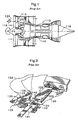
- Patent Document 1 discloses a retainer assembly 126 for retaining the fan blades 122 in the rotor disk 124. As shown in Fig. 2 , the retainer assembly 126 includes the rotor disk 124, a first blade retainer 138, and a second blade retainer 144.
- the rotor disk 124 includes a plurality of dovetail posts 128 which are spaced at a predetermined angular interval in a circumferential direction, and a dovetail groove 130 is formed therebetween.
- Each fan blade 122 includes a dovetail 132 fitted to the dovetail groove 130 in an axial direction, and the dovetail 132 is immovably retained in a radial direction by the dovetail post 128.
- the first blade retainer 138 is provided so as to prevent the fan blade 122 from moving in an axial forward direction (upstream direction).
- the first blade retainer 138 includes a fixed plate 140 fixed to the rotor disk 124 so as to immovably retain the fan blade 122 in the dovetail groove 130 in an axial direction.
- the fixed plate 140 is inserted in an outward radial direction into a pair of grooves 142 formed in the adjacent dovetail posts 128.
- the second blade retainer 144 is provided so as to prevent the axial movement of the fan blades 122 by serving as a chock after the fan blades 122 move by a predetermined distance in a case where the axial movement of the fan blades 122 cannot be prevented by the first blade retainer 138.
- both the first blade retainer 138 and the second blade retainer 144 disperse the axial forward shock energy acting on the fan blades 122 so that each fan blade 122 is retained in the dovetail grooves 130.
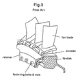
- Fig. 3 is a schematic view illustrating a dovetail structure according to a conventional art.
- a fan disk or a spinner a circular disk
- a conventional dovetail structure in which a dovetail part is formed in a root portion of the fan blade so as to extend in a longitudinal direction and the dovetail part is fitted to a dovetail groove formed in the periphery of a disk.
- a member called a retainer was fastened to a front portion of the blade by a bolt and a disk.
- Examples of the retainer include a circular-ring type for functioning with respect to a plurality of blades and a plate type for functioning with respect to each of the blades.
- an object of the invention is to provide a fan blade retaining structure capable of surely preventing a fan blade from coming off from a disk even when an axial forward load acts on the fan blade upon breaking the fan blade, of being easily designed with high estimation precision of stress, and of enabling a fastening bolt to be lighter in weight, smaller in size, and fewer in number than a conventional fastening bolt, thereby reducing the number of components. Accordingly, it is possible to provide the fan blade retaining structure capable of realizing a decrease in weight and cost.
- a fan blade retaining structure in which a plurality of fan blades is configured to be attached to an outer periphery of a disk rotationally driven by a turbine, wherein the disk includes a plurality of dovetail grooves configured to be spaced at a predetermined angular interval in a circumferential direction and to extend in an axial direction, wherein each of the fan blades includes a dovetail part configured to be fitted to each of the dovetail grooves in an axial direction and capable of transmitting a centrifugal force produced during rotation to the disk, and a projecting part configured to be positioned in rear of the dovetail part and to project outward more than the dovetail groove in a circumferential direction, and wherein the projecting part is set to be such a size that the projecting part does not interfere with the dovetail groove when the dovetail part is positioned on the inner side of the dovetail groove in a radial direction.
- the fan blade retaining structure further includes an auxiliary retainer configured to be fixed to the disk and to prevent the fan blade from moving in an axial forward direction.
- the projecting part is formed by cutting, welding or pressure bonding.
- the fan blade retaining structure desirably includes a fan spacer configured to be inserted between a lower surface of the dovetail part and a bottom surface of the dovetail groove so as to position the dovetail part on the outer side in a radial direction.
- the dovetail part disposed in the dovetail groove is pressed by a centrifugal force to the outer side in a radial direction. Since the fan blade includes the projecting part which is positioned in rear of the dovetail part and projects outward more than the dovetail groove in a circumferential direction, during the rotation, the projecting part serves as a come-off prevention element for restraining a relative displacement of the fan blade and the disk.
- a stress occurring in the projecting part by the axial forward load mainly corresponds to an axial shear stress and a stress occurring in the disk by the axial forward load mainly corresponds to an axial compressive stress, it is possible to accurately estimate an internal stress occurring in the projecting part and the disk.
- the projecting part is set to be such a size that the projecting part does not interfere with the dovetail groove when the dovetail part is positioned on the inner side of the dovetail groove in a radial direction, the projecting part does not interfere with the disk by positioning the fan blade to be adjacent to the inner side in a radial direction upon stopping the engine, thereby facilitating the assembling operation and the disassembling operation.
- the projecting part comes into contact with the rear surface of the disk so as to transmit the axial forward load to the disk, and thus the axial forward load does not act on the auxiliary retainer in the event of FBO.
- the auxiliary retainer may have strength for withstanding the comparatively small axial forward load produced when the dovetail part is positioned on the inner side of the dovetail groove in a radial direction.
- the fastener bolt, nut, and the like
- the projecting part of the fan blade is inserted to pass through the dovetail groove from the front side of the disk upon stopping the engine in a state where the fan blade is positioned to be adjacent to the inner side in a radial direction so that the projecting part does not interfere with the disk.
- the fan spacer is inserted between the lower surface of the dovetail part and the bottom surface of the dovetail groove so that the dovetail part of the fan blade is positioned on the outer side in a radial direction.
- the axial forward load does not acts on the fastener (bolt, nut, and the like) for fastening the auxiliary retainer and the auxiliary retainer, and thus it is possible to more reduce the weight, the size, and the number of the fastening bolt.
- Fig. 4 is a transverse sectional view illustrating a fan part of an engine provided with a fan blade retaining structure according to the invention, in which only the upper side of a shaft center 1 is shown.
- the fan blade retaining structure according to the invention is configured such that a plurality of fan blades 20 are attached to the outer periphery of a disk 10 which is rotationally driven by a turbine (not shown).
- Reference numeral 1 denotes the shaft center of the rotary shaft of the disk 10 and the fan blades 20
- Reference numeral 2 denotes an air flow passage
- Reference numeral 3 denotes the inner peripheral surface of the air flow passage
- Reference numeral 4 denotes an intake air flow
- Reference numeral 5 denotes an axial forward power acting on the fan blades 20 in the event of FBO.
- the fan blade retaining structure includes the disk 10, the fan blades 20, an auxiliary retainer 30, and a fastener 40.
- the disk 10 includes a plurality of dovetail grooves 12 which are spaced at a predetermined angular interval in a circumferential direction and extends in an axial direction. Although it is desirable that the number of the dovetail grooves 12 is the same as that of the fan blades 20, a plurality (two or more) of fan blades 20 may be attached to one dovetail groove 12.
- the dovetail grooves 12 are parallel to a shaft center 1 of a rotary shaft, but may be inclined with respect to the shaft center 1.
- each of the dovetail grooves 12 may be formed into a linear shape or a circular arc shape so long as each of the fan blades 20 is inserted and fitted in an axial direction from the front side.
- Fig. 5 is a perspective view illustrating a state where the fan blade according to the invention is detached.
- the fan blade 20 includes a dovetail part 22 which is formed in the inner end in a radial direction so as to be fitted to the dovetail groove 12.
- the dovetail part 22 is configured to be fitted to the dovetail groove 12 in an axial direction from the front side and to transmit a centrifugal force acting on the fan blade 20 produced during rotation to the disk 10.
- the fan blade 20 further includes a projecting part 24 which is positioned in rear of the dovetail part 22 and projects outward more than the dovetail groove 12 in a circumferential direction.
- the projecting part 24 is set to be such a size that the projecting part 24 does not interfere with the dovetail groove 12 when the dovetail part 22 is position on the inner side of the dovetail groove 12 in a radial direction.
- the projecting part 24 may be integrally formed with the dovetail part 22 by cutting or may be integrally formed with the dovetail part 22 by welding or pressure bonding.
- the auxiliary retainer 30 is fixed to the front edge of the disk 10 by a fastener 40, and the rear edge thereof comes into contact with the front surface of the dovetail part 22 so as to prevent the fan blade 20 from moving in an axial forward direction.
- the auxiliary retainer 30 may be of a circular-ring type for functioning with respect to a plurality of dovetail parts 22 or a plate type for functioning with respect to each of the dovetail parts 22.
- the fastener 40 includes a bolt 41 and a nut 42 which are screw-connected to each other while passing through a through hole formed in the auxiliary retainer 30 and a through hole formed in the flange part 14 of the disk 10.
- the fan blade retaining structure according to the invention further includes a fan spacer 44.
- the fan spacer 44 is inserted between a lower surface of the dovetail part 22 and a bottom surface of the dovetail groove 12 so as to position the dovetail part 22 on the outer side in a radial direction.
- Fig. 6A is a view taken along the line A-A shown in Fig. 4 in a state where the fan blade 20 is being mounted.
- Fig. 6B is a view taken along the line A-A shown in Fig. 4 in a state where the fan blade 20 is completely mounted.
- the projecting part 24 of the fan blade 20 is set to be such a size that the projecting part 24 does not interfere with the dovetail groove 12 when the dovetail part 22 of the fan blade 20 is positioned on the inner side of the dovetail groove 12 in a radial direction.
- the projecting part 24 of the fan blade 20 can be inserted to pass through the dovetail groove 12 from the front side of the disk 10 upon stopping the engine in a state where the fan blade 20 is positioned to be adjacent to the inner side in a radial direction so that the projecting part 24 does not interfere with the disk 10.
- the fan spacer 44 is inserted between the lower surface of the dovetail part 22 and the bottom surface of the dovetail groove 12 so that the dovetail part 22 of the fan blade 20 is positioned on the outer side in a radial direction as shown in Fig. 6B .
- the fan spacer 44 is not an essential component, but the assembling operation can be easily carried out by fixing the fan blade 20 to an operation position upon stopping the engine in terms of the fan spacer.
- the dovetail part 22 disposed in the dovetail groove 12 is pressed by a centrifugal force to the outer side in a radial direction. Since the fan blade 20 includes the projecting part 24 which is positioned in rear of the dovetail part 22 and projects outward more than the dovetail groove in a circumferential direction, during the rotation, the projecting part 24 depicted by the slanted lines shown in Fig. 6B serves as a come-off prevention element for restraining a relative displacement of the fan blade 20 and the disk 10.
- a stress occurring in the projecting part 24 by the axial forward load mainly corresponds to an axial shear stress and a stress occurring in the disk 10 by the axial forward load mainly corresponds to an axial compressive stress, it is possible to accurately estimate an internal stress occurring in the projecting part 24 and the disk 10.
- the projecting part 24 is set to be such a size that the projecting part does not interfere with the dovetail groove 12 when the dovetail part 22 is positioned on the inner side of the dovetail groove 12 in a radial direction, the projecting part 24 does not interfere with the disk 10 by positioning the fan blade 20 to be adjacent to the inner side in a radial direction upon stopping the engine, thereby facilitating the assembling operation and the disassembling operation.
- the projecting part 24 comes into contact with the rear surface 10b of the disk 10 so as to transmit the axial forward load to the disk 10, and thus the axial forward load does not act on the auxiliary retainer 30 in the event of FBO.
- the auxiliary retainer 30 may have strength for withstanding the comparatively small axial forward load produced when the dovetail part 22 is positioned on the inner side of the dovetail groove 12 in a radial direction.
- the fastener bolt, nut, and the like
- the axial forward load does not acts on the fastener (bolt, nut, and the like) for fastening the auxiliary retainer and the auxiliary retainer, and thus it is possible to more reduce the weight, the size, and the number of fastening bolt.
Landscapes
- Engineering & Computer Science (AREA)
- Mechanical Engineering (AREA)
- General Engineering & Computer Science (AREA)
- Structures Of Non-Positive Displacement Pumps (AREA)
Description
- The present invention relates to a fan blade retaining structure for preventing a fan blade from coming off from a disk even when an axial forward load acts on the fan blade upon breaking the fan blade. A fan blade retaining structure according to the preamble of
claim 1 is known fromFR 2 524 933 A1 -
Fig. 1 is a schematic view illustrating aturbofan engine 110 for an airplane. Theengine 110 includes afan assembly 112 which is coaxially disposed with respect to acenter shaft 116 and is driven by acore engine 114. During the operation of theengine 110,external air 118 is sucked by thefan assembly 112 so as to produce a thrust for enabling an airplane to fly. - When the airplane having the above-described
engine 110 takes off or lands, for example, a comparativelylarge bird 120 may be sucked into thefan assembly 112. In this case, thebird 120 impacts onfan blades 122 extending outward from arotor disk 124 in a radial direction, so that a part of thefan blades 122 is broken and scattered. Additionally, alien materials except for the bird may be sucked into the fan assembly to thereby damage components. In addition to the supposition, thefan blades 122 or a part thereof may be broken and scattered due to a large load or the like. Hereinafter, such a phenomenon will be referred to as FBO (Fan Blade Off). - In the event of the FBO, a part of the
fan blades 122 may be scattered to collide against the adjacentother fan blades 122, so that an axial forward (upstream) shock power acts on thefan blades 122. - Since the axial forward shock power acting on the
fan blades 122 acts in a direction in which thefan blades 122 come off from therotor disk 124, thefan assembly 112 needs to be provided with a structure capable of retaining thefan blades 122 in therotor disk 124 even when the axial forward shock power acts on thefan blades 122. -
Patent Document 1 has already proposed a fan blade retainer for satisfying the above-described requirements. -
Patent Document 1 discloses aretainer assembly 126 for retaining thefan blades 122 in therotor disk 124. As shown inFig. 2 , theretainer assembly 126 includes therotor disk 124, afirst blade retainer 138, and asecond blade retainer 144. - The
rotor disk 124 includes a plurality ofdovetail posts 128 which are spaced at a predetermined angular interval in a circumferential direction, and adovetail groove 130 is formed therebetween. Eachfan blade 122 includes adovetail 132 fitted to thedovetail groove 130 in an axial direction, and thedovetail 132 is immovably retained in a radial direction by thedovetail post 128. With the above-described configuration, a centrifugal force produced during rotation of thefan blades 122 is transmitted to therotor disk 124 via thedovetail post 128. - The
first blade retainer 138 is provided so as to prevent thefan blade 122 from moving in an axial forward direction (upstream direction). Thefirst blade retainer 138 includes afixed plate 140 fixed to therotor disk 124 so as to immovably retain thefan blade 122 in thedovetail groove 130 in an axial direction. Thefixed plate 140 is inserted in an outward radial direction into a pair ofgrooves 142 formed in theadjacent dovetail posts 128. - The
second blade retainer 144 is provided so as to prevent the axial movement of thefan blades 122 by serving as a chock after thefan blades 122 move by a predetermined distance in a case where the axial movement of thefan blades 122 cannot be prevented by thefirst blade retainer 138. With the above-described configuration, both thefirst blade retainer 138 and thesecond blade retainer 144 disperse the axial forward shock energy acting on thefan blades 122 so that eachfan blade 122 is retained in thedovetail grooves 130. - [Patent Document 1]
-
US Patent No. 5,282,720 'Fan blade retainer' -
Fig. 3 is a schematic view illustrating a dovetail structure according to a conventional art. As shown in the drawing ofFig. 3 , it is necessary to attach the fan blades of the turbofan engine to a peripheral portion of a circular disk (called a fan disk or a spinner) rotationally driven by a turbine. For this reason, in the past, there was adopted a conventional dovetail structure in which a dovetail part is formed in a root portion of the fan blade so as to extend in a longitudinal direction and the dovetail part is fitted to a dovetail groove formed in the periphery of a disk. - In addition, in order to prevent the fan blade from coming off from the dovetail groove due to the axial forward power, in the past, a member called a retainer was fastened to a front portion of the blade by a bolt and a disk.
- Examples of the retainer include a circular-ring type for functioning with respect to a plurality of blades and a plate type for functioning with respect to each of the blades.
- However, in case of the circular-ring type retainer, since a gap between an action portion of a load and a fastening portion such as a bolt and a nut is long, a problem arises in that the stress acting on the bolt due to the load is difficult to be estimated and the retainer is difficult to be designed. Meanwhile, in case of the plate type retainer, since the retainer is mounted to each fan blade, a problem arises in that operability is poor. For this reason, in both cases of the circular-ring type retainer and the plate type retainer, a problem arises in that a decrease in weight is difficult to be achieved and a cost is high.
- In addition, in case of the retainer assembly described in
Patent Document 1, although both thefirst blade retainer 138 and thesecond blade retainer 144 can disperse the axial forward shock energy acting on thefan blades 122 so that eachfan blade 122 is retained in thedovetail groove 130, a problem arises in that the structure is complex and a manufacturing cost is high. - In the retainer assembly, since it is necessary to provide a plurality of
first blade retainers 138 and thesecond blade retainers 144, a problem arises in that the operability during an assembling operation is poor. - The present invention is contrived in consideration of the above-described problems. That is, an object of the invention is to provide a fan blade retaining structure capable of surely preventing a fan blade from coming off from a disk even when an axial forward load acts on the fan blade upon breaking the fan blade, of being easily designed with high estimation precision of stress, and of enabling a fastening bolt to be lighter in weight, smaller in size, and fewer in number than a conventional fastening bolt, thereby reducing the number of components. Accordingly, it is possible to provide the fan blade retaining structure capable of realizing a decrease in weight and cost.
- According to the invention, there is provided a fan blade retaining structure in which a plurality of fan blades is configured to be attached to an outer periphery of a disk rotationally driven by a turbine, wherein the disk includes a plurality of dovetail grooves configured to be spaced at a predetermined angular interval in a circumferential direction and to extend in an axial direction, wherein each of the fan blades includes a dovetail part configured to be fitted to each of the dovetail grooves in an axial direction and capable of transmitting a centrifugal force produced during rotation to the disk, and a projecting part configured to be positioned in rear of the dovetail part and to project outward more than the dovetail groove in a circumferential direction, and wherein the projecting part is set to be such a size that the projecting part does not interfere with the dovetail groove when the dovetail part is positioned on the inner side of the dovetail groove in a radial direction.
- According to a preferred embodiment of the invention, the fan blade retaining structure further includes an auxiliary retainer configured to be fixed to the disk and to prevent the fan blade from moving in an axial forward direction.
- The projecting part is formed by cutting, welding or pressure bonding.
- The fan blade retaining structure desirably includes a fan spacer configured to be inserted between a lower surface of the dovetail part and a bottom surface of the dovetail groove so as to position the dovetail part on the outer side in a radial direction.
- According to the configuration of the invention, during the rotation of the fan blade, the dovetail part disposed in the dovetail groove is pressed by a centrifugal force to the outer side in a radial direction. Since the fan blade includes the projecting part which is positioned in rear of the dovetail part and projects outward more than the dovetail groove in a circumferential direction, during the rotation, the projecting part serves as a come-off prevention element for restraining a relative displacement of the fan blade and the disk.
- Accordingly, even when the axial forward load acts on the fan blade upon breaking the fan blade, it is possible to transmit the axial forward load to the disk in such a manner that the projecting part projecting outward more than the dovetail groove in a circumferential direction comes into contact with a rear surface of the disk.
- Since a stress occurring in the projecting part by the axial forward load mainly corresponds to an axial shear stress and a stress occurring in the disk by the axial forward load mainly corresponds to an axial compressive stress, it is possible to accurately estimate an internal stress occurring in the projecting part and the disk.
- Since the projecting part and the disk are prevented from being broken by setting the internal stress to a sufficiently small stress, it is possible to surely prevent the fan blade from coming off from the disk.
- Since the projecting part is set to be such a size that the projecting part does not interfere with the dovetail groove when the dovetail part is positioned on the inner side of the dovetail groove in a radial direction, the projecting part does not interfere with the disk by positioning the fan blade to be adjacent to the inner side in a radial direction upon stopping the engine, thereby facilitating the assembling operation and the disassembling operation.
- Accordingly, it is possible to integrally form the projecting part with the dovetail part, and thus to reduce the number of components.
- In addition, when a centrifugal force is large upon using the auxiliary retainer having the same configuration as that of a conventional auxiliary retainer for preventing the fan blade from moving in an axial forward direction, the projecting part comes into contact with the rear surface of the disk so as to transmit the axial forward load to the disk, and thus the axial forward load does not act on the auxiliary retainer in the event of FBO.
- Accordingly, the auxiliary retainer may have strength for withstanding the comparatively small axial forward load produced when the dovetail part is positioned on the inner side of the dovetail groove in a radial direction. Thus, since the large axial forward load does not act on the fastener (bolt, nut, and the like) for fastening the auxiliary retainer to the flange part, it is possible to more reduce the weight, the size, and the number of the fastening bolts than a conventional fastening bolt, and thus to reduce the number of components. Accordingly, it is possible to realize a decrease in weight and cost.
- In addition, the projecting part of the fan blade is inserted to pass through the dovetail groove from the front side of the disk upon stopping the engine in a state where the fan blade is positioned to be adjacent to the inner side in a radial direction so that the projecting part does not interfere with the disk. Subsequently, the fan spacer is inserted between the lower surface of the dovetail part and the bottom surface of the dovetail groove so that the dovetail part of the fan blade is positioned on the outer side in a radial direction.
- Accordingly, it is possible to easily carry out the assembling operation by fixing the fan blade to the operation position upon stopping the engine. Also, it is possible to transmit the axial forward load to the disk by allowing the projecting part to come into contact with the rear surface of the disk even when the centrifugal force is small. Hence, the axial forward load does not acts on the fastener (bolt, nut, and the like) for fastening the auxiliary retainer and the auxiliary retainer, and thus it is possible to more reduce the weight, the size, and the number of the fastening bolt.
-
-
Fig. 1 is a schematic view illustrating a turbofan engine for an airplane. -
Fig. 2 is a configuration view illustrating a fan blade retainer disclosed inPatent Document 1. -
Fig. 3 is a schematic view illustrating a dovetail structure according to a prior art. -
Fig. 4 is a transverse sectional view illustrating a fan part of an engine provided with a fan blade retaining structure according to the invention. -
Fig. 5 is a perspective view illustrating a state where a fan blade according to the invention is detached. -
Fig. 6A is a view taken along the line A-A shown inFig. 4 in a state where afan blade 20 is being mounted. -
Fig. 6B is a view taken along the line A-A shown inFig. 4 in a state where thefan blade 20 is completely mounted. - Hereinafter, preferred embodiments of the invention will be described in detail with reference to the accompanying drawings. In addition, in the respective drawings, the same reference numerals are given to the same components and the repetitive description thereof will be omitted.
-
Fig. 4 is a transverse sectional view illustrating a fan part of an engine provided with a fan blade retaining structure according to the invention, in which only the upper side of ashaft center 1 is shown. The fan blade retaining structure according to the invention is configured such that a plurality offan blades 20 are attached to the outer periphery of adisk 10 which is rotationally driven by a turbine (not shown). - In addition, in the drawing of
Fig. 4 ,Reference numeral 1 denotes the shaft center of the rotary shaft of thedisk 10 and thefan blades 20,Reference numeral 2 denotes an air flow passage,Reference numeral 3 denotes the inner peripheral surface of the air flow passage,Reference numeral 4 denotes an intake air flow, andReference numeral 5 denotes an axial forward power acting on thefan blades 20 in the event of FBO. - As shown in the drawing of
Fig. 4 , the fan blade retaining structure according to the invention includes thedisk 10, thefan blades 20, anauxiliary retainer 30, and afastener 40. - The
disk 10 includes a plurality ofdovetail grooves 12 which are spaced at a predetermined angular interval in a circumferential direction and extends in an axial direction. Although it is desirable that the number of thedovetail grooves 12 is the same as that of thefan blades 20, a plurality (two or more) offan blades 20 may be attached to onedovetail groove 12. - In this example, the
dovetail grooves 12 are parallel to ashaft center 1 of a rotary shaft, but may be inclined with respect to theshaft center 1. In addition, each of thedovetail grooves 12 may be formed into a linear shape or a circular arc shape so long as each of thefan blades 20 is inserted and fitted in an axial direction from the front side. -
Fig. 5 is a perspective view illustrating a state where the fan blade according to the invention is detached. - In
Figs. 4 and5 , thefan blade 20 includes adovetail part 22 which is formed in the inner end in a radial direction so as to be fitted to thedovetail groove 12. Thedovetail part 22 is configured to be fitted to thedovetail groove 12 in an axial direction from the front side and to transmit a centrifugal force acting on thefan blade 20 produced during rotation to thedisk 10. - The
fan blade 20 further includes a projectingpart 24 which is positioned in rear of thedovetail part 22 and projects outward more than thedovetail groove 12 in a circumferential direction. - The projecting
part 24 is set to be such a size that the projectingpart 24 does not interfere with thedovetail groove 12 when thedovetail part 22 is position on the inner side of thedovetail groove 12 in a radial direction. - In addition, the projecting
part 24 may be integrally formed with thedovetail part 22 by cutting or may be integrally formed with thedovetail part 22 by welding or pressure bonding. - In
Fig. 4 , theauxiliary retainer 30 is fixed to the front edge of thedisk 10 by afastener 40, and the rear edge thereof comes into contact with the front surface of thedovetail part 22 so as to prevent thefan blade 20 from moving in an axial forward direction. Theauxiliary retainer 30 may be of a circular-ring type for functioning with respect to a plurality ofdovetail parts 22 or a plate type for functioning with respect to each of thedovetail parts 22. - The
fastener 40 includes abolt 41 and anut 42 which are screw-connected to each other while passing through a through hole formed in theauxiliary retainer 30 and a through hole formed in theflange part 14 of thedisk 10. - In
Fig. 4 , the fan blade retaining structure according to the invention further includes afan spacer 44. Thefan spacer 44 is inserted between a lower surface of thedovetail part 22 and a bottom surface of thedovetail groove 12 so as to position thedovetail part 22 on the outer side in a radial direction. -
Fig. 6A is a view taken along the line A-A shown inFig. 4 in a state where thefan blade 20 is being mounted.Fig. 6B is a view taken along the line A-A shown inFig. 4 in a state where thefan blade 20 is completely mounted. - As described above, as shown in
Fig. 6A , the projectingpart 24 of thefan blade 20 is set to be such a size that the projectingpart 24 does not interfere with thedovetail groove 12 when thedovetail part 22 of thefan blade 20 is positioned on the inner side of thedovetail groove 12 in a radial direction. - Accordingly, the projecting
part 24 of thefan blade 20 can be inserted to pass through thedovetail groove 12 from the front side of thedisk 10 upon stopping the engine in a state where thefan blade 20 is positioned to be adjacent to the inner side in a radial direction so that the projectingpart 24 does not interfere with thedisk 10. Subsequently, thefan spacer 44 is inserted between the lower surface of thedovetail part 22 and the bottom surface of thedovetail groove 12 so that thedovetail part 22 of thefan blade 20 is positioned on the outer side in a radial direction as shown inFig. 6B . - In addition, in this invention, the
fan spacer 44 is not an essential component, but the assembling operation can be easily carried out by fixing thefan blade 20 to an operation position upon stopping the engine in terms of the fan spacer. - According to the above-described configuration, during the rotation of the
fan blade 20, thedovetail part 22 disposed in thedovetail groove 12 is pressed by a centrifugal force to the outer side in a radial direction. Since thefan blade 20 includes the projectingpart 24 which is positioned in rear of thedovetail part 22 and projects outward more than the dovetail groove in a circumferential direction, during the rotation, the projectingpart 24 depicted by the slanted lines shown inFig. 6B serves as a come-off prevention element for restraining a relative displacement of thefan blade 20 and thedisk 10. - Accordingly, even when the axial forward load acts on the
fan blade 20 upon breaking thefan blade 20, it is possible to transmit the axial forward load to thedisk 10 in such a manner that the projectingpart 24 projecting outward more than thedovetail groove 12 in a circumferential direction comes into contact with arear surface 10b of thedisk 10. - Since a stress occurring in the projecting
part 24 by the axial forward load mainly corresponds to an axial shear stress and a stress occurring in thedisk 10 by the axial forward load mainly corresponds to an axial compressive stress, it is possible to accurately estimate an internal stress occurring in the projectingpart 24 and thedisk 10. - Since the projecting
part 24 and thedisk 10 are prevented from being broken by setting the internal stress to a sufficiently small stress, it is possible to surely prevent thefan blade 20 from coming off from thedisk 10. - Since the projecting
part 24 is set to be such a size that the projecting part does not interfere with thedovetail groove 12 when thedovetail part 22 is positioned on the inner side of thedovetail groove 12 in a radial direction, the projectingpart 24 does not interfere with thedisk 10 by positioning thefan blade 20 to be adjacent to the inner side in a radial direction upon stopping the engine, thereby facilitating the assembling operation and the disassembling operation. - Accordingly, it is possible to integrally form the projecting
part 24 with thedovetail part 22, and thus to reduce the number of components. - In addition, when a centrifugal force is large upon using the
auxiliary retainer 30 having the same configuration as that of a conventional auxiliary retainer for preventing thefan blade 20 from moving in an axial forward direction, the projectingpart 24 comes into contact with therear surface 10b of thedisk 10 so as to transmit the axial forward load to thedisk 10, and thus the axial forward load does not act on theauxiliary retainer 30 in the event of FBO. - Accordingly, the
auxiliary retainer 30 may have strength for withstanding the comparatively small axial forward load produced when thedovetail part 22 is positioned on the inner side of thedovetail groove 12 in a radial direction. Thus, since the large axial forward load does not act on the fastener (bolt, nut, and the like) for fastening the auxiliary retainer to the flange part, it is possible to more reduce the weight, the size, and the number of the fastening bolt than a conventional fastening bolt, and thus to reduce the number of components. Accordingly, it is possible to realize a decrease in weight and cost. - In addition, it is possible to position the
dovetail part 22 of thefan blade 20 to the outer side in a radial direction by inserting thefan spacer 44 between the lower surface of thedovetail part 22 and the bottom surface of thedovetail groove 12. - Accordingly, it is possible to easily carry out the assembling operation by fixing the fan blade to the operation position upon stopping the engine. Also, it is possible to transmit the axial forward load to the disk by allowing the projecting part to come into contact with the rear surface of the disk even when the centrifugal force is small. Hence, the axial forward load does not acts on the fastener (bolt, nut, and the like) for fastening the auxiliary retainer and the auxiliary retainer, and thus it is possible to more reduce the weight, the size, and the number of fastening bolt.
Claims (4)
- A fan blade retaining structure in which a plurality of fan blades (20) is configured to be attached to an outer periphery of a disk (10) rotationally driven by a turbine,
wherein the disk (10) includes a plurality of dovetail grooves (12) configured to be spaced at a predetermined angular interval in a circumferential direction and to extend in an axial direction,
wherein each of the fan blades (20) includes a dovetail part (22) configured to be fitted to each of the dovetail grooves (12) in an axial direction and capable of transmitting a centrifugal force produced during rotation to the disk (10), and a projecting part (24) configured to be positioned in rear of the dovetail part (22), and
characterized in that
the projecting part (24) is configured to project outward more than the dovetail groove (12) in a circumferential direction, and is set to be such a size that the projecting part (24) does not interfere with the dovetail groove (12) when the dovetail part (22) is positioned on the inner side of the dovetail groove (12) in a radial direction. - The fan blade retaining structure according to Claim 1, further comprising:an auxiliary retainer (30) configured to be fixed to the disk (10) and to prevent the fan blade (20) from moving in an axial forward direction.
- The fan blade retaining structure according to Claim 1, wherein the projecting part (24) is formed by cutting, welding or pressure bonding.
- The fan blade retaining structure according to Claim 1, further comprising:a fan spacer (44) configured to be inserted between a lower surface of the dovetail part (22) and a bottom surface of the dovetail groove (12) so as to position the dovetail part (22) on the outer side in a radial direction.
Applications Claiming Priority (2)
| Application Number | Priority Date | Filing Date | Title |
|---|---|---|---|
| JP2006067623A JP2007247407A (en) | 2006-03-13 | 2006-03-13 | Holding structure of fan blade |
| PCT/JP2007/054876 WO2007105702A1 (en) | 2006-03-13 | 2007-03-13 | Holding structure of fan blade |
Publications (3)
| Publication Number | Publication Date |
|---|---|
| EP1995468A1 EP1995468A1 (en) | 2008-11-26 |
| EP1995468A4 EP1995468A4 (en) | 2013-01-02 |
| EP1995468B1 true EP1995468B1 (en) | 2014-05-07 |
Family
ID=38509522
Family Applications (1)
| Application Number | Title | Priority Date | Filing Date |
|---|---|---|---|
| EP07738348.7A Active EP1995468B1 (en) | 2006-03-13 | 2007-03-13 | Holding structure of fan blade |
Country Status (5)
| Country | Link |
|---|---|
| US (1) | US20090053065A1 (en) |
| EP (1) | EP1995468B1 (en) |
| JP (1) | JP2007247407A (en) |
| CA (1) | CA2637278A1 (en) |
| WO (1) | WO2007105702A1 (en) |
Families Citing this family (12)
| Publication number | Priority date | Publication date | Assignee | Title |
|---|---|---|---|---|
| US8182230B2 (en) * | 2009-01-21 | 2012-05-22 | Pratt & Whitney Canada Corp. | Fan blade preloading arrangement and method |
| US8979502B2 (en) | 2011-12-15 | 2015-03-17 | Pratt & Whitney Canada Corp. | Turbine rotor retaining system |
| US8974188B2 (en) | 2012-03-06 | 2015-03-10 | Hamilton Sundstrand Corporation | Blade clip |
| US10077674B2 (en) | 2015-06-23 | 2018-09-18 | General Electric Company | Trunnion retention for a turbine engine |
| CN105221478B (en) * | 2015-09-17 | 2018-11-13 | 中国航空工业集团公司沈阳发动机设计研究所 | A kind of compressor rotor blade locating snap ring and the impeller with it |
| KR101882109B1 (en) * | 2016-12-23 | 2018-07-25 | 두산중공업 주식회사 | Gas turbine |
| GB201704832D0 (en) * | 2017-02-20 | 2017-05-10 | Rolls Royce Plc | Fan |
| CN109555727B (en) * | 2019-01-07 | 2024-06-07 | 奥卡冷却系统(天津)有限公司 | Connector and combined fan |
| CN110836199A (en) * | 2019-12-12 | 2020-02-25 | 中国船舶重工集团公司第七0三研究所 | A high-pressure-ratio compressed air moving blade and a wheel disc connection structure |
| CN111456815A (en) * | 2020-04-30 | 2020-07-28 | 上海建桥学院 | A roulette assembly and its five-axis machining method |
| FR3127255B1 (en) * | 2021-09-23 | 2025-04-25 | Safran Aircraft Engines | Rotating assembly for turbomachine |
| US12264590B2 (en) | 2023-08-08 | 2025-04-01 | General Electric Company | Fan assembly for an engine having redundant trunnion retention |
Family Cites Families (15)
| Publication number | Priority date | Publication date | Assignee | Title |
|---|---|---|---|---|
| US2751189A (en) * | 1950-09-08 | 1956-06-19 | United Aircraft Corp | Blade fastening means |
| US3834831A (en) * | 1973-01-23 | 1974-09-10 | Westinghouse Electric Corp | Blade shank cooling arrangement |
| CH655547B (en) * | 1981-11-10 | 1986-04-30 | ||
| FR2524932A1 (en) * | 1982-04-08 | 1983-10-14 | Snecma | DEVICE FOR AXIAL RETENTION OF BLADE FEET IN A TURBOMACHINE DISC |
| FR2524933B1 (en) * | 1982-04-13 | 1987-02-20 | Snecma | AXIAL LOCKING DEVICE FOR TURBINE OR COMPRESSOR ROTOR BLADES |
| US5123813A (en) * | 1991-03-01 | 1992-06-23 | General Electric Company | Apparatus for preloading an airfoil blade in a gas turbine engine |
| US5282720A (en) * | 1992-09-15 | 1994-02-01 | General Electric Company | Fan blade retainer |
| FR2715975B1 (en) * | 1994-02-10 | 1996-03-29 | Snecma | Turbomachine rotor with axial or inclined through blade grooves. |
| GB2299834B (en) * | 1995-04-12 | 1999-09-08 | Rolls Royce Plc | Gas turbine engine rotary disc |
| JPH10110601A (en) * | 1996-10-08 | 1998-04-28 | Hitachi Ltd | How to keep moving blade |
| JPH10184308A (en) * | 1996-12-24 | 1998-07-14 | Hitachi Ltd | Gas turbine engine rotor |
| JPH10299407A (en) * | 1997-04-22 | 1998-11-10 | Hitachi Ltd | Gas turbine engine rotor |
| JP2002221003A (en) * | 2001-01-25 | 2002-08-09 | Toyota Motor Corp | Rotor balancing method, apparatus therefor, and rotor |
| FR2888897B1 (en) * | 2005-07-21 | 2007-10-19 | Snecma | DEVICE FOR DAMPING THE VIBRATION OF AN AXIAL RETAINING RING OF BLOWER BLADES OF A TURBOMACHINE |
| JP4807113B2 (en) * | 2006-03-14 | 2011-11-02 | 株式会社Ihi | Fan dovetail structure |
-
2006
- 2006-03-13 JP JP2006067623A patent/JP2007247407A/en active Pending
-
2007
- 2007-03-13 US US12/162,854 patent/US20090053065A1/en not_active Abandoned
- 2007-03-13 EP EP07738348.7A patent/EP1995468B1/en active Active
- 2007-03-13 CA CA002637278A patent/CA2637278A1/en not_active Abandoned
- 2007-03-13 WO PCT/JP2007/054876 patent/WO2007105702A1/en not_active Ceased
Also Published As
| Publication number | Publication date |
|---|---|
| EP1995468A1 (en) | 2008-11-26 |
| CA2637278A1 (en) | 2007-09-20 |
| JP2007247407A (en) | 2007-09-27 |
| EP1995468A4 (en) | 2013-01-02 |
| US20090053065A1 (en) | 2009-02-26 |
| WO2007105702A1 (en) | 2007-09-20 |
Similar Documents
| Publication | Publication Date | Title |
|---|---|---|
| EP1995468B1 (en) | Holding structure of fan blade | |
| EP1995467B1 (en) | Holding structure of fan blade | |
| EP1209322B1 (en) | Blade spacer and rotor disk assembly comprising such a spacer | |
| EP2570600B1 (en) | Turbine rotor blade assembly and method of assembling same | |
| US6634863B1 (en) | Circular arc multi-bore fan disk assembly | |
| EP1209320B1 (en) | Fan disk configuration | |
| US6447250B1 (en) | Non-integral fan platform | |
| US6457942B1 (en) | Fan blade retainer | |
| JP6131010B2 (en) | Metal fan blade platform | |
| JP5283388B2 (en) | Rotor disc for turbomachine fan | |
| JP2016509646A (en) | Non-integrated fan blade platform | |
| EP2871331B1 (en) | Method for tight control of bolt holes in fan assembly | |
| EP2964896B1 (en) | System for preventing leakage in a turbine, corresponding method of preventing air leakage | |
| EP2902592B1 (en) | Gas turbine engine | |
| EP2672070B1 (en) | Nozzle Mounting and Sealing Assembly and Method of Mounting and Sealing a Nozzle Assembly | |
| EP2730503B1 (en) | Flexbeam rotor attachment to rotor blade | |
| EP3222857B1 (en) | Mechanical joint with a flanged retainer | |
| EP3056681B1 (en) | Method of making a turbine wheel axial retention device | |
| RU2272180C2 (en) | Fan blade | |
| US9102413B2 (en) | Fastening device particularly suitable for the fastening between an air intake and an engine of an aircraft nacelle | |
| US8899935B2 (en) | Fan rotor for an airplane turbojet | |
| EP2944771B1 (en) | Fan containment system of a gas turbine engine | |
| EP1642007B1 (en) | Turbine shroud segment | |
| JP5561461B2 (en) | Rotor blade holding structure | |
| EP3056692B1 (en) | Method of mounting a turbine retention device and corresponding turbine retention device |
Legal Events
| Date | Code | Title | Description |
|---|---|---|---|
| PUAI | Public reference made under article 153(3) epc to a published international application that has entered the european phase |
Free format text: ORIGINAL CODE: 0009012 |
|
| 17P | Request for examination filed |
Effective date: 20080714 |
|
| AK | Designated contracting states |
Kind code of ref document: A1 Designated state(s): DE FR GB IT |
|
| DAX | Request for extension of the european patent (deleted) | ||
| RBV | Designated contracting states (corrected) |
Designated state(s): DE FR GB IT |
|
| A4 | Supplementary search report drawn up and despatched |
Effective date: 20121204 |
|
| RIC1 | Information provided on ipc code assigned before grant |
Ipc: F04D 29/32 20060101ALI20121128BHEP Ipc: F01D 5/32 20060101ALI20121128BHEP Ipc: F01D 5/30 20060101ALI20121128BHEP Ipc: F02K 3/06 20060101ALI20121128BHEP Ipc: F04D 29/34 20060101AFI20121128BHEP |
|
| GRAP | Despatch of communication of intention to grant a patent |
Free format text: ORIGINAL CODE: EPIDOSNIGR1 |
|
| INTG | Intention to grant announced |
Effective date: 20131113 |
|
| GRAS | Grant fee paid |
Free format text: ORIGINAL CODE: EPIDOSNIGR3 |
|
| GRAA | (expected) grant |
Free format text: ORIGINAL CODE: 0009210 |
|
| AK | Designated contracting states |
Kind code of ref document: B1 Designated state(s): DE FR GB IT |
|
| REG | Reference to a national code |
Ref country code: GB Ref legal event code: FG4D |
|
| REG | Reference to a national code |
Ref country code: DE Ref legal event code: R096 Ref document number: 602007036510 Country of ref document: DE Effective date: 20140618 |
|
| REG | Reference to a national code |
Ref country code: DE Ref legal event code: R097 Ref document number: 602007036510 Country of ref document: DE |
|
| PLBE | No opposition filed within time limit |
Free format text: ORIGINAL CODE: 0009261 |
|
| STAA | Information on the status of an ep patent application or granted ep patent |
Free format text: STATUS: NO OPPOSITION FILED WITHIN TIME LIMIT |
|
| 26N | No opposition filed |
Effective date: 20150210 |
|
| REG | Reference to a national code |
Ref country code: DE Ref legal event code: R097 Ref document number: 602007036510 Country of ref document: DE Effective date: 20150210 |
|
| REG | Reference to a national code |
Ref country code: FR Ref legal event code: PLFP Year of fee payment: 10 |
|
| REG | Reference to a national code |
Ref country code: FR Ref legal event code: PLFP Year of fee payment: 11 |
|
| REG | Reference to a national code |
Ref country code: FR Ref legal event code: PLFP Year of fee payment: 12 |
|
| PGFP | Annual fee paid to national office [announced via postgrant information from national office to epo] |
Ref country code: DE Payment date: 20250128 Year of fee payment: 19 |
|
| PGFP | Annual fee paid to national office [announced via postgrant information from national office to epo] |
Ref country code: FR Payment date: 20250210 Year of fee payment: 19 |
|
| PGFP | Annual fee paid to national office [announced via postgrant information from national office to epo] |
Ref country code: IT Payment date: 20250211 Year of fee payment: 19 Ref country code: GB Payment date: 20250130 Year of fee payment: 19 |