EP1995467B1 - Holding structure of fan blade - Google Patents
Holding structure of fan blade Download PDFInfo
- Publication number
- EP1995467B1 EP1995467B1 EP07738343.8A EP07738343A EP1995467B1 EP 1995467 B1 EP1995467 B1 EP 1995467B1 EP 07738343 A EP07738343 A EP 07738343A EP 1995467 B1 EP1995467 B1 EP 1995467B1
- Authority
- EP
- European Patent Office
- Prior art keywords
- disk
- retainer
- dovetail
- fan blade
- tooth parts
- Prior art date
- Legal status (The legal status is an assumption and is not a legal conclusion. Google has not performed a legal analysis and makes no representation as to the accuracy of the status listed.)
- Active
Links
Images


Classifications
-
- F—MECHANICAL ENGINEERING; LIGHTING; HEATING; WEAPONS; BLASTING
- F04—POSITIVE - DISPLACEMENT MACHINES FOR LIQUIDS; PUMPS FOR LIQUIDS OR ELASTIC FLUIDS
- F04D—NON-POSITIVE-DISPLACEMENT PUMPS
- F04D29/00—Details, component parts, or accessories
- F04D29/26—Rotors specially for elastic fluids
- F04D29/32—Rotors specially for elastic fluids for axial flow pumps
- F04D29/321—Rotors specially for elastic fluids for axial flow pumps for axial flow compressors
- F04D29/322—Blade mountings
-
- F—MECHANICAL ENGINEERING; LIGHTING; HEATING; WEAPONS; BLASTING
- F01—MACHINES OR ENGINES IN GENERAL; ENGINE PLANTS IN GENERAL; STEAM ENGINES
- F01D—NON-POSITIVE DISPLACEMENT MACHINES OR ENGINES, e.g. STEAM TURBINES
- F01D5/00—Blades; Blade-carrying members; Heating, heat-insulating, cooling or antivibration means on the blades or the members
- F01D5/30—Fixing blades to rotors; Blade roots ; Blade spacers
- F01D5/3007—Fixing blades to rotors; Blade roots ; Blade spacers of axial insertion type
- F01D5/3015—Fixing blades to rotors; Blade roots ; Blade spacers of axial insertion type with side plates
-
- F—MECHANICAL ENGINEERING; LIGHTING; HEATING; WEAPONS; BLASTING
- F01—MACHINES OR ENGINES IN GENERAL; ENGINE PLANTS IN GENERAL; STEAM ENGINES
- F01D—NON-POSITIVE DISPLACEMENT MACHINES OR ENGINES, e.g. STEAM TURBINES
- F01D5/00—Blades; Blade-carrying members; Heating, heat-insulating, cooling or antivibration means on the blades or the members
- F01D5/30—Fixing blades to rotors; Blade roots ; Blade spacers
- F01D5/32—Locking, e.g. by final locking blades or keys
- F01D5/323—Locking of axial insertion type blades by means of a key or the like parallel to the axis of the rotor
-
- F—MECHANICAL ENGINEERING; LIGHTING; HEATING; WEAPONS; BLASTING
- F05—INDEXING SCHEMES RELATING TO ENGINES OR PUMPS IN VARIOUS SUBCLASSES OF CLASSES F01-F04
- F05D—INDEXING SCHEME FOR ASPECTS RELATING TO NON-POSITIVE-DISPLACEMENT MACHINES OR ENGINES, GAS-TURBINES OR JET-PROPULSION PLANTS
- F05D2220/00—Application
- F05D2220/30—Application in turbines
- F05D2220/36—Application in turbines specially adapted for the fan of turbofan engines
-
- Y—GENERAL TAGGING OF NEW TECHNOLOGICAL DEVELOPMENTS; GENERAL TAGGING OF CROSS-SECTIONAL TECHNOLOGIES SPANNING OVER SEVERAL SECTIONS OF THE IPC; TECHNICAL SUBJECTS COVERED BY FORMER USPC CROSS-REFERENCE ART COLLECTIONS [XRACs] AND DIGESTS
- Y02—TECHNOLOGIES OR APPLICATIONS FOR MITIGATION OR ADAPTATION AGAINST CLIMATE CHANGE
- Y02T—CLIMATE CHANGE MITIGATION TECHNOLOGIES RELATED TO TRANSPORTATION
- Y02T50/00—Aeronautics or air transport
- Y02T50/60—Efficient propulsion technologies, e.g. for aircraft
Definitions
- the present invention relates to a fan blade retaining structure for preventing a fan blade from coming off from a disk even when an axial forward load acts on the fan blade upon breaking the fan blade.
- a fan blade retaining structure according to the preamble of claim 1 is known from GB 2 286 431 A .
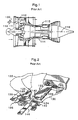
- Fig. 1 is a schematic view illustrating a turbofan engine 110 for an airplane.
- the engine 110 includes a fan assembly 112 which is coaxially disposed with respect to a center shaft 116 and is driven by a core engine 114. During the operation of the engine 110, external air 118 is sucked by the fan assembly 112 so as to produce a thrust for enabling an airplane to fly.
- a comparatively large bird 120 may be sucked into the fan assembly 112.
- the bird 120 impacts on fan blades 122 extending outward from a rotor disk 124 in a radial direction, so that a part of the fan blades 122 is broken and scattered. Additionally, alien materials except for the bird may be sucked into the fan assembly to thereby damage components.
- the fan blades 122 or a part thereof may be broken and scattered due to a large load or the like.
- FBO Fluor Off
- a part of the fan blades 122 may be scattered to collide against the adjacent other fan blades 122, so that an axial forward (upstream) shock power acts on the fan blades 122.
- the fan assembly 112 needs to be provided with a structure capable of retaining the fan blades 122 in the rotor disk 124 even when the axial forward shock power acts on the fan blades 122.
- Patent Document 1 has already proposed a fan blade retainer for satisfying the above-described requirements.
- Patent Document 1 discloses a retainer assembly 126 for retaining the fan blades 122 in the rotor disk 124. As shown in Fig. 2 , the retainer assembly 126 includes the rotor disk 124, a first blade retainer 138, and a second blade retainer 144.
- the rotor disk 124 includes a plurality of dovetail posts 128 which are spaced at a predetermined angular interval in a circumferential direction, and a dovetail groove 130 is formed therebetween.
- Each fan blade 122 includes a dovetail 132 fitted to the dovetail groove 130 in an axial direction, and the dovetail 132 is immovably retained in a radial direction by the dovetail post 128.
- the first blade retainer 138 is provided so as to prevent the fan blade 122 from moving in an axial forward direction (upstream direction).
- the first blade retainer 138 includes a fixed plate 140 fixed to the rotor disk 124 so as to immovably retain the fan blade 122 in the dovetail groove 130 in an axial direction.
- the fixed plate 140 is inserted in an outward radial direction into a pair of grooves 142 formed in the adjacent dovetail posts 128.
- the second blade retainer 144 is provided so as to prevent the axial movement of the fan blades 122 by serving as a chock after the fan blades 122 move by a predetermined distance in a case where the axial movement of the fan blades 122 cannot be prevented by the first blade retainer 138.
- both the first blade retainer 138 and the second blade retainer 144 disperse the axial forward shock energy acting on the fan blades 122 so that each fan blade 122 is retained in the dovetail grooves 130.
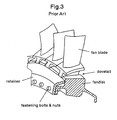
- Fig. 3 is a schematic view illustrating a dovetail structure according to a conventional art.
- a fan disk or a spinner a circular disk
- a conventional dovetail structure in which a dovetail part is formed in a root portion of the fan blade so as to extend in a longitudinal direction and the dovetail part is fitted to a dovetail groove formed in the periphery of a disk.
- a member called a retainer was fastened to a front portion of the blade by fastening bolts, nuts, and the like.
- Examples of the retainer include a circular-ring type for functioning with respect to a plurality of blades and a plate type for functioning with respect to each of the blades.
- an object of the invention is to provide a fan blade retaining structure capable of surely preventing a fan blade from coming off from a disk even when an axial forward load acts on the fan blade upon breaking the fan blade, of being easily designed with high estimation precision of stress, and of enabling a fastening bolt to be lighter in weight, smaller in size, and fewer in number than a conventional fastening bolt, thereby reducing the number of components. Accordingly, it is possible to provide the fan blade retaining structure capable of realizing a decrease in weight and cost.
- a fan blade retaining structure in which a plurality of fan blades is configured to be attached to an outer periphery of a disk rotationally driven by a turbine, wherein the disk includes a plurality of dovetail grooves configured to be spaced at a predetermined angular interval in a circumferential direction and to extend in an axial direction, wherein each of the fan blades includes a dovetail part configured to be fitted to each of the dovetail grooves in an axial direction and capable of transmitting a centrifugal force produced during rotation to the disk, wherein the disk further includes a flange part configured to be positioned in front of the dovetail grooves and to extend outward in a radial direction, and wherein the fan blade retaining structure further includes a ring-shape retainer member configured to be fitted between a front surface of the dovetail part and a rear surface of the flange part so as to transmit an axial forward load acting on the fan blade to the disk via the rear surface of
- the flange part of the disk includes disk tooth parts configured to be spaced at a predetermined angular interval in a circumferential direction and to project outward in a radial direction.
- the retainer member includes a ring part configured to have a rear surface coming into contact with the front surface of the dovetail part and retainer tooth parts configured to be formed inside the ring part so as to be spaced at a predetermined angular interval in a circumferential direction and to project inward in a radial direction.
- Each of the retainer tooth parts is capable of passing between the adjacent disk tooth parts in an axial direction and comes close to the rear surface of the disk tooth part to overlap therewith at the same position in a circumferential direction.
- the fan blade retaining structure further preferably includes a fastener configured to fix the retainer tooth part to the disk tooth part in a state where the retainer tooth part comes close to the disk tooth part to overlap with each other.
- the disk tooth part is formed at the same position as that of the dovetail groove in a circumferential direction.
- the retainer member is provided so as to be fitted between the front surface of the dovetail part and the rear surface of the flange part, even when the axial forward load acts on the fan blades upon breaking the fan blades, it is possible to transmit the axial forward load from the front surface of the dovetail part to the disk via the rear surface of the flange part and the retainer member.
- a stress occurring in the retainer member by the axial forward load mainly corresponds to an axial compressive stress and a stress occurring in the flange part by the axial forward load mainly corresponds to an axial stretching stress, it is possible to accurately estimate an internal stress occurring in the retainer member and the flange part in accordance with the axial forward load.
- the ring-shape retainer member Since the ring-shape retainer member is used, it is possible to reduce the number of components.
- the axial forward load does not act on the fastener (bolt, nut, and the like) for fastening the retainer member to the flange part by transmitting the axial forward load to the retainer member and the flange part, it is possible to more reduce the weight, the size, and the number of the fastening bolt than a conventional fastening bolt, and thus to reduce the number of components. Accordingly, it is possible to realize a decrease in weight and cost.
- the flange part includes the disk tooth parts which project outward in a radial direction and the retainer member includes the ring part which comes into contact with the front surfaces of the dovetail parts and the retainer tooth parts which project inward in a radial direction.
- each of the retainer tooth parts can pass between the adjacent disk tooth parts in an axial direction and is disposed adjacent to each rear surface of the disk tooth parts.
- the retainer member can be easily fitted between the front surface of the dovetail parts and the rear surface of the flange part in such a manner that the retainer tooth parts of the retainer member pass between the adjacent disk tooth parts in an axial direction and are rotated up to the same positions in a circumferential direction so as to be adjacent to the rear surfaces of the disk tooth part.
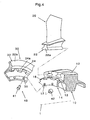
- Fig. 4 is an overall perspective view illustrating a state where a fan blade retaining structure, not in accordance with the present invention but provided so as to enable a greater understanding thereof, is disassembled.
- the fan blade retaining structure is configured such that a plurality of fan blades 20 are attached to the outer periphery of a disk 10 which is rotationally driven by a turbine (not shown).
- the fan blade retaining structure includes the disk 10, the fan blades 20, a retainer member 30, and a fastener 40.
- the disk 10 includes a plurality of dovetail grooves 12 which are spaced at a predetermined angular interval in a circumferential direction and extends in an axial direction. Although it is desirable that the number of the dovetail grooves 12 is the same as that of the fan blades 20, a plurality (two or more) of fan blades 20 may be attached to one dovetail groove 12.
- the dovetail grooves 12 are parallel to a shaft center 1 of a rotary shaft, but may be inclined with respect to the shaft center 1.
- each of the dovetail grooves 12 may be formed into a linear shape or a circular arc shape so long as each of the fan blades 20 is inserted and fitted in an axial direction from the front side.
- the fan blade 20 includes a dovetail part 22 which is formed in the inner end in a radial direction so as to be fitted to the dovetail groove 12.
- the dovetail part 22 is configured to be fitted to the dovetail groove 12 in an axial direction from the front side and to transmit a centrifugal force acting on the fan blade 20 produced during rotation to the disk 10.
- Fig. 5A is a transverse sectional view illustrating a fan part of an engine provided with the fan blade retaining structure, in which only the upper side of the shaft center 1 of the rotary shaft is shown.
- Fig. 5B is an enlarged view illustrating a B part shown in Fig. 5A .
- Reference numeral 1 denotes the shaft center of the rotary shaft of the disk 10 and the fan blade 20
- Reference numeral 2 denotes an air flow passage
- Reference numeral 3 denotes the inner peripheral surface of the air flow passage
- Reference numeral 4 denotes an intake air flow
- Reference numeral 5 denotes an axial forward power acting on the fan blade 20 in the event of FBO.
- the disk 10 further includes a flange part 14 which is positioned in front of the dovetail groove 12 and extends in a radial outer direction.
- the flange part 14 is integrally connected to a hollow cylindrical part 13 which extends forward from the inner end of the disk 10.
- the flange part 14 further includes disk tooth parts 16 which are spaced at a predetermined angular interval in a circumferential direction and project outward in a radial direction.
- the retainer member 30 includes a hollow disk-shape ring part 32 and retainer tooth parts 34 which are integrally formed with the inner portion of the ring part 32.
- the ring part 32 includes a rear surface 32a, and the rear surface 32a comes into contact with a front surface 22a of the dovetail part 22 inserted into the dovetail groove 12.
- retainer tooth parts 34 are spaced at a predetermined angular interval in a circumferential direction and project inward in a radial direction.
- the disk tooth parts 16 are formed at centers in a circumferential direction of the dovetail grooves 12 which are adjacent to each other in a circumferential direction and are not positioned on extension lines of the dovetail grooves 12. Accordingly, in this example, the retainer tooth parts 34 are formed in a circumferential direction so as to have the same pitches as those of the dovetail grooves 12 and have the same number as that of the dovetail grooves 12.
- the disk tooth parts 16 can be formed at the radial positions so as to have the substantially same heights as those of the dovetail parts 22, and the forward axial load produced from the dovetail parts 22 can be surely supported by two disk tooth parts 16 in a circumferential direction.
- the disk tooth parts are formed at the same positions as those of the dovetail grooves in a circumferential direction.
- the disk tooth parts 16 need to be formed at the radial positions lower than the bottom portions of the dovetail parts 22 so as not to be positioned on the extension lines of the dovetail grooves 12, the axial forward load produced from the dovetail parts 22 can be surely supported by the disk tooth parts 16 disposed at the same positions in a circumferential direction.
- the number of the disk tooth parts 16 and the retainer tooth parts 34 needs not to be the same as that of the dovetail grooves 12, but the number may be two or more (for example, four, eight, sixteen or the like) so long as a balance is ensured during a high-speed rotation.
- Fig. 6A is a view taken along the line C-C shown in Fig. 5B in a state where the retainer member is being mounted.
- Fig. 6B is a view taken along the line C-C shown in Fig. 5B in a state where the retainer member is completely mounted.
- an axial distance (thickness) from the rear surface 32a of the retainer member 30 to each front surface 34a of the retainer tooth parts 34 is set to be a smaller value than an axial distance from the front surface 22a of the dovetail part 22 to each rear surface 16a of the disk tooth parts 16 in a mounting state. It is desirable that the gap is set so that the retainer member 30 smoothly rotates about the shaft center 1 in a state where the retainer member is mounted.
- each of the retainer tooth parts 34 can pass between the adjacent disk tooth parts 16 in an axial direction.
- the retainer tooth parts come close to the rear surfaces of the disk tooth parts 16 to overlap therewith at the same positions in a circumferential direction by rotating the retainer member 30 about the shaft center 1 by a predetermined angle (in this example, 30 degree or so). It is desirable that the close gap therebetween is set to be small so long as the retainer tooth parts do not interfere with the disk tooth parts within an operation temperature range of the engine.
- the fastener 40 includes a bolt 41 and a nut 42 which are screw-connected to each other while passing through a through hole 35 formed in the retainer member 30 and a through hole 17 formed in the flange part 14 of the disk 10 so as to fix the retainer tooth parts 34 and the disk tooth parts 16 at the same positions in a circumferential direction.
- the flange part 14 extends inward in a radial direction, and the through hole 17 is formed in the extending portion.
- An inverse L-shape portion is formed in the retainer member 30 so as to come into contact with the extending portion, and the through hole 35 is formed in the inverse L-shape portion.
- the invention is not limited to this configuration, but may be configured such that the retainer member 30 is formed into, for example, a ring-shape flat plate instead of the inverse L-shape portion and the ring-shape flat plate is directly fixed to the disk 10.
- the retainer tooth parts 34 and the disk tooth parts 16 are fixed at the same positions in a circumferential direction during the time when the ring-shape retainer member 30 shown in Fig. 6B is completely mounted and the engine is operated.
- the retainer member 30 can transmit the axial forward load acting on the fan blade 20 to the disk 10 via the rear surfaces 16a of the disk tooth parts 16 while being fitted between the front surfaces 22a of the dovetail parts 22 and the rear surfaces 16a of the disk tooth parts 16.
- a stress occurring in the retainer member 30 by the axial forward load mainly corresponds to an axial compressive stress and a stress occurring in the flange part 14 by the axial forward load mainly corresponds to an axial stretching stress, it is possible to accurately estimate an internal stress occurring in the retainer member 30 and the flange part 14 in accordance with the axial forward load.
- the axial forward load does not act on the fastener 40 (bolt, nut, and the like) for fastening the retainer member 30 to the flange part 14 by transmitting the axial forward load to the retainer member 30 and the flange part 14, it is possible to more reduce the weight, the size, and the number of the fastener 40 than a conventional fastener, and thus to reduce the number of components.
- the flange part 14 of the disk 10 includes the disk tooth parts 16 which project outward in a radial direction and the retainer member 30 includes the ring part 32 which comes into contact with the front surfaces 22a of the dovetail parts 22 and the retainer tooth parts 34 which project inward in a radial direction.
- each of the retainer tooth parts 34 can pass between the adjacent disk tooth parts 16 in an axial direction and is disposed adjacent to each rear surface 16a of the disk tooth parts 16.
- the retainer member 30 can be easily fitted between the font surface 22a and the rear surface 16a of the flange part in such a manner that the retainer tooth parts 34 of the retainer member 30 pass between the adjacent disk tooth parts 16 in an axial direction and are rotated up to the same positions in a circumferential direction so as to be adjacent to the rear surfaces of the disk tooth part 16.
Landscapes
- Engineering & Computer Science (AREA)
- Mechanical Engineering (AREA)
- General Engineering & Computer Science (AREA)
- Structures Of Non-Positive Displacement Pumps (AREA)
- Turbine Rotor Nozzle Sealing (AREA)
Description
- The present invention relates to a fan blade retaining structure for preventing a fan blade from coming off from a disk even when an axial forward load acts on the fan blade upon breaking the fan blade. A fan blade retaining structure according to the preamble of
claim 1 is known fromGB 2 286 431 A -
Fig. 1 is a schematic view illustrating aturbofan engine 110 for an airplane. Theengine 110 includes afan assembly 112 which is coaxially disposed with respect to acenter shaft 116 and is driven by acore engine 114. During the operation of theengine 110,external air 118 is sucked by thefan assembly 112 so as to produce a thrust for enabling an airplane to fly. - When the airplane having the above-described
engine 110 takes off or lands, for example, a comparativelylarge bird 120 may be sucked into thefan assembly 112. In this case, thebird 120 impacts onfan blades 122 extending outward from arotor disk 124 in a radial direction, so that a part of thefan blades 122 is broken and scattered. Additionally, alien materials except for the bird may be sucked into the fan assembly to thereby damage components. In addition to the supposition, thefan blades 122 or a part thereof may be broken and scattered due to a large load or the like. Hereinafter, such a phenomenon will be referred to as FBO (Fan Blade Off). - In the event of the FBO, a part of the
fan blades 122 may be scattered to collide against the adjacentother fan blades 122, so that an axial forward (upstream) shock power acts on thefan blades 122. - Since the axial forward shock power acting on the
fan blades 122 acts in a direction in which thefan blades 122 come off from therotor disk 124, thefan assembly 112 needs to be provided with a structure capable of retaining thefan blades 122 in therotor disk 124 even when the axial forward shock power acts on thefan blades 122. -
Patent Document 1 has already proposed a fan blade retainer for satisfying the above-described requirements. -
Patent Document 1 discloses aretainer assembly 126 for retaining thefan blades 122 in therotor disk 124. As shown inFig. 2 , theretainer assembly 126 includes therotor disk 124, afirst blade retainer 138, and asecond blade retainer 144. - The
rotor disk 124 includes a plurality ofdovetail posts 128 which are spaced at a predetermined angular interval in a circumferential direction, and adovetail groove 130 is formed therebetween. Eachfan blade 122 includes adovetail 132 fitted to thedovetail groove 130 in an axial direction, and thedovetail 132 is immovably retained in a radial direction by thedovetail post 128. With the above-described configuration, a centrifugal force produced during rotation of thefan blades 122 is transmitted to therotor disk 124 via thedovetail post 128. - The
first blade retainer 138 is provided so as to prevent thefan blade 122 from moving in an axial forward direction (upstream direction). Thefirst blade retainer 138 includes afixed plate 140 fixed to therotor disk 124 so as to immovably retain thefan blade 122 in thedovetail groove 130 in an axial direction. Thefixed plate 140 is inserted in an outward radial direction into a pair ofgrooves 142 formed in theadjacent dovetail posts 128. - The
second blade retainer 144 is provided so as to prevent the axial movement of thefan blades 122 by serving as a chock after thefan blades 122 move by a predetermined distance in a case where the axial movement of thefan blades 122 cannot be prevented by thefirst blade retainer 138. With the above-described configuration, both thefirst blade retainer 138 and thesecond blade retainer 144 disperse the axial forward shock energy acting on thefan blades 122 so that eachfan blade 122 is retained in thedovetail grooves 130. -
US Patent No. 5,282,720 'Fan blade retainer' -
Fig. 3 is a schematic view illustrating a dovetail structure according to a conventional art. As shown in the drawing, it is necessary to attach the fan blades of the turbofan engine to a peripheral portion of a circular disk (called a fan disk or a spinner) rotationally driven by a turbine. For this reason, in the past, there was adopted a conventional dovetail structure in which a dovetail part is formed in a root portion of the fan blade so as to extend in a longitudinal direction and the dovetail part is fitted to a dovetail groove formed in the periphery of a disk. - In addition, in order to prevent the fan blade from coming off from the dovetail groove due to the axial forward power, in the past, a member called a retainer was fastened to a front portion of the blade by fastening bolts, nuts, and the like.
- Examples of the retainer include a circular-ring type for functioning with respect to a plurality of blades and a plate type for functioning with respect to each of the blades.
- However, in case of the circular-ring type retainer, since a gap between an action portion of a load and a fastening portion such as a bolt and a nut is long, a problem arises in that the stress acting on the bolt due to the load is difficult to be estimated and the retainer is difficult to be designed. Meanwhile, in case of the plate type retainer, since the retainer is mounted to each blade, a problem arises in that operability is poor. For this reason, in both cases of the circular-ring type retainer and the plate type retainer, a problem arises in that a decrease in weight is difficult to be achieved and a cost is high.
- In addition, in case of the retainer assembly described in
Patent Document 1, although both thefirst blade retainer 138 and thesecond blade retainer 144 can disperse the axial forward shock energy acting on thefan blades 122 so that eachfan blade 122 is retained in thedovetail groove 130, a problem arises in that the structure is complex and a manufacturing cost is high. - In the retainer assembly, since it is necessary to provide a plurality of
first blade retainers 138 and thesecond blade retainers 144, a problem arises in that the operability during an assembling operation is poor. - The present invention is contrived in consideration of the above-described problems. That is, an object of the invention is to provide a fan blade retaining structure capable of surely preventing a fan blade from coming off from a disk even when an axial forward load acts on the fan blade upon breaking the fan blade, of being easily designed with high estimation precision of stress, and of enabling a fastening bolt to be lighter in weight, smaller in size, and fewer in number than a conventional fastening bolt, thereby reducing the number of components. Accordingly, it is possible to provide the fan blade retaining structure capable of realizing a decrease in weight and cost.
- According to the invention, there is provided a fan blade retaining structure in which a plurality of fan blades is configured to be attached to an outer periphery of a disk rotationally driven by a turbine, wherein the disk includes a plurality of dovetail grooves configured to be spaced at a predetermined angular interval in a circumferential direction and to extend in an axial direction, wherein each of the fan blades includes a dovetail part configured to be fitted to each of the dovetail grooves in an axial direction and capable of transmitting a centrifugal force produced during rotation to the disk, wherein the disk further includes a flange part configured to be positioned in front of the dovetail grooves and to extend outward in a radial direction, and wherein the fan blade retaining structure further includes a ring-shape retainer member configured to be fitted between a front surface of the dovetail part and a rear surface of the flange part so as to transmit an axial forward load acting on the fan blade to the disk via the rear surface of the flange part.
- According to the invention, the flange part of the disk includes disk tooth parts configured to be spaced at a predetermined angular interval in a circumferential direction and to project outward in a radial direction.
- The retainer member includes a ring part configured to have a rear surface coming into contact with the front surface of the dovetail part and retainer tooth parts configured to be formed inside the ring part so as to be spaced at a predetermined angular interval in a circumferential direction and to project inward in a radial direction.
- Each of the retainer tooth parts is capable of passing between the adjacent disk tooth parts in an axial direction and comes close to the rear surface of the disk tooth part to overlap therewith at the same position in a circumferential direction.
- The fan blade retaining structure further preferably includes a fastener configured to fix the retainer tooth part to the disk tooth part in a state where the retainer tooth part comes close to the disk tooth part to overlap with each other.
- The disk tooth part is formed at the same position as that of the dovetail groove in a circumferential direction.
- According to the configuration of the invention, since the retainer member is provided so as to be fitted between the front surface of the dovetail part and the rear surface of the flange part, even when the axial forward load acts on the fan blades upon breaking the fan blades, it is possible to transmit the axial forward load from the front surface of the dovetail part to the disk via the rear surface of the flange part and the retainer member.
- Since a stress occurring in the retainer member by the axial forward load mainly corresponds to an axial compressive stress and a stress occurring in the flange part by the axial forward load mainly corresponds to an axial stretching stress, it is possible to accurately estimate an internal stress occurring in the retainer member and the flange part in accordance with the axial forward load.
- Since the retainer member and the flange part are prevented from being broken by setting the internal stress to a sufficiently small stress, it is possible to surely prevent the fan blade from coming off from the disk.
- Since the ring-shape retainer member is used, it is possible to reduce the number of components.
- Since the axial forward load does not act on the fastener (bolt, nut, and the like) for fastening the retainer member to the flange part by transmitting the axial forward load to the retainer member and the flange part, it is possible to more reduce the weight, the size, and the number of the fastening bolt than a conventional fastening bolt, and thus to reduce the number of components. Accordingly, it is possible to realize a decrease in weight and cost.
- In addition, the flange part includes the disk tooth parts which project outward in a radial direction and the retainer member includes the ring part which comes into contact with the front surfaces of the dovetail parts and the retainer tooth parts which project inward in a radial direction. Also, each of the retainer tooth parts can pass between the adjacent disk tooth parts in an axial direction and is disposed adjacent to each rear surface of the disk tooth parts.
- Accordingly, the retainer member can be easily fitted between the front surface of the dovetail parts and the rear surface of the flange part in such a manner that the retainer tooth parts of the retainer member pass between the adjacent disk tooth parts in an axial direction and are rotated up to the same positions in a circumferential direction so as to be adjacent to the rear surfaces of the disk tooth part.
- Since the axial forward load does not act on the fastener by fixing the retainer tooth parts to the disk tooth parts at the same positions in a circumferential direction by using the fastener (bolt, nut, and the like), it is possible to more reduce the weight, the size, and the number of the fastener than the conventional fastener, and thus to reduce the number of components.
-
-
Fig. 1 is a schematic view illustrating a turbofan engine for an airplane. -
Fig. 2 is a configuration view illustrating a fan blade retainer disclosed inPatent Document 1. -
Fig. 3 is a schematic view illustrating a dovetail structure according to a conventional art. -
Fig. 4 is an overall perspective view illustrating a state where a fan blade retaining structure, not in accordance with the present invention but provided so as to enable a greater understanding thereof, is disassembled. -
Fig. 5A is a transverse sectional view illustrating an engine provided with the fan blade retaining structure, not in accordance with the present invention but provided so as to enable a greater understanding thereof. -
Fig. 5B is an enlarged view illustrating a B part shown inFig. 5A . -
Fig. 6A is a view taken along the line C-C shown inFig. 5B in a state where a retainer member is being mounted. -
Fig. 6B is a view taken along the line C-C shown inFig. 5B in a state where the retainer member is completely mounted. - Hereinafter, a fan blade retaining structure not in accordance with the present invention but provided so as to enable a greater understanding thereof will be described in detail with reference to the accompanying drawings. In addition, in the respective drawings, the same reference numerals are given to the same components and the repetitive description thereof will be omitted.
-
Fig. 4 is an overall perspective view illustrating a state where a fan blade retaining structure, not in accordance with the present invention but provided so as to enable a greater understanding thereof, is disassembled. The fan blade retaining structure is configured such that a plurality offan blades 20 are attached to the outer periphery of adisk 10 which is rotationally driven by a turbine (not shown). - As shown in the drawing, the fan blade retaining structure includes the
disk 10, thefan blades 20, aretainer member 30, and afastener 40. - The
disk 10 includes a plurality ofdovetail grooves 12 which are spaced at a predetermined angular interval in a circumferential direction and extends in an axial direction. Although it is desirable that the number of thedovetail grooves 12 is the same as that of thefan blades 20, a plurality (two or more) offan blades 20 may be attached to onedovetail groove 12. - In this example, the
dovetail grooves 12 are parallel to ashaft center 1 of a rotary shaft, but may be inclined with respect to theshaft center 1. In addition, each of thedovetail grooves 12 may be formed into a linear shape or a circular arc shape so long as each of thefan blades 20 is inserted and fitted in an axial direction from the front side. - The
fan blade 20 includes adovetail part 22 which is formed in the inner end in a radial direction so as to be fitted to thedovetail groove 12. Thedovetail part 22 is configured to be fitted to thedovetail groove 12 in an axial direction from the front side and to transmit a centrifugal force acting on thefan blade 20 produced during rotation to thedisk 10. -
Fig. 5A is a transverse sectional view illustrating a fan part of an engine provided with the fan blade retaining structure, in which only the upper side of theshaft center 1 of the rotary shaft is shown.Fig. 5B is an enlarged view illustrating a B part shown inFig. 5A . - In addition, in the drawing,
Reference numeral 1 denotes the shaft center of the rotary shaft of thedisk 10 and thefan blade 20,Reference numeral 2 denotes an air flow passage,Reference numeral 3 denotes the inner peripheral surface of the air flow passage,Reference numeral 4 denotes an intake air flow, andReference numeral 5 denotes an axial forward power acting on thefan blade 20 in the event of FBO. - As shown in
Figs. 4 ,5A, and 5B , thedisk 10 further includes aflange part 14 which is positioned in front of thedovetail groove 12 and extends in a radial outer direction. Theflange part 14 is integrally connected to a hollowcylindrical part 13 which extends forward from the inner end of thedisk 10. - The
flange part 14 further includesdisk tooth parts 16 which are spaced at a predetermined angular interval in a circumferential direction and project outward in a radial direction. - The
retainer member 30 includes a hollow disk-shape ring part 32 andretainer tooth parts 34 which are integrally formed with the inner portion of thering part 32. - The
ring part 32 includes arear surface 32a, and therear surface 32a comes into contact with afront surface 22a of thedovetail part 22 inserted into thedovetail groove 12. - In addition, the
retainer tooth parts 34 are spaced at a predetermined angular interval in a circumferential direction and project inward in a radial direction. - As shown in
Fig. 4 , in this example, thedisk tooth parts 16 are formed at centers in a circumferential direction of thedovetail grooves 12 which are adjacent to each other in a circumferential direction and are not positioned on extension lines of thedovetail grooves 12. Accordingly, in this example, theretainer tooth parts 34 are formed in a circumferential direction so as to have the same pitches as those of thedovetail grooves 12 and have the same number as that of thedovetail grooves 12. - With the above-described configuration, the
disk tooth parts 16 can be formed at the radial positions so as to have the substantially same heights as those of thedovetail parts 22, and the forward axial load produced from thedovetail parts 22 can be surely supported by twodisk tooth parts 16 in a circumferential direction. - In contrast, in the embodiment of the invention, the disk tooth parts are formed at the same positions as those of the dovetail grooves in a circumferential direction.
- In this case, although the
disk tooth parts 16 need to be formed at the radial positions lower than the bottom portions of thedovetail parts 22 so as not to be positioned on the extension lines of thedovetail grooves 12, the axial forward load produced from thedovetail parts 22 can be surely supported by thedisk tooth parts 16 disposed at the same positions in a circumferential direction. - In addition, the number of the
disk tooth parts 16 and theretainer tooth parts 34 needs not to be the same as that of thedovetail grooves 12, but the number may be two or more (for example, four, eight, sixteen or the like) so long as a balance is ensured during a high-speed rotation. -
Fig. 6A is a view taken along the line C-C shown inFig. 5B in a state where the retainer member is being mounted.Fig. 6B is a view taken along the line C-C shown inFig. 5B in a state where the retainer member is completely mounted. - In
Figs. 4 to 6A and6B , an axial distance (thickness) from therear surface 32a of theretainer member 30 to eachfront surface 34a of theretainer tooth parts 34 is set to be a smaller value than an axial distance from thefront surface 22a of thedovetail part 22 to each rear surface 16a of thedisk tooth parts 16 in a mounting state. It is desirable that the gap is set so that theretainer member 30 smoothly rotates about theshaft center 1 in a state where the retainer member is mounted. - As shown in
Fig. 6A , each of theretainer tooth parts 34 can pass between the adjacentdisk tooth parts 16 in an axial direction. In addition, as shown inFig. 6B , the retainer tooth parts come close to the rear surfaces of thedisk tooth parts 16 to overlap therewith at the same positions in a circumferential direction by rotating theretainer member 30 about theshaft center 1 by a predetermined angle (in this example, 30 degree or so). It is desirable that the close gap therebetween is set to be small so long as the retainer tooth parts do not interfere with the disk tooth parts within an operation temperature range of the engine. - In
Figs. 4 ,5A, and 5B , thefastener 40 includes abolt 41 and anut 42 which are screw-connected to each other while passing through a throughhole 35 formed in theretainer member 30 and a throughhole 17 formed in theflange part 14 of thedisk 10 so as to fix theretainer tooth parts 34 and thedisk tooth parts 16 at the same positions in a circumferential direction. - In addition, in this example, the
flange part 14 extends inward in a radial direction, and the throughhole 17 is formed in the extending portion. An inverse L-shape portion is formed in theretainer member 30 so as to come into contact with the extending portion, and the throughhole 35 is formed in the inverse L-shape portion. - However, the invention is not limited to this configuration, but may be configured such that the
retainer member 30 is formed into, for example, a ring-shape flat plate instead of the inverse L-shape portion and the ring-shape flat plate is directly fixed to thedisk 10. - With the above-described configuration, the
retainer tooth parts 34 and thedisk tooth parts 16 are fixed at the same positions in a circumferential direction during the time when the ring-shape retainer member 30 shown inFig. 6B is completely mounted and the engine is operated. - In addition, the
retainer member 30 can transmit the axial forward load acting on thefan blade 20 to thedisk 10 via the rear surfaces 16a of thedisk tooth parts 16 while being fitted between thefront surfaces 22a of thedovetail parts 22 and the rear surfaces 16a of thedisk tooth parts 16. - With the above-described configuration, since there is provided the
retainer member 30 fitted between thefront surfaces 22a of thedovetail parts 22 and the rear surfaces 16a of the flange part 14 (the disk tooth parts 16), even when the axial forward load occurs acts on the fan blade upon breaking thefan blade 20, the axial forward load can be transmitted from thefront surfaces 22a of thedovetail parts 22 to thedisk 10 via theretainer member 30 and the rear surfaces 16a of the flange part. - Since a stress occurring in the
retainer member 30 by the axial forward load mainly corresponds to an axial compressive stress and a stress occurring in theflange part 14 by the axial forward load mainly corresponds to an axial stretching stress, it is possible to accurately estimate an internal stress occurring in theretainer member 30 and theflange part 14 in accordance with the axial forward load. - Since the
retainer member 30 and theflange part 14 are prevented from being broken by setting the internal stress to a sufficiently small stress, it is possible to surely prevent thefan blade 20 from coming off from thedisk 10. - Since the ring-
shape retainer member 30 is used, it is possible to reduce the number of components. - Since the axial forward load does not act on the fastener 40 (bolt, nut, and the like) for fastening the
retainer member 30 to theflange part 14 by transmitting the axial forward load to theretainer member 30 and theflange part 14, it is possible to more reduce the weight, the size, and the number of thefastener 40 than a conventional fastener, and thus to reduce the number of components. - In addition, the
flange part 14 of thedisk 10 includes thedisk tooth parts 16 which project outward in a radial direction and theretainer member 30 includes thering part 32 which comes into contact with thefront surfaces 22a of thedovetail parts 22 and theretainer tooth parts 34 which project inward in a radial direction. Also, each of theretainer tooth parts 34 can pass between the adjacentdisk tooth parts 16 in an axial direction and is disposed adjacent to each rear surface 16a of thedisk tooth parts 16. Accordingly, theretainer member 30 can be easily fitted between thefont surface 22a and the rear surface 16a of the flange part in such a manner that theretainer tooth parts 34 of theretainer member 30 pass between the adjacentdisk tooth parts 16 in an axial direction and are rotated up to the same positions in a circumferential direction so as to be adjacent to the rear surfaces of thedisk tooth part 16. - Since the axial forward load does not act on the
fastener 40 by fixing theretainer tooth parts 34 to thedisk tooth parts 16 at the same positions in a circumferential direction by using the fastener 40 (bolt, nut, and the like), it is possible to more reduce the weight, the size, and the number of the fastener than the conventional fastener, and thus to reduce the number of components.
Claims (2)
- A fan blade retaining structure in which a plurality of fan blades (20) is configured to be attached to an outer periphery of a disk (10) rotationally driven by a turbine,
wherein the disk (10) includes a plurality of dovetail grooves (12) configured to be spaced at a predetermined angular interval in a circumferential direction and to extend in an axial direction,
wherein each of the fan blades(20) includes a dovetail part (22) configured to be fitted to each of the dovetail grooves (12) in an axial direction and capable of transmitting a centrifugal force produced during rotation to the disk (10),
wherein the disk (10) includes a flange part (14) configured to be positioned in front of the dovetail grooves (12) and to extend outward in a radial direction,
wherein the fan blade retaining structure further comprises a ring-shape retainer member (30) configured to be fitted between a front surface (22a) of the dovetail part (22) and a rear surface (16a) of the flange part (14) so as to transmit an axial forward load acting on the fan blade to the disk (10) via the rear surface (16a) of the flange part (14),
wherein the flange part (14) of the disk (10) includes disk tooth parts (16) configured to be spaced at a predetermined angular interval in a circumferential direction and to project outward in a radial direction,
wherein the retainer member (30) includes a ring part (32) configured to have a rear surface (16a) coming into contact with the front surface (22a) of the dovetail part (22) and retainer tooth parts (34) configured to be formed inside the ring part (32) so as to be spaced at a predetermined angular interval in a circumferential direction and to project inward in a radial direction, and
wherein each of the retainer tooth parts (34) is capable of passing between the adjacent disk tooth parts (16) in an axial direction and comes close to the rear surface (16a) of the disk tooth part (16) to overlap therewith at the same position in a circumferential direction
characterized in that
the disk tooth part (16) is formed at the same position as that of the dovetail groove in (12) a circumferential direction. - The fan blade retaining structure according to Claim 1, further comprising:a fastener (40) configured to fix the retainer tooth part to the disk tooth part (16) in a state where the retainer tooth part (34) comes close to the disk tooth part (16) to overlap with each other.
Applications Claiming Priority (2)
| Application Number | Priority Date | Filing Date | Title |
|---|---|---|---|
| JP2006067620A JP2007247406A (en) | 2006-03-13 | 2006-03-13 | Holding structure of fan blade |
| PCT/JP2007/054871 WO2007105701A1 (en) | 2006-03-13 | 2007-03-13 | Holding structure of fan blade |
Publications (3)
| Publication Number | Publication Date |
|---|---|
| EP1995467A1 EP1995467A1 (en) | 2008-11-26 |
| EP1995467A4 EP1995467A4 (en) | 2013-01-02 |
| EP1995467B1 true EP1995467B1 (en) | 2014-05-07 |
Family
ID=38509521
Family Applications (1)
| Application Number | Title | Priority Date | Filing Date |
|---|---|---|---|
| EP07738343.8A Active EP1995467B1 (en) | 2006-03-13 | 2007-03-13 | Holding structure of fan blade |
Country Status (5)
| Country | Link |
|---|---|
| US (1) | US20090022593A1 (en) |
| EP (1) | EP1995467B1 (en) |
| JP (1) | JP2007247406A (en) |
| CA (1) | CA2637277C (en) |
| WO (1) | WO2007105701A1 (en) |
Families Citing this family (20)
| Publication number | Priority date | Publication date | Assignee | Title |
|---|---|---|---|---|
| FR2955889B1 (en) * | 2010-01-29 | 2012-11-16 | Snecma | MEANS FOR LOCKING A SEALING FLASK ON A TURBINE DISK |
| FR2955904B1 (en) * | 2010-02-04 | 2012-07-20 | Snecma | TURBOMACHINE BLOWER |
| FR2959527B1 (en) | 2010-04-28 | 2012-07-20 | Snecma | ANTI-WEAR PIECE FOR TURBOREACTOR BLOWER BLADE DRAFT |
| FR2963806B1 (en) * | 2010-08-10 | 2013-05-03 | Snecma | DEVICE FOR LOCKING A FOOT OF A ROTOR BLADE |
| US8840375B2 (en) * | 2011-03-21 | 2014-09-23 | United Technologies Corporation | Component lock for a gas turbine engine |
| FR2974863B1 (en) * | 2011-05-06 | 2015-10-23 | Snecma | TURBOMACHINE BLOWER DISK |
| US9376926B2 (en) * | 2012-11-15 | 2016-06-28 | United Technologies Corporation | Gas turbine engine fan blade lock assembly |
| FR3014151B1 (en) * | 2013-11-29 | 2015-12-04 | Snecma | BLOWER, ESPECIALLY FOR A TURBOMACHINE |
| US9624775B2 (en) | 2014-05-30 | 2017-04-18 | Rolls-Royce Plc | Developments in or relating to rotor balancing |
| EP2792849B1 (en) * | 2014-05-30 | 2016-07-13 | Rolls-Royce plc | Developments in or relating to rotor balancing |
| MY191339A (en) * | 2014-08-19 | 2022-06-16 | Nuctech Co Ltd | Apparatus and method for inspecting moving target |
| KR102182102B1 (en) * | 2014-11-27 | 2020-11-23 | 한화에어로스페이스 주식회사 | A turbine apparatus |
| CN105114349B (en) * | 2015-08-17 | 2018-04-24 | 南方中金环境股份有限公司 | A kind of centrifugal pump movable flange structure |
| US10323519B2 (en) * | 2016-06-23 | 2019-06-18 | United Technologies Corporation | Gas turbine engine having a turbine rotor with torque transfer and balance features |
| US10344622B2 (en) | 2016-07-22 | 2019-07-09 | United Technologies Corporation | Assembly with mistake proof bayoneted lug |
| US11085309B2 (en) | 2017-09-22 | 2021-08-10 | General Electric Company | Outer drum rotor assembly |
| FR3081520B1 (en) * | 2018-05-23 | 2021-05-21 | Safran Aircraft Engines | IMPROVED TURBOMACHINE BLOWER DISC |
| CN112324520B (en) * | 2020-10-27 | 2022-08-30 | 中国船舶重工集团公司第七0三研究所 | Stationary blade ring structure of gas turbine |
| US11428160B2 (en) | 2020-12-31 | 2022-08-30 | General Electric Company | Gas turbine engine with interdigitated turbine and gear assembly |
| US12012857B2 (en) * | 2022-10-14 | 2024-06-18 | Rtx Corporation | Platform for an airfoil of a gas turbine engine |
Family Cites Families (16)
| Publication number | Priority date | Publication date | Assignee | Title |
|---|---|---|---|---|
| US3888601A (en) * | 1974-05-23 | 1975-06-10 | Gen Electric | Turbomachine with balancing means |
| US4344740A (en) * | 1979-09-28 | 1982-08-17 | United Technologies Corporation | Rotor assembly |
| US4304523A (en) * | 1980-06-23 | 1981-12-08 | General Electric Company | Means and method for securing a member to a structure |
| FR2524932A1 (en) * | 1982-04-08 | 1983-10-14 | Snecma | DEVICE FOR AXIAL RETENTION OF BLADE FEET IN A TURBOMACHINE DISC |
| JPS6247703U (en) * | 1985-09-13 | 1987-03-24 | ||
| US4803893A (en) * | 1987-09-24 | 1989-02-14 | United Technologies Corporation | High speed rotor balance system |
| US5282720A (en) * | 1992-09-15 | 1994-02-01 | General Electric Company | Fan blade retainer |
| FR2715975B1 (en) | 1994-02-10 | 1996-03-29 | Snecma | Turbomachine rotor with axial or inclined through blade grooves. |
| US5630703A (en) * | 1995-12-15 | 1997-05-20 | General Electric Company | Rotor disk post cooling system |
| JPH1136802A (en) * | 1997-07-25 | 1999-02-09 | Ishikawajima Harima Heavy Ind Co Ltd | Turbine rotor |
| GB9925261D0 (en) * | 1999-10-27 | 1999-12-29 | Rolls Royce Plc | Locking devices |
| DE19960896A1 (en) * | 1999-12-17 | 2001-06-28 | Rolls Royce Deutschland | Retaining device for rotor blades of axial turbine engine, with recesses in outer circumference of retainer corresponding to sections of blade receivers |
| CZ20002685A3 (en) * | 1999-12-20 | 2001-08-15 | General Electric Company | Retention system and method for the blades of a rotary machine |
| FR2803623B1 (en) * | 2000-01-06 | 2002-03-01 | Snecma Moteurs | ARRANGEMENT FOR AXIAL RETENTION OF BLADES IN A DISC |
| FR2819289B1 (en) * | 2001-01-11 | 2003-07-11 | Snecma Moteurs | COMBINED OR CASCADE BLADE RETENTION SYSTEM |
| FR2888897B1 (en) * | 2005-07-21 | 2007-10-19 | Snecma | DEVICE FOR DAMPING THE VIBRATION OF AN AXIAL RETAINING RING OF BLOWER BLADES OF A TURBOMACHINE |
-
2006
- 2006-03-13 JP JP2006067620A patent/JP2007247406A/en active Pending
-
2007
- 2007-03-13 US US12/162,865 patent/US20090022593A1/en not_active Abandoned
- 2007-03-13 WO PCT/JP2007/054871 patent/WO2007105701A1/en not_active Ceased
- 2007-03-13 EP EP07738343.8A patent/EP1995467B1/en active Active
- 2007-03-13 CA CA2637277A patent/CA2637277C/en active Active
Also Published As
| Publication number | Publication date |
|---|---|
| EP1995467A1 (en) | 2008-11-26 |
| WO2007105701A1 (en) | 2007-09-20 |
| US20090022593A1 (en) | 2009-01-22 |
| CA2637277C (en) | 2012-10-09 |
| CA2637277A1 (en) | 2007-09-20 |
| EP1995467A4 (en) | 2013-01-02 |
| JP2007247406A (en) | 2007-09-27 |
Similar Documents
| Publication | Publication Date | Title |
|---|---|---|
| EP1995467B1 (en) | Holding structure of fan blade | |
| EP1995468B1 (en) | Holding structure of fan blade | |
| US6416280B1 (en) | One piece spinner | |
| US8678772B2 (en) | Intake cone for a gas-turbine engine | |
| US6634863B1 (en) | Circular arc multi-bore fan disk assembly | |
| EP1209320B1 (en) | Fan disk configuration | |
| US6457942B1 (en) | Fan blade retainer | |
| EP1209322B1 (en) | Blade spacer and rotor disk assembly comprising such a spacer | |
| US3860361A (en) | Multi-bladed fans | |
| US6447250B1 (en) | Non-integral fan platform | |
| CN111828384B (en) | Fan of jet engine | |
| EP2562361B2 (en) | Structural composite fan exit guide vane for a turbomachine | |
| JP2016509646A (en) | Non-integrated fan blade platform | |
| US9011098B2 (en) | Propeller for an aircraft turbine engine comprising a vane retaining ring mounted about the hub | |
| CN109642466B (en) | Fan blade platform with tapered load spreader for composite bolting | |
| US8967966B2 (en) | Hub for a propeller having variable pitch blades | |
| EP2299064B1 (en) | Variable stator vane assembly and corresponding compressor for a gas turbine engine | |
| CN115885109A (en) | Aircraft turbine engine including variable pitch propeller blades | |
| JP4064370B2 (en) | Method and apparatus for assembling a gas turbine engine | |
| CA2786362A1 (en) | Metallic fan blade platform | |
| EP4339094B1 (en) | Propeller shaft with reinforced front flange | |
| JPS62502208A (en) | Turbo engine having means for controlling radial clearance | |
| US12421995B2 (en) | Propeller shaft with reinforced front flange | |
| GB2523507A (en) | Intermediate casing extension of improved design | |
| CN107620740A (en) | System and method for reducing the stress in stator blade cover assembly |
Legal Events
| Date | Code | Title | Description |
|---|---|---|---|
| PUAI | Public reference made under article 153(3) epc to a published international application that has entered the european phase |
Free format text: ORIGINAL CODE: 0009012 |
|
| 17P | Request for examination filed |
Effective date: 20080714 |
|
| AK | Designated contracting states |
Kind code of ref document: A1 Designated state(s): DE FR GB IT |
|
| DAX | Request for extension of the european patent (deleted) | ||
| RBV | Designated contracting states (corrected) |
Designated state(s): DE FR GB IT |
|
| A4 | Supplementary search report drawn up and despatched |
Effective date: 20121204 |
|
| RIC1 | Information provided on ipc code assigned before grant |
Ipc: F01D 5/32 20060101ALI20121128BHEP Ipc: F04D 29/34 20060101AFI20121128BHEP Ipc: F01D 5/30 20060101ALI20121128BHEP Ipc: F02K 3/06 20060101ALI20121128BHEP Ipc: F04D 29/32 20060101ALI20121128BHEP |
|
| GRAJ | Information related to disapproval of communication of intention to grant by the applicant or resumption of examination proceedings by the epo deleted |
Free format text: ORIGINAL CODE: EPIDOSDIGR1 |
|
| GRAP | Despatch of communication of intention to grant a patent |
Free format text: ORIGINAL CODE: EPIDOSNIGR1 |
|
| GRAP | Despatch of communication of intention to grant a patent |
Free format text: ORIGINAL CODE: EPIDOSNIGR1 |
|
| INTG | Intention to grant announced |
Effective date: 20131114 |
|
| GRAS | Grant fee paid |
Free format text: ORIGINAL CODE: EPIDOSNIGR3 |
|
| GRAA | (expected) grant |
Free format text: ORIGINAL CODE: 0009210 |
|
| AK | Designated contracting states |
Kind code of ref document: B1 Designated state(s): DE FR GB IT |
|
| REG | Reference to a national code |
Ref country code: GB Ref legal event code: FG4D |
|
| REG | Reference to a national code |
Ref country code: DE Ref legal event code: R096 Ref document number: 602007036509 Country of ref document: DE Effective date: 20140618 |
|
| REG | Reference to a national code |
Ref country code: DE Ref legal event code: R097 Ref document number: 602007036509 Country of ref document: DE |
|
| PLBE | No opposition filed within time limit |
Free format text: ORIGINAL CODE: 0009261 |
|
| STAA | Information on the status of an ep patent application or granted ep patent |
Free format text: STATUS: NO OPPOSITION FILED WITHIN TIME LIMIT |
|
| 26N | No opposition filed |
Effective date: 20150210 |
|
| REG | Reference to a national code |
Ref country code: DE Ref legal event code: R097 Ref document number: 602007036509 Country of ref document: DE Effective date: 20150210 |
|
| REG | Reference to a national code |
Ref country code: FR Ref legal event code: PLFP Year of fee payment: 10 |
|
| REG | Reference to a national code |
Ref country code: FR Ref legal event code: PLFP Year of fee payment: 11 |
|
| REG | Reference to a national code |
Ref country code: FR Ref legal event code: PLFP Year of fee payment: 12 |
|
| PGFP | Annual fee paid to national office [announced via postgrant information from national office to epo] |
Ref country code: DE Payment date: 20250128 Year of fee payment: 19 |
|
| PGFP | Annual fee paid to national office [announced via postgrant information from national office to epo] |
Ref country code: FR Payment date: 20250210 Year of fee payment: 19 |
|
| PGFP | Annual fee paid to national office [announced via postgrant information from national office to epo] |
Ref country code: IT Payment date: 20250211 Year of fee payment: 19 Ref country code: GB Payment date: 20250130 Year of fee payment: 19 |