JP5283388B2 - Rotor disc for turbomachine fan - Google Patents
Rotor disc for turbomachine fanInfo
- Publication number
- JP5283388B2 JP5283388B2 JP2008007636A JP2008007636A JP5283388B2 JP 5283388 B2 JP5283388 B2 JP 5283388B2 JP 2008007636 A JP2008007636 A JP 2008007636A JP 2008007636 A JP2008007636 A JP 2008007636A JP 5283388 B2 JP5283388 B2 JP 5283388B2
- Authority
- JP
- Japan
- Prior art keywords
- cavity
- disk
- wing
- groove
- rotor disk
- Prior art date
- Legal status (The legal status is an assumption and is not a legal conclusion. Google has not performed a legal analysis and makes no representation as to the accuracy of the status listed.)
- Active
Links
Images


Classifications
-
- F—MECHANICAL ENGINEERING; LIGHTING; HEATING; WEAPONS; BLASTING
- F01—MACHINES OR ENGINES IN GENERAL; ENGINE PLANTS IN GENERAL; STEAM ENGINES
- F01D—NON-POSITIVE DISPLACEMENT MACHINES OR ENGINES, e.g. STEAM TURBINES
- F01D5/00—Blades; Blade-carrying members; Heating, heat-insulating, cooling or antivibration means on the blades or the members
- F01D5/30—Fixing blades to rotors; Blade roots ; Blade spacers
- F01D5/3007—Fixing blades to rotors; Blade roots ; Blade spacers of axial insertion type
-
- F—MECHANICAL ENGINEERING; LIGHTING; HEATING; WEAPONS; BLASTING
- F01—MACHINES OR ENGINES IN GENERAL; ENGINE PLANTS IN GENERAL; STEAM ENGINES
- F01D—NON-POSITIVE DISPLACEMENT MACHINES OR ENGINES, e.g. STEAM TURBINES
- F01D21/00—Shutting-down of machines or engines, e.g. in emergency; Regulating, controlling, or safety means not otherwise provided for
- F01D21/04—Shutting-down of machines or engines, e.g. in emergency; Regulating, controlling, or safety means not otherwise provided for responsive to undesired position of rotor relative to stator or to breaking-off of a part of the rotor, e.g. indicating such position
- F01D21/045—Shutting-down of machines or engines, e.g. in emergency; Regulating, controlling, or safety means not otherwise provided for responsive to undesired position of rotor relative to stator or to breaking-off of a part of the rotor, e.g. indicating such position special arrangements in stators or in rotors dealing with breaking-off of part of rotor
-
- F—MECHANICAL ENGINEERING; LIGHTING; HEATING; WEAPONS; BLASTING
- F04—POSITIVE - DISPLACEMENT MACHINES FOR LIQUIDS; PUMPS FOR LIQUIDS OR ELASTIC FLUIDS
- F04D—NON-POSITIVE-DISPLACEMENT PUMPS
- F04D29/00—Details, component parts, or accessories
- F04D29/26—Rotors specially for elastic fluids
- F04D29/32—Rotors specially for elastic fluids for axial flow pumps
- F04D29/321—Rotors specially for elastic fluids for axial flow pumps for axial flow compressors
- F04D29/322—Blade mountings
Description
本発明は、ターボ機械ファン用のロータディスク、詳細には航空機ターボジェットなどにおけるターボ機械ファン用のロータディスクに関する。 The present invention relates to a rotor disk for a turbomachine fan, and more particularly to a rotor disk for a turbomachine fan in an aircraft turbojet or the like.
従来技術においては、ファンのロータディスクは、ディスク周辺部まわりに取り付けられた、およびディスクフランジに固定されたプラットフォームによって相互に分離された、複数の翼を備える。各翼は中間部分によって翼根元部に結合されたブレードから形成される。翼根元部は、ディスクの周辺にほぼ軸方向に形成された溝に嵌合され、それらの形状の連結によって翼を半径方向に保持する。翼根元部は、横断面においてダブテール形または同様の形状とされる。 In the prior art, the fan rotor disk comprises a plurality of wings mounted around the periphery of the disk and separated from each other by a platform secured to the disk flange. Each wing is formed from a blade joined to the blade root by an intermediate portion. The blade root portion is fitted into a groove formed substantially in the axial direction around the periphery of the disk, and holds the blade in the radial direction by connecting these shapes. The blade root has a dovetail shape or a similar shape in cross section.
ターボ機械が作動しているとき、翼とディスクとの結合を失うと、隣接の翼および関連のプラットフォームの破壊を招く可能性がある。これにより発生する結果は、ファン翼が破損される場合、その翼は隣接の翼を押し付け、この翼に加えられる結果としての力は、溝に対するブレードの傾斜した取り付けに起因して、詳細には上流方向に向く軸方向応力を発生し、これは、翼を上流側に曲げ、および翼根元部とディスクとの間の後部結合に大きな応力を発生させる傾向がある。このため、翼根元部またはディスクの歯が破壊し、連鎖反応を生じて、ファンの翼ならびにプラットフォームの全てを破壊し、ターボ機械に重大な損害を与えることもある。 When the turbomachine is operating, loss of wing-disk coupling can lead to destruction of adjacent wings and associated platforms. The consequence of this is that if a fan blade is broken, that blade presses against the adjacent blade, and the resulting force applied to this blade is in detail due to the slant attachment of the blade to the groove. An axial stress is generated that is directed upstream, which tends to bend the wing upstream and generate a large stress in the rear connection between the wing root and the disk. This can destroy the blade root or disk teeth, causing a chain reaction, destroying all of the fan blades as well as the platform and causing serious damage to the turbomachine.
ある特定のタイプの翼では、溝に嵌合された翼根元部は、下流側でフックに結合される。各フックのいずれかの側面に半径方向に形成された凹部は環状プレートに嵌合され、これにより、翼がディスクの溝内に位置するとき、翼を軸方向に保持する。翼が破損した場合、この固定方法は、中間部分とフックとの結合領域、および凹部とフックとの結合領域に大きな応力を発生する。上と同様に、この応力は翼のフックまたはディスクに破壊を発生する可能性があり、また翼とプラットフォームの連鎖破壊を発生する可能性がある。 In one particular type of wing, the blade root fitted in the groove is coupled downstream to the hook. A recess formed radially on either side of each hook is fitted into the annular plate, thereby holding the wing axially when the wing is located in the groove of the disk. When the wing breaks, this fixing method generates a large stress in the joint region between the intermediate portion and the hook and the joint region between the recess and the hook. As above, this stress can cause wing hooks or discs to break, and can also cause wing and platform chain breaks.
従来技術では、凹部に通じる約10mmの長さの軸方向の溝が、翼根元部の各側面に機械加工で形成され、これにより機械加工されたノッチの上流側に力を誘導することによって、中間部分/フックの結合領域と凹部/フックの結合領域とに加えられる応力を制限する。この溝はフックに加わる力を制限するが、これの欠点は、溝の上流側に応力ピークを発生し、結果として翼根元部およびディスクの重大な磨耗を生じ、したがってそれらの寿命を制限することである。多くの解決方法がこれら部品の磨耗を制限するために考えられてきており、また、機械加工されたノッチの上流側端部において材料を除去するか、または翼とディスクとの間にシムをはめ込むことを含んできた。しかしこれら手段は、翼のフックに加えられおよびプラットフォームに伝播される応力を制限することによって、磨耗の問題点を満足に解決しない。 In the prior art, an axial groove of about 10 mm length leading to the recess is machined on each side of the blade root, thereby inducing a force upstream of the machined notch, Limit the stress applied to the intermediate / hook coupling area and the recess / hook coupling area. This groove limits the force applied to the hook, but the disadvantage of this is that it generates a stress peak upstream of the groove, resulting in significant wear on the blade root and disk, thus limiting their life. It is. Many solutions have been devised to limit the wear of these parts and also remove material at the upstream end of the machined notch or fit a shim between the wing and the disk Could have included that. However, these measures do not satisfactorily solve the wear problem by limiting the stress applied to the wing hook and propagating to the platform.
本発明の特定の目的は、これらの様々な問題点について簡単で低コストおよび効果的な解決方法を提供することである。 A particular object of the present invention is to provide a simple, low cost and effective solution to these various problems.
この目的を達成するために、本発明はターボ機械のファン用のロータディスクを提供し、このロータディスクは、ディスクの周辺に、下流側端にフックを有する翼根元部を取り付けおよび保持するための複数のほぼ軸方向の溝と、溝の下流側端に位置する空洞によって形成される変形可能な領域とを備え、空洞は翼間プラットフォームの取付フランジ内に形成される。 To achieve this object, the present invention provides a rotor disk for a turbomachine fan for attaching and holding a blade root having a hook at the downstream end around the disk. A plurality of generally axial grooves and a deformable region formed by a cavity located at the downstream end of the groove, the cavity being formed in the mounting flange of the inter-wing platform.
翼の破損が発生すると、翼根元部によってディスクに加わる応力は、ディスクの下流側端部において最大になり、翼間プラットフォームの取付フランジの空洞の局所的塑性変形を発生し、これにより、ディスクおよび翼間プラットフォームに加えられる応力を制限する。このように、翼およびプラットフォームは、エンジンが停止されるまで所定の位置に保持され、これにより、ターボ機械の重大な破壊を回避する。 When wing failure occurs, the stress applied to the disk by the blade root is maximized at the downstream end of the disk, causing local plastic deformation of the cavity in the mounting flange of the inter-wing platform, thereby causing the disk and Limit the stress applied to the interblade platform. In this way, the wings and the platform are held in place until the engine is stopped, thereby avoiding serious destruction of the turbomachine.
本発明によるロータディスクの翼では、力を迂回させるための軸方向の機械加工を必要としない。これにより、この機械加工に起因するディスクおよび翼の磨耗現象をなくすると同時に、翼間プラットフォームの取付フランジに形成された空洞によって、フックに加えられおよびプラットフォームに伝播される応力を制限する。 The rotor disk blade according to the invention does not require axial machining to divert the force. This eliminates disk and wing wear phenomena due to this machining, while at the same time limiting the stress applied to and transmitted to the hook by the cavities formed in the mounting flanges of the inter-wing platform.
本発明の別の形態によれば、空洞は機械加工で形成される。 According to another aspect of the invention, the cavity is formed by machining.
有利には、空洞は軸方向に向けられ、底の閉じた管形状である。 Advantageously, the cavity is axially oriented and has a closed tube shape at the bottom.
本発明の1つの実施形態では、空洞はドリル加工またはフライス加工により形成される。 In one embodiment of the invention, the cavity is formed by drilling or milling.
本発明の別の変形形態では、空洞は横方向に開いており、溝内に通じている。 In another variant of the invention, the cavity is open laterally and leads into the groove.
本発明はまた、上述のタイプのファンロータディスクを備える、例えば航空機ターボジェットなどのターボ機械に関する。 The invention also relates to a turbomachine, for example an aircraft turbojet, comprising a fan rotor disk of the type described above.
本発明の別の利点および特徴は、添付の図面に関連して非限定の実例として提供される以下の説明によって明らかになるであろう。 Other advantages and features of the present invention will become apparent from the following description, given by way of non-limiting illustration in connection with the accompanying drawings.
最初に図1を参照する。図1は翼12を保持するファンディスク10を示し、一方、図2は従来技術の翼の半径方向内側の下流部分を示す。 Reference is first made to FIG. FIG. 1 shows a fan disk 10 that holds a wing 12, while FIG. 2 shows a radially inner downstream portion of a prior art wing.
翼は中間部分18を介して翼根元部20に結合されたブレード14から形成されている。ディスク10は外側周辺まわりに規則的に分散された複数のほぼ軸方向の溝22を備え、翼12はこれら溝に嵌合されている。プラットフォーム(図示せず)は翼の間に配置され、ターボ機械に入る空気流を方向付けるのに役立つ。ダブテールまたは同様形状の翼根元部20は、溝22に嵌合して、ロータディスク10上に翼12を半径方向に保持する。ディスク10の翼根元部20に続く下流側には、根元部20の横面のそれぞれに半径方向の凹部26を備えるフック24が形成されている。これら凹部は環状プレート28に嵌合して、翼12の根元部20をディスク10の溝22内に軸方向に固定する。
The wing is formed from a blade 14 coupled to a
ターボ機械が作動しているとき、中間部分/フック結合領域30および凹部/フック結合領域32は大きな応力を受ける。翼が破損すると、ディスクから外れた翼と隣接の翼との半径方向の接触により、溝内の翼の取り付けに起因して、中間部分/フック結合領域30および凹部/フック結合領域32に追加の応力を発生する。結果的に、翼の背面に加えられる応力は減少し、フック24を破壊する可能性がある。このような応力はまた、ディスク、したがってディスクに固定された翼間プラットフォームを破壊する可能性がある。ディスクの第2翼との結合の破壊により連鎖反応が発生し、ファン翼および関連のプラットフォームの全体破壊に至り、結果としてターボ機械に重大な破壊を生じる可能性もある。したがって、翼を溝内の所定の位置に保持し、翼の破損時にプラットフォームをディスク取付フランジ上に保持することは極めて重要である。
When the turbomachine is operating, the intermediate portion /
従来技術では、図2に示されるとおり、凹部26から入る軸方向のノッチ38がフック24の各側面に機械加工で形成されている。軸方向のノッチ38は、点線矢印で示されるとおり、負荷をノッチから離して迂回させ、これにより、フックに加えられる応力を減少させる。ノッチのない場合に発生する力は実線矢印で示されている。このように、フックに加えられる応力は制限され、翼は良好に機能する。しかしこのタイプの解決方法は、ノッチ38の上流側端部に大きな応力が発生し、これにより翼根元部およびディスクの重大な磨耗を生じる理由から、満足されるものはない。
In the prior art, as shown in FIG. 2, an
この磨耗現象を克服し、さらに翼/ディスク結合に加えられ、およびプラットフォームに伝播される応力を制限するために、本発明ではディスクの翼根元部のフック部に、溝22の半径方向外側に位置する変形可能領域34をディスク10に設ける。
In order to overcome this wear phenomenon and further limit the stress applied to the wing / disk coupling and propagated to the platform, the present invention is located on the hook portion of the wing root of the disk, radially outward of the
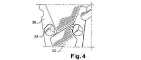
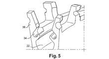
図3、図4および図5に示されるとおり、変形可能領域34が、翼間プラットフォーム(図示せず)の取付フランジ36内に形成された空洞34によって形成され、溝22の側壁(図3から図5)にほぼ沿って延びるフランジ36に固定される。
As shown in FIGS. 3, 4 and 5, a
図3および図4は本発明の最初の2つの実施形態を示し、これらの実施形態では、空洞34は軸方向に向けられ、閉じた底面を有する管形状である。
3 and 4 show the first two embodiments of the present invention, in which the
図5に示される本発明の第3の実施形態では、空洞34は横方向に開いており、溝内に通じている。
In the third embodiment of the invention shown in FIG. 5, the
これらのそれぞれの実施形態では、空洞の直径は、例えば約6から9mmであってもよく、空洞の壁厚は0から3mmであり、深さは約20mmである。これらの値は、約200mmの外径を有するロータディスク10における指針として与えられる。 In each of these embodiments, the cavity diameter may be, for example, about 6 to 9 mm, the cavity wall thickness is 0 to 3 mm, and the depth is about 20 mm. These values are given as a guide for a rotor disk 10 having an outer diameter of about 200 mm.
これらの空洞は、ドリル加工またはフライス加工といった高速の簡単な機械加工方法によって生成されてもよい。 These cavities may be created by high speed simple machining methods such as drilling or milling.
翼間プラットフォームの取付フランジ36に空洞34を設けることにより、空洞は翼の破損時に塑性変形可能になる。翼に作用する引抜力は、空洞34の方向に向けられる。したがって背面フックに加わる応力は減少し、フックの破壊を防止し、翼を溝内の所定の位置に保持でき、ターボ機械が停止するまで、関連のプラットフォームをディスク10のフランジ36に固定して保持できる。さらに、正常動作では、寿命は翼根元部20の軸方向の機械加工(必要でなくなるため)に起因する磨耗によって制限されなくなる。
By providing the
上述のとおり、本発明はフック24を有する翼12において組み合わせて用いる場合に特に有利であるが、本発明はこのタイプの用途に限定されず、他の全てのタイプのファン翼12において利用可能である。
As described above, the present invention is particularly advantageous when used in combination with blades 12 having
10 ロータディスク
12 翼
14 ブレード
18 取付フランジ
20 翼根元部
22 溝
24 フック
26 凹部
28 環状プレート
30 中間部分/フック結合領域
32 凹部/フック結合領域
34 変形可能領域
36 取付フランジ
38 ノッチ
10 rotor disk 12 blade 14 blade 18 mounting
Claims (6)
ディスクの周辺に、下流側端にフックを有する翼根元部を取り付けおよび保持するためのほぼ軸方向の複数の溝と、
溝の下流側端に位置する空洞によって形成される変形可能な領域と、
を備え、
空洞が、溝の側壁にほぼ沿ってその径方向外側に延びる、翼間プラットフォームの取付フランジ内に形成されている、
ロータディスク。 A rotor disk for a turbomachine fan,
A plurality of substantially axial grooves on the periphery of the disk for attaching and holding a blade root having a hook at the downstream end; and
A deformable region formed by a cavity located at the downstream end of the groove;
With
A cavity is formed in the mounting flange of the inter-wing platform that extends radially outward substantially along the sidewall of the groove ;
Rotor disc.
Applications Claiming Priority (2)
| Application Number | Priority Date | Filing Date | Title |
|---|---|---|---|
| FR0700326 | 2007-01-18 | ||
| FR0700326A FR2911632B1 (en) | 2007-01-18 | 2007-01-18 | ROTOR DISC OF TURBOMACHINE BLOWER |
Publications (3)
| Publication Number | Publication Date |
|---|---|
| JP2008180219A JP2008180219A (en) | 2008-08-07 |
| JP2008180219A5 JP2008180219A5 (en) | 2013-05-09 |
| JP5283388B2 true JP5283388B2 (en) | 2013-09-04 |
Family
ID=38421439
Family Applications (1)
| Application Number | Title | Priority Date | Filing Date |
|---|---|---|---|
| JP2008007636A Active JP5283388B2 (en) | 2007-01-18 | 2008-01-17 | Rotor disc for turbomachine fan |
Country Status (6)
| Country | Link |
|---|---|
| US (1) | US8246309B2 (en) |
| EP (1) | EP1950381B1 (en) |
| JP (1) | JP5283388B2 (en) |
| CA (1) | CA2619299C (en) |
| FR (1) | FR2911632B1 (en) |
| RU (1) | RU2454572C2 (en) |
Families Citing this family (15)
| Publication number | Priority date | Publication date | Assignee | Title |
|---|---|---|---|---|
| TWM334886U (en) * | 2007-12-12 | 2008-06-21 | Taiwei Fan Technology Co Ltd | Combination type miniature axial-flow fan |
| DE102009007468A1 (en) * | 2009-02-04 | 2010-08-19 | Mtu Aero Engines Gmbh | Integrally bladed rotor disk for a turbine |
| US8485784B2 (en) * | 2009-07-14 | 2013-07-16 | General Electric Company | Turbine bucket lockwire rotation prevention |
| EP2299056A1 (en) * | 2009-09-02 | 2011-03-23 | Siemens Aktiengesellschaft | Cooling of a gas turbine component shaped as a rotor disc or as a blade |
| FR2955904B1 (en) * | 2010-02-04 | 2012-07-20 | Snecma | TURBOMACHINE BLOWER |
| FR2968363B1 (en) * | 2010-12-03 | 2014-12-05 | Snecma | TURBOMACHINE ROTOR WITH ANTI-WEAR BOND BETWEEN A DISC AND A RING |
| EP2546465A1 (en) | 2011-07-14 | 2013-01-16 | Siemens Aktiengesellschaft | Blade root, corresponding blade, rotor disc, and turbomachine assembly |
| JP2013249756A (en) * | 2012-05-31 | 2013-12-12 | Hitachi Ltd | Compressor |
| EP2971568B1 (en) * | 2013-03-15 | 2021-11-03 | Raytheon Technologies Corporation | Flap seal for a fan of a gas turbine engine |
| JP6266775B2 (en) | 2013-07-26 | 2018-01-24 | エムアールエイ・システムズ・エルエルシー | Aircraft engine pylon |
| FR3014151B1 (en) * | 2013-11-29 | 2015-12-04 | Snecma | BLOWER, ESPECIALLY FOR A TURBOMACHINE |
| FR3064667B1 (en) * | 2017-03-31 | 2020-05-15 | Safran Aircraft Engines | DEVICE FOR COOLING A TURBOMACHINE ROTOR |
| CN107100894A (en) * | 2017-07-05 | 2017-08-29 | 陕西金翼通风科技有限公司 | A kind of installation method of ventilation blower blade, impeller and impeller |
| US10830048B2 (en) | 2019-02-01 | 2020-11-10 | Raytheon Technologies Corporation | Gas turbine rotor disk having scallop shield feature |
| EP3862571A1 (en) * | 2020-02-06 | 2021-08-11 | ABB Schweiz AG | Fan, synchronous machine and method for producing a fan |
Family Cites Families (19)
| Publication number | Priority date | Publication date | Assignee | Title |
|---|---|---|---|---|
| US2965355A (en) * | 1956-01-17 | 1960-12-20 | United Aircraft Corp | Turbine disc burst inhibitor |
| SU387128A1 (en) * | 1971-05-24 | 1973-06-21 | WORKING WHEEL TURBO MOBILE | |
| US4344740A (en) * | 1979-09-28 | 1982-08-17 | United Technologies Corporation | Rotor assembly |
| US4453890A (en) * | 1981-06-18 | 1984-06-12 | General Electric Company | Blading system for a gas turbine engine |
| FR2519072B1 (en) * | 1981-12-29 | 1986-05-30 | Snecma | DEVICE FOR AXIAL AND RADIAL RETENTION OF A TURBO JET ROTOR BLADE |
| FR2695433B1 (en) * | 1992-09-09 | 1994-10-21 | Snecma | Annular seal placed at an axial end of a rotor and covering blade pinouts. |
| US5281098A (en) * | 1992-10-28 | 1994-01-25 | General Electric Company | Single ring blade retaining assembly |
| US5443365A (en) * | 1993-12-02 | 1995-08-22 | General Electric Company | Fan blade for blade-out protection |
| KR20000022064A (en) * | 1996-06-21 | 2000-04-25 | 칼 하인쯔 호르닝어 | Rotor for turbomachine with blades insertable into grooves and blades for rotor |
| RU2173390C2 (en) * | 1996-06-21 | 2001-09-10 | Сименс Акциенгезелльшафт | Turbo-machine rotor accommodating blades in its slots and rotor blades |
| US6183202B1 (en) * | 1999-04-30 | 2001-02-06 | General Electric Company | Stress relieved blade support |
| GB9925261D0 (en) * | 1999-10-27 | 1999-12-29 | Rolls Royce Plc | Locking devices |
| FR2803623B1 (en) * | 2000-01-06 | 2002-03-01 | Snecma Moteurs | ARRANGEMENT FOR AXIAL RETENTION OF BLADES IN A DISC |
| US6481971B1 (en) * | 2000-11-27 | 2002-11-19 | General Electric Company | Blade spacer |
| US6634863B1 (en) * | 2000-11-27 | 2003-10-21 | General Electric Company | Circular arc multi-bore fan disk assembly |
| GB2380770B (en) * | 2001-10-13 | 2005-09-07 | Rolls Royce Plc | Indentor arrangement |
| GB2409240B (en) * | 2003-12-18 | 2007-04-11 | Rolls Royce Plc | A gas turbine rotor |
| JP2005273646A (en) * | 2004-02-25 | 2005-10-06 | Mitsubishi Heavy Ind Ltd | Moving blade element and rotary machine having the moving blade element |
| EP1703079A1 (en) * | 2005-08-26 | 2006-09-20 | Siemens Aktiengesellschaft | Rotational solid for fixing of blades of a turbo-machine |
-
2007
- 2007-01-18 FR FR0700326A patent/FR2911632B1/en active Active
- 2007-12-27 EP EP07291632.3A patent/EP1950381B1/en active Active
-
2008
- 2008-01-16 CA CA2619299A patent/CA2619299C/en active Active
- 2008-01-17 JP JP2008007636A patent/JP5283388B2/en active Active
- 2008-01-17 RU RU2008101906/06A patent/RU2454572C2/en active
- 2008-01-18 US US12/016,517 patent/US8246309B2/en active Active
Also Published As
| Publication number | Publication date |
|---|---|
| FR2911632A1 (en) | 2008-07-25 |
| US20080298972A1 (en) | 2008-12-04 |
| FR2911632B1 (en) | 2009-08-21 |
| RU2454572C2 (en) | 2012-06-27 |
| EP1950381B1 (en) | 2016-03-02 |
| JP2008180219A (en) | 2008-08-07 |
| RU2008101906A (en) | 2009-07-27 |
| CA2619299A1 (en) | 2008-07-18 |
| EP1950381A1 (en) | 2008-07-30 |
| CA2619299C (en) | 2015-06-09 |
| US8246309B2 (en) | 2012-08-21 |
Similar Documents
| Publication | Publication Date | Title |
|---|---|---|
| JP5283388B2 (en) | Rotor disc for turbomachine fan | |
| JP5613764B2 (en) | Impeller for turbomachinery | |
| JP6105234B2 (en) | Turbine rotor blade assembly and method of assembling the same | |
| JP4237176B2 (en) | Gas turbine engine and turbine engine rotor | |
| EP2586980B1 (en) | Device for damping of vibrational energy in turbine blades and corresponding rotor | |
| EP1602801B1 (en) | Rotor blade with a stick damper | |
| US5820343A (en) | Airfoil vibration damping device | |
| JP5179029B2 (en) | Fluid machine with radial compressor impeller and insert housing part for incorporation in a fluid machine | |
| JP2008180219A5 (en) | ||
| JP4808997B2 (en) | Fluid machinery | |
| JP2004204839A (en) | Shroud segment and assembly with surface recessed seal bridging adjacent member | |
| JP5478613B2 (en) | Turbomachine fan rotor | |
| JP2014005834A (en) | Turbomachine fan | |
| JP2003035165A (en) | Centripetal air-bleed system | |
| JP2007064074A (en) | Axial flow turbine | |
| US9441494B2 (en) | Turbomachine rotor with a means for axial retention of the blades | |
| JP2015531444A (en) | Friction resistant fan case | |
| KR20110102908A (en) | Turbine wheel with an axial retention system for vanes | |
| WO2013128973A1 (en) | Structure for retaining turbine rotor blade, and rotary machine with same | |
| US7118346B2 (en) | Compressor blade | |
| JP2012052523A (en) | Turbine blade assembly | |
| CN102869851B (en) | Turbojet engine fan, turbojet engine and wear-resistant part | |
| JP6869174B2 (en) | Fan rotors, assemblies, and airplane turbojet or turboprop engines | |
| JP5149831B2 (en) | Turbine blade fixed structure and turbine | |
| EP3926145B1 (en) | Turbine stator blade |
Legal Events
| Date | Code | Title | Description |
|---|---|---|---|
| A621 | Written request for application examination |
Free format text: JAPANESE INTERMEDIATE CODE: A621 Effective date: 20101228 |
|
| A131 | Notification of reasons for refusal |
Free format text: JAPANESE INTERMEDIATE CODE: A131 Effective date: 20111206 |
|
| A601 | Written request for extension of time |
Free format text: JAPANESE INTERMEDIATE CODE: A601 Effective date: 20120302 |
|
| A602 | Written permission of extension of time |
Free format text: JAPANESE INTERMEDIATE CODE: A602 Effective date: 20120307 |
|
| A521 | Request for written amendment filed |
Free format text: JAPANESE INTERMEDIATE CODE: A523 Effective date: 20120605 |
|
| A131 | Notification of reasons for refusal |
Free format text: JAPANESE INTERMEDIATE CODE: A131 Effective date: 20121009 |
|
| RD02 | Notification of acceptance of power of attorney |
Free format text: JAPANESE INTERMEDIATE CODE: A7422 Effective date: 20121109 |
|
| RD04 | Notification of resignation of power of attorney |
Free format text: JAPANESE INTERMEDIATE CODE: A7424 Effective date: 20121211 |
|
| A601 | Written request for extension of time |
Free format text: JAPANESE INTERMEDIATE CODE: A601 Effective date: 20121212 |
|
| A602 | Written permission of extension of time |
Free format text: JAPANESE INTERMEDIATE CODE: A602 Effective date: 20121217 |
|
| A524 | Written submission of copy of amendment under article 19 pct |
Free format text: JAPANESE INTERMEDIATE CODE: A524 Effective date: 20130325 |
|
| TRDD | Decision of grant or rejection written | ||
| A01 | Written decision to grant a patent or to grant a registration (utility model) |
Free format text: JAPANESE INTERMEDIATE CODE: A01 Effective date: 20130514 |
|
| A61 | First payment of annual fees (during grant procedure) |
Free format text: JAPANESE INTERMEDIATE CODE: A61 Effective date: 20130528 |
|
| R150 | Certificate of patent or registration of utility model |
Ref document number: 5283388 Country of ref document: JP Free format text: JAPANESE INTERMEDIATE CODE: R150 |
|
| R250 | Receipt of annual fees |
Free format text: JAPANESE INTERMEDIATE CODE: R250 |
|
| R250 | Receipt of annual fees |
Free format text: JAPANESE INTERMEDIATE CODE: R250 |
|
| R250 | Receipt of annual fees |
Free format text: JAPANESE INTERMEDIATE CODE: R250 |
|
| R250 | Receipt of annual fees |
Free format text: JAPANESE INTERMEDIATE CODE: R250 |
|
| R250 | Receipt of annual fees |
Free format text: JAPANESE INTERMEDIATE CODE: R250 |
|
| R250 | Receipt of annual fees |
Free format text: JAPANESE INTERMEDIATE CODE: R250 |
|
| R250 | Receipt of annual fees |
Free format text: JAPANESE INTERMEDIATE CODE: R250 |
|
| R250 | Receipt of annual fees |
Free format text: JAPANESE INTERMEDIATE CODE: R250 |